EP2582211A1 - DALI Verteilerbox - Google Patents
DALI Verteilerbox Download PDFInfo
- Publication number
- EP2582211A1 EP2582211A1 EP12188111.4A EP12188111A EP2582211A1 EP 2582211 A1 EP2582211 A1 EP 2582211A1 EP 12188111 A EP12188111 A EP 12188111A EP 2582211 A1 EP2582211 A1 EP 2582211A1
- Authority
- EP
- European Patent Office
- Prior art keywords
- dali
- connection
- group
- control unit
- bus
- Prior art date
- Legal status (The legal status is an assumption and is not a legal conclusion. Google has not performed a legal analysis and makes no representation as to the accuracy of the status listed.)
- Granted
Links
Images
Classifications
-
- H—ELECTRICITY
- H05—ELECTRIC TECHNIQUES NOT OTHERWISE PROVIDED FOR
- H05B—ELECTRIC HEATING; ELECTRIC LIGHT SOURCES NOT OTHERWISE PROVIDED FOR; CIRCUIT ARRANGEMENTS FOR ELECTRIC LIGHT SOURCES, IN GENERAL
- H05B47/00—Circuit arrangements for operating light sources in general, i.e. where the type of light source is not relevant
- H05B47/10—Controlling the light source
-
- H—ELECTRICITY
- H05—ELECTRIC TECHNIQUES NOT OTHERWISE PROVIDED FOR
- H05B—ELECTRIC HEATING; ELECTRIC LIGHT SOURCES NOT OTHERWISE PROVIDED FOR; CIRCUIT ARRANGEMENTS FOR ELECTRIC LIGHT SOURCES, IN GENERAL
- H05B47/00—Circuit arrangements for operating light sources in general, i.e. where the type of light source is not relevant
- H05B47/10—Controlling the light source
- H05B47/175—Controlling the light source by remote control
- H05B47/18—Controlling the light source by remote control via data-bus transmission
- H05B47/183—Controlling the light source by remote control via data-bus transmission using digital addressable lighting interface [DALI] communication protocols
-
- H—ELECTRICITY
- H05—ELECTRIC TECHNIQUES NOT OTHERWISE PROVIDED FOR
- H05B—ELECTRIC HEATING; ELECTRIC LIGHT SOURCES NOT OTHERWISE PROVIDED FOR; CIRCUIT ARRANGEMENTS FOR ELECTRIC LIGHT SOURCES, IN GENERAL
- H05B47/00—Circuit arrangements for operating light sources in general, i.e. where the type of light source is not relevant
- H05B47/10—Controlling the light source
- H05B47/175—Controlling the light source by remote control
- H05B47/198—Grouping of control procedures or address assignation to light sources
Definitions
- the present invention relates to a distribution box which has at least one DALI control unit or a DALI bus connection and a plurality of luminaire connections which are connected in the distribution box to the DALI control unit or the DALI bus connection, respectively. wherein each terminal for the lights is assigned a selector switch for selecting the group affiliation of the respective terminal.
- the present invention relates here to a distribution box or a distribution box, to which or several DALI-compatible lights can be connected.
- a distribution box or a distribution box to which or several DALI-compatible lights can be connected.
- lights which are arranged in several, preferably adjacent, rooms are connected to a distribution box, in which case a group assignment corresponding to the rooms takes place.
- the connections for the luminaires are in this case designed in the distributor box in such a way that the luminaires are coupled to corresponding power supply lines on the one hand and are also connected to a DALI control unit arranged in the distributor box or a connection for a DALI bus.
- the distributor box is connected to a power supply network and, in the event that the distributor box has a connection for a DALI bus, also connected to an external DALI bus, wherein the coupling or connection of the lamps or the connections for the lamps to the Power supply network and the DALI control unit or the external DALI bus in the distribution box. From the point of view of the DALI control unit or of the external DALI bus, all luminaires connected to the distributor box are connected in parallel in order to allow other control elements connected to the distributor box to switch or operate the luminaires together or in groups.
- the distribution box for each of the connections for the lights has a manual selector switch, with which the respective terminal can be assigned to a specific group. With this selector so a group affiliation of the respective port is manually determined by a user.
- the object of the present invention is to further develop a distributor box such that the connections for the lights of the distributor box are assigned a DALI group address in accordance with their manually selected group membership.
- a distributor box which has at least one DALI control unit or a connection for a DALI bus and a plurality of connections for lamps which are connected in the distribution box to the DALI control unit or to the connection for the DALI bus.
- each terminal for the lights is assigned a selector switch for selecting the group affiliation of the respective terminal.
- each connection for the luminaires has a disconnecting device which can disconnect the connection to the DALI control unit or the connection for the DALI bus, wherein the disconnecting devices are designed to connect in dependence on the selection of the group affiliation to separate.
- the separating devices can be designed to independently and automatically separate the connection depending on the selection of the group membership, wherein the connection is separated by the DALI control unit or via the DALI bus depending on the selection of the group membership during the allocation of the group addresses becomes.
- the connection is disconnected if the selection of the group membership does not correspond to the group selected by the DALI control unit or via the DALI bus.
- This solution according to the invention thus makes it possible for the luminaires which are connected to the corresponding connections to be separated individually or selectively from the DALI control unit or from the DALI bus, as a result of which an unambiguous assignment of each luminaire or each connection is possible for the lights to a particular group.
- the disconnecting devices are selectively controlled by the group memberships which were previously set manually at the selector switches so that the associated lights can or can not receive the DALI commands via which the group address is assigned.
- the distributor box has a connection for a power supply, wherein the connections for the lamps in the distributor box are connected to the connection for the power supply.
- the disconnecting devices are switches which can be designed as semiconductor components, in particular transistors.
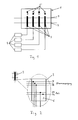
- FIG. 1 shows a distributor box 1 according to the invention, which has a connection 2 for a DALI bus, a connection 7 for a power supply and a plurality of connections 3 for lamps 4.
- a connection 2 for a DALI bus a connection for a DALI bus
- a connection 7 for a power supply a connection for a power supply
- a plurality of connections 3 for lamps 4 a connection for the lights 4 .
- FIG. 2 shows enlarged. How out FIG. 2
- each of the connections 3 for the luminaires 4 is connected both to the connection 7 for the power supply and thus to the power supply as well as to the connection 2 for the DALI bus and thus to the DALI bus in the distribution box 1.
- the distributor box 1 has, for each connection 3 for the luminaires 4, a selector switch 5 with which a manual selection of the group affiliation of the corresponding terminal 3 can be made.
- the selector switch 5 are in this case designed such that a selection between two different positions and accordingly the connections 3 for the lights 4 either a first group or a second group can be assigned.
- each terminal 3 for the lamps 4 has a separator 6 designed as a switch, which can disconnect the connection to the terminal 2 for the DALI bus, whereby each individual terminal 3 for the lamps 4 is selectively opened or disconnected can be.
- the separator 6 may be arranged in the return line to the DALI bus.
- the isolators 6 will be closed after the addresses or DALI group addresses have been assigned, to allow all luminaires 4 to receive DALI commands during normal operation.
- the separation devices 6 it is now possible that the infected lights 4 can be identified without changing their light output, making it possible that the lights 4 is assigned a corresponding DALI group address.
- the separation devices 6 can be selectively opened or closed, for example, by software control, this taking place in accordance with the manual selection of the group membership.
- the disconnecting device 6 is opened or closed in accordance with the manual selection of the group affiliation of the associated selector switch 5 at each connection 3 for the luminaires 4.
- the DALI group addresses are assigned for a first group, so only the separation devices 6 are closed, in which also the selection switches 5 are set to the first group.
- the selector switches 5 indicate the first group in the upper position and the second group in the lower position, these would be the disconnectors 6 of the first and third terminals 3 seen from the left for the lamps 4.
- the separator 6 In the case of the second and fourth terminals 3, in which the selector switch 5 are in the lower position for the second group, the separator 6 would be open, whereby the respective terminal 3 for the lights 4 and thus the correspondingly connected light 4 would be separated from the DALI bus. Then can then be sent via the DALI bus corresponding commands through which a DALI group address assignment takes place, with only the lights 4, which are connected to the first and third connection 3 for the lights 4, the commands can receive accordingly.
- the separation devices 6 of the first and third connection 3 for the lights 4 would be opened and the separation devices 6 of the second and fourth connection 3 for the Luminaires 4 closed according to the position of the selector switch 5, which in turn can be done a corresponding DALI group address assignment.
- the distributor box has a DALI control unit, with which the connections for the lamps can then be connected correspondingly instead of the connection for the DALI bus.
- the distributor box can be connected to any higher-level bus system, for example also to a DALI bus.
- switch disconnectors 6 may also be, for example, simple and inexpensive semiconductor devices, such as transistors, whereby a software-controlled control of the separation devices 6 is made possible in a simple manner.
Landscapes
- Circuit Arrangement For Electric Light Sources In General (AREA)
Abstract
Description
- Die vorliegende Erfindung betrifft eine Verteilerbox, die zumindest eine DALI-Steuereinheit oder einen Anschluss für einen DALI-Bus und mehrere Anschlüsse für Leuchten, die in der Verteilerbox mit der DALI-Steuereinheit bzw. dem Anschluss für den DALI-Bus verbunden sind, aufweist, wobei jedem Anschluss für die Leuchten ein Wahlschalter zur Auswahl der Gruppenzugehörigkeit des jeweiligen Anschlusses zugeordnet ist.
- Bei größeren Beleuchtungssystemen ist häufig vorgesehen, dass verschiedenen Leuchten eines Beleuchtungssystems geeignete Gruppenadressen entsprechend beispielsweise dem DALI-Standard zugewiesen werden. Die vorliegende Erfindung bezieht sich hierbei auf einen Verteilerkasten bzw. eine Verteilerbox, an den bzw. die mehrere DALI-kompatible Leuchten angeschlossen werden können. Bei derartigen Verteilerboxen ist es bei größeren Beleuchtungssystemen dabei häufig vorgesehen, u.a. in England, dass Leuchten, die in mehreren, vorzugsweise benachbarten, Räumen angeordnet sind, an einer Verteilerbox angeschlossen werden, wobei dann eine Gruppenzuordnung entsprechenden den Räumen erfolgt.
- Die Anschlüsse für die Leuchten sind in der Verteilerbox hierbei derart ausgestaltet, dass die Leuchten zum einen mit entsprechenden Stromversorgungsleitungen gekoppelt sind, und zum anderen auch mit einer in der Verteilerbox angeordneten DALI-Steuereinheit oder einem Anschluss für einen DALI-Bus verbunden werden. Die Verteilerbox ist hierzu an ein Stromversorgungsnetz und für den Fall, dass die Verteilerbox einen Anschluss für einen DALI-Bus aufweist, auch an einen externen DALI-Bus angeschlossen, wobei die Kopplung bzw. Verbindung der Leuchten bzw. der Anschlüsse für die Leuchten mit dem Stromversorgungsnetz und der DALI-Steuereinheit bzw. dem externen DALI-Bus in der Verteilerbox erfolgt. Aus Sicht der DALI-Steuereinheit bzw. des externen DALI-Busses sind hierbei alle an die Verteilerbox angesteckten Leuchten parallel geschaltet, um anderen an die Verteilerbox angeschlossenen Bedienelementen zu ermöglichen, die Leuchten gemeinsam oder in Gruppen zu schalten bzw. zu bedienen.
- Bisher ist es zumeist üblich, dass die Verteilerbox für jeden der Anschlüsse für die Leuchten einen manuellen Wahlschalter aufweist, mit dem der jeweilige Anschluss einer bestimmten Gruppe zugeordnet werden kann. Mit diesem Wahlschalter wird also eine Gruppenzugehörigkeit des jeweiligen Anschlusses manuell durch einen Benutzer festgelegt.
- Diese manuelle Festlegung der Gruppenzugehörigkeit eignet sich allerdings nicht für die Verwendung der Leuchten und der Verteilerbox im Zusammenhang mit dem DALI-Standard. Für diesen ist es erforderlich, dass den Leuchten auch die entsprechenden DALI-Gruppenadressen zugewiesen werden, wobei diese Zuweisung der der manuell gewählten Gruppenzugehörigkeit der Leuchten bzw. der Anschlüsse für die Leuchten entsprechen sollte.
- Der vorliegenden Erfindung liegt dementsprechend die Aufgabe zugrunde, eine Verteilerbox derart weiterzuentwickeln, dass die Anschlüsse für die Leuchten der Verteilerbox entsprechend ihrer manuell gewählten Gruppenzugehörigkeit eine DALI-Gruppenadresse zugewiesen bekommen.
- Die Aufgabe wird durch eine Verteilerbox gemäß Anspruch 1 gelöst. Vorteilhafte Weiterbildungen der Erfindung sind Gegenstand der abhängigen Ansprüche.
- Erfindungsgemäß wird nun eine Verteilerbox vorgeschlagen, die zumindest eine DALI-Steuereinheit oder einen Anschluss für einen DALI-Bus und mehrere Anschlüsse für Leuchten, die in der Verteilerbox mit der DALI-Steuereinheit bzw. dem Anschluss für den DALI-Bus verbunden sind, aufweist, wobei jedem Anschluss für die Leuchten ein Wahlschalter zur Auswahl der Gruppenzugehörigkeit des jeweiligen Anschlusses zugeordnet ist. Hierbei ist dann vorgesehen, dass jeder Anschluss für die Leuchten eine Trennvorrichtung aufweist, die die Verbindung zu der DALI-Steuereinheit bzw. dem Anschluss für den DALI-Bus trennen kann, wobei die Trennvorrichtungen dazu ausgebildet sind, die Verbindung in Abhängigkeit der Auswahl der Gruppenzugehörigkeit zu trennen.
- Vorteilhafterweise ermöglichen hierbei die Wahlschalter eine manuelle Auswahl der Gruppenzugehörigkeit. Des Weiteren können die Trennvorrichtungen dazu ausgebildet sein, die Verbindung in Abhängigkeit der Auswahl der Gruppenzugehörigkeit selbstständig und automatisch zu trennen, wobei die Verbindung in Abhängigkeit der Auswahl der Gruppenzugehörigkeit während der Vergabe der Gruppenadressen durch die DALI-Steuereinheit bzw. über den DALI-Bus getrennt wird. Insbesondere kann hierbei vorgesehen sein, dass die Verbindung getrennt wird, wenn die Auswahl der Gruppenzugehörigkeit nicht der Gruppe entspricht, die durch die DALI-Steuereinheit bzw. über den DALI-Bus ausgewählt ist.
- Durch diese erfindungsgemäße Lösung ist es somit möglich, dass die Leuchten, die an den entsprechenden Anschlüssen angeschlossen sind, einzeln bzw. selektiv von der DALI-Steuereinheit bzw. vom DALI-Bus abgetrennt werden können, wodurch eine eindeutige Zuordnung jeder Leuchte bzw. jedes Anschlusses für die Leuchten zu einer bestimmten Gruppe möglich wird.
- Während einer Adressvergabe ist es damit möglich, dass durch die an den Wahlschaltern zuvor manuell eingestellten Gruppenzugehörigkeiten die Trennvorrichtungen selektiv so angesteuert werden, dass die zugehörigen Leuchten die DALI-Befehle, über welche die Gruppenadresse zugewiesen wird, empfangen können bzw. nicht empfangen können. Hierbei ist insbesondere vorgesehen, dass die Trennvorrichtungen die Verbindung zur DALI-Steuereinheit bzw. zum DALI-Bus für alle Anschlüsse trennen, die entsprechend der Auswahl der Gruppenzugehörigkeit nicht zu der Gruppe gehören, die zu diesem Zeitpunkt DALI-Befehle empfangen sollen, mit denen eine bestimmte DALI-Gruppenadresse zugewiesen wird.
- Nach der Adressierung bzw. der Vergabe der DALI-Gruppenadressen ist dann vorteilhafterweise vorgesehen, dass die Trennvorrichtungen die Verbindung geschlossen halten, da es im weiteren Betrieb notwendig ist, dass alle Leuchten die DALI-Befehle empfangen können.
- Des Weiteren ist vorteilhafterweise vorgesehen, dass die Verteilerbox einen Anschluss für eine Stromversorgung aufweist, wobei die Anschlüsse für die Leuchten in der Verteilerbox mit dem Anschluss für die Stromversorgung verbunden sind. Vorzugsweise ist des Weiteren vorgesehen, dass es sich bei den Trennvorrichtungen um Schalter handelt, die als Halbleiterbauelemente, insbesondere Transistoren, ausgebildet sein können.
- Nachfolgend soll die Erfindung anhand von Ausführungsbeispielen und den beiliegenden Zeichnungen näher erläutert werden. Es zeigen:
- Figur 1
- schematische Darstellung einer erfindungsgemäßen Verteilerbox;
- Figur 2
- vergrößerte Darstellung eines Anschlusses für Leuchten der erfindungsgemäßen Verteilerbox.
-
Figur 1 zeigt eine erfindungsgemäße Verteilerbox 1, die einen Anschluss 2 für einen DALI-Bus, einen Anschluss 7 für eine Stromversorgung und mehrere Anschlüsse 3 für Leuchten 4 aufweist. InFigur 2 ist dann einer der Anschlüsse 3 für die Leuchten 4 vergrößert dargestellt. Wie ausFigur 2 hervorgeht, ist jeder der Anschlüsse 3 für die Leuchten 4 sowohl mit dem Anschluss 7 für die Stromversorgung und somit mit der Stromversorgung als auch mit dem Anschluss 2 für den DALI-Bus und somit mit dem DALI-Bus in der Verteilerbox 1 verbunden. - Die Verteilerbox 1 weist des Weiteren noch für jeden Anschluss 3 für die Leuchten 4 einen Wahlschalter 5 auf, mit dem eine manuelle Auswahl der Gruppenzugehörigkeit des entsprechenden Anschlusses 3 getroffen werden kann. Bei dem in
Figur 1 gezeigten Ausführungsbeispiel sind die Wahlschalter 5 hierbei derart ausgestaltet, dass eine Auswahl zwischen zwei verschiedenen Positionen besteht und dementsprechend die Anschlüsse 3 für die Leuchten 4 entweder einer ersten Gruppe oder einer zweiten Gruppe zugeordnet werden können. - Zusätzlich ist noch vorgesehen, dass jeder Anschluss 3 für die Leuchten 4 eine als Schalter ausgebildete Trennvorrichtung 6 aufweist, die die Verbindung zu dem Anschluss 2 für den DALI-Bus trennen kann, wodurch jeder einzelne Anschluss 3 für die Leuchten 4 selektiv geöffnet bzw. getrennt werden kann. Wie aus
Figur 2 hervorgeht, reicht es aus, wenn die Trennvorrichtung 6 die Verbindung zu einer der beiden DALI-Leitungen trennt, wobei beispielsweise die Trennvorrichtung 6 in der Rückleitung zum DALI-Bus angeordnet sein kann. Hierbei ist jedoch vorgesehen, dass die Trennvorrichtungen 6 nach der Vergabe der Adressen bzw. der DALI-Gruppenadressen geschlossen sind, um zu ermöglichen, dass alle Leuchten 4 während des normalen Betriebes DALI-Befehle empfangen können. - Durch die Trennvorrichtungen 6 ist es nunmehr möglich, dass die daran angesteckten Leuchten 4 ohne Veränderung ihres Lichtausgangs identifiziert werden können, wodurch es möglich wird, dass den Leuchten 4 eine entsprechende DALI-Gruppenadresse zugewiesen wird. Hierzu ist vorgesehen, dass die Trennvorrichtungen 6 beispielsweise softwaregesteuert selektiv geöffnet bzw. geschlossen werden können, wobei dies entsprechend der manuellen Auswahl der Gruppenzugehörigkeit erfolgt.
- Im Einzelnen wird hierbei bei jedem Anschluss 3 für die Leuchten 4 die Trennvorrichtung 6 entsprechend der manuellen Auswahl der Gruppenzugehörigkeit des zugehörigen Wahlschalters 5 geöffnet bzw. geschlossen. Soll beispielweise bei dem in
Figur 1 gezeigten Ausführungsbeispiel die DALI-Gruppenadresse für eine erste Gruppe vergeben werden, so sind lediglich die Trennvorrichtungen 6 geschlossen, bei denen auch die Wahlschalter 5 auf die erste Gruppe eingestellt sind. Ausgehend davon, dass inFigur 1 die Wahlschalter 5 in der oberen Position die erste Gruppe anzeigen und in der unteren Position die zweite Gruppe, wären dies die Trennvorrichtungen 6 des von links gesehenen ersten und dritten Anschlusses 3 für die Leuchten 4. Bei dem zweiten und vierten Anschluss 3 hingegen, bei denen die Wahlschalter 5 in der unteren Position für die zweite Gruppe sind, würde die Trennvorrichtung 6 geöffnet sein, wodurch der jeweilige Anschluss 3 für die Leuchten 4 und somit die entsprechend angeschlossene Leuchte 4 vom DALI-Bus getrennt wäre. Daraufhin können dann über den DALI-Bus entsprechende Befehle versendet werden, durch die eine DALI-Gruppenadressenzuweisung erfolgt, wobei lediglich die Leuchten 4, die am ersten und dritten Anschluss 3 für die Leuchten 4 angeschlossen sind, die Befehle entsprechend empfangen können. - In einem weiteren Schritt, zur Gruppenadressierung der zweiten Gruppe, würden dann die Trennvorrichtungen 6 des ersten und dritten Anschlusses 3 für die Leuchten 4 geöffnet und die Trennvorrichtungen 6 des zweiten und vierten Anschlusses 3 für die Leuchten 4 entsprechend der Stellung der Wahlschalter 5 geschlossen, woraufhin wiederum eine entsprechende DALI-Gruppenadressenzuweisung erfolgen kann.
- Des Weiteren kann auch vorgesehen sein, dass die Verteilerbox eine DALI-Steuereinheit aufweist, mit der dann anstelle des Anschlusses für den DALI-Bus die Anschlüsse für die Leuchten entsprechend verbunden sein können. Hierdurch ergibt sich für die Verteilerbox ein weitgehend autarkes lokales System, bei dem durch die integrierte DALI-Steuereinheit kein externer DALI-Bus mehr vorhanden sein muss. Zusätzlich besteht hierbei aber trotzdem auch die Möglichkeit, dass die Verteilerbox an ein beliebiges übergeordnetes Bussystem, beispielsweise auch an einen DALI-Bus, angeschlossen sein kann.
- Durch die erfindungsgemäße Ausgestaltung ist es somit möglich, dass während der Vergabe der DALI-Gruppenadressen jeweils immer nur die Leuchten in Verbindung mit der DALI-Steuereinheit bzw. dem DALI-Bus stehen, die einer bestimmten Gruppe angehören, wobei diese Gruppenzugehörigkeit vorher manuell an den entsprechenden Wahlschaltern 5 ausgewählt wurde. Dementsprechend wird die manuell getroffene Auswahl der Gruppenzugehörigkeit automatisch in eine DALI-Gruppenadresse umgesetzt, ohne dass hier ein weiterer Eingriff bzw. eine weitere Eingabe durch einen Benutzer notwendig wäre. Die Zuordnung der DALI-Gruppenadressen entsprechend der Stellung der Wahlschalter 5 erfolgt somit selbstständig und voll automatisch.
- Bei den als Schalter ausgebildeten Trennvorrichtungen 6 kann es sich zudem beispielsweise um einfache und kostengünstige Halbleiterbauelemente, wie Transistoren handeln, wodurch auch eine softwaregesteuerte Ansteuerung der Trennvorrichtungen 6 auf einfache Weise ermöglicht wird.
Claims (9)
- Verteilerbox (1) aufweisend- zumindest eine DALI-Steuereinheit oder einen Anschluss (2) für einen DALI-Bus und- mehrere Anschlüsse (3) für Leuchten (4), die in der Verteilerbox (1) mit der DALI-Steuereinheit bzw. dem Anschluss (2) für den DALI-Bus verbunden sind,wobei jedem Anschluss (3) für die Leuchten (4) ein Wahlschalter (5) zur Auswahl der Gruppenzugehörigkeit des jeweiligen Anschlusses (3) zugeordnet ist,
dadurch gekennzeichnet,
dass jeder Anschluss (3) für die Leuchten (4) eine Trennvorrichtung (6) aufweist, die die Verbindung zu der DALI-Steuereinheit bzw. dem Anschluss (2) für den DALI-Bus trennen kann, wobei die Trennvorrichtungen (6) dazu ausgebildet sind, die Verbindung in Abhängigkeit der Auswahl der Gruppenzugehörigkeit zu trennen. - Verteilerbox nach Anspruch 1,
dadurch gekennzeichnet,
dass die Wahlschalter (5) eine manuelle Auswahl der Gruppenzugehörigkeit ermöglichen. - Verteilerbox nach einem der Ansprüche 1 oder 2,
dadurch gekennzeichnet,
dass die Trennvorrichtungen (6) dazu ausgebildet sind, die Verbindung in Abhängigkeit der Auswahl der Gruppenzugehörigkeit selbstständig und automatisch zu trennen. - Verteilerbox nach einem der vorherigen Ansprüche,
dadurch gekennzeichnet,
dass die Trennvorrichtungen (6) dazu ausgebildet sind, während der Vergabe der Gruppenadressen durch die DALI-Steuereinheit bzw. über den DALI-Bus, die Verbindung in Abhängigkeit der Auswahl der Gruppenzugehörigkeit zu trennen. - Verteilerbox nach Anspruch 4,
dadurch gekennzeichnet,
dass die Trennvorrichtungen (6) dazu ausgebildet sind, die Verbindung zu trennen, wenn die Auswahl der Gruppenzugehörigkeit nicht der durch die DALI-Steuereinheit bzw. über den DALI-Bus ausgewählten Gruppe entspricht. - Verteilerbox nach einem der Ansprüche 4 oder 5,
dadurch gekennzeichnet,
dass die Trennvorrichtungen (6) dazu ausgebildet sind, nach der Vergabe der Gruppenadressen durch die DALI-Steuereinheit bzw. über den DALI-Bus, die Verbindung geschlossen zu halten. - Verteilerbox nach einem der vorherigen Ansprüche,
dadurch gekennzeichnet,
dass die Verteilerbox (1) einen Anschluss (7) für eine Stromversorgung aufweist, wobei die Anschlüsse (3) für die Leuchten (4) in der Verteilerbox (1) mit dem Anschluss (7) für die Stromversorgung verbunden sind. - Verteilerbox nach einem der vorherigen Ansprüche,
dadurch gekennzeichnet,
dass es sich bei den Trennvorrichtungen um Schalter (6) handelt. - Verteilerbox nach Anspruch 8,
dadurch gekennzeichnet,
dass die Schalter (6) als Halbleiterbauelemente, insbesondere Transistoren, ausgebildet sind.
Applications Claiming Priority (1)
| Application Number | Priority Date | Filing Date | Title |
|---|---|---|---|
| DE102011084494A DE102011084494A1 (de) | 2011-10-14 | 2011-10-14 | Verteilerbox |
Publications (2)
| Publication Number | Publication Date |
|---|---|
| EP2582211A1 true EP2582211A1 (de) | 2013-04-17 |
| EP2582211B1 EP2582211B1 (de) | 2015-01-07 |
Family
ID=47263037
Family Applications (1)
| Application Number | Title | Priority Date | Filing Date |
|---|---|---|---|
| EP12188111.4A Active EP2582211B1 (de) | 2011-10-14 | 2012-10-11 | DALI Verteilerbox |
Country Status (2)
| Country | Link |
|---|---|
| EP (1) | EP2582211B1 (de) |
| DE (1) | DE102011084494A1 (de) |
Citations (4)
| Publication number | Priority date | Publication date | Assignee | Title |
|---|---|---|---|---|
| DE19817073A1 (de) * | 1998-04-17 | 1999-10-28 | Erco Leuchten | Vorrichtung zur Steuerung einer Mehrzahl von Beleuchtungselementen |
| DE10202714A1 (de) * | 2002-01-24 | 2003-07-31 | Luxmate Controls Gmbh Dornbirn | Verfahren zum Zuordnen von Betriebsadressen in einem Steuersystem für eine Vielzahl von Aktoren |
| DE10204809A1 (de) * | 2002-02-06 | 2003-08-14 | Insta Elektro Gmbh | Gebäudeinstallationssystem |
| DE202006006633U1 (de) * | 2006-04-21 | 2007-09-06 | Erco Leuchten Gmbh | Leuchtensteuerungssystem |
-
2011
- 2011-10-14 DE DE102011084494A patent/DE102011084494A1/de not_active Withdrawn
-
2012
- 2012-10-11 EP EP12188111.4A patent/EP2582211B1/de active Active
Patent Citations (4)
| Publication number | Priority date | Publication date | Assignee | Title |
|---|---|---|---|---|
| DE19817073A1 (de) * | 1998-04-17 | 1999-10-28 | Erco Leuchten | Vorrichtung zur Steuerung einer Mehrzahl von Beleuchtungselementen |
| DE10202714A1 (de) * | 2002-01-24 | 2003-07-31 | Luxmate Controls Gmbh Dornbirn | Verfahren zum Zuordnen von Betriebsadressen in einem Steuersystem für eine Vielzahl von Aktoren |
| DE10204809A1 (de) * | 2002-02-06 | 2003-08-14 | Insta Elektro Gmbh | Gebäudeinstallationssystem |
| DE202006006633U1 (de) * | 2006-04-21 | 2007-09-06 | Erco Leuchten Gmbh | Leuchtensteuerungssystem |
Also Published As
| Publication number | Publication date |
|---|---|
| EP2582211B1 (de) | 2015-01-07 |
| DE102011084494A1 (de) | 2013-04-18 |
Similar Documents
| Publication | Publication Date | Title |
|---|---|---|
| EP0790541B1 (de) | Anschlusseinrichtung für ein elektrisches Installationssystem | |
| EP2287689B1 (de) | Vorrichtung und Verfahren zur Adressierung einer Slave-Einheit | |
| EP1174781B1 (de) | Einrichtung zur Signalübertragung | |
| EP0210123B1 (de) | Schaltungsanordnung zur netzunabhängigen Spannungsversorgung einer an ein Busnetzwerk angeschlossenen Verteileinrichtung für Datenstationen | |
| DE102010029300A1 (de) | Netzwerkschnittstelle und Verfahren zur Datenübertragung | |
| WO2019228911A1 (de) | Automatisierungssystem, betriebsverfahren für automatisierungssystem und computerprogrammprodukt | |
| EP3251469B1 (de) | Verfahren zum betreiben von geräten in einem beleuchtungssystem | |
| DE102016213724A1 (de) | Reihenmodul, Funktionsmodulanordnung und modular ausgebildete Steuerungsanordnung | |
| DE102015011317A1 (de) | Modularer HF-Matrix-Switch | |
| EP2009522B1 (de) | Peripheriemodul und Peripheriesystem für ein Automatisierungssystem | |
| EP0792078B1 (de) | Aktuator-sensor-interface-system | |
| EP2582211B1 (de) | DALI Verteilerbox | |
| EP2511984B1 (de) | Anordnung zum Steuern einer Anlage | |
| EP1982242B1 (de) | Elektrofluidische ventilstation | |
| EP3731039B1 (de) | Elektrisches/elektronisches installationssystem | |
| DE102015220220A1 (de) | Blindleistungskompensationseinrichtung sowie Verfahren zum Betreiben einer Blindleistungskompensationseinrichtung | |
| DE2444134C2 (de) | In einem Gebäude installierte Beleuchtungsanlage | |
| WO2015106979A1 (de) | Hochspannungsgleichstrom-übertragungssystem mit erdungsschalter | |
| DE202015102332U1 (de) | Elektrisches/elektronisches Installationsgerät | |
| DE2347191B2 (de) | Anordnung zur Überwachung von durch irrtümliches Lösen und/oder Spannungsausfälle bedingten Störungen an steckbaren Baugruppen | |
| EP2001270B1 (de) | Mehrkanal-Einbaudimmer | |
| EP2817923B1 (de) | Rechnernetzwerk mit einer ringförmigen busverbindung | |
| DE102019110653B4 (de) | Elektrisches/elektronisches Installationssystem | |
| DE29724594U1 (de) | Anschlusseinrichtung für ein elektrisches Installationssystem | |
| DE1465953C (de) | Verfahren zum Abschalten einzelner Anlageteile aus einem Steuer und/oder Verriegelungssystem einer aus mehreren Teilen bestehenden Gesamtanlage |
Legal Events
| Date | Code | Title | Description |
|---|---|---|---|
| PUAI | Public reference made under article 153(3) epc to a published international application that has entered the european phase |
Free format text: ORIGINAL CODE: 0009012 |
|
| AK | Designated contracting states |
Kind code of ref document: A1 Designated state(s): AL AT BE BG CH CY CZ DE DK EE ES FI FR GB GR HR HU IE IS IT LI LT LU LV MC MK MT NL NO PL PT RO RS SE SI SK SM TR |
|
| AX | Request for extension of the european patent |
Extension state: BA ME |
|
| 17P | Request for examination filed |
Effective date: 20130910 |
|
| RBV | Designated contracting states (corrected) |
Designated state(s): AL AT BE BG CH CY CZ DE DK EE ES FI FR GB GR HR HU IE IS IT LI LT LU LV MC MK MT NL NO PL PT RO RS SE SI SK SM TR |
|
| GRAP | Despatch of communication of intention to grant a patent |
Free format text: ORIGINAL CODE: EPIDOSNIGR1 |
|
| INTG | Intention to grant announced |
Effective date: 20140825 |
|
| GRAS | Grant fee paid |
Free format text: ORIGINAL CODE: EPIDOSNIGR3 |
|
| GRAA | (expected) grant |
Free format text: ORIGINAL CODE: 0009210 |
|
| AK | Designated contracting states |
Kind code of ref document: B1 Designated state(s): AL AT BE BG CH CY CZ DE DK EE ES FI FR GB GR HR HU IE IS IT LI LT LU LV MC MK MT NL NO PL PT RO RS SE SI SK SM TR |
|
| REG | Reference to a national code |
Ref country code: GB Ref legal event code: FG4D Free format text: NOT ENGLISH |
|
| REG | Reference to a national code |
Ref country code: CH Ref legal event code: NV Representative=s name: FIAMMENGHI-FIAMMENGHI, CH Ref country code: CH Ref legal event code: EP |
|
| REG | Reference to a national code |
Ref country code: IE Ref legal event code: FG4D Free format text: LANGUAGE OF EP DOCUMENT: GERMAN |
|
| REG | Reference to a national code |
Ref country code: AT Ref legal event code: REF Ref document number: 706494 Country of ref document: AT Kind code of ref document: T Effective date: 20150215 |
|
| REG | Reference to a national code |
Ref country code: DE Ref legal event code: R096 Ref document number: 502012002025 Country of ref document: DE Effective date: 20150226 |
|
| REG | Reference to a national code |
Ref country code: NL Ref legal event code: VDEP Effective date: 20150107 |
|
| REG | Reference to a national code |
Ref country code: LT Ref legal event code: MG4D |
|
| PG25 | Lapsed in a contracting state [announced via postgrant information from national office to epo] |
Ref country code: ES Free format text: LAPSE BECAUSE OF FAILURE TO SUBMIT A TRANSLATION OF THE DESCRIPTION OR TO PAY THE FEE WITHIN THE PRESCRIBED TIME-LIMIT Effective date: 20150107 Ref country code: BG Free format text: LAPSE BECAUSE OF FAILURE TO SUBMIT A TRANSLATION OF THE DESCRIPTION OR TO PAY THE FEE WITHIN THE PRESCRIBED TIME-LIMIT Effective date: 20150407 Ref country code: HR Free format text: LAPSE BECAUSE OF FAILURE TO SUBMIT A TRANSLATION OF THE DESCRIPTION OR TO PAY THE FEE WITHIN THE PRESCRIBED TIME-LIMIT Effective date: 20150107 Ref country code: LT Free format text: LAPSE BECAUSE OF FAILURE TO SUBMIT A TRANSLATION OF THE DESCRIPTION OR TO PAY THE FEE WITHIN THE PRESCRIBED TIME-LIMIT Effective date: 20150107 Ref country code: NO Free format text: LAPSE BECAUSE OF FAILURE TO SUBMIT A TRANSLATION OF THE DESCRIPTION OR TO PAY THE FEE WITHIN THE PRESCRIBED TIME-LIMIT Effective date: 20150407 Ref country code: FI Free format text: LAPSE BECAUSE OF FAILURE TO SUBMIT A TRANSLATION OF THE DESCRIPTION OR TO PAY THE FEE WITHIN THE PRESCRIBED TIME-LIMIT Effective date: 20150107 Ref country code: SE Free format text: LAPSE BECAUSE OF FAILURE TO SUBMIT A TRANSLATION OF THE DESCRIPTION OR TO PAY THE FEE WITHIN THE PRESCRIBED TIME-LIMIT Effective date: 20150107 |
|
| PG25 | Lapsed in a contracting state [announced via postgrant information from national office to epo] |
Ref country code: IS Free format text: LAPSE BECAUSE OF FAILURE TO SUBMIT A TRANSLATION OF THE DESCRIPTION OR TO PAY THE FEE WITHIN THE PRESCRIBED TIME-LIMIT Effective date: 20150507 Ref country code: NL Free format text: LAPSE BECAUSE OF FAILURE TO SUBMIT A TRANSLATION OF THE DESCRIPTION OR TO PAY THE FEE WITHIN THE PRESCRIBED TIME-LIMIT Effective date: 20150107 Ref country code: PL Free format text: LAPSE BECAUSE OF FAILURE TO SUBMIT A TRANSLATION OF THE DESCRIPTION OR TO PAY THE FEE WITHIN THE PRESCRIBED TIME-LIMIT Effective date: 20150107 Ref country code: GR Free format text: LAPSE BECAUSE OF FAILURE TO SUBMIT A TRANSLATION OF THE DESCRIPTION OR TO PAY THE FEE WITHIN THE PRESCRIBED TIME-LIMIT Effective date: 20150408 Ref country code: LV Free format text: LAPSE BECAUSE OF FAILURE TO SUBMIT A TRANSLATION OF THE DESCRIPTION OR TO PAY THE FEE WITHIN THE PRESCRIBED TIME-LIMIT Effective date: 20150107 Ref country code: RS Free format text: LAPSE BECAUSE OF FAILURE TO SUBMIT A TRANSLATION OF THE DESCRIPTION OR TO PAY THE FEE WITHIN THE PRESCRIBED TIME-LIMIT Effective date: 20150107 |
|
| REG | Reference to a national code |
Ref country code: DE Ref legal event code: R097 Ref document number: 502012002025 Country of ref document: DE |
|
| PG25 | Lapsed in a contracting state [announced via postgrant information from national office to epo] |
Ref country code: DK Free format text: LAPSE BECAUSE OF FAILURE TO SUBMIT A TRANSLATION OF THE DESCRIPTION OR TO PAY THE FEE WITHIN THE PRESCRIBED TIME-LIMIT Effective date: 20150107 Ref country code: EE Free format text: LAPSE BECAUSE OF FAILURE TO SUBMIT A TRANSLATION OF THE DESCRIPTION OR TO PAY THE FEE WITHIN THE PRESCRIBED TIME-LIMIT Effective date: 20150107 Ref country code: SK Free format text: LAPSE BECAUSE OF FAILURE TO SUBMIT A TRANSLATION OF THE DESCRIPTION OR TO PAY THE FEE WITHIN THE PRESCRIBED TIME-LIMIT Effective date: 20150107 Ref country code: CZ Free format text: LAPSE BECAUSE OF FAILURE TO SUBMIT A TRANSLATION OF THE DESCRIPTION OR TO PAY THE FEE WITHIN THE PRESCRIBED TIME-LIMIT Effective date: 20150107 Ref country code: RO Free format text: LAPSE BECAUSE OF FAILURE TO SUBMIT A TRANSLATION OF THE DESCRIPTION OR TO PAY THE FEE WITHIN THE PRESCRIBED TIME-LIMIT Effective date: 20150107 |
|
| REG | Reference to a national code |
Ref country code: FR Ref legal event code: PLFP Year of fee payment: 4 |
|
| PLBE | No opposition filed within time limit |
Free format text: ORIGINAL CODE: 0009261 |
|
| STAA | Information on the status of an ep patent application or granted ep patent |
Free format text: STATUS: NO OPPOSITION FILED WITHIN TIME LIMIT |
|
| 26N | No opposition filed |
Effective date: 20151008 |
|
| PG25 | Lapsed in a contracting state [announced via postgrant information from national office to epo] |
Ref country code: IT Free format text: LAPSE BECAUSE OF FAILURE TO SUBMIT A TRANSLATION OF THE DESCRIPTION OR TO PAY THE FEE WITHIN THE PRESCRIBED TIME-LIMIT Effective date: 20150107 |
|
| PG25 | Lapsed in a contracting state [announced via postgrant information from national office to epo] |
Ref country code: SI Free format text: LAPSE BECAUSE OF FAILURE TO SUBMIT A TRANSLATION OF THE DESCRIPTION OR TO PAY THE FEE WITHIN THE PRESCRIBED TIME-LIMIT Effective date: 20150107 |
|
| PG25 | Lapsed in a contracting state [announced via postgrant information from national office to epo] |
Ref country code: LU Free format text: LAPSE BECAUSE OF FAILURE TO SUBMIT A TRANSLATION OF THE DESCRIPTION OR TO PAY THE FEE WITHIN THE PRESCRIBED TIME-LIMIT Effective date: 20151011 |
|
| PG25 | Lapsed in a contracting state [announced via postgrant information from national office to epo] |
Ref country code: MC Free format text: LAPSE BECAUSE OF FAILURE TO SUBMIT A TRANSLATION OF THE DESCRIPTION OR TO PAY THE FEE WITHIN THE PRESCRIBED TIME-LIMIT Effective date: 20150107 |
|
| REG | Reference to a national code |
Ref country code: IE Ref legal event code: MM4A |
|
| REG | Reference to a national code |
Ref country code: FR Ref legal event code: PLFP Year of fee payment: 5 |
|
| PG25 | Lapsed in a contracting state [announced via postgrant information from national office to epo] |
Ref country code: IE Free format text: LAPSE BECAUSE OF NON-PAYMENT OF DUE FEES Effective date: 20151011 |
|
| PG25 | Lapsed in a contracting state [announced via postgrant information from national office to epo] |
Ref country code: SM Free format text: LAPSE BECAUSE OF FAILURE TO SUBMIT A TRANSLATION OF THE DESCRIPTION OR TO PAY THE FEE WITHIN THE PRESCRIBED TIME-LIMIT Effective date: 20150107 Ref country code: HU Free format text: LAPSE BECAUSE OF FAILURE TO SUBMIT A TRANSLATION OF THE DESCRIPTION OR TO PAY THE FEE WITHIN THE PRESCRIBED TIME-LIMIT; INVALID AB INITIO Effective date: 20121011 |
|
| PG25 | Lapsed in a contracting state [announced via postgrant information from national office to epo] |
Ref country code: CY Free format text: LAPSE BECAUSE OF FAILURE TO SUBMIT A TRANSLATION OF THE DESCRIPTION OR TO PAY THE FEE WITHIN THE PRESCRIBED TIME-LIMIT Effective date: 20150107 |
|
| PG25 | Lapsed in a contracting state [announced via postgrant information from national office to epo] |
Ref country code: BE Free format text: LAPSE BECAUSE OF NON-PAYMENT OF DUE FEES Effective date: 20151031 |
|
| PG25 | Lapsed in a contracting state [announced via postgrant information from national office to epo] |
Ref country code: MT Free format text: LAPSE BECAUSE OF FAILURE TO SUBMIT A TRANSLATION OF THE DESCRIPTION OR TO PAY THE FEE WITHIN THE PRESCRIBED TIME-LIMIT Effective date: 20150107 |
|
| REG | Reference to a national code |
Ref country code: FR Ref legal event code: PLFP Year of fee payment: 6 |
|
| PG25 | Lapsed in a contracting state [announced via postgrant information from national office to epo] |
Ref country code: TR Free format text: LAPSE BECAUSE OF FAILURE TO SUBMIT A TRANSLATION OF THE DESCRIPTION OR TO PAY THE FEE WITHIN THE PRESCRIBED TIME-LIMIT Effective date: 20150107 Ref country code: PT Free format text: LAPSE BECAUSE OF FAILURE TO SUBMIT A TRANSLATION OF THE DESCRIPTION OR TO PAY THE FEE WITHIN THE PRESCRIBED TIME-LIMIT Effective date: 20150107 Ref country code: MK Free format text: LAPSE BECAUSE OF FAILURE TO SUBMIT A TRANSLATION OF THE DESCRIPTION OR TO PAY THE FEE WITHIN THE PRESCRIBED TIME-LIMIT Effective date: 20150107 |
|
| REG | Reference to a national code |
Ref country code: FR Ref legal event code: PLFP Year of fee payment: 7 |
|
| PG25 | Lapsed in a contracting state [announced via postgrant information from national office to epo] |
Ref country code: AL Free format text: LAPSE BECAUSE OF FAILURE TO SUBMIT A TRANSLATION OF THE DESCRIPTION OR TO PAY THE FEE WITHIN THE PRESCRIBED TIME-LIMIT Effective date: 20150107 |
|
| PGFP | Annual fee paid to national office [announced via postgrant information from national office to epo] |
Ref country code: AT Payment date: 20181025 Year of fee payment: 7 |
|
| PGFP | Annual fee paid to national office [announced via postgrant information from national office to epo] |
Ref country code: BE Payment date: 20181015 Year of fee payment: 10 |
|
| REG | Reference to a national code |
Ref country code: CH Ref legal event code: PL |
|
| PG25 | Lapsed in a contracting state [announced via postgrant information from national office to epo] |
Ref country code: CH Free format text: LAPSE BECAUSE OF NON-PAYMENT OF DUE FEES Effective date: 20191031 Ref country code: LI Free format text: LAPSE BECAUSE OF NON-PAYMENT OF DUE FEES Effective date: 20191031 |
|
| REG | Reference to a national code |
Ref country code: AT Ref legal event code: MM01 Ref document number: 706494 Country of ref document: AT Kind code of ref document: T Effective date: 20191011 |
|
| REG | Reference to a national code |
Ref country code: DE Ref legal event code: R084 Ref document number: 502012002025 Country of ref document: DE |
|
| PG25 | Lapsed in a contracting state [announced via postgrant information from national office to epo] |
Ref country code: AT Free format text: LAPSE BECAUSE OF NON-PAYMENT OF DUE FEES Effective date: 20191011 |
|
| P01 | Opt-out of the competence of the unified patent court (upc) registered |
Effective date: 20230530 |
|
| PGFP | Annual fee paid to national office [announced via postgrant information from national office to epo] |
Ref country code: GB Payment date: 20241022 Year of fee payment: 13 |
|
| PGFP | Annual fee paid to national office [announced via postgrant information from national office to epo] |
Ref country code: FR Payment date: 20241025 Year of fee payment: 13 |
|
| PGFP | Annual fee paid to national office [announced via postgrant information from national office to epo] |
Ref country code: DE Payment date: 20251028 Year of fee payment: 14 |