EP2582032A2 - Cascaded H-bridge multicell medium voltage converter with bidirectional infeeds for the cells - Google Patents
Cascaded H-bridge multicell medium voltage converter with bidirectional infeeds for the cells Download PDFInfo
- Publication number
- EP2582032A2 EP2582032A2 EP12181824.9A EP12181824A EP2582032A2 EP 2582032 A2 EP2582032 A2 EP 2582032A2 EP 12181824 A EP12181824 A EP 12181824A EP 2582032 A2 EP2582032 A2 EP 2582032A2
- Authority
- EP
- European Patent Office
- Prior art keywords
- voltage
- inverter
- input
- power
- unit
- Prior art date
- Legal status (The legal status is an assumption and is not a legal conclusion. Google has not performed a legal analysis and makes no representation as to the accuracy of the status listed.)
- Withdrawn
Links
- 230000002457 bidirectional effect Effects 0.000 title 1
- 239000003990 capacitor Substances 0.000 claims abstract description 23
- 230000001172 regenerating effect Effects 0.000 claims abstract description 22
- 239000000284 extract Substances 0.000 claims description 3
- 230000002194 synthesizing effect Effects 0.000 claims description 2
- 230000010363 phase shift Effects 0.000 description 11
- 238000013016 damping Methods 0.000 description 5
- 239000000470 constituent Substances 0.000 description 4
- 230000004048 modification Effects 0.000 description 4
- 238000012986 modification Methods 0.000 description 4
- 230000004044 response Effects 0.000 description 3
- 238000004804 winding Methods 0.000 description 3
- 230000001133 acceleration Effects 0.000 description 2
- 230000006698 induction Effects 0.000 description 2
- 230000001360 synchronised effect Effects 0.000 description 2
- 230000004075 alteration Effects 0.000 description 1
- 230000005540 biological transmission Effects 0.000 description 1
- 230000000694 effects Effects 0.000 description 1
- 238000010292 electrical insulation Methods 0.000 description 1
- 238000002955 isolation Methods 0.000 description 1
- 238000000034 method Methods 0.000 description 1
- 230000008569 process Effects 0.000 description 1
Images





Classifications
-
- H—ELECTRICITY
- H02—GENERATION; CONVERSION OR DISTRIBUTION OF ELECTRIC POWER
- H02M—APPARATUS FOR CONVERSION BETWEEN AC AND AC, BETWEEN AC AND DC, OR BETWEEN DC AND DC, AND FOR USE WITH MAINS OR SIMILAR POWER SUPPLY SYSTEMS; CONVERSION OF DC OR AC INPUT POWER INTO SURGE OUTPUT POWER; CONTROL OR REGULATION THEREOF
- H02M7/00—Conversion of AC power input into DC power output; Conversion of DC power input into AC power output
- H02M7/42—Conversion of DC power input into AC power output without possibility of reversal
- H02M7/44—Conversion of DC power input into AC power output without possibility of reversal by static converters
- H02M7/48—Conversion of DC power input into AC power output without possibility of reversal by static converters using discharge tubes with control electrode or semiconductor devices with control electrode
- H02M7/483—Converters with outputs that each can have more than two voltages levels
- H02M7/49—Combination of the output voltage waveforms of a plurality of converters
-
- H—ELECTRICITY
- H02—GENERATION; CONVERSION OR DISTRIBUTION OF ELECTRIC POWER
- H02M—APPARATUS FOR CONVERSION BETWEEN AC AND AC, BETWEEN AC AND DC, OR BETWEEN DC AND DC, AND FOR USE WITH MAINS OR SIMILAR POWER SUPPLY SYSTEMS; CONVERSION OF DC OR AC INPUT POWER INTO SURGE OUTPUT POWER; CONTROL OR REGULATION THEREOF
- H02M1/00—Details of apparatus for conversion
- H02M1/12—Arrangements for reducing harmonics from AC input or output
- H02M1/126—Arrangements for reducing harmonics from AC input or output using passive filters
-
- H—ELECTRICITY
- H02—GENERATION; CONVERSION OR DISTRIBUTION OF ELECTRIC POWER
- H02M—APPARATUS FOR CONVERSION BETWEEN AC AND AC, BETWEEN AC AND DC, OR BETWEEN DC AND DC, AND FOR USE WITH MAINS OR SIMILAR POWER SUPPLY SYSTEMS; CONVERSION OF DC OR AC INPUT POWER INTO SURGE OUTPUT POWER; CONTROL OR REGULATION THEREOF
- H02M5/00—Conversion of AC power input into AC power output, e.g. for change of voltage, for change of frequency, for change of number of phases
- H02M5/40—Conversion of AC power input into AC power output, e.g. for change of voltage, for change of frequency, for change of number of phases with intermediate conversion into DC
- H02M5/42—Conversion of AC power input into AC power output, e.g. for change of voltage, for change of frequency, for change of number of phases with intermediate conversion into DC by static converters
- H02M5/44—Conversion of AC power input into AC power output, e.g. for change of voltage, for change of frequency, for change of number of phases with intermediate conversion into DC by static converters using discharge tubes or semiconductor devices to convert the intermediate DC into AC
- H02M5/453—Conversion of AC power input into AC power output, e.g. for change of voltage, for change of frequency, for change of number of phases with intermediate conversion into DC by static converters using discharge tubes or semiconductor devices to convert the intermediate DC into AC using devices of a triode or transistor type requiring continuous application of a control signal
- H02M5/458—Conversion of AC power input into AC power output, e.g. for change of voltage, for change of frequency, for change of number of phases with intermediate conversion into DC by static converters using discharge tubes or semiconductor devices to convert the intermediate DC into AC using devices of a triode or transistor type requiring continuous application of a control signal using semiconductor devices only
- H02M5/4585—Conversion of AC power input into AC power output, e.g. for change of voltage, for change of frequency, for change of number of phases with intermediate conversion into DC by static converters using discharge tubes or semiconductor devices to convert the intermediate DC into AC using devices of a triode or transistor type requiring continuous application of a control signal using semiconductor devices only having a rectifier with controlled elements
Definitions
- the single phase full bridge inverter (123) synthesizes the AC output voltages with the voltages from the DC-link capacitor (122). IF the voltage of the DC-link capacitor (122) is assumed as 'E', an output voltage of the inverter (123) would be shown as 'E', 'O' and '-E' according to switching state.
- the synthesized output voltage is 'E'
- the synthesized output voltage is '-E'
- the synthesized output voltage is '0'
- An output line-to-line voltage of the motor from the synthesized output phase voltages may be synthesized in 13 steps of '6E', '5E', '4E', '3E', '2E', 'E', '0', '-E', '-2E', '-3E', '-4E', '-5E', '-6E', which may be generalized as below.
- m 2 ⁇ H + 1
- m is a level number of output phase voltage
- H is the number of unit power cells (120) installed at each phase of motor (300)
- p is the level number of output line-to-line voltages.
- the conventional series H-bridge medium voltage inverter thus described suffers from a disadvantage in that, because it is formed with a diode rectifier for an input terminal of a unit power cell, it is impossible to perform a regenerative operation to make it difficult to perform a fast acceleration or a fast deceleration. As a result, the conventional series H-bridge medium voltage inverter thus described has a disadvantage of taking a long time for decelerated operation during a decelerated operation. Another disadvantage is that each capacitance of DC-link capacitor of all unit power cells must be enlarged to increase the size of an entire system. Thus, there is a need to address the abovementioned disadvantages.
- the present disclosure is provided to solve the aforementioned disadvantages and it is an object of the present disclosure to provide a partial regenerative medium voltage inverter configured to combine a conventional series H-bridge medium voltage inverter with a regenerative unit power cell having an active rectifier capable of performing a regenerative operation. It should be emphasized, however, that the present disclosure is not limited to a particular disclosure, as explained above. It should be understood that other technical subjects not mentioned herein may be appreciated by those skilled in the art.
- a regenerative medium voltage inverter comprising: a plurality of power cells configured to transmit, by serially-connected three groups, a phase voltage to a motor; a plurality of input filters interconnected between an input power unit and the power cell to reduce harmonics of a 3-phase input power; and a plurality of switching signal generating units interconnected between an input power unit and the power cell to switch a voltage inputted to the power cell.
- the inverter further comprises a phase switching transformer electrically insulating the input power from the input power unit and providing the electrically insulated input power to each of the plurality of power cells.
- the input filter is mounted with three input terminals receiving the input power, and comprises inductors respectively connected to the input terminals, and capacitors connected with the inductors in a delta connection.
- first a second constituent element
- first constituent element a first constituent element without departing from the scope and spirit of the present disclosure
- first constituent element may be denoted as a second constituent element.
- FIG.3 is a structural view illustrating a regenerative medium voltage inverter according to an exemplary embodiment of the present disclosure, where a series H-bridge medium voltage inverter is exemplified.
- a regenerative medium voltage inverter (10) is an inverter that receives a voltage, whose rms (root mean square) value is over 600V in line-to-line voltage, from an input power unit (20) and supplies a 3-phase power to a motor (30).
- the motor (30) is an induction motor or a synchronous motor but is not limited thereto.
- FIG.4 is a detailed structural view illustrating an input filter of FIG.3 according to an exemplary embodiment of the present disclosure
- FIG.5 is a detailed structural view illustrating an input filter of FIG.3 according to another exemplary embodiment of the present disclosure.
- the input filter (12) includes inductors (51a ⁇ 51c) respectively connected in series to the 3-phase output of secondary winding side of the phase shift transformer (11) ⁇ To this end, the input filter (12) is formed with three input terminals ⁇ , capacitors (52a ⁇ 52c) connected to the inductors (51a ⁇ 51c) in delta connection, and damping resistors (53a ⁇ 53c) respectively connected in parallel to the inductors (51a ⁇ 51c).
- the damping resistors (53a ⁇ 53c) serve to remove resonance in the input voltage, if the resonance is generated in the input voltage.
- the power cell (14) includes an active rectifying unit (61), a DC-link capacitor (62) and an inverter unit (63).
- An input of the active rectifying unit (61) is an output voltage of the input filter (12) of FIG. 3 , from which a DC rectified from the 3-phase voltage is outputted.
- the active rectifying unit (61) includes six transistor switches (hereinafter referred to as switch, 61a ⁇ 61f), where the transistor is preferably an IGBT (Insulated Gate Bipolar Transistor), as shown in FIG.6 .
- the DC-link capacitor (62) stores an input power of the active rectifying unit (61).
- the inverter unit (63) is preferably a single phase full bridge inverter to synthesize output voltages form a voltage of the DC link in response to control of a controller (not shown).
- the inverter unit (63) includes four switches (63a ⁇ 63d), and each switch is formed by connecting in parallel a transistor and a diode. Now, a circuit of FIG. 3 will be described in detail with an emphasis on a difference from that of FIG.1 .
- the input filter (12) of FIG.3 configured as in FIG.4 or FIG.5 receives an output of the phase shift transformer (11), and inductances of inductors (41a ⁇ 41c or 51a ⁇ 51c) at the input filter (12) are sufficiently greater in value than those of leakage inductance of the phase shift transformer (11).
- L filter > 2 ⁇ L leakage_ 2 ⁇ nd where, L filter is an inductance of inductors (41a ⁇ 41c or 51a ⁇ 51c) at the input filter (12), and L leakage_ 2 nd is a leakage inductance of the phase shift transformer (11) converted to a secondary winding side.
- capacitance of capacitors (42a ⁇ 42c or 52a ⁇ 52c) of FIG.4 or FIG.5 may be obtained from the following relations.
- C filter 1 2 ⁇ L filter ⁇ ⁇ c 2 where, ⁇ c is a cut-off frequency of input filter (12), and has a value six times greater than an input power frequency.
- An input line-to-line voltage measured by the input filter (12) determines the switching of the active rectifying unit of FIG.6 , where a measured position of the voltage is situated between the phase shift transformer (11) and the input filter (12).
- FIG.7 is a schematic view illustrating an input filter connected to a power cell in FIG.3 and a switching signal generating unit.
- the switching signal generating unit (13) serves to generate a switching signal of the active rectifying unit (61). That is, the switching signal generating unit (13) measures an input line-to-line voltage from the 3-phase voltage inputted from the input filter (12), extracts an input power angle from the measured line-to-line voltage and transmits a gating signal, i.e., a switching signal to six transistors (61a ⁇ 61f) of the active rectifying unit (61).
- a gating signal i.e., a switching signal to six transistors (61a ⁇ 61f) of the active rectifying unit (61).
- FIG.8 is a schematic view illustrating a switching signal generated by the switching signal generating unit of FIG.3 and a resultant switching of an active rectifying unit according to an exemplary embodiment of the present disclosure, where the switching signal generated by the switching signal generating unit of FIG.3 in response to an input line-to-line voltage is exemplified.
- 'V ab ' represents an ab line-to-line voltage
- 'V bc ' represents a bc line-to-line voltage
- 'V ca ' represents a ca line-to-line voltage
- the switching signal generating unit (13) transmits ON/OFF signals relative to switches (61a ⁇ 61f) of the active rectifying unit (61) to each switch (61a ⁇ 61f) of the transistors.
- the switching of the active rectifying unit has a same switching frequency as frequency of the input power.
- switches of 61d and 61e of FIG. 6 are turned on, in a case the input power angle is from ⁇ /3 to 2 ⁇ /3, switches of 61a and 61d are turned on, and in a case the input power angle is from 2 ⁇ /3 to ⁇ , switches of 61a and 61f are turned on.
- switches of 61c and 61f are turned on
- switches of 61b and 61c are turned on
- switches of 61b and 61e are turned on
- switches of 61b and 61e are turned on.
- the switching pattern is periodically repeated at every 2 ⁇ in response to changes in input power angle, by which the power cell (14) including the active rectifying unit (61) is enabled for bi-directional power transmission.
- FIG. 8 has illustrated the switching of the active rectifying unit (61) relative to the input line-to-line voltage, it should be apparent to the skilled in the art that an identical operation can be made by measuring an input phase voltage, which will be explained later.
- E a is an input 'a' phase voltage
- E b is an input 'b' phase voltage
- E c is an input 'c' phase voltage.
- the switching of FIG. 8 may be also applied to the phase voltage, because the phase voltage can be obtained from the line-to-line voltage.
- the active rectifying unit (61) is such that the switches (61a ⁇ 61f) are operated at a point same as that of diode of the diode rectifying unit (21) being operated, whereby the phase shift transformer (11) and the power cell (14) are electrically and instantaneously connected to enable a regenerative operation.
- phase shift transformer (11) and the power cell (14) are connected by the switching of FIG. 8 , the following relationship occurs.
- 'a' output voltage and current of a motor (30) may be defined by the following equations 14 and 15 respectively, and 'b' and 'c' output voltages and currents of the motor (30) may be also defined by the following equations 16, 17, 18 and 19 respectively.
- ⁇ is a load angle
- ⁇ is an operating frequency
- t time
- V o and I o are rms values of output voltage and output current.
- Equation 20 power generated from 'a' phase of motor (30) can be obtained from the following Equation 20, and likewise, powers generated from 'b' phase and 'c' phase can be obtained from Equations 21 and 22.
- the phase shift transformer (11) and the power cell (14) are instantaneously connected to allow a system to output a predetermined power, whereby a DC-link capacitor of unit power cell (14) can be reduces in size over that of the conventional medium voltage inverter.
- the unit power cell having the conventional diode rectifying unit as shown in FIGS.1 and 2 has a ripple twice the operating frequency in the power outputted by each unit power cell as shown in Equations 20, 21 and 22.
- the power cell (14) including the active rectifying unit (61) can advantageously reduce the size of the DC-link capacitor of each power cell (14), because an input terminal and an output terminal are instantaneously connected, a ripple power is not concentrated in the DC-link capacitor of each unit power cell, and a sum of 3-phase powers is available only in DC components as shown in Equation 23.
- the regenerative medium voltage inverter have an industrial applicability in that regenerative operation is enabled by changing structure of input terminal of a unit power cell at a series H-bridge medium voltage inverter, and a dynamic braking resistor is not required to reduce the size of a DC-link capacitor over that of a conventional medium voltage inverter.
Landscapes
- Engineering & Computer Science (AREA)
- Power Engineering (AREA)
- Inverter Devices (AREA)
- Control Of Ac Motors In General (AREA)
- Rectifiers (AREA)
Abstract
Description
- The present disclosure relates to a regenerative medium voltage inverter.
- This section provides background information related to the present disclosure which is not necessarily prior art.
- In general, equipment referred to as a power converter, inverter or drive is employed to provide power to another piece of equipment such as a motor. Specifically, such an inverter (inverter is used generally herein to refer to inverters, converters, drives) is coupled to a utility connection to receive incoming input power such as a three-phase AC (Alternating Current) power. Furthermore, a medium voltage inverter is an inverter having an input power whose rms (root mean square) value is over 600V for a line-to-line voltage, and is generally used to drive an industrial load of large inertia of, for a non-limiting, fans, pumps and compressors.
- In these application fields, variable speed operations frequently occur, where regenerative operations are generated, if a fast acceleration or a fast deceleration is required.
-
FIG.1 is a configurative view of a series H-bridge medium voltage inverter according to prior art, where the inverter is configured with a three-step unit power cells. - A conventional medium voltage inverter (100) receives a 3-phase power from an input power unit (200) and supplies the power to a motor (300). The input power unit (200) provides a 3-phase whose rms (root mean square) value is over 600V for a line-to-line voltage. The motor (300) is a 3-phase high voltage motor, and may be an induction machine or a synchronous machine.
- A phase switching transformer (110) provides a galvanic isolation between the input power unit (200) and the medium voltage inverter (100), reduces harmonics at an input terminal and provides an input 3-phase power adequate to each unit power cell (120). The unit power cell (120) receives the power from the phase switching transformer (110) and outputs a phase voltage to the motor (300), where each unit power cell (120) is composed of a group.
- Referring to
FIG.1 , the power cells A1, A2 and A3 are connected in series at an output voltage to synthesize 'a' phase voltage of the motor (300), the power cells B1, B2 and B3 are connected in series at an output voltage to synthesize 'b' phase voltage of the motor (300), and the power cells C1, C2 and C3 are connected in series at an output voltage to synthesize 'c' phase voltage of the motor (300). The synthesized 'b' phase voltage and 'a' phase voltage are apart with a 120 degree phase difference, and the synthesized 'c' phase voltage and 'b' phase voltage are also apart with a 120 degree phase difference. -
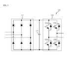
FIG.2 is a configurative view illustrating a unit power cell ofFIG.1 . Referring toFIG.2 , the unit power cell (120) includes a 3-phase diode rectifier (121), a DC-link capacitor (122) and an inverter (123). The 3-phase diode rectifier (121) outputs a 3-phase rectified DC voltage using an output voltage of the phase switching transformer (110) as an input. The DC-link capacitor (122) stores the input power of the 3-phase diode rectifier (121). The inverter (123) is a single phase full bridge inverter to synthesize output voltages via switching of the switching elements (123a∼123d) using the voltages received from the DC-link capacitor (122). - Now, system of
FIGS. 1 and2 will be described. - The phase switching transformer (110) converts a phase and size of a high voltage input power catering to requirement of the unit power cell (120). An output voltage of the phase switching transformer (110) becomes of an input power of each unit power cell (120) and is converted to a DC through the 3-phase diode rectifier (121) of
FIG.2 . The DC-link capacitor (122) serves to constantly maintain the output voltage of the 3-phase diode rectifier (121). - The single phase full bridge inverter (123) synthesizes the AC output voltages with the voltages from the DC-link capacitor (122). IF the voltage of the DC-link capacitor (122) is assumed as 'E', an output voltage of the inverter (123) would be shown as 'E', 'O' and '-E' according to switching state.
- For a non-limiting example, if 123a and 123d are electrically conducted, the synthesized output voltage is 'E', and if 123b and 123c are electrically conducted, the synthesized output voltage is '-E', if 123a and 123c, or 123b and 123d are electrically conducted, the synthesized output voltage is '0'.
- In the unit power cell structure of
FIG. 1 , output voltages of A1, A2, A3, B1, B2, B3 and C1, C2, C3 are all serially connected, such that serially connected output phase voltages are synthesized in 7 steps of '3E', '2E', 'E', '0', '-E', '-2E, and '-3E'. An output line-to-line voltage of the motor from the synthesized output phase voltages may be synthesized in 13 steps of '6E', '5E', '4E', '3E', '2E', 'E', '0', '-E', '-2E', '-3E', '-4E', '-5E', '-6E', which may be generalized as below.

where, m is a level number of output phase voltage, H is the number of unit power cells (120) installed at each phase of motor (300), and p is the level number of output line-to-line voltages. - Meanwhile, with an output of each unit power cell (120) being an output of a single full bridge inverter, an output of a DC-link power is formed with a voltage ripple. First, an output voltage and an output current of each cell are defined as under.


where, φ is a load angle, ω is an operating frequency, t is time, VO and Io are an output voltage and an rms value of an output current. An output power of unit power cell (120) can be obtained as below based on theEquations 3 and 4.
- As noted from the Equation 5, it can be learned that an output of unit power cell (120) is divided to a DC component of VoIo cosφ and an AC component of VoIo cos(2ωt - φ), where the AC component has a ripple corresponding to twice that of the operating frequency. Now, a current flowing in DC link can be obtained as below.

- Based on the Equations 5 and 6, it can be learned that the DC link is generated with a ripple twice tht of the operating frequency.
The conventional series H-bridge medium voltage inverter thus described suffers from a disadvantage in that, because it is formed with a diode rectifier for an input terminal of a unit power cell, it is impossible to perform a regenerative operation to make it difficult to perform a fast acceleration or a fast deceleration. As a result, the conventional series H-bridge medium voltage inverter thus described has a disadvantage of taking a long time for decelerated operation during a decelerated operation. Another disadvantage is that each capacitance of DC-link capacitor of all unit power cells must be enlarged to increase the size of an entire system.
Thus, there is a need to address the abovementioned disadvantages. - This section provides a general summary of the disclosure, and is not a comprehensive disclosure of its full scope or all of its features.
- The present disclosure is provided to solve the aforementioned disadvantages and it is an object of the present disclosure to provide a partial regenerative medium voltage inverter configured to combine a conventional series H-bridge medium voltage inverter with a regenerative unit power cell having an active rectifier capable of performing a regenerative operation.
It should be emphasized, however, that the present disclosure is not limited to a particular disclosure, as explained above. It should be understood that other technical subjects not mentioned herein may be appreciated by those skilled in the art. - In one general aspect of the present disclosure, there is provided a regenerative medium voltage inverter, the inverter comprising: a plurality of power cells configured to transmit, by serially-connected three groups, a phase voltage to a motor; a plurality of input filters interconnected between an input power unit and the power cell to reduce harmonics of a 3-phase input power; and a plurality of switching signal generating units interconnected between an input power unit and the power cell to switch a voltage inputted to the power cell.
Preferably, but not necessarily, the inverter further comprises a phase switching transformer electrically insulating the input power from the input power unit and providing the electrically insulated input power to each of the plurality of power cells.
Preferably, but not necessarily, the input filter is mounted with three input terminals receiving the input power, and comprises inductors respectively connected to the input terminals, and capacitors connected with the inductors in a delta connection. - Preferably, but not necessarily, the input filter further comprises resistors connected in parallel to each of the inductors to remove resonance of the input power.
Preferably, but not necessarily, the power cell comprises an active rectifying unit receiving an output voltage of the input filter to output a DC (direct current) voltage rectified from the output voltage, a DC-link capacitor storing the DC voltage, and an inverter unit synthesizing output voltage from the stores DC voltage.
Preferably, but not necessarily, the active rectifying unit comprises a plurality of switches connected in parallel to each phase voltage.
Preferably, but not necessarily, the switching signal generating unit controls the plurality of switches to sequentially connect the power cell and the input power unit.
Preferably, but not necessarily, each of the switches comprises a transistor and a diode that are connected in parallel.
Preferably, but not necessarily, the switching signal generating unit measures a line-to-line voltage using the input power from the input power unit, extracts a power angle using the measured line-to-line voltage and switches the voltage inputted to the power cell.
The regenerative medium voltage inverter according to exemplary embodiments of the present disclosure has an advantageous effect in that regenerative operation is enabled by changing structure of input terminal of a unit power cell at a series H-bridge medium voltage inverter, and a dynamic braking resistor is not required to reduce the size of a DC-link capacitor over that of a conventional medium voltage inverter. - In order to explain the principle of the present disclosure, some accompanying drawings related to its preferred embodiments are below reported for the purpose of illustration, exemplification and description, although they are not intended to be exhaustive. The drawing figures depict one or more exemplary embodiments in accord with the present concepts, by way of example only, not by way of limitations. In the figures, like reference numerals refer to the same or similar elements.
- Thus, a wide variety of potential practical and useful embodiments will be more readily understood through the following detailed description of certain exemplary embodiments, with reference to the accompanying exemplary drawings in which:
-
FIG. 1 is a structural view illustrating a series H-bridge medium voltage inverter according to prior art; -
FIG.2 is a structural view illustrating a unit power cell ofFIG.1 ; -
FIG.3 is a structural view illustrating a regenerative medium voltage inverter according to an exemplary embodiment of the present disclosure; -
FIG.4 is a detailed structural view illustrating an input filter ofFIG.3 according to an exemplary embodiment of the present disclosure; -
FIG.5 is a detailed structural view illustrating an input filter ofFIG.3 according to another exemplary embodiment of the present disclosure; -
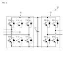
FIG.6 is a detailed structural view illustrating a power cell ofFIG.3 according to an exemplary embodiment of the present disclosure; -
FIG.7 is a schematic view illustrating an input filter connected to a power cell in -
FIG.3 and a switching signal generating unit; and -
FIG.8 is a schematic view illustrating a switching signal generated by the switching signal generating unit ofFIG.3 and a resultant switching of an active rectifying unit according to an exemplary embodiment of the present disclosure. - The disclosed embodiments and advantages thereof are best understood by referring to
FIGS. 1-8 of the drawings, like numerals being used for like and corresponding parts of the various drawings. Other features and advantages of the disclosed embodiments will be or will become apparent to one of ordinary skill in the art upon examination of the following figures and detailed description. It is intended that all such additional features and advantages be included within the scope of the disclosed embodiments, and protected by the accompanying drawings. Further, the illustrated figures are only exemplary and not intended to assert or imply any limitation with regard to the environment, architecture, or process in which different embodiments may be implemented. Accordingly, the described aspect is intended to embrace all such alterations, modifications, and variations that fall within the scope and novel idea of the present invention. - Meanwhile, the terminology used herein is for the purpose of describing particular implementations only and is not intended to be limiting of the present disclosure. The terms "first," "second," and the like, herein do not denote any order, quantity, or importance, but rather are used to distinguish one element from another. For example, a second constituent element may be denoted as a first constituent element without departing from the scope and spirit of the present disclosure, and similarly, a first constituent element may be denoted as a second constituent element.
- As used herein, the terms "a" and "an" herein do not denote a limitation of quantity, but rather denote the presence of at least one of the referenced item. That is, as used herein, the singular forms "a", "an" and "the" are intended to include the plural forms as well, unless the context clearly indicates otherwise.
- It will be understood that when an element is referred to as being "connected" or "coupled" to another element, it can be directly connected or coupled to the other element or intervening elements may be present. In contrast, when an element is referred to as being "directly connected" or "directly coupled" to another element, there are no intervening elements present.
- It will be further understood that the terms "comprises" and/or "comprising," or "includes" and/or "including" when used in this specification, specify the presence of stated features, regions, integers, steps, operations, elements, and/or components, but do not preclude the presence or addition of one or more other features, regions, integers, steps, operations, elements, components, and/or groups thereof.
- Also, "exemplary" is merely meant to mean an example, rather than the best. If is also to be appreciated that features, layers and/or elements depicted herein are illustrated with particular dimensions and/or orientations relative to one another for purposes of simplicity and ease of understanding, and that the actual dimensions and/or orientations may differ substantially from that illustrated.
- That is, in the drawings, the size and relative sizes of layers, regions and/or other elements may be exaggerated or reduced for clarity. Like numbers refer to like elements throughout and explanations that duplicate one another will be omitted. As may be used herein, the terms "substantially" and "approximately" provide an industry-accepted tolerance for its corresponding term and/or relativity between items.
- Hereinafter, a regenerative medium voltage inverter according to the present disclosure will be described in detail with reference to the accompanying drawings.
-
FIG.3 is a structural view illustrating a regenerative medium voltage inverter according to an exemplary embodiment of the present disclosure, where a series H-bridge medium voltage inverter is exemplified. - However, it should be apparent to the skilled in the art that, although the regenerative medium voltage inverter configured with a 3-level unit power cell is exemplified, the present disclosure is not limited thereto, and the number of unit power cells may be changed as required.
- A regenerative medium voltage inverter (10) according to the present disclosure is an inverter that receives a voltage, whose rms (root mean square) value is over 600V in line-to-line voltage, from an input power unit (20) and supplies a 3-phase power to a motor (30). Preferably, the motor (30) is an induction motor or a synchronous motor but is not limited thereto.
- Referring to
FIG.3 , the regenerative medium voltage inverter (10) includes a phase shift transformer (11), a plurality of input filters (12), a plurality of switching signal generating units (13) and a plurality of power cells (14).FIG.3 exemplifies a 3-level unit power cell, such that the number of power cells (14) providing the 3-phase voltage to the motor (30) totals 9, and the number of input filters (12) and the switching signal generating units (13), being respectively connected to the power cells (14), totals 9 respectively in the present disclosure. However, it should be apparent to the skilled in the art that those numbers may be changed according to the number of power cells (14).
Although only one switching signal generating unit (13) is illustrated as transmitting signal to A1 inFIG.3 for convenience sake, it is not limited thereto and it should be apparent that the switching signal generating unit (13) is mounted to each of the power cells.
The phase shift transformer (11) serves to provide an electrical insulation between the input power unit (20) and the regenerative medium voltage inverter (10), to reduce harmonics from the input power and to provide a 3-phase power to each power cell (14). The input filter (12) functions to reduce harmonics from the input power.
FIG.4 is a detailed structural view illustrating an input filter ofFIG.3 according to an exemplary embodiment of the present disclosure, andFIG.5 is a detailed structural view illustrating an input filter ofFIG.3 according to another exemplary embodiment of the present disclosure. - Referring to
FIG.4 , the input filter (12) includes inductors (41a∼41c) respectively connected in series to the 3-phase output of secondary winding side of the phase shift transformer (11) {To this end, the input filter (12) is formed with three input terminals}, and capacitors (42a∼42c) connected to the inductors (41a∼41c) in a delta connection. - Now, referring to
FIG.5 , the input filter (12) according to another exemplary embodiment of the present disclosure includes inductors (51a∼51c) respectively connected in series to the 3-phase output of secondary winding side of the phase shift transformer (11) {To this end, the input filter (12) is formed with three input terminals}, capacitors (52a∼52c) connected to the inductors (51a∼51c) in delta connection, and damping resistors (53a∼53c) respectively connected in parallel to the inductors (51a∼51c). The damping resistors (53a∼53c) serve to remove resonance in the input voltage, if the resonance is generated in the input voltage. - The unit power cell (14) functions to output a phase voltage of the motor (30), and each unit power cell (14) is formed with three groups that are connected in series. In
FIG.3 , A1, A2 and A3 are serially connected at output voltages to synthesize 'a' phase voltage of the motor (30), B1, B2 and B3 are serially connected at output voltages to synthesize 'b' phase voltage of the motor (30), and C1, C2 and C3 are serially connected at output voltages to synthesize 'c' phase voltage of the motor (30). The synthesized 'b'phase and 'a'phase voltages have a 120° phase difference, and the synthesized 'c'phase and 'b'phase voltages also have a 120° phase difference.
FIG.6 is a detailed structural view illustrating a power cell ofFIG.3 according to an exemplary embodiment of the present disclosure, where each of the plurality of power cells (14) has the same structure. - Referring to
FIG.6 , the power cell (14) includes an active rectifying unit (61), a DC-link capacitor (62) and an inverter unit (63). - An input of the active rectifying unit (61) is an output voltage of the input filter (12) of
FIG. 3 , from which a DC rectified from the 3-phase voltage is outputted. The active rectifying unit (61) includes six transistor switches (hereinafter referred to as switch, 61a∼61f), where the transistor is preferably an IGBT (Insulated Gate Bipolar Transistor), as shown inFIG.6 . The DC-link capacitor (62) stores an input power of the active rectifying unit (61). - The inverter unit (63) is preferably a single phase full bridge inverter to synthesize output voltages form a voltage of the DC link in response to control of a controller (not shown). The inverter unit (63) includes four switches (63a∼63d), and each switch is formed by connecting in parallel a transistor and a diode. Now, a circuit of
FIG. 3 will be described in detail with an emphasis on a difference from that ofFIG.1 . - First, the input filter (12) of
FIG.3 configured as inFIG.4 orFIG.5 receives an output of the phase shift transformer (11), and inductances of inductors (41a∼41c or 51a∼51c) at the input filter (12) are sufficiently greater in value than those of leakage inductance of the phase shift transformer (11).
where, Lfilter is an inductance of inductors (41a∼41c or 51a∼51c) at the input filter (12), and L leakage_2nd is a leakage inductance of the phase shift transformer (11) converted to a secondary winding side. Furthermore, capacitance of capacitors (42a∼42c or 52a∼52c) ofFIG.4 orFIG.5 may be obtained from the following relations.
where, ω c is a cut-off frequency of input filter (12), and has a value six times greater than an input power frequency.
where, ω source is an input power frequency. - Meanwhile, a resistance having a maximum damping relative to damping resistors (53a∼53c) of
FIG.5 is as under.
- An input line-to-line voltage measured by the input filter (12) determines the switching of the active rectifying unit of
FIG.6 , where a measured position of the voltage is situated between the phase shift transformer (11) and the input filter (12). -
FIG.7 is a schematic view illustrating an input filter connected to a power cell inFIG.3 and a switching signal generating unit. - The switching signal generating unit (13) serves to generate a switching signal of the active rectifying unit (61). That is, the switching signal generating unit (13) measures an input line-to-line voltage from the 3-phase voltage inputted from the input filter (12), extracts an input power angle from the measured line-to-line voltage and transmits a gating signal, i.e., a switching signal to six transistors (61a∼61f) of the active rectifying unit (61).
-
FIG.8 is a schematic view illustrating a switching signal generated by the switching signal generating unit ofFIG.3 and a resultant switching of an active rectifying unit according to an exemplary embodiment of the present disclosure, where the switching signal generated by the switching signal generating unit ofFIG.3 in response to an input line-to-line voltage is exemplified. - Referring to
FIG. 8 , 'Vab' represents an ab line-to-line voltage, 'Vbc' represents a bc line-to-line voltage and 'Vca' represents a ca line-to-line voltage, and the switching signal generating unit (13) transmits ON/OFF signals relative to switches (61a∼61f) of the active rectifying unit (61) to each switch (61a∼61f) of the transistors.
Referring toFIG. 8 , it can be noted that the switching of the active rectifying unit has a same switching frequency as frequency of the input power. - That is, in a case the input power angle of ω t is from 0 to π/3, switches of 61d and 61e of
FIG. 6 are turned on, in a case the input power angle is from π/3 to 2π/3, switches of 61a and 61d are turned on, and in a case the input power angle is from 2π/3 to π, switches of 61a and 61f are turned on. - Furthermore, in a case the input power angle is from π to 4π/3, switches of 61c and 61f are turned on, in a case the input power angle is from 4π/3 to 5π/3, switches of 61b and 61c are turned on, and in a case the input power angle is from 5π/3 to 2π, switches of 61b and 61e are turned on.
- The switching pattern is periodically repeated at every 2π in response to changes in input power angle, by which the power cell (14) including the active rectifying unit (61) is enabled for bi-directional power transmission.
- Although
FIG. 8 has illustrated the switching of the active rectifying unit (61) relative to the input line-to-line voltage, it should be apparent to the skilled in the art that an identical operation can be made by measuring an input phase voltage, which will be explained later. - The following represents relationship between an input line-to-line voltage and an input phase voltage.


- In the
above Equations FIG. 8 may be also applied to the phase voltage, because the phase voltage can be obtained from the line-to-line voltage. - By the switching of the switching signal generating unit (13), the active rectifying unit (61) is such that the switches (61a∼61f) are operated at a point same as that of diode of the diode rectifying unit (21) being operated, whereby the phase shift transformer (11) and the power cell (14) are electrically and instantaneously connected to enable a regenerative operation.
- In a case the phase shift transformer (11) and the power cell (14) are connected by the switching of
FIG. 8 , the following relationship occurs. - First, 'a' output voltage and current of a motor (30) may be defined by the following
equations 14 and 15 respectively, and 'b' and 'c' output voltages and currents of the motor (30) may be also defined by the following equations 16, 17, 18 and 19 respectively.


where, φ is a load angle, ω is an operating frequency, t is time, Vo and Io are rms values of output voltage and output current. - From
Equations 14 and 15, power generated from 'a' phase of motor (30) can be obtained from the followingEquation 20, and likewise, powers generated from 'b' phase and 'c' phase can be obtained from Equations 21 and 22.


- Thus, size of entire power is shown only in DC components as shown in the following.

- That is, as in Equation 23, according to the active rectifying unit (61) of the present disclosure, the phase shift transformer (11) and the power cell (14) are instantaneously connected to allow a system to output a predetermined power, whereby a DC-link capacitor of unit power cell (14) can be reduces in size over that of the conventional medium voltage inverter.
- The unit power cell having the conventional diode rectifying unit as shown in
FIGS.1 and2 has a ripple twice the operating frequency in the power outputted by each unit power cell as shown inEquations 20, 21 and 22. There is a disadvantage of enlarging the size of a DC-link capacitor of the unit power cell in order to reduce the ripple. - However, the power cell (14) including the active rectifying unit (61) according to the present disclosure can advantageously reduce the size of the DC-link capacitor of each power cell (14), because an input terminal and an output terminal are instantaneously connected, a ripple power is not concentrated in the DC-link capacitor of each unit power cell, and a sum of 3-phase powers is available only in DC components as shown in Equation 23.
- Although the present disclosure has been described with reference to a number of illustrative embodiments thereof, it should be understood that numerous other modifications and embodiments can be devised by those skilled in the art that will fall within the spirit and scope of the principles of this disclosure.
- More particularly, various variations and modifications are possible in the component parts and/or arrangements of subject combination arrangement within the scope of the disclosure, the drawings and the appended claims. In addition to variations and modifications in the component parts and/or arrangements, alternative uses will also be apparent to those skilled in the art.
- The regenerative medium voltage inverter according to exemplary embodiments of the present disclosure have an industrial applicability in that regenerative operation is enabled by changing structure of input terminal of a unit power cell at a series H-bridge medium voltage inverter, and a dynamic braking resistor is not required to reduce the size of a DC-link capacitor over that of a conventional medium voltage inverter.
Claims (9)
- A regenerative medium voltage inverter (10) outputting a 3-phase input power from an input power unit (20) to a motor (30), the inverter (10) characterized by:a plurality of power cells (14) configured to transmit, by serially-connected three groups, a phase voltage to the motor (30);a plurality of input filters (12) interconnected between the input power unit (20) and the power cell (14) to reduce harmonics of the input power; anda plurality of switching signal generating units (13) interconnected between the input power unit (20) and the power cell (14) to switch a voltage inputted to the power cell (14).
- The inverter of claim 1, further characterized by: a phase switching transformer (11) electrically insulating the input power from the input power unit (20) and providing the electrically insulated input power to each of the plurality of power cells (14).
- The inverter of claim 1 or 2, characterized in that the input filter (12) is mounted with three input terminals receiving a 3-phase input power, and comprises inductors (41a to 41c, 51a to 51c) respectively connected to the input terminals, and capacitors (42a to 42c, 52a to 52c) connected with the inductors (41a to 41c, 51a to 51c) in a delta connection.
- The inverter of claim 3, characterized in that the input filter (12) further comprises resistors (53a to 53c) connected in parallel to each of the inductors (41a to 41c, 51a to 51c) to remove resonance of the input power.
- The inverter of any one of claims 1 to 4, characterized in that the power cell (14) comprises an active rectifying unit (61) receiving an output voltage of the input filter (12) to output a DC (direct current) voltage rectified from the output voltage, a DC-link capacitor (62) storing the DC voltage, and an inverter unit (63) synthesizing output voltage from the stored DC voltage.
- The inverter of claim 5, characterized in that the active rectifying unit (61) comprises a plurality of switches (61a to 61f) connected in parallel to each phase voltage.
- The inverter of claim 6, characterized in that the switching signal generating unit (61) controls the plurality of switches (61a to 61f) to sequentially connect the power cell (14) and the input power unit (20).
- The inverter of claim 6 or 7, characterized in that each of the switches (61a to 61f) comprises a transistor and a diode that are connected in parallel.
- The inverter of any one of claims 1 to 8, characterized in that the switching signal generating unit (13) measures a line-to-line voltage using the input power from the input power unit (20), extracts a power angle using the measured line-to-line voltage and switches the voltage inputted to the power cell.
Applications Claiming Priority (1)
| Application Number | Priority Date | Filing Date | Title |
|---|---|---|---|
| KR1020110104296A KR20130039612A (en) | 2011-10-12 | 2011-10-12 | Regenerative medium voltage inverter |
Publications (2)
| Publication Number | Publication Date |
|---|---|
| EP2582032A2 true EP2582032A2 (en) | 2013-04-17 |
| EP2582032A3 EP2582032A3 (en) | 2014-05-28 |
Family
ID=46940258
Family Applications (1)
| Application Number | Title | Priority Date | Filing Date |
|---|---|---|---|
| EP12181824.9A Withdrawn EP2582032A3 (en) | 2011-10-12 | 2012-08-27 | Cascaded H-bridge multicell medium voltage converter with bidirectional infeeds for the cells |
Country Status (5)
| Country | Link |
|---|---|
| US (1) | US8922151B2 (en) |
| EP (1) | EP2582032A3 (en) |
| JP (1) | JP2013085453A (en) |
| KR (1) | KR20130039612A (en) |
| CN (1) | CN103051283B (en) |
Cited By (3)
| Publication number | Priority date | Publication date | Assignee | Title |
|---|---|---|---|---|
| EP3045343A1 (en) * | 2015-01-16 | 2016-07-20 | ALSTOM Transport Technologies | A convertor for electric feeder and/or substation for recuperating the braking energy |
| US9455651B2 (en) | 2014-12-16 | 2016-09-27 | Caterpillar Inc. | Motor driver having integrated braking chopper |
| WO2022216279A1 (en) * | 2021-04-07 | 2022-10-13 | Siemens Aktiengesellschaft | Regenerative multicell drive system with overlap angle in fundamental frequency modulation |
Families Citing this family (11)
| Publication number | Priority date | Publication date | Assignee | Title |
|---|---|---|---|---|
| FR2982092B1 (en) * | 2011-11-02 | 2015-01-02 | Valeo Systemes De Controle Moteur | POWER MODULE AND ELECTRIC DEVICE FOR POWER SUPPLY AND CHARGING COMBINED WITH ACCUMULATOR AND MOTOR |
| US9722503B2 (en) * | 2013-03-28 | 2017-08-01 | Teco-Westinghouse Motor Company | Modular configurable multi-megawatt power amplifier |
| US9654021B2 (en) * | 2013-10-09 | 2017-05-16 | Rockwell Automation Technologies, Inc. | Multifunction power converter with option for integrated magnetics |
| US10629396B2 (en) | 2017-05-08 | 2020-04-21 | Rockwell Automation Technologies, Inc. | Arc flash resistant enclosure with segregated cooling |
| US10011178B1 (en) * | 2017-06-08 | 2018-07-03 | Ford Global Technologies, Llc | DC inverter having reduced switching loss and reduced voltage spikes |
| US11038436B2 (en) * | 2017-09-25 | 2021-06-15 | Lsis Co., Ltd. | Inverter system |
| CN113261194B (en) * | 2019-01-04 | 2025-04-08 | 茵梦达有限责任公司 | Reducing Input Harmonic Distortion in Power Supplies |
| US10651760B1 (en) * | 2019-04-24 | 2020-05-12 | Rockwell Automation Technologies, Inc | Reduced semiconductor device power cell voltage drive |
| US10924025B2 (en) | 2019-04-24 | 2021-02-16 | Rockwell Automation Technologies, Inc. | Regenerative cascaded H bridge power supply |
| DE102020104252A1 (en) * | 2019-05-21 | 2020-11-26 | Vacon Oy | Power converter |
| JP7514778B2 (en) * | 2021-02-05 | 2024-07-11 | 株式会社豊田中央研究所 | Power System |
Family Cites Families (17)
| Publication number | Priority date | Publication date | Assignee | Title |
|---|---|---|---|---|
| US4445167A (en) * | 1981-10-05 | 1984-04-24 | Tokyo Shibaura Denki Kabushiki Kaisha | Inverter system |
| FR2610153B1 (en) * | 1987-01-28 | 1989-04-07 | Merlin Gerin | DISSIPATIVE LOW PASS FILTER |
| US5625545A (en) * | 1994-03-01 | 1997-04-29 | Halmar Robicon Group | Medium voltage PWM drive and method |
| US6014323A (en) * | 1997-08-08 | 2000-01-11 | Robicon Corporation | Multiphase power converter |
| US5990654A (en) * | 1998-01-21 | 1999-11-23 | Allen-Bradley Company, Llc | Apparatus for eliminating motor voltage reflections and reducing EMI currents |
| JP2000268756A (en) * | 1999-03-12 | 2000-09-29 | Toshiba Corp | Charged beam device and charged beam control method |
| US6847531B2 (en) * | 2001-01-02 | 2005-01-25 | General Electric Company | System and method for regenerative PWM AC power conversion |
| US7088073B2 (en) * | 2003-01-24 | 2006-08-08 | Toshiba Internationl Corporation | Inverter drive system |
| JP2005348573A (en) | 2004-06-07 | 2005-12-15 | Toshiba Mitsubishi-Electric Industrial System Corp | Power converter |
| DE102005005688A1 (en) * | 2005-02-08 | 2006-08-10 | Siemens Ag | Filter for backfeedable rectifier, has capacitor connected at each connection point of winding portions, which are arranged on common core in such a manner that their ampere turns mutually compensate during flow |
| JP4609102B2 (en) | 2005-02-15 | 2011-01-12 | 株式会社明電舎 | Series multiple inverter device |
| US7508147B2 (en) | 2005-05-19 | 2009-03-24 | Siemens Energy & Automation, Inc. | Variable-frequency drive with regeneration capability |
| EP1884015B1 (en) * | 2005-05-27 | 2011-06-29 | Siemens Industry, Inc. | Inverter operation with over-modulation |
| RU2388133C2 (en) | 2005-09-09 | 2010-04-27 | Сименс Энерджи Энд Отомейшн, Инк. | System and method for reduction of harmonics effect at system of energy delivery |
| JP4849310B2 (en) | 2005-10-28 | 2012-01-11 | 富士電機株式会社 | AC / AC power converter controller |
| JP2009106081A (en) | 2007-10-23 | 2009-05-14 | Mitsubishi Heavy Ind Ltd | Power converter |
| JP5230207B2 (en) | 2008-01-07 | 2013-07-10 | 三菱重工業株式会社 | Bidirectional power converter and control method thereof |
-
2011
- 2011-10-12 KR KR1020110104296A patent/KR20130039612A/en not_active Ceased
-
2012
- 2012-08-27 EP EP12181824.9A patent/EP2582032A3/en not_active Withdrawn
- 2012-09-14 US US13/615,608 patent/US8922151B2/en active Active
- 2012-09-19 JP JP2012206014A patent/JP2013085453A/en active Pending
- 2012-10-12 CN CN201210387267.1A patent/CN103051283B/en not_active Expired - Fee Related
Non-Patent Citations (1)
| Title |
|---|
| "Leistungselektronische Schaltungen: Funktion, Auslegung und Anwendung", 26 October 2012, SPRINGER-VERLAG, ISBN: 978-3-642-30104-9, article DIRK SCHRÖDER: "Leistungselektronische Schaltungen: Funktion, Auslegung und Anwendung", pages: 604 - 607, XP055466935 * |
Cited By (7)
| Publication number | Priority date | Publication date | Assignee | Title |
|---|---|---|---|---|
| US9455651B2 (en) | 2014-12-16 | 2016-09-27 | Caterpillar Inc. | Motor driver having integrated braking chopper |
| EP3045343A1 (en) * | 2015-01-16 | 2016-07-20 | ALSTOM Transport Technologies | A convertor for electric feeder and/or substation for recuperating the braking energy |
| FR3031849A1 (en) * | 2015-01-16 | 2016-07-22 | Alstom Transp Tech | POWER SUPPLY CONVERTER AND / OR SUBSTATION FOR RECOVERING BRAKING ENERGY |
| US10554117B2 (en) | 2015-01-16 | 2020-02-04 | Alstom Transport Technologies | Convertor for electric feeder and/or substation for recuperating the braking energy |
| WO2022216279A1 (en) * | 2021-04-07 | 2022-10-13 | Siemens Aktiengesellschaft | Regenerative multicell drive system with overlap angle in fundamental frequency modulation |
| AU2021439254B2 (en) * | 2021-04-07 | 2024-09-19 | Innomotics Gmbh | Regenerative multicell drive system with overlap angle in fundamental frequency modulation |
| US12539764B2 (en) | 2021-04-07 | 2026-02-03 | Innomotics Gmbh | Regenerative multicell drive system with overlap angle in fundamental frequency modulation |
Also Published As
| Publication number | Publication date |
|---|---|
| US8922151B2 (en) | 2014-12-30 |
| US20130093376A1 (en) | 2013-04-18 |
| EP2582032A3 (en) | 2014-05-28 |
| CN103051283B (en) | 2016-02-17 |
| KR20130039612A (en) | 2013-04-22 |
| JP2013085453A (en) | 2013-05-09 |
| CN103051283A (en) | 2013-04-17 |
Similar Documents
| Publication | Publication Date | Title |
|---|---|---|
| US8922151B2 (en) | Regenerative medium voltage inverter | |
| US10924031B2 (en) | Internal paralleled active neutral point clamped converter with logic-based flying capacitor voltage balancing | |
| US9337746B2 (en) | Multilevel inverter | |
| US9331595B2 (en) | Multi-level inverter | |
| CN103503268B (en) | Wind energy converter | |
| US9054600B2 (en) | Control apparatus for regenerative medium voltage inverter | |
| CA2565707C (en) | Low harmonics, polyphase converter circuit | |
| EP3068029A1 (en) | Inverter system | |
| US11949348B2 (en) | Bi-directional line-interphase transformer-based converter | |
| JP2014018015A (en) | Control device and control method of voltage type power conversion apparatus | |
| JP2016537954A (en) | Inverter including a switch between a midpoint of a DC intermediate circuit and a neutral conductor terminal of an AC grid and method of operating the inverter | |
| JP2011130517A (en) | Power converter | |
| US20150008856A1 (en) | Multi-level medium-voltage inverter | |
| JP2015006077A (en) | Power conversion apparatus having power storage device thereon | |
| CN104734528B (en) | Polyphase electric power driver and its power cell | |
| US20080247211A1 (en) | Active generator control sequence | |
| RU2600125C2 (en) | Converter and method of its operation to convert voltages | |
| JP3899850B2 (en) | Power supply | |
| US20050078497A1 (en) | Three phase isolated vector switching AC to AC frequency converters | |
| Jin et al. | Control and modulation of the stacked polyphase bridges inverter | |
| Dutta | Some aspects on 3-phase bridge inverter (180 degree mode) | |
| CN101860233B (en) | Method for running converter circuit and device for performing the same | |
| KR20130039610A (en) | Partial regenerative medium voltage inverter | |
| Nikouie et al. | Operation under fault conditions of the stacked polyphase bridges converter | |
| EP4633021A1 (en) | Electrical power system |
Legal Events
| Date | Code | Title | Description |
|---|---|---|---|
| PUAI | Public reference made under article 153(3) epc to a published international application that has entered the european phase |
Free format text: ORIGINAL CODE: 0009012 |
|
| AK | Designated contracting states |
Kind code of ref document: A2 Designated state(s): AL AT BE BG CH CY CZ DE DK EE ES FI FR GB GR HR HU IE IS IT LI LT LU LV MC MK MT NL NO PL PT RO RS SE SI SK SM TR |
|
| AX | Request for extension of the european patent |
Extension state: BA ME |
|
| PUAL | Search report despatched |
Free format text: ORIGINAL CODE: 0009013 |
|
| AK | Designated contracting states |
Kind code of ref document: A3 Designated state(s): AL AT BE BG CH CY CZ DE DK EE ES FI FR GB GR HR HU IE IS IT LI LT LU LV MC MK MT NL NO PL PT RO RS SE SI SK SM TR |
|
| AX | Request for extension of the european patent |
Extension state: BA ME |
|
| RIC1 | Information provided on ipc code assigned before grant |
Ipc: H02M 1/12 20060101ALI20140422BHEP Ipc: H02M 7/49 20070101AFI20140422BHEP Ipc: H02M 5/458 20060101ALI20140422BHEP |
|
| 17P | Request for examination filed |
Effective date: 20141128 |
|
| RBV | Designated contracting states (corrected) |
Designated state(s): AL AT BE BG CH CY CZ DE DK EE ES FI FR GB GR HR HU IE IS IT LI LT LU LV MC MK MT NL NO PL PT RO RS SE SI SK SM TR |
|
| 17Q | First examination report despatched |
Effective date: 20161017 |
|
| STAA | Information on the status of an ep patent application or granted ep patent |
Free format text: STATUS: THE APPLICATION IS DEEMED TO BE WITHDRAWN |
|
| 18D | Application deemed to be withdrawn |
Effective date: 20190528 |