EP2581956A2 - Schaltanordnung für Supraleiter - Google Patents
Schaltanordnung für Supraleiter Download PDFInfo
- Publication number
- EP2581956A2 EP2581956A2 EP20120185884 EP12185884A EP2581956A2 EP 2581956 A2 EP2581956 A2 EP 2581956A2 EP 20120185884 EP20120185884 EP 20120185884 EP 12185884 A EP12185884 A EP 12185884A EP 2581956 A2 EP2581956 A2 EP 2581956A2
- Authority
- EP
- European Patent Office
- Prior art keywords
- superconductor
- superconducting
- switching arrangement
- connection zones
- connection
- Prior art date
- Legal status (The legal status is an assumption and is not a legal conclusion. Google has not performed a legal analysis and makes no representation as to the accuracy of the status listed.)
- Granted
Links
Images


Classifications
-
- H—ELECTRICITY
- H10—SEMICONDUCTOR DEVICES; ELECTRIC SOLID-STATE DEVICES NOT OTHERWISE PROVIDED FOR
- H10N—ELECTRIC SOLID-STATE DEVICES NOT OTHERWISE PROVIDED FOR
- H10N60/00—Superconducting devices
- H10N60/30—Devices switchable between superconducting and normal states
- H10N60/35—Cryotrons
- H10N60/355—Power cryotrons
-
- H—ELECTRICITY
- H03—ELECTRONIC CIRCUITRY
- H03K—PULSE TECHNIQUE
- H03K17/00—Electronic switching or gating, i.e. not by contact-making and –breaking
- H03K17/51—Electronic switching or gating, i.e. not by contact-making and –breaking characterised by the components used
- H03K17/92—Electronic switching or gating, i.e. not by contact-making and –breaking characterised by the components used by the use, as active elements, of superconductive devices
Definitions
- This invention relates to a superconductor switching arrangement.
- this invention relates to a superconducting switching arrangement for rectifying and inverting alternating and direct currents. It also relates to a switching arrangement for use in a transformer and as a fault current limiter.
- One such technology is the creation of a superconducting system to provide the electrical power to the fan units so as to try and reduce the weight of the electrical system.
- a superconductor conducts electricity without loss, that is, with zero electrical resistance.
- current state of the art superconductor materials must be maintained below a critical temperature, current density and magnetic field. If any of the critical limits are exceeded then the superconductor is said to "quench”, at which point it reverts to its "normal” electrical (and magnetic) properties.
- the quenched electrical resistance can be very high.
- FIG. 1 shows the basic concept for a cryotron 10 which uses an electrical coil 12 wrapped around a length of superconductor 14.
- the superconductor current, Ig flows until an electrical current, Ic, of sufficient magnitude to produce a quenching magnetic field flows through the electrical coil 12. Once this occurs, the resistance increases until there is negligible current flow, thereby providing a switch.
- the present invention seeks to provide a superconducting switch of general application but which may preferably be used in a distributed propulsion system of an aircraft.
- the present invention provides a superconductor switching arrangement, comprising: a superconductor having a plurality of first connection zones and at least one second connection zones, the first and second connection zones being connectable by at least one superconducting path in use, a quenching device which is operable to selectively quench regions of the superconductor so as to remove the superconducting path between at least two of the first connection zones and the at least one second connection zone.
- Having a superconducting path which can be switched between two of first connections zones allows a sliding superconducting path to be passed across the superconductor and helps avoid power dissipation which may occur if each region was switched off discretely.
- the quenching device may include at least one magnetic flux source configured to provide a critical magnetic field to the superconductor.
- the quenching device may further comprise at least one electromagnetic coil which is switchable to modify the magnetic field provided to the superconductor in use.
- the quenching device may be arranged so as to provide a conductive path between two adjacent first connection zones and a second connection zone.
- the electromagnetic coil may include a superconductor.
- the quenching device may be configurable to provide a superconducting path between at least two of the plurality of first connection zones.
- the superconductor may be a monolithic homogeneous body.
- the superconductor switching arrangement may further comprise dielectric barriers between each of the plurality of first connection zones.
- the superconducting body may be cylindrical.
- the quenching device may be configured to provide a radial magnetic field.
- the quenching device may be configured to provide an axial magnetic field.
- the quenching device may include at least one poly phase winding which is configured to provide a rotating magnetic field in use.
- the superconducting switching arrangement may have at least two second connection zones connected to a direct current electrical load or source.
- the superconductor switching arrangement may have at least three first connection zones, each of the first connection zones being connected to a single phase of a three phase alternating current electrical circuit.
- At least one of the single phases is connected to at least two of the first connection zones.
- the superconductor switching arrangement may further comprise a heater for selectively heating portions of the superconductor body.
- the superconductor switching arrangement may further comprise a network of passageways within the superconducting body, wherein the network of passageways is configurable such that a flow of fluid can be selectively controlled so as to quench or cool portions of the superconducting body.
- the present invention provides a power convertor having a plurality of superconductor switching arrangements according to the first aspect.
- each superconducting switching arrangement may be connected together via a direct current link.
- the superconductor switching arrangement may further comprise a transformer winding, wherein each of the plurality of first connection zones connects to a different electrical portion of the winding.
- the present invention may provide a method of switching between electrical connection zones of a superconductor switching arrangement which comprises: a superconductor having a plurality of first connection zones and at least one second connection zones, the first and second zones being connectable by a superconducting path in use, a quenching device which is operable to selectively quench portions of the superconductor so as to remove the superconducting path between at least one of the first connection zones and the at least one second connection zone, the method comprising the steps of: connecting at least one first electrical circuit to the plurality of first connection zones; connecting at least one second electrical circuit to the at least one second connection zone; putting the superconductor into a superconducting state; quenching at least one region of the superconductor with the quenching device so as to quench the superconducting device between at least one of the first connection zones and the at least one second connection zone.
- the method may further comprise quenching the superconductor so as to provide a superconductive path between at least two first connection zones and the second connection zone.
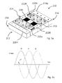
- FIG. 2 shows the superconductor switching arrangement 210 according to the present invention.
- the superconductor switching arrangement 210 includes a body 212 of superconducting material, a plurality of first connection zones 214 R, Y, B and a plurality of second connection zones 216.
- the superconductor body 212 is a monolith of homogenous superconductor material in the form of a rectangular plate.
- the superconductor body 212 of the embodiment is made by a known process of filling a mould with a constituent powder and sintering it.
- the powder In the case of YBCO, the powder would be a mixture of carbonates of yttrium, copper and barium well mixed and in stochiometric ratios. During sintering the heat applied to carbonates will convert the carbonates to oxides and form YBCO.
- a plate of magnesium diboride could be made in a similar way by sintering a well mixed powdered magnesium and boron in a stochiometric ratio.
- the properties of the superconductor body 212 are not restrictive and can be any known type which is suitable as per requirements of the described embodiments.
- the superconductor may be Bismuth Strontium Calcium Copper Oxide (BSCCO), Yttrium Barium Copper Oxide (YBCO) or Magnesium Diboride (MgB 2 ).
- BSCCO Bismuth Strontium Calcium Copper Oxide
- YBCO Yttrium Barium Copper Oxide
- MgB 2 Magnesium Diboride
- these materials need to be provided with the environment to achieve a superconducting state.
- the device may be placed within a cryostat with adequate cooling and thermal insulation etc. The cryostat and thermal insulation is not shown for the sake of clarity. Further, some applications will require the superconducting switching arrangement to be electrically, magnetically and thermally shielded.
- the plurality of first connection zones 214 includes three separate connection points R, Y, B provided in a linear arrangement across a shorter mid-line of the superconducting body 212.
- the first connection zones 214 extends across the entirety of the superconducting body 212 with a connection zone R, B provided at corresponding positions on opposing sides thereof.
- Each of the connection zones R, Y, B is separated from the adjacent zone via a dielectric barrier in the form of a block of electrical insulation 218 which abuts the connection zones R, Y, B on either side.
- the electrical insulation 218 may be any known type which could be incorporated into the superconducting body 212.
- a suitable insulator is aluminium oxide which has both good thermal and good electrical properties.
- Dielectric barriers may be formed by providing apertures in the superconducting plate and inserting alumina.
- the alumina may be introduced as a solid or a powder at the start of the sintering process which is used to form the superconductor body 212 described above.
- the alumina in solid or powdered form would be inserted into the required positions in the powder prior to sintering. It will be appreciated that, in the case of inserting solid blocks of alumina, the sintering process would take place at a temperature below the melting point of alumina.
- the apertures are vacant and a fluid such as air, gas or an insulating cryogen such as liquid nitrogen is used to occupy and insulate the apertures.
- connection zones 216 which are provided on the opposing end portions of the superconducting body 212 and which run parallel to the first connection zones 214.
- the switch arrangement 210 is shown in an operational state and as such each of the plurality of first connection zones 214 is connected to a single phase R, Y, B (namely one of red, yellow, blue) of a three-phase circuit and each of the second connections zones 216 is connected to a respective rail of a direct current, D.C., circuit.
- the electrical connection to the superconductor body 212 can be made in any suitable way.
- the connections zones 214, 216 may represent terminals which receive conductors or some other electrical junction.
- the electrical circuits referred to can be loads or sources of electrical power.
- the three phase electrical circuit is a supply which is converted to DC using the superconductor switching arrangement 210.
- a magnetic field 220 is provided perpendicular to the plane the rectangular superconductor body 212 (as indicated by arrows 220a and 220b) by a quenching device (as shown in Figures 6a and 6b and described later) which is operable to create a magnetic field of sufficient strength and distribution to selectively quench portions of the superconductor body 212.
- a quenching device as shown in Figures 6a and 6b and described later
- Figure 2a shows superconducting paths 222R, 222B formed between the red phase R and positive DC rail 216p and the blue phase B and the negative DC rail 216n.
- This configuration corresponds to a voltage waveform shown in Figure 2b be at time t 1 .
- a load (not shown) is connected across the DC rails at time t 1 , current flows from the red phase connection 214R, down superconducting path 222R to the positive DC rail 216p, through the load and returns to the electrical supply via the negative D.C. rail 216n which is connected and blue phase 214B via superconductor path 222B.
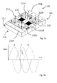
- Figures 3a and 3b shows the same superconductor switch arrangement 310 as depicted in Figure 2 and voltage waveform, but at time t 2 .
- the red R and yellow Y phases are equal and positive with respect to the blue phase B which is negative.
- the quenching device is configured to provide a superconductive path 222RY which connects both the red and yellow phase to the positive DC rail.
- t 3 as time progresses to t 3 (as shown in Figures 4a and 4b ), the red phase becomes negative and so the superconducting path extends between the yellow phase Y and positive DC rail 216p whilst the connection between the blue phase and the negative DC rail 216n is retained.
- the switching cycle between phases R, Y, B continues as time progresses until each phase is connected in turn to the positive DC rail 216p and negative DC rail 216n in accordance with the relative polarity with each rail 216.
- the switching between phases includes a sliding superconductive path 222 which traverses between each of the connection zones R, Y, B and which simultaneously connects adjacent phases to the DC rail 216 as it switches between phases.
- This configuration leads to short circuit between the phases R and Y in the region indicated by the dashed line 224 in Figure 3a .
- This sliding or diverting arrangement provides a more efficient switching from one phase to the other and largely prevents power dissipation when each section changes from a superconducting state to a resistive state.
- a further advantage of the sliding superconducting portions is that the reduction in resistive power reduces the time taken to re-establish superconductivity following a quench which raises the switching speed because the superconductor 212 does not require as much time to cool below its critical temperature.
- the sliding superconductive path 222 is advantageous, careful switching is required to prevent a prolonged short circuit and large currents between the adjacent phases which would increase as the potential difference between phases increases with time t.
- the first is to not switch off the applied magnetic field in that region but leave a partial applied field will in response to a predetermined short circuit current due to a voltage difference between the red and yellow phases.
- the second option is to make the shorted zone 224 from a superconductor of lower critical current density than the adjacent superconducting material.
- the third option is to operate the shorted zone at a higher temperature so that the short circuit results in a quench.
- the fourth option is to make the shorted zone from a thinner section of superconductor, thereby making the critical current density more easily exceeded. In essence, the above options all rely on making changes to a shorting zone so as to make the area quench under a particular current density which would flow between the phases.
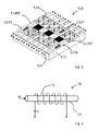
- Figure 5 shows a switching arrangement similar to the one described in Figures 2 to 4 , but which has been modified to enhance the sliding superconducting path which is necessary to prevent the rapid quenching of discrete regions of superconductor and the associated power dissipation this would cause.
- connection zone 514BT is included adjacent to the red phase.
- This connection zone 514BT is a supplementary connection for the blue phase B.
- the connection of the blue phase is always between the two blue phase connection zones 514B, 514BT. This allows superconducting paths 522B to be formed between blue and red phases, and yellow and blue phases.
- An additional electrical heating element 524 is also included on the surface of the superconductor body 512. Energising the electrical heating element 524 with a current from an electric source can assist quenching of the superconductive body 512 so as to divert the superconducting path.
- the wire can be made from any suitable resistive wire, for example, Nickel Chromium wire, which is insulated from the superconducting body 512 using a layer of sputtered Alumina.
- the wire may be fabricated in any suitable way, for example, by using an additive technique such as direct laser sintering, or an adhesive tape. It will be appreciated that the inclusion of the heating element is optional and some embodiments may not include this feature.
- FIGs 6a and 6b shows a switching arrangement 610 with a preferred embodiment of a quenching device 611 which is used to selectively provide the magnetic field (220a,b; Figures 2 to 4 ) to the superconducting switch arrangement shown in Figures 2 to 4 .
- a quenching device 611 which is used to selectively provide the magnetic field (220a,b; Figures 2 to 4 ) to the superconducting switch arrangement shown in Figures 2 to 4 .
- the second quenching device which is not shown is arranged in a similar fashion to the one described below, but over the positive rail half of the device to control the superconductive paths which connect the phases and positive D.C. rail 616p.
- the quenching device 611 is in the form of a closed magnetic circuit 624 which surrounds the superconducting body 612.
- the magnetic circuit 624 is rectangular in cross section and comprises two magnetic flux sources in the form of magnetically polarised members 626a, 626b arranged in parallel, one along each of the short sides of the magnetic circuit 624, either side of the superconducting body 612.
- the polarised members 626a,b are connected at each end with two corresponding parallel high permeability members 628a,b which extend between and connect to the corresponding pole North and South poles of the magnetically polarised members, along the long sides of the rectangular magnetic circuit 624.
- the arrangement of the magnetic circuit 624 is such that a magnetic field is presented perpendicular to the superconducting body 612 and the currents which flow in the superconducting paths 622B, 622Y.
- the magnetically polarised members 626a,b may be permanently magnetised, electromagnets or superconductors which are magnetised using known methods of flux pumping techniques.
- the quenching device 611 includes a plurality of coils 630 (of which only two are shown) are arranged in series between the magnetic flux sources on the proximal faces of the connecting members.
- the coils 630 are spaced and sized such that, when selectively energised, they can produce a magnetic field which opposes the magnetic field of the magnetic flux sources, thereby altering the magnetic field 620a which is presented to the surface of the superconducting body 612. In this way, the magnetic field 620a seen by the superconducting body 612, and hence the quenching, can be controlled to specific areas.
- a portion of superconducting material which forms a superconducting path 622B can be set up to allow the conduction pattern as described above. Altering the energised configuration of the coils 630 allows the superconducting path 622B to be swept across the superconducting body 612.
- the coils are placed within the high permeability members.
- the coils are placed in slots according to known techniques of manufacturing electrical windings.
- the described device can be used as a rectifier in which the first connections zones are connected to an alternating current supplied and the second connection zones are connected to a direct current load.
- the device can also be used to convert DC to AC simply by reversing the connections of the supply and load in the process described above.
- switching arrangements described above can be connected to another similar switching arrangement in a back to back configuration in which the second connection zones are connected together to provide a DC link.
- a power converter or inverter which comprises two of the superconducting switching arrangements which converts an input having a first AC frequency to an output having a second AC frequency.
- the invention can also be applied to any number of phases.
- the input has a first number of phases and the output has a second number of phases.
- Figure 7 shows an alternative embodiment of the switching arrangement 710 in which the superconducting body 712 is cylindrical.
- a hollow cylindrical superconducting body 712 having a first end 732 and a second end 734.
- the first end 732 includes a plurality of first connections zones 714 which are electrically coupled to a three-phase electrical supply and electrically isolated from one another with electrical insulation 718 in the form of alumina.
- the second end 734 of the superconducting body 712 includes the second connection zone 716 in the form of a positive DC connection.
- a quenching device 711 provides a perpendicular, in this case radial, magnetic field 720 to quench regions 721 of superconductor and define superconducting paths 722R, R'.
- the superconducting paths 722 R, R' link the RYB phases and the DC connection using a sliding superconducting path as described for the embodiments of Figures 2 to 4 .
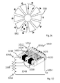
- the switching arrangement 710 is such that each phase is connected to a pair of connection zones such that a rotating magnetic dipole (described in more detail below with reference to Figures 8a and b ) can be used for the quenching device.
- each of the phases has two superconducting paths 722R, R' connecting to the positive DC rail.
- Figures 8a and 8b show radial and axial cross-sectional views of the cylindrical switching arrangement 710.
- a cylindrical inner magnetic core 738 having a longitudinal axis
- a first coil 740 (not shown in Figure 8b for the sake of clarity)
- the cylindrical superconducting body 721 which is coaxial with the inner magnetic core 738
- a second coil 742 and an outer magnetic core 744.
- the inner magnetic core 738, and first 740 and second 742 coils, and outer magnetic core 744 provide the quenching device.
- the coils 740, 742 can be energised to provide a magnetic dipole having flux lines which extend radially through the superconducting body where required to provide the quenched regions 721 and superconducting paths 722.
- the coils 740, 742 can be any suitable configuration which will allow the set up of the radial magnetic field 720.
- having a polyphase winding which can provide a rotating magnetic field allows the superconducting path to be rotated about the superconducting body such that the switching function as described above for the embodiments shown in Figures 2 to 4 can be provided simply by rotating the field circumferentially around the body.
- the cylindrical switching device provides rectification only with respect to one DC connection.
- two of the cylindrical switching arrangements are needed to provide a full rectifier.
- An additional electrical heating element 724 may also be included within the superconductor body 712. Energising the electrical heating element 724 with a current from an electric source can assist quenching of the superconductive body 712 so as to divert the superconducting path.
- the heating element can be made from any suitable resistive wire, for example, nickel- chromium wire, which is insulated from the superconducting body 712 using a suitable dielectric, for example, a poly vinyl chlorine coating.
- the wire may be buried within the superconducting body prior to the sintering process used to fabricate the body (in which case the insulation would have to withstand the associated pressure), or alternatively passageways may be bored through the superconducting body and the resistive wire subsequently fed through and connected to an electrical supply.
- a surface mounted resistive wire may also be used to provide the heating elements as described in the other embodiments.
- the superconducting body 912 is in the form of a monolithic homogeneous disc, as shown in Figures 9a, 9b and 9c .
- the first connection zones 914 are provided on the periphery of the disc 912 and the DC connection is provided at the second connection zone 916 at the central region of the disc.
- the quenching device 938 includes a plurality of coils 940 as illustrated in Figure 9c which provide the superconducting body 912 with a perpendicular magnetic field 920, axial in this case, to provide the quenched regions 921 and superconducting paths 922. These regions 921 and paths 922 can be circumferentially moved around the disc by selectively energising the coils 940 so as to connect each of the first connection zones 914 to the second connection zone 916 in turn.
- the quenching device 938 and coils 940 can be made in accordance with a known design of winding termed a "disc" or "pancake” winding. As with the cylindrical embodiment, it will be appreciated that two such devices are required to provide a rectifier. Nevertheless, the switching arrangement 910 may be employed in other applications without a second device where suitable.
- the two halves of the quenching device 938 are held together by clamps, struts or spacers (not shown).
- the clamps, struts or spacers I on either side of the superconducting body may be made of laminated material of high magnetic permeability in order to provide a more efficient magnetic circuit.
- An additional electrical heating element 922 may also be included on the surface of the superconductor body 912. Energising the electrical heating element 924 with a current from an electric source can assist quenching of the superconductive body 912 so as to divert the superconducting path.
- the wire can be made from any suitable resistive wire, for example, nickel- chromium wire, which is insulated from the superconducting body 912 using a layer of sputtered Alumina.
- the wire may be fabricated in any suitable way, for example, by using an additive technique such as direct laser sintering, or an adhesive tape. It will be appreciated that the inclusion of the heating element is optional and some embodiments may not include this feature. Further, the pattern of the conductor may be altered to suit the quenching pattern required.
- the superconducting switching arrangement 1010 is used to provide a tapped transformer, as shown in Figure 10 .
- the transformer has a superconductor body 1012 in the form of a rectangular plate-like monolith of homogenous superconductor material, a plurality of first connection zones 1014 R, Y, B and a second connection zone 1016.
- the properties of the superconductor 1012 are not restrictive and can be any known type which is suitable as per requirements of the described embodiments.
- the superconductor may be bismuth strontium calcium copper oxide (BSCCO), yttrium barium copper oxide (YBCO) or magnesium diboride (MgB 2 ).
- BSCCO bismuth strontium calcium copper oxide
- YBCO yttrium barium copper oxide
- MgB 2 magnesium diboride
- these materials need to be provided with the environment to achieve a superconducting state.
- the device may be placed within a cryostat with adequate cooling and thermal insulation etc. The cryostat and thermal insulation is not shown for the sake of clarity. Further, some applications will require the superconducting switching arrangement to be electrically, magnetically and thermally shielded.
- the plurality of first connection zones 1014 includes three separate connection points provided in a linear arrangement along one edge of the superconducting body 1012.
- the first connection zones 1014 extend across the entirety of the superconducting body 1012 with a connection zone provided at corresponding positions on opposing corners of the edge.
- Each of the first connection zones is separated from the adjacent zone via a dielectric barrier in the form of a block of electrical insulation 1018 which abuts the connection zones on either side.
- the electrical insulation 1018 may be any known type which could be incorporated into the superconducting body 1012.
- the first connection zones 1014[1], 1014[2], 1014[3] are connected to different points along the length of a transformer winding 1048.
- the winding 1048 can be considered to be the secondary winding.
- the [1]first connection zone 1014 is connected at a first end 1050 of the winding 1048, the [2] first connection zone 1014 is connected approximately a third of the way along the winding and the [3] first connection zone 1014 is connected approximately half way along the winding 1048.
- the second end 1052 of the secondary winding 1048 is connected to an electrical network or load (not shown) as indicated by arrow 1054.
- the other electrical network or load connection is made through the second connection zone 1016.
- the other winding of the transformer 1010, the primary winding 1056, is connected to an electrical source (not shown).
- a magnetic field 1020 is provided perpendicular to the plane the rectangular superconductor body 1012 by a quenching device (not shown but as described with reference to Figures 5a and 5b above) which is operable to create a magnetic field 1020 of sufficient strength and distribution to selectively quench regions 1021 of the superconductor body 1012. Hence, in this way, portions of the superconductor body 1012 can be quenched and returned to a high resistive state, thereby removing the superconducting path 1022. Thus, it is possible to isolate between the different connection zones as per a required configuration.
- An additional electrical heating element 1024 is also included on the surface of the superconductor body 1012. Energising the electrical heating element 1024 with a current from an electric source can assist quenching of the superconductive body 1012 so as to divert the superconducting path.
- the wire can be made from any suitable resistive wire, for example, nickel-chromium wire, which is insulated from the superconducting body 1012 using a layer of sputtered alumina.
- the wire may be fabricated in any suitable way, for example, by using an additive technique such as direct laser sintering, or an adhesive tape. It will be appreciated that the inclusion of the heating element is optional and some embodiments may not include this feature.
- the switch arrangement 1010 is shown in an operational state with a superconductive path 1022 being provided from the first connection zone 1014[1] to the second connection zone 1016.
- the transformer ratio between the primary 1056 and secondary 1048 windings is 4:6 (as shown in Figure 10 ) and so represents a step up transformer.
- Providing the superconducting path 1022 between the first connection zone 1014[2] and the second connection results in a 1:1 transformer, and for having the superconducting path 1022 between the first connection zone 1014[3] and the second connection results in a 4:3 step down transformer.
- the ratio of the windings can be adjusted as required.
- the ratio of the windings can be chosen as required for a particular application and the load and source may be interchanged.
- a changeover switch in which a single input is switched between a choice of outputs. This would operate in a similar way to the tapped transformer, except that the switching arrangement would be line connected with each of the first connection zones being connected to a load, and the second connection zone being connected to a supply terminal of an electrical source. In this way, switching the superconductive path between first connection zones would switch the electrical circuit between one load and another.
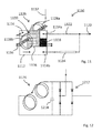
- FIG 11 shows yet another embodiment where there is provided a switching arrangement 1110 in the form of a fault current limiter in which a single input is switched between a choice of outputs so as to limit current in an external circuit (not shown).
- the switching arrangement 1110 includes a superconducting body 1112 in the form of a rectangular plate-like monolith of homogenous superconductor material having first connection zones 1114 and a second connection zone 1116.
- the second connection zone 1116 is connected to an electrical source (via a quenching device, as described below).
- the two first connection zones 1114a, 1114b are arranged along one side of the superconducting body 1112 and are separated by an electrical insulator 1118.
- the quenching device 1126 is in the form of a solenoid 1128 which has two serially connected coils 1128a, 1128b arranged coaxially either side of the superconducting body 1112 so as to create a quenched zone 1130 between the first connection zones 1114a, 1114b and the low impedance line output 1122, when energised.
- One end of the solenoid 1128 is connected to an electrical source 1132 (not shown) with the other connected to the second connection zone 1116.
- An additional electrical heating element 1136 is also included on the surface of the superconductor body 1112. Energising the electrical heating element 1136 with a current from an electric source can assist quenching of the superconductive body 1112 so as to divert the superconducting path.
- the wire can be made from any suitable resistive wire, for example, nickel-chromium wire, which is insulated from the superconducting body 1112 using a layer of sputtered alumina.
- the wire may be fabricated in any suitable way, for example, by using an additive technique such as direct laser sintering, or an adhesive tape. It will be appreciated that the inclusion of the heating element is optional and some embodiments may not include this feature.
- the solenoid is connected to an electrical supply such that a current below a predetermined level (the rated current) flows through the first and second coils to the second connection zone, through a superconducting path between the second and first connection zones, and to the load via the low impedance path.
- the rated current of the device is that which creates a magnetic field which is small enough not to quench the superconducting path.
- FIG. 12 there is shown an embodiment of the quenching device 1126 shown in Figure 11 which includes a full wave diode rectifier 1212 and filter in the form of a capacitor 1214 which are connected to the solenoid so as to rectify the AC supply for the solenoid.
- the current in the solenoid can be controlled by an electrical protection circuit that detects when an electrical limit is exceeded and passes current through the solenoid.
- the solenoid may be located outside the cryostat that contains the superconducting body 1112 to help retain the thermal integrity of the cryostat, thereby increasing the efficiency of the arrangement.
- the rectifier and the filtering circuit may also be outside the cryostat.
- the superconducting body may include passageways in which heat transfer fluid can flow.
- the passageways may include valves or switches to redirect a flow of fluid, thereby allowing the portions of the superconducting body to heat up and quench or to cool down and restore superconductivity, depending on the temperature of the heat transfer fluid and its pattern of flow.
Landscapes
- Containers, Films, And Cooling For Superconductive Devices (AREA)
- Manufacturing Of Electrical Connectors (AREA)
Applications Claiming Priority (1)
| Application Number | Priority Date | Filing Date | Title |
|---|---|---|---|
| GB201117689A GB201117689D0 (en) | 2011-10-13 | 2011-10-13 | A superconductor switching arrangement |
Publications (3)
| Publication Number | Publication Date |
|---|---|
| EP2581956A2 true EP2581956A2 (de) | 2013-04-17 |
| EP2581956A3 EP2581956A3 (de) | 2014-09-03 |
| EP2581956B1 EP2581956B1 (de) | 2016-04-13 |
Family
ID=45091991
Family Applications (1)
| Application Number | Title | Priority Date | Filing Date |
|---|---|---|---|
| EP12185884.9A Not-in-force EP2581956B1 (de) | 2011-10-13 | 2012-09-25 | Schaltanordnung für Supraleiter |
Country Status (3)
| Country | Link |
|---|---|
| US (1) | US8718732B2 (de) |
| EP (1) | EP2581956B1 (de) |
| GB (1) | GB201117689D0 (de) |
Cited By (2)
| Publication number | Priority date | Publication date | Assignee | Title |
|---|---|---|---|---|
| GB2566579A (en) * | 2017-06-30 | 2019-03-20 | Boeing Co | System and method for operating a bulk superconductor device |
| US11070123B2 (en) | 2017-07-07 | 2021-07-20 | The Boeing Compan | Energy storage and energy storage device |
Families Citing this family (4)
| Publication number | Priority date | Publication date | Assignee | Title |
|---|---|---|---|---|
| DE102014217250A1 (de) * | 2014-08-29 | 2016-03-03 | Siemens Aktiengesellschaft | Supraleitende Spuleneinrichtung mit schaltbarem Leiterabschnitt sowie Verfahren zum Umschalten |
| EP4035214A4 (de) * | 2019-10-25 | 2023-10-18 | Victoria Link Limited | Supraleitender schalter |
| EP4272267A4 (de) * | 2021-01-26 | 2025-05-07 | Victoria Link Limited | Verbesserungen an supraleitenden schaltern |
| JP2025531051A (ja) * | 2022-08-31 | 2025-09-19 | ヴィクトリア リンク リミテッド | 機械的に切り替え可能な超伝導フラックスポンプ |
Family Cites Families (6)
| Publication number | Priority date | Publication date | Assignee | Title |
|---|---|---|---|---|
| JPH03123111A (ja) | 1989-10-06 | 1991-05-24 | Nippon Telegr & Teleph Corp <Ntt> | 位相器 |
| JP2002136144A (ja) * | 2000-10-26 | 2002-05-10 | Internatl Superconductivity Technology Center | 超電導電源回路 |
| US20090322332A1 (en) | 2007-03-28 | 2009-12-31 | Varian, Inc. | NMR probe superconductive transmit/receive switches |
| GB0806090D0 (en) * | 2008-04-04 | 2008-05-14 | Rolls Royce Plc | A superconducting fault current limiter |
| WO2009157532A1 (ja) | 2008-06-26 | 2009-12-30 | 国立大学法人京都大学 | 超電導電力変換器 |
| US8299732B2 (en) * | 2009-01-15 | 2012-10-30 | Rockwell Automation Technologies, Inc. | Power conversion system and method |
-
2011
- 2011-10-13 GB GB201117689A patent/GB201117689D0/en not_active Ceased
-
2012
- 2012-09-14 US US13/618,792 patent/US8718732B2/en active Active
- 2012-09-25 EP EP12185884.9A patent/EP2581956B1/de not_active Not-in-force
Non-Patent Citations (1)
| Title |
|---|
| None |
Cited By (4)
| Publication number | Priority date | Publication date | Assignee | Title |
|---|---|---|---|---|
| GB2566579A (en) * | 2017-06-30 | 2019-03-20 | Boeing Co | System and method for operating a bulk superconductor device |
| GB2566579B (en) * | 2017-06-30 | 2020-12-30 | Boeing Co | System and method for operating a bulk superconductor device |
| US10971291B2 (en) | 2017-06-30 | 2021-04-06 | The Boeing Company | System and method for operating a bulk superconductor device |
| US11070123B2 (en) | 2017-07-07 | 2021-07-20 | The Boeing Compan | Energy storage and energy storage device |
Also Published As
| Publication number | Publication date |
|---|---|
| US8718732B2 (en) | 2014-05-06 |
| EP2581956A3 (de) | 2014-09-03 |
| EP2581956B1 (de) | 2016-04-13 |
| GB201117689D0 (en) | 2011-11-23 |
| US20130096008A1 (en) | 2013-04-18 |
Similar Documents
| Publication | Publication Date | Title |
|---|---|---|
| EP2581956B1 (de) | Schaltanordnung für Supraleiter | |
| US20020018327A1 (en) | Multi-winding fault-current limiter coil with flux shaper and cooling for use in an electrical power transmission/distribution application | |
| US8107211B2 (en) | High temperature superconducting electromechanical system with frequency controlled commutation for rotor excitation | |
| CA2403861A1 (en) | A superconducting transformer | |
| Qiu et al. | Winding design and electromagnetic analysis for a 1250-kVA HTS transformer | |
| Aly et al. | Comparison between resistive and inductive superconducting fault current limiters for fault current limiting | |
| KR102033032B1 (ko) | 초전도성 직류 케이블 시스템을 구비한 배열 | |
| JP3892605B2 (ja) | 限流素子用超電導コイル装置 | |
| KR100717351B1 (ko) | 동시퀀치를 위한 초전도 바이패스 리액터를 갖는 한류기 | |
| US20240313775A1 (en) | High-temperature superconducting switches and rectifiers | |
| EP1305871B1 (de) | Schutz für die feldwicklung einer supraleitenden synchronmaschine | |
| EP0395940A2 (de) | Quenchausbreitungseinrichtung für einen supraleitenden Magneten | |
| ten Kate et al. | High current and high power superconducting rectifiers | |
| KR20170012101A (ko) | 전력 공급 서비스 네트워크에 통합될 수 있는 전류 제한 장치 | |
| US3394335A (en) | Thin wire power cryotrons | |
| US11587701B2 (en) | Series-connected superconducting magnet cables | |
| US20250292938A1 (en) | Rapid dump of superconductor magnets | |
| Sim et al. | Equal current distribution in parallel circuits of resistive superconducting fault current limiters using multiple superconducting inter-phase transformers | |
| JP2002262450A (ja) | 超伝導薄膜を用いた変圧器型限流方法及び限流器 | |
| WO2021195364A1 (en) | Emergency shutdown of a no-insulation magnet | |
| Neumueller et al. | Economically viable fault current limiters using YBCO coated conductors | |
| RU159361U1 (ru) | Сверхпроводниковый ограничитель переменного тока индуктивного типа с насыщенным магнитопроводом | |
| AU2023286679A1 (en) | Superconducting power devices | |
| CN118888246A (zh) | 一种基于全波变压器整流器的超导磁体励磁装置 | |
| Liu et al. | Quenching Characteristics of Different Types of Superconducting Fault Current Limiting Modules |
Legal Events
| Date | Code | Title | Description |
|---|---|---|---|
| PUAI | Public reference made under article 153(3) epc to a published international application that has entered the european phase |
Free format text: ORIGINAL CODE: 0009012 |
|
| AK | Designated contracting states |
Kind code of ref document: A2 Designated state(s): AL AT BE BG CH CY CZ DE DK EE ES FI FR GB GR HR HU IE IS IT LI LT LU LV MC MK MT NL NO PL PT RO RS SE SI SK SM TR |
|
| AX | Request for extension of the european patent |
Extension state: BA ME |
|
| PUAL | Search report despatched |
Free format text: ORIGINAL CODE: 0009013 |
|
| AK | Designated contracting states |
Kind code of ref document: A3 Designated state(s): AL AT BE BG CH CY CZ DE DK EE ES FI FR GB GR HR HU IE IS IT LI LT LU LV MC MK MT NL NO PL PT RO RS SE SI SK SM TR |
|
| AX | Request for extension of the european patent |
Extension state: BA ME |
|
| RIC1 | Information provided on ipc code assigned before grant |
Ipc: H01L 39/20 20060101AFI20140731BHEP Ipc: H03K 17/92 20060101ALI20140731BHEP |
|
| 17P | Request for examination filed |
Effective date: 20150303 |
|
| RBV | Designated contracting states (corrected) |
Designated state(s): AL AT BE BG CH CY CZ DE DK EE ES FI FR GB GR HR HU IE IS IT LI LT LU LV MC MK MT NL NO PL PT RO RS SE SI SK SM TR |
|
| RAP1 | Party data changed (applicant data changed or rights of an application transferred) |
Owner name: ROLLS-ROYCE PLC |
|
| GRAP | Despatch of communication of intention to grant a patent |
Free format text: ORIGINAL CODE: EPIDOSNIGR1 |
|
| INTG | Intention to grant announced |
Effective date: 20150807 |
|
| GRAS | Grant fee paid |
Free format text: ORIGINAL CODE: EPIDOSNIGR3 |
|
| INTG | Intention to grant announced |
Effective date: 20160126 |
|
| GRAA | (expected) grant |
Free format text: ORIGINAL CODE: 0009210 |
|
| AK | Designated contracting states |
Kind code of ref document: B1 Designated state(s): AL AT BE BG CH CY CZ DE DK EE ES FI FR GB GR HR HU IE IS IT LI LT LU LV MC MK MT NL NO PL PT RO RS SE SI SK SM TR |
|
| REG | Reference to a national code |
Ref country code: GB Ref legal event code: FG4D |
|
| REG | Reference to a national code |
Ref country code: AT Ref legal event code: REF Ref document number: 790979 Country of ref document: AT Kind code of ref document: T Effective date: 20160415 Ref country code: CH Ref legal event code: EP |
|
| REG | Reference to a national code |
Ref country code: IE Ref legal event code: FG4D |
|
| REG | Reference to a national code |
Ref country code: DE Ref legal event code: R096 Ref document number: 602012016986 Country of ref document: DE |
|
| REG | Reference to a national code |
Ref country code: LT Ref legal event code: MG4D |
|
| REG | Reference to a national code |
Ref country code: AT Ref legal event code: MK05 Ref document number: 790979 Country of ref document: AT Kind code of ref document: T Effective date: 20160413 |
|
| REG | Reference to a national code |
Ref country code: NL Ref legal event code: MP Effective date: 20160413 |
|
| REG | Reference to a national code |
Ref country code: FR Ref legal event code: PLFP Year of fee payment: 5 |
|
| PG25 | Lapsed in a contracting state [announced via postgrant information from national office to epo] |
Ref country code: NL Free format text: LAPSE BECAUSE OF FAILURE TO SUBMIT A TRANSLATION OF THE DESCRIPTION OR TO PAY THE FEE WITHIN THE PRESCRIBED TIME-LIMIT Effective date: 20160413 Ref country code: PL Free format text: LAPSE BECAUSE OF FAILURE TO SUBMIT A TRANSLATION OF THE DESCRIPTION OR TO PAY THE FEE WITHIN THE PRESCRIBED TIME-LIMIT Effective date: 20160413 Ref country code: NO Free format text: LAPSE BECAUSE OF FAILURE TO SUBMIT A TRANSLATION OF THE DESCRIPTION OR TO PAY THE FEE WITHIN THE PRESCRIBED TIME-LIMIT Effective date: 20160713 Ref country code: LT Free format text: LAPSE BECAUSE OF FAILURE TO SUBMIT A TRANSLATION OF THE DESCRIPTION OR TO PAY THE FEE WITHIN THE PRESCRIBED TIME-LIMIT Effective date: 20160413 Ref country code: FI Free format text: LAPSE BECAUSE OF FAILURE TO SUBMIT A TRANSLATION OF THE DESCRIPTION OR TO PAY THE FEE WITHIN THE PRESCRIBED TIME-LIMIT Effective date: 20160413 |
|
| PG25 | Lapsed in a contracting state [announced via postgrant information from national office to epo] |
Ref country code: AT Free format text: LAPSE BECAUSE OF FAILURE TO SUBMIT A TRANSLATION OF THE DESCRIPTION OR TO PAY THE FEE WITHIN THE PRESCRIBED TIME-LIMIT Effective date: 20160413 Ref country code: LV Free format text: LAPSE BECAUSE OF FAILURE TO SUBMIT A TRANSLATION OF THE DESCRIPTION OR TO PAY THE FEE WITHIN THE PRESCRIBED TIME-LIMIT Effective date: 20160413 Ref country code: RS Free format text: LAPSE BECAUSE OF FAILURE TO SUBMIT A TRANSLATION OF THE DESCRIPTION OR TO PAY THE FEE WITHIN THE PRESCRIBED TIME-LIMIT Effective date: 20160413 Ref country code: SE Free format text: LAPSE BECAUSE OF FAILURE TO SUBMIT A TRANSLATION OF THE DESCRIPTION OR TO PAY THE FEE WITHIN THE PRESCRIBED TIME-LIMIT Effective date: 20160413 Ref country code: PT Free format text: LAPSE BECAUSE OF FAILURE TO SUBMIT A TRANSLATION OF THE DESCRIPTION OR TO PAY THE FEE WITHIN THE PRESCRIBED TIME-LIMIT Effective date: 20160816 Ref country code: HR Free format text: LAPSE BECAUSE OF FAILURE TO SUBMIT A TRANSLATION OF THE DESCRIPTION OR TO PAY THE FEE WITHIN THE PRESCRIBED TIME-LIMIT Effective date: 20160413 Ref country code: ES Free format text: LAPSE BECAUSE OF FAILURE TO SUBMIT A TRANSLATION OF THE DESCRIPTION OR TO PAY THE FEE WITHIN THE PRESCRIBED TIME-LIMIT Effective date: 20160413 Ref country code: GR Free format text: LAPSE BECAUSE OF FAILURE TO SUBMIT A TRANSLATION OF THE DESCRIPTION OR TO PAY THE FEE WITHIN THE PRESCRIBED TIME-LIMIT Effective date: 20160714 |
|
| PG25 | Lapsed in a contracting state [announced via postgrant information from national office to epo] |
Ref country code: IT Free format text: LAPSE BECAUSE OF FAILURE TO SUBMIT A TRANSLATION OF THE DESCRIPTION OR TO PAY THE FEE WITHIN THE PRESCRIBED TIME-LIMIT Effective date: 20160413 Ref country code: BE Free format text: LAPSE BECAUSE OF FAILURE TO SUBMIT A TRANSLATION OF THE DESCRIPTION OR TO PAY THE FEE WITHIN THE PRESCRIBED TIME-LIMIT Effective date: 20160413 |
|
| REG | Reference to a national code |
Ref country code: DE Ref legal event code: R097 Ref document number: 602012016986 Country of ref document: DE |
|
| PG25 | Lapsed in a contracting state [announced via postgrant information from national office to epo] |
Ref country code: CZ Free format text: LAPSE BECAUSE OF FAILURE TO SUBMIT A TRANSLATION OF THE DESCRIPTION OR TO PAY THE FEE WITHIN THE PRESCRIBED TIME-LIMIT Effective date: 20160413 Ref country code: SK Free format text: LAPSE BECAUSE OF FAILURE TO SUBMIT A TRANSLATION OF THE DESCRIPTION OR TO PAY THE FEE WITHIN THE PRESCRIBED TIME-LIMIT Effective date: 20160413 Ref country code: RO Free format text: LAPSE BECAUSE OF FAILURE TO SUBMIT A TRANSLATION OF THE DESCRIPTION OR TO PAY THE FEE WITHIN THE PRESCRIBED TIME-LIMIT Effective date: 20160413 Ref country code: EE Free format text: LAPSE BECAUSE OF FAILURE TO SUBMIT A TRANSLATION OF THE DESCRIPTION OR TO PAY THE FEE WITHIN THE PRESCRIBED TIME-LIMIT Effective date: 20160413 Ref country code: DK Free format text: LAPSE BECAUSE OF FAILURE TO SUBMIT A TRANSLATION OF THE DESCRIPTION OR TO PAY THE FEE WITHIN THE PRESCRIBED TIME-LIMIT Effective date: 20160413 |
|
| PLBE | No opposition filed within time limit |
Free format text: ORIGINAL CODE: 0009261 |
|
| STAA | Information on the status of an ep patent application or granted ep patent |
Free format text: STATUS: NO OPPOSITION FILED WITHIN TIME LIMIT |
|
| PG25 | Lapsed in a contracting state [announced via postgrant information from national office to epo] |
Ref country code: SM Free format text: LAPSE BECAUSE OF FAILURE TO SUBMIT A TRANSLATION OF THE DESCRIPTION OR TO PAY THE FEE WITHIN THE PRESCRIBED TIME-LIMIT Effective date: 20160413 |
|
| 26N | No opposition filed |
Effective date: 20170116 |
|
| PG25 | Lapsed in a contracting state [announced via postgrant information from national office to epo] |
Ref country code: MC Free format text: LAPSE BECAUSE OF FAILURE TO SUBMIT A TRANSLATION OF THE DESCRIPTION OR TO PAY THE FEE WITHIN THE PRESCRIBED TIME-LIMIT Effective date: 20160413 |
|
| REG | Reference to a national code |
Ref country code: CH Ref legal event code: PL |
|
| PG25 | Lapsed in a contracting state [announced via postgrant information from national office to epo] |
Ref country code: SI Free format text: LAPSE BECAUSE OF FAILURE TO SUBMIT A TRANSLATION OF THE DESCRIPTION OR TO PAY THE FEE WITHIN THE PRESCRIBED TIME-LIMIT Effective date: 20160413 |
|
| REG | Reference to a national code |
Ref country code: IE Ref legal event code: MM4A |
|
| PG25 | Lapsed in a contracting state [announced via postgrant information from national office to epo] |
Ref country code: LI Free format text: LAPSE BECAUSE OF NON-PAYMENT OF DUE FEES Effective date: 20160930 Ref country code: CH Free format text: LAPSE BECAUSE OF NON-PAYMENT OF DUE FEES Effective date: 20160930 Ref country code: IE Free format text: LAPSE BECAUSE OF NON-PAYMENT OF DUE FEES Effective date: 20160925 |
|
| PG25 | Lapsed in a contracting state [announced via postgrant information from national office to epo] |
Ref country code: LU Free format text: LAPSE BECAUSE OF NON-PAYMENT OF DUE FEES Effective date: 20160925 |
|
| REG | Reference to a national code |
Ref country code: FR Ref legal event code: PLFP Year of fee payment: 6 |
|
| PG25 | Lapsed in a contracting state [announced via postgrant information from national office to epo] |
Ref country code: HU Free format text: LAPSE BECAUSE OF FAILURE TO SUBMIT A TRANSLATION OF THE DESCRIPTION OR TO PAY THE FEE WITHIN THE PRESCRIBED TIME-LIMIT; INVALID AB INITIO Effective date: 20120925 Ref country code: CY Free format text: LAPSE BECAUSE OF FAILURE TO SUBMIT A TRANSLATION OF THE DESCRIPTION OR TO PAY THE FEE WITHIN THE PRESCRIBED TIME-LIMIT Effective date: 20160413 |
|
| PG25 | Lapsed in a contracting state [announced via postgrant information from national office to epo] |
Ref country code: MT Free format text: LAPSE BECAUSE OF NON-PAYMENT OF DUE FEES Effective date: 20160930 Ref country code: TR Free format text: LAPSE BECAUSE OF FAILURE TO SUBMIT A TRANSLATION OF THE DESCRIPTION OR TO PAY THE FEE WITHIN THE PRESCRIBED TIME-LIMIT Effective date: 20160413 Ref country code: MK Free format text: LAPSE BECAUSE OF FAILURE TO SUBMIT A TRANSLATION OF THE DESCRIPTION OR TO PAY THE FEE WITHIN THE PRESCRIBED TIME-LIMIT Effective date: 20160413 Ref country code: IS Free format text: LAPSE BECAUSE OF FAILURE TO SUBMIT A TRANSLATION OF THE DESCRIPTION OR TO PAY THE FEE WITHIN THE PRESCRIBED TIME-LIMIT Effective date: 20160413 |
|
| PG25 | Lapsed in a contracting state [announced via postgrant information from national office to epo] |
Ref country code: BG Free format text: LAPSE BECAUSE OF FAILURE TO SUBMIT A TRANSLATION OF THE DESCRIPTION OR TO PAY THE FEE WITHIN THE PRESCRIBED TIME-LIMIT Effective date: 20160413 |
|
| REG | Reference to a national code |
Ref country code: FR Ref legal event code: PLFP Year of fee payment: 7 |
|
| PG25 | Lapsed in a contracting state [announced via postgrant information from national office to epo] |
Ref country code: AL Free format text: LAPSE BECAUSE OF FAILURE TO SUBMIT A TRANSLATION OF THE DESCRIPTION OR TO PAY THE FEE WITHIN THE PRESCRIBED TIME-LIMIT Effective date: 20160413 |
|
| REG | Reference to a national code |
Ref country code: DE Ref legal event code: R079 Ref document number: 602012016986 Country of ref document: DE Free format text: PREVIOUS MAIN CLASS: H01L0039200000 Ipc: H10N0060355000 |
|
| P01 | Opt-out of the competence of the unified patent court (upc) registered |
Effective date: 20230528 |
|
| PGFP | Annual fee paid to national office [announced via postgrant information from national office to epo] |
Ref country code: GB Payment date: 20230926 Year of fee payment: 12 |
|
| PGFP | Annual fee paid to national office [announced via postgrant information from national office to epo] |
Ref country code: FR Payment date: 20230926 Year of fee payment: 12 Ref country code: DE Payment date: 20230928 Year of fee payment: 12 |
|
| REG | Reference to a national code |
Ref country code: DE Ref legal event code: R119 Ref document number: 602012016986 Country of ref document: DE |
|
| GBPC | Gb: european patent ceased through non-payment of renewal fee |
Effective date: 20240925 |
|
| PG25 | Lapsed in a contracting state [announced via postgrant information from national office to epo] |
Ref country code: DE Free format text: LAPSE BECAUSE OF NON-PAYMENT OF DUE FEES Effective date: 20250401 |
|
| PG25 | Lapsed in a contracting state [announced via postgrant information from national office to epo] |
Ref country code: GB Free format text: LAPSE BECAUSE OF NON-PAYMENT OF DUE FEES Effective date: 20240925 |
|
| PG25 | Lapsed in a contracting state [announced via postgrant information from national office to epo] |
Ref country code: FR Free format text: LAPSE BECAUSE OF NON-PAYMENT OF DUE FEES Effective date: 20240930 |