EP2581902A1 - Audio hybrid encoding device, and audio hybrid decoding device - Google Patents
Audio hybrid encoding device, and audio hybrid decoding device Download PDFInfo
- Publication number
- EP2581902A1 EP2581902A1 EP11795393.5A EP11795393A EP2581902A1 EP 2581902 A1 EP2581902 A1 EP 2581902A1 EP 11795393 A EP11795393 A EP 11795393A EP 2581902 A1 EP2581902 A1 EP 2581902A1
- Authority
- EP
- European Patent Office
- Prior art keywords
- signal
- frame
- transform
- coding mode
- inverse
- Prior art date
- Legal status (The legal status is an assumption and is not a legal conclusion. Google has not performed a legal analysis and makes no representation as to the accuracy of the status listed.)
- Withdrawn
Links
- 238000000034 method Methods 0.000 claims abstract description 76
- 230000007704 transition Effects 0.000 claims description 61
- 230000008569 process Effects 0.000 claims description 56
- 238000012545 processing Methods 0.000 claims description 34
- 230000005284 excitation Effects 0.000 claims description 18
- 230000005236 sound signal Effects 0.000 abstract description 7
- 238000005516 engineering process Methods 0.000 description 28
- 238000010586 diagram Methods 0.000 description 25
- 230000001052 transient effect Effects 0.000 description 23
- 230000000694 effects Effects 0.000 description 14
- 239000013598 vector Substances 0.000 description 9
- 230000002441 reversible effect Effects 0.000 description 8
- 238000004458 analytical method Methods 0.000 description 5
- 230000006866 deterioration Effects 0.000 description 3
- 238000009499 grossing Methods 0.000 description 3
- NRNCYVBFPDDJNE-UHFFFAOYSA-N pemoline Chemical compound O1C(N)=NC(=O)C1C1=CC=CC=C1 NRNCYVBFPDDJNE-UHFFFAOYSA-N 0.000 description 3
- 230000015572 biosynthetic process Effects 0.000 description 2
- 230000008859 change Effects 0.000 description 2
- 238000004891 communication Methods 0.000 description 2
- 230000006870 function Effects 0.000 description 2
- 230000004048 modification Effects 0.000 description 2
- 238000012986 modification Methods 0.000 description 2
- 238000013139 quantization Methods 0.000 description 2
- 230000003595 spectral effect Effects 0.000 description 2
- 238000003786 synthesis reaction Methods 0.000 description 2
- 230000008901 benefit Effects 0.000 description 1
- 238000006243 chemical reaction Methods 0.000 description 1
- 230000007774 longterm Effects 0.000 description 1
- 230000007246 mechanism Effects 0.000 description 1
- 238000007493 shaping process Methods 0.000 description 1
- 238000001308 synthesis method Methods 0.000 description 1
- 230000002123 temporal effect Effects 0.000 description 1
- 238000012800 visualization Methods 0.000 description 1
Images


Classifications
-
- G—PHYSICS
- G10—MUSICAL INSTRUMENTS; ACOUSTICS
- G10L—SPEECH ANALYSIS TECHNIQUES OR SPEECH SYNTHESIS; SPEECH RECOGNITION; SPEECH OR VOICE PROCESSING TECHNIQUES; SPEECH OR AUDIO CODING OR DECODING
- G10L19/00—Speech or audio signals analysis-synthesis techniques for redundancy reduction, e.g. in vocoders; Coding or decoding of speech or audio signals, using source filter models or psychoacoustic analysis
- G10L19/02—Speech or audio signals analysis-synthesis techniques for redundancy reduction, e.g. in vocoders; Coding or decoding of speech or audio signals, using source filter models or psychoacoustic analysis using spectral analysis, e.g. transform vocoders or subband vocoders
- G10L19/0212—Speech or audio signals analysis-synthesis techniques for redundancy reduction, e.g. in vocoders; Coding or decoding of speech or audio signals, using source filter models or psychoacoustic analysis using spectral analysis, e.g. transform vocoders or subband vocoders using orthogonal transformation
-
- G—PHYSICS
- G10—MUSICAL INSTRUMENTS; ACOUSTICS
- G10L—SPEECH ANALYSIS TECHNIQUES OR SPEECH SYNTHESIS; SPEECH RECOGNITION; SPEECH OR VOICE PROCESSING TECHNIQUES; SPEECH OR AUDIO CODING OR DECODING
- G10L19/00—Speech or audio signals analysis-synthesis techniques for redundancy reduction, e.g. in vocoders; Coding or decoding of speech or audio signals, using source filter models or psychoacoustic analysis
- G10L19/02—Speech or audio signals analysis-synthesis techniques for redundancy reduction, e.g. in vocoders; Coding or decoding of speech or audio signals, using source filter models or psychoacoustic analysis using spectral analysis, e.g. transform vocoders or subband vocoders
- G10L19/022—Blocking, i.e. grouping of samples in time; Choice of analysis windows; Overlap factoring
- G10L19/025—Detection of transients or attacks for time/frequency resolution switching
-
- G—PHYSICS
- G10—MUSICAL INSTRUMENTS; ACOUSTICS
- G10L—SPEECH ANALYSIS TECHNIQUES OR SPEECH SYNTHESIS; SPEECH RECOGNITION; SPEECH OR VOICE PROCESSING TECHNIQUES; SPEECH OR AUDIO CODING OR DECODING
- G10L19/00—Speech or audio signals analysis-synthesis techniques for redundancy reduction, e.g. in vocoders; Coding or decoding of speech or audio signals, using source filter models or psychoacoustic analysis
- G10L19/02—Speech or audio signals analysis-synthesis techniques for redundancy reduction, e.g. in vocoders; Coding or decoding of speech or audio signals, using source filter models or psychoacoustic analysis using spectral analysis, e.g. transform vocoders or subband vocoders
- G10L19/032—Quantisation or dequantisation of spectral components
-
- G—PHYSICS
- G10—MUSICAL INSTRUMENTS; ACOUSTICS
- G10L—SPEECH ANALYSIS TECHNIQUES OR SPEECH SYNTHESIS; SPEECH RECOGNITION; SPEECH OR VOICE PROCESSING TECHNIQUES; SPEECH OR AUDIO CODING OR DECODING
- G10L19/00—Speech or audio signals analysis-synthesis techniques for redundancy reduction, e.g. in vocoders; Coding or decoding of speech or audio signals, using source filter models or psychoacoustic analysis
- G10L19/04—Speech or audio signals analysis-synthesis techniques for redundancy reduction, e.g. in vocoders; Coding or decoding of speech or audio signals, using source filter models or psychoacoustic analysis using predictive techniques
- G10L19/08—Determination or coding of the excitation function; Determination or coding of the long-term prediction parameters
- G10L19/09—Long term prediction, i.e. removing periodical redundancies, e.g. by using adaptive codebook or pitch predictor
-
- G—PHYSICS
- G10—MUSICAL INSTRUMENTS; ACOUSTICS
- G10L—SPEECH ANALYSIS TECHNIQUES OR SPEECH SYNTHESIS; SPEECH RECOGNITION; SPEECH OR VOICE PROCESSING TECHNIQUES; SPEECH OR AUDIO CODING OR DECODING
- G10L19/00—Speech or audio signals analysis-synthesis techniques for redundancy reduction, e.g. in vocoders; Coding or decoding of speech or audio signals, using source filter models or psychoacoustic analysis
- G10L19/04—Speech or audio signals analysis-synthesis techniques for redundancy reduction, e.g. in vocoders; Coding or decoding of speech or audio signals, using source filter models or psychoacoustic analysis using predictive techniques
- G10L19/08—Determination or coding of the excitation function; Determination or coding of the long-term prediction parameters
- G10L19/10—Determination or coding of the excitation function; Determination or coding of the long-term prediction parameters the excitation function being a multipulse excitation
- G10L19/107—Sparse pulse excitation, e.g. by using algebraic codebook
-
- G—PHYSICS
- G10—MUSICAL INSTRUMENTS; ACOUSTICS
- G10L—SPEECH ANALYSIS TECHNIQUES OR SPEECH SYNTHESIS; SPEECH RECOGNITION; SPEECH OR VOICE PROCESSING TECHNIQUES; SPEECH OR AUDIO CODING OR DECODING
- G10L19/00—Speech or audio signals analysis-synthesis techniques for redundancy reduction, e.g. in vocoders; Coding or decoding of speech or audio signals, using source filter models or psychoacoustic analysis
- G10L19/04—Speech or audio signals analysis-synthesis techniques for redundancy reduction, e.g. in vocoders; Coding or decoding of speech or audio signals, using source filter models or psychoacoustic analysis using predictive techniques
- G10L19/08—Determination or coding of the excitation function; Determination or coding of the long-term prediction parameters
- G10L19/12—Determination or coding of the excitation function; Determination or coding of the long-term prediction parameters the excitation function being a code excitation, e.g. in code excited linear prediction [CELP] vocoders
-
- G—PHYSICS
- G10—MUSICAL INSTRUMENTS; ACOUSTICS
- G10L—SPEECH ANALYSIS TECHNIQUES OR SPEECH SYNTHESIS; SPEECH RECOGNITION; SPEECH OR VOICE PROCESSING TECHNIQUES; SPEECH OR AUDIO CODING OR DECODING
- G10L19/00—Speech or audio signals analysis-synthesis techniques for redundancy reduction, e.g. in vocoders; Coding or decoding of speech or audio signals, using source filter models or psychoacoustic analysis
- G10L19/04—Speech or audio signals analysis-synthesis techniques for redundancy reduction, e.g. in vocoders; Coding or decoding of speech or audio signals, using source filter models or psychoacoustic analysis using predictive techniques
- G10L19/16—Vocoder architecture
- G10L19/18—Vocoders using multiple modes
- G10L19/20—Vocoders using multiple modes using sound class specific coding, hybrid encoders or object based coding
-
- G—PHYSICS
- G10—MUSICAL INSTRUMENTS; ACOUSTICS
- G10L—SPEECH ANALYSIS TECHNIQUES OR SPEECH SYNTHESIS; SPEECH RECOGNITION; SPEECH OR VOICE PROCESSING TECHNIQUES; SPEECH OR AUDIO CODING OR DECODING
- G10L19/00—Speech or audio signals analysis-synthesis techniques for redundancy reduction, e.g. in vocoders; Coding or decoding of speech or audio signals, using source filter models or psychoacoustic analysis
- G10L19/04—Speech or audio signals analysis-synthesis techniques for redundancy reduction, e.g. in vocoders; Coding or decoding of speech or audio signals, using source filter models or psychoacoustic analysis using predictive techniques
- G10L19/16—Vocoder architecture
- G10L19/18—Vocoders using multiple modes
- G10L19/24—Variable rate codecs, e.g. for generating different qualities using a scalable representation such as hierarchical encoding or layered encoding
-
- G—PHYSICS
- G10—MUSICAL INSTRUMENTS; ACOUSTICS
- G10L—SPEECH ANALYSIS TECHNIQUES OR SPEECH SYNTHESIS; SPEECH RECOGNITION; SPEECH OR VOICE PROCESSING TECHNIQUES; SPEECH OR AUDIO CODING OR DECODING
- G10L19/00—Speech or audio signals analysis-synthesis techniques for redundancy reduction, e.g. in vocoders; Coding or decoding of speech or audio signals, using source filter models or psychoacoustic analysis
- G10L19/02—Speech or audio signals analysis-synthesis techniques for redundancy reduction, e.g. in vocoders; Coding or decoding of speech or audio signals, using source filter models or psychoacoustic analysis using spectral analysis, e.g. transform vocoders or subband vocoders
- G10L19/022—Blocking, i.e. grouping of samples in time; Choice of analysis windows; Overlap factoring
Definitions
- the present invention relates to a hybrid audio encoder and a hybrid audio decoder which perform coding or decoding while switching between different codecs.
- Speech codec is designed specially according to the characteristics of a speech signal [NPL 1].
- the speech codec has the advantage of efficiently coding a speech signal. For example, the sound quality is high when a speech signal is coded in low bitrate, and the delay is low. However, the sound quality in coding an audio signal that is wideband compared to the speech signal is not as good as in the case of using some transform codecs such as the AAC scheme.
- the transform codec represented by the AAC scheme is suitable for coding an audio signal, but it requires higher bitrate to code a speech signal in order to achieve the same sound quality as the speech codec.
- the hybrid codec can code a speech signal and an audio signal with high sound quality at low bitrate. The hybrid codec combines the merits of the two different codecs in order to achieve coding with high sound quality at low bitrate.
- a low delay hybrid codec is desired for real-time communication applications such as a teleconference system.
- One low delay hybrid codec combines the AAC-LD (low-delay AAC) coding technology with the speech coding technology.
- the AAC-LD provides a mode with an algorithm delay not exceeding 20 ms.
- the AAC-LD is derived from the normal AAC coding technology.
- the AAC-LD has some modifications on AAC. Firstly, the frame size of the AAC-LD is reduced to 1024 or 960 time domain samples, and thus the output spectral values of the MDCT filter bank are reduced to 512 and 480 spectral values, respectively.
- a low-overlap window is used to replace the Kaiser-Bessel window used in the window function processing in the normal delay AAC.
- the low-overlap window is used for efficiently coding transient signals in the AAC-LD.
- the bit reservoir is minimized or not used at all.
- the temporal noise shaping and long-term prediction functions are adapted according to the low delay frame size.
- the speech codec is based on linear prediction coding (algebraic code-excited linear prediction (ACELP)) [NPL 1].
- ACELP algebraic code-excited linear prediction
- NPL 1 linear prediction coding
- ACELP algebraic code-excited linear prediction
- TCX coding transform coded excitation coding
- transform coding is applied on the excitation signal.
- the Fourier transformed weighted signal is quantized using algebraic vector quantization. Different frame sizes are available for speech codec, for example, 1024 time domain samples, 512 time domain samples, and 256 time domain samples.
- the coding mode is selected using the closed-loop analysis-by-synthesis method.
- a low delay hybrid codec has three different coding modes, namely, the AAC-LD coding mode, the ACELP mode and the TCX mode. Since each mode codes a signal in a different domain and has a different frame size, the hybrid codec needs to have block switching methods for transition frames in which the coding mode switches.
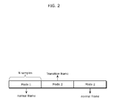
- An example of the transition frame is illustrated in FIG. 2 .
- a pervious frame is coded in the AAC-ELD mode and a current frame is to be coded in the ACELP mode, the current frame is defined as a transition frame.
- the number of processed AAC-ELD frames is 4.
- a frame i-1 is concatenated with three previous frames to form an extended frame with a length of 4N.
- N is the size of the input frame. That is to say, to code a current picture to be coded, the AAC-ELD mode requires not only a sample of the current frame but also samples of the three frames previous to the current frame.
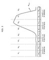
- FIG. 3 illustrates the encoder window shape in the AAC-ELD mode of the encoder.
- the window in the encoder is defined as W enc .
- the encoder window is divided into eight parts, denoted as [w 1 , w 2 , w 3 , w 4 , w 5 , w 6 , w 7 , w 8 ].
- the length of the encoder window is 4N.
- the encoder window in the AAC-ELD mode is designed to match the low delay filter banks used in the AAC-ELD mode.
- one frame is divided into two parts as shown in FIG. 3 .
- the frame i-1 is divided into two vectors [a i-1 , b i-1 ].
- a i-1 has N/2 samples
- b i-1 has N/2 samples. Therefore, the encoder window is applied on the vectors denoted as [a i-4 , b i-4 , a i-3 , b i-3 , a i-2 , b i-2 , a i-1 , b i-1 ], to obtain the windowed signal [a i-4 w 1 , b i-4 w 2 , a i-3 w 3 , b i-3 w 4 , a i-2 w 5 , b i-2 w 6 , a i-1 w 7 , b i-1 w 8 ].
- the low delay filter banks are used to transform the windowed signals.
- the low delay filter banks are defined as following:
- x n [a i-4 W 1 , b i-4 w 2 , a i-3 w 3 , b i-3 w 4 , a i-2 w 5 , b i-2 w 6 , a i-1 w 7 , b i-1 w 8 ].
- the length of the output coefficients is N while the processing frame length is 4N.
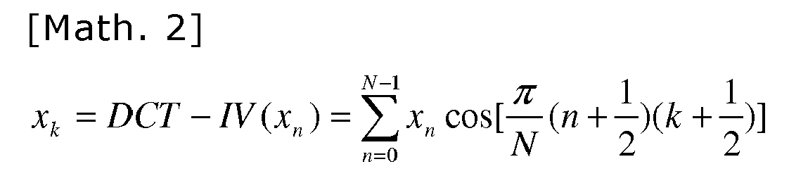
- the low delay filter bank can be expressed in terms of DCT-IV.
- the DCT-IV definition is shown as follows:
- the signal of the frame i-1 transformed by the low delay filter banks can be expressed in term of DCT-IV as follows: [DCT-IV (-(a i-4 w 1 ) R - b i-4 w 2 + (a i-2 w 5 ) R + b i-2 w 6 ), DCT-IV (-a i-3 w 3 + (b i-3 w 4 ) R + a i-1 w 7 - (b i-1 w 8 ) R )], where (a i-4 w 1 ) R , (a i-2 w 5 ) R , (b i-3 w 4 ) R , (b i-1 w 8 ) R denote the reverse order of vectors a i-4 w 1 , a i-2 w 5 , b i-3 w 4 , b i-1 w 8 respectively.
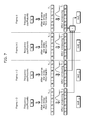
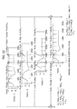
- FIG. 7 illustrates the inverse transform processes in the AAC-ELD mode.
- the inverse low delay filter banks of the AAC-ELD mode in the decoder are shown below.
- the length of the inverse transform signals of the low delay filter banks is 4N.
- the inverse transform signals for the frame i-1 are as follows:
- y i - 1 [ - a i - 4 ⁇ w 1 - b i - 4 ⁇ w 2 R + a i - 2 ⁇ w 5 + b i - 2 ⁇ w 6 R , - a i - 4 ⁇ w 1 R - b i - 4 ⁇ w 2 + a i - 2 ⁇ w 5 R + b i - 2 ⁇ w 6 , - a i - 3 ⁇ w 3 + b i - 3 ⁇ w 4 R + a i - 1 ⁇ w 7 - b i - 1 ⁇ w 8 R , a i - 3 ⁇ w 3 R - i - 3 ⁇ w 4 - a i - 1 ⁇ w 7 R + b i - 1 ⁇ w 8 , a i - 4 ⁇ w 1 + b i
- FIG. 6 illustrates the decoder window shape in the AAC-ELD mode.
- the length of the window in the AAC-ELD mode is 4N. It is the reverse order of the encoder window in the AAC-ELD mode.
- the window in the decoder is denoted as w dec .
- the decoder window is divided into eight parts [w R,8 , w R,7 , w R,6 , w R,5 , w R,4 , w R,3 , w R,2 , w R,1 ] as shown in FIG. 6 .
- the windowed inverse transform signals y ⁇ i - 1 are as follows:
- y ⁇ i - 1 [ - a i - 4 ⁇ w 1 - b i - 4 ⁇ w 2 R + a i - 2 ⁇ w 5 + b i - 2 ⁇ w 6 R ⁇ w R , 8 , - a i - 4 ⁇ w 1 R - b i - 4 ⁇ w 2 + a i - 2 ⁇ w 5 R + b i - 2 ⁇ w 6 ⁇ w R , 7 , - a i - 3 ⁇ w 3 + b i - 3 ⁇ w 4 R + a i - 1 ⁇ w 7 - b i - 1 ⁇ w 8 R ⁇ w R , 6 , a i - 3 ⁇ w 3 R - i - 3 ⁇ w 4 - a i - 1 ⁇ w 7 - b i
- the windowed inverse transform signals y ⁇ i are as follows:
- y ⁇ i [ - a i - 3 ⁇ w 1 - b i - 3 ⁇ w 2 R + a i - 1 ⁇ w 5 + b i - 1 ⁇ w 6 R ⁇ w R , 8 , - a i - 3 ⁇ w 1 R - b i - 3 ⁇ w 2 + a i - 1 ⁇ w 5 R + b i - 1 ⁇ w 6 ⁇ w R , 7 , - a i - 2 ⁇ w 3 + b i - 2 ⁇ w 4 R + a i ⁇ w 7 - b i ⁇ w 8 R ⁇ w R , 6 , a i - 2 ⁇ w 3 R - b i - 2 ⁇ w 4 - a i ⁇ w 7 - b i ⁇ w 8 R ⁇ w R
- FIG. 7 illustrates the overlapping and adding process in the AAC-ELD mode.
- the length of the reconstructed signals out; is N.
- n y ⁇ i , n + y ⁇ i - 1 , n + N + y ⁇ i - 2 , n + 2 ⁇ N + y ⁇ i - 3 , n + 3 ⁇ N , 0 ⁇ n ⁇ N
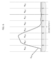
- the aliasing cancellation mechanism of the AAC-ELD is illustrated in FIG. 22 .
- the windowed inverse transform signal of the frame i, the frame i-1, the frame i-2, and the frame i-3 are shown in FIG. 22 .
- the window is designed to possess the following properties:
- a signal a i-1 is reconstructed after the overlapping and adding.
- a signal b i-1 is reconstructed after the overlapping and adding.
- the sound quality of the low delay hybrid codec which uses the AAC-LD is relatively narrowband and is thus not satisfactory although it has low delay compared to when the normal delay AAC is used.
- the AAC-LD mode can be replaced by the AAC-ELD coding mode.
- the AAC-ELD further reduces the delay of the hybrid codec which employs the AAC-LD.
- the other problem of the low delay hybrid codec is the low sound quality, because it lacks a good scheme for coding the transient signal.
- the AAC-ELD uses only one type of window shape which adapts to the low delay filter bank.
- the window shape in the AAC-ELD is long.
- the long window shape of the AAC-ELD causes a poor coding quality for the transient signal.
- a better transient signal coding method for the AAC-ELD is necessary to improve the sound quality of the low delay hybrid codec.
- An object of the present invention is to solve the deterioration in the sound quality caused when different coding modes are switched in the low delay hybrid codec.
- the present invention provides optimal block switching algorithms in an encoder and a decoder for a hybrid speech and audio codec in order to switch coding modes seamlessly to reduce the deterioration in the sound quality caused at the time of switching.
- the switching schemes according to an aspect of the present invention are different from the prior art which processed the aliasing portion of the windowed block differently compared to the subsequent portion of the transition block. That is to say, the non-aliasing portions of the previous frames are processed and used to cancel the aliasing in the current switching frame. No different coding technology is used for different portions of the frames.
- the block switching algorithms are used to handle the transition frames where:
- bitrate of block switching from the ACELP mode to the AAC-ELD mode for the low delay hybrid codec may be reduced.
- the normal MDCT filter bank similar to the low delay filter banks is used for the purpose of reducing the bitrate required for the switching from the ACELP mode to the AAC-ELD mode.
- the sound quality may be improved by designing a block switching scheme for handing the transient signal in the low delay hybrid codec.
- Short windowing may be used for encoding the transient signal because of the abrupt energy change in the transient signal. This allows seamless connection from the short window to the long window in the AAC-ELD mode.
- Embodiment 1 a hybrid speech and audio encoder having block switching algorithms is invented to code a transition frame that is a frame where the AAC-ELD mode is being switched to the ACELP mode.
- the frame size of the ACELP is extended.
- the aliasing which occurs when the AAC-ELD mode is switched to the ACELP mode is attributable to the fact that while the AAC-ELD mode requires a sample of the previous frame to code a current frame to be coded, the ACELP only uses a sample of the current frame, i.e., one frame, to code the current frame.
- the second half of the previous frame preceding the current frame is concatenated with the current frame to form an extended frame, which is longer than a normal input frame size.
- the extended frame is coded in the ACELP mode by the encoder.
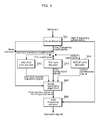
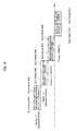
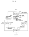
- FIG. 20 is a block diagram illustrating a framework of a hybrid encoder which combines the AAC-ELD coding technology with the ACELP coding technology.
- an incoming signal is sent to a high frequency encoder 2001.
- the coded high frequency parameters are sent to a bit multiplexer block 2006.
- the incoming signal is also sent to a signal classification block 2003.
- the signal classification decides which coding mode is selected for a time domain signal in low frequency band.
- a mode indicator from the signal classification block 2003 is sent to the bit multiplexer block 2006.
- the mode indicator is also used for controlling a block switching algorithm 2002.
- the current time domain signal in low frequency band to be coded is sent to a corresponding encoder 2004, 2005 according to the mode indicator.
- the bit multiplexer block 2006 generates a bitstream.
- the incoming signal is coded on a frame-by-frame basis.
- the input frame size is defined as N in the present embodiment.
- FIG. 20 the block switching algorithms 2002 are used to handle the transition frames where the coding mode is switched.
- FIG. 4 illustrates the block switching algorithm for switching from the AAC-ELD mode to the ACELP mode in Embodiment 1.
- the block switching algorithm concatenates the second half of the previous frame i-1 to form an extended frame having a processing frame length of N + 1 2 ⁇ N .
- This processed frame is sent to the ACELP mode for coding.
- the encoder having the block switching algorithm according to the present embodiment facilitates the aliasing cancellation in the decoder when the coding mode is switched from the AAC-ELD mode to the ACELP mode, and realizes a seamless combination of the AAC-ELD coding technology and the ACELP coding technology in the low delay hybrid speech and audio codec having two coding modes of the audio coding mode and the speech coding mode.
- Embodiment 2 a hybrid speech and audio encoder having block switching algorithms is invented to code the transition frame where the AAC-ELD mode is switched to the ACELP mode.
- Embodiment 2 the principle of Embodiment 2 is to extend the frame length of the ACELP frame.
- the encoder framework is different from Embodiment 1.
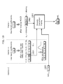
- FIG. 1 illustrates a framework which combines the AAC-ELD that is an audio codec with the ACELP coding technology and the TCX coding technology that are speed codecs.
- an incoming signal is sent to a high frequency encoder 101.
- the coded high frequency parameters are sent to a bit multiplexer block 107.
- the incoming signal is also sent to a signal classification block 103.
- the signal classification decides which coding mode is selected.
- a mode indicator from the signal classification block is sent to the bit multiplexer block 107.
- the mode indicator is also used for controlling a block switching algorithm 102.
- the current time domain signal in low frequency band to be coded is sent to a corresponding encoder 104, 105, 106 according to the mode indicator.
- the bit multiplexer block 107 generates a bitstream.
- the encoder having the block switching algorithm according to the present embodiment facilitates the aliasing cancellation in the decoder when the coding mode is switched from the AAC-ELD mode to the ACELP mode, and realizes a seamless combination of the AAC-ELD coding technology and the ACELP coding technology in the low delay hybrid speech and audio codec having three coding modes.
- Embodiment 3 a hybrid speech and audio decoder having block switching algorithms is invented to decode the transition frame where the AAC-ELD mode is switched to the ACELP mode.
- the current frame is denoted as frame i.
- the block switching algorithms In order to cancel the aliasing of a frame i-1 introduced by the AAC-ELD coding mode, the block switching algorithms generate the inverse aliasing components using the non-aliasing portion of an ACELP synthesized signal of the frame i and a reconstructed signal of a frame i-2.
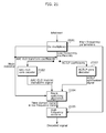
- FIG. 21 illustrates a hybrid speech and audio decoder which combines the AAC-ELD coding technology with the ACELP decoding technologies.
- an input bitstream is de-multiplexed in 2101.
- a mode indicator is sent to control the selecting of the decoding mode and the block switching algorithm 2104.
- High frequency parameters are sent to a high frequency decoder 2105 to reconstruct a high frequency signal.
- the low frequency coefficients are sent to the corresponding decoder 2102 or 2103 according the mode indicator.
- the inverse transform signals and the synthesized signals are sent to the block switching algorithm.
- the block switching algorithm 2104 reconstructs the time domain signal of the low frequency band according to different switching situations.
- the high frequency decoder 2105 reconstructs the signals base on the high frequency parameters and the time domain signal of the low frequency band.
- FIG. 23 illustrates the transition from the AAC-ELD mode to the ACELP mode.
- the frame i-1 is inverse transformed in the AAC-ELD mode as a normal frame.
- the frame i is synthesized in the ACELP mode as a normal frame.
- the non-aliasing portion denoted as a sub-frame 2301 and the decoded signal of the frame i-2 denoted as a sub-frame 2304 and a sub-frame 2305 are processed and used to cancel the aliasing in the aliasing portion denoted as a sub-frame 2302.
- FIG. 8 illustrates one example of the block switching.
- the ACELP synthesized signal is denoted as y i , n acelp , 0 ⁇ n ⁇ 3 2 ⁇ N .
- the length of the ACELP synthesized signal is 3 2 ⁇ N .
- a part of the non-aliasing portion, denoted as the sub-frame 2301 in FIG. 23 is extracted for aliasing cancellation:
- the AAC-ELD inverse transform signals of the previous frame i-1 are denoted as y i-1 with a length of 4N.
- One aliasing portion denoted as the sub-frame 2302 in FIG. 23 is extracted and expressed as follows according to the AAC-ELD inverse transform explained in the background section:
- the window w 8 is applied to the non-aliasing portion b i-1 , as shown in FIG. 8 , to obtain b i-1 w 8 .
- the window w 3 is applied to the non-aliasing portion a i-3 to obtain a i-3 w 3 , as shown in FIG. 8 .
- the window w 4 is applied to the non-aliasing portion b i-3 to obtain b i-3 w 4 , as shown in FIG. 8 .
- the reverse order of b i-3 w 4 is obtained as shown in 901, and is denoted as (b i-3 w 4 ) R .
- components -a i-3 W 3 + (b i-3 w 4 ) R + a i-1 w 7 - (b i-1 w 8 ) R , (b i-1 w 8 ) R , a i-3 w 3 , and (b i-3 w 4 ) R are added as shown in FIG. 8 .
- the outputs of the frame i are signals [a i-1 , b i-1 ] reconstructed by concatenation of the sub-frame 2301 and the sub-frame 801.
- the decoder according to the present embodiment having the block switching algorithm can cancel the aliasing introduced in the transition frame where the AAC-ELD mode is switched to the ACELP mode, by performing signal processing using the non-aliasing portion of the previous frame. This enables a seamless combination of the AAC-ELD coding technology and the ACELP coding technology in the low delay hybrid decoder having two decoding modes.
- Embodiment 4 a hybrid speech and audio decoder having block switching algorithms is invented to decode the transition frame where the AAC-ELD mode is switched to the ACELP mode.
- Embodiment 4 The principle of Embodiment 4 is the same as Embodiment 3.
- the decoder framework is different from Embodiment 3.
- FIG. 5 illustrates the hybrid speech and audio decoder which combines the AAC-ELD coding technology with the ACELP and TCX coding technologies.
- the input bitstream is de-multiplexed in 501.
- a mode indicator is sent to control the selecting one from decoders 502, 503, and 504 and is sent to a block switching algorithm 505.
- the high frequency parameters are sent to a high frequency decoder 506 to reconstruct a high frequency signal.
- the low frequency coefficients are sent to the corresponding decoding mode according the mode indicator.
- the inverse transform signals and synthesized signals are sent to the block switching algorithm 505.
- the block switching algorithm 505 reconstructs the time domain signal of the low frequency band according to different switching situations.
- the high frequency decoder 506 reconstructs the signals base on the high frequency parameters and the time domain signal of the low frequency band.
- the decoder having the block switching algorithm according to the present embodiment solves the aliasing cancellation problem at the transition frame where AAC-ELD mode is switched to the ACELP mode, and realizes a seamless combination of the AAC-ELD coding technology and the ACELP coding technology in the low delay hybrid codec having three decoding modes.
- Embodiment 5 a hybrid speech and audio encoder having block switching algorithm is invented to code the transition frame where the ACELP mode is switched to the AAC-ELD mode.
- the decoding process switches back to the normal AAC-ELD overlapping and adding process.
- this transition frame is coded by normal AAC-ELD low delay filter banks.
- the encoder of the present embodiment uses MDCT filter banks.
- the encoder framework is the same as Embodiment 1.
- the block switching method in the present embodiment is different from Embodiment 1.
- the present embodiment is to code the transition frame where the ACELP mode is switched to the AAC-ELD mode.
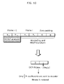
- FIG. 10 illustrates the coding method for the transition frame according to the present embodiment.
- the current frame i [a i , b i ] is extended to the length of 2N by zero padding, denoted as [a i , b i , 0, 0]. Windowing is applied to this vector to obtain a vector [a i w 7 , b i w 8 , 0, 0].
- MDCT filter banks are used to transform the windowed vector:
- the MDCT transform coefficients can be expressed in terms of DCT-IV as follows: a i ⁇ w 7 , b i ⁇ w 8 , 0 , 0
- the coefficients of the portion N/2 are all zero, and thus only the DCT-IV (a i w 7 - (b i w 8 ) R ) having the length of N/2 needs to be sent to the decoder.
- the length of the AAC-ELD coefficients is N. Therefore, by using the method according to the present embodiment, the bitrate is saved by half.
- the encoder according to the present embodiment having the block switching algorithm helps prepare the aliasing components of the frame i in order to perform aliasing cancellation with following frames coded in the AAC-ELD mode, when the coding mode is switched from the ACELP mode to the AAC-ELD mode. It reduces the computation complexity of the coding operation and reduces the bitrate compared to when using the AAC-ELD mode on the transition frame directly.
- Embodiment 6 a hybrid speech and audio encoder having a block switching algorithm is invented to code the transition frame where the ACELP mode is switched to the AAC-ELD mode.
- Embodiment 6 The principle of Embodiment 6 is the same as Embodiment 5, but the encoder framework is different from Embodiment 5.
- Embodiment 6 There are three coding modes in the encoder of Embodiment 6, namely the AAC-ELD mode, the ACELP mode, and the TCX mode.
- the encoder frame work of Embodiment 6 is the same as Embodiment 2.
- Embodiment 7 a hybrid speech and audio decoder with block switching algorithms is invented to decode the transition frame where the ACELP mode is switched to the AAC-ELD mode.
- block switching in the decoder from the ACELP mode to the AAC-ELD mode is performed according to the encoder in Embodiment 5.
- the following frames are switched back to the AAC-ELD overlapping and adding mode.
- Aliasing of the AAC-ELD are produced by using the aliasing portions of the inverse MDCT transform signal of the frame i, the non-aliasing portion of the ACELP synthesized signal of the frame i-1, and the reconstructed signal of the frame i-2 and the frame i-3.
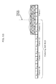
- FIG. 9 illustrates the transition from the ACELP mode to the AAC-ELD mode in the decoder.
- the decoder framework is the same as Embodiment 3.
- the block switching method in the present embodiment is different from Embodiment 3.
- FIGS. 9 , 11 , and 12 illustrate one example of the decoding processes.
- the received low band coefficients are MDCT transform coefficients DCT-IV (a i w 7 - (b i w 8 ) R ) in this transition frame i. Therefore, the corresponding inverse filter banks are IMDCT in Embodiment 7.
- the aliasing outputs of the IMDCT are denoted as [a i w 7 - (b i w 8 ) R , -(a i w 7 ) R + b i w 8 ] having a length of N, shown as a sub-frame 901 and a sub-frame 902 in FIG. 9 .
- the non-aliasing portions of ACELP synthesized signals from the previous frame i-1 are denoted as [a i-1 , b i-1 ] having a length of N, shown as a sub-frame 903 and a sub-frame 904 in FIG. 9 .
- the outputs of the previous two frames are denoted as [a i-2 , b i-2 ] and [a i-3 , b i-3 ], shown as sub-frames 905, 906, 907, and 908, respectively in FIG. 9 .
- the aliasing portions of the inverse AAC-ELD are produced by using the sub-frames mentioned above.
- the purpose is to prepare the aliasing components for overlapping and adding with the following frames coded in the AAC-ELD mode, so that the coding mode can switch back to the normal AAC-ELD mode.
- FIGS. 11 and 12 illustrate the detail processes of how to produce the aliasing elements of the AAC-ELD.
- the decoded signal of a frame i-3 a i-3 is windowed to obtain a i-3 w 1 .
- Folding is applied to obtain the reverse order (a i-3 w 1 ) R .
- the second half of the decoded signal of the frame i-3 b i-3 is windowed to obtain b i-3 w 2 .
- the first part of the non-aliasing portion of the ACELP synthesized signal a i-1 of the frame i-1 is windowed to obtain a i-1 w 5 . Folding is applied to obtain the reverse order (a i-1 w 5 ) R .
- the second part of the non-aliasing portion of the ACELP synthesized signal is denoted as b i-1 . Windowed is applied to b i-1 to obtain b i-1 w 6 .
- A - a i - 3 ⁇ w 1 R - b i - 3 ⁇ w 2 + a i - 1 ⁇ w 5 R + b i - 1 ⁇ w 6
- a R - a i - 3 ⁇ w 1 - b i - 3 ⁇ w 2 R + a i - 1 ⁇ w 5 + b i - 1 ⁇ w 6 R - A
- R a i - 3 ⁇ w 1 + b i - 3 ⁇ w 2 R - a i - 1 ⁇ w 5 - b i - 1 ⁇ w 6
- R - A a i - 3 ⁇ w 1 R + b i - 3 ⁇ w 2 - a i - 1 ⁇ w 5 - b i - 1 ⁇ w 6
- A a i - 3 ⁇ w 1 R +
- FIG. 12 illustrates the detail of the processes of producing the aliasing portions of the AAC-ELD.
- the aliasing portions of the AAC-ELD frame i are obtained, as shown in FIG. 12 .
- y i R A , A , B , R - B , R - A , - A , - B , R B
- Decoder window [w R,8 , w R,7 , w R,6 , w R,5 , w R,4 , w R,3 , w R,2 , w R,1 ] is applied to obtain the windowed aliasing portions: y ⁇ i
- the aliasing cancellation with following AAC-ELD frames can be continued.
- the decoder according to the present embodiment having the block switching algorithm generates the aliasing components of the AAC-ELD mode using the MDCT coefficients, to facilitate the aliasing cancellation with the following frames coded in the AAC-ELD mode. According to an aspect of the present invention, it is possible to realize a seamless transition from the ACELP mode to the AAC-ELD mode in the low delay hybrid speech and audio codec having two coding modes.
- Embodiment 8 a hybrid speech and audio decoder having block switching algorithms is invented to decode the transition frame where the ACELP mode is switched to the AAC-ELD mode.
- Embodiment 8 The principle of Embodiment 8 is the same as Embodiment 7.
- the decoder framework is different from Embodiment 7.
- Embodiment 8 There are three decoding modes in Embodiment 8, namely the AAC-ELD mode, the ACELP mode, and the TCX mode.
- the frame work of Embodiment 8 is the same as Embodiment 4.
- the decoder according to the present embodiment having the block switching algorithm generates the aliasing of the AAC-ELD mode to facilitate the aliasing cancellation with the following frames coded in the AAC-ELD mode. According to an aspect of the present invention, it is possible to realize a seamless transition from the ACELP mode to the AAC-ELD mode in the low delay hybrid speech and audio codec having three coding modes.
- Embodiment 9 a speech and audio encoder having a block switching algorithm is invented to code the transition frame where the AAC-ELD mode is switched to the TCX mode.
- the TCX frame size is extended.
- the block switching algorithms concatenate the current frame with the previous frame to form an extended frame, whose length is longer than the normal frame size. This extended frame is coded in the TCX mode in the encoder.
- the encoder frame work is the same as Embodiment 2.
- the block switching method in the present embodiment is different from Embodiment 2.
- the present embodiment is to code the transition frame where the AAC-ELD mode is switched to the TCX mode.
- FIG. 13 illustrates the coding process.
- the previous frame is coded in the AAC-ELD mode.
- the current frame i is concatenated with the previous frame i-1 to form a long frame.
- the processing frame size is 2N, where N is the frame size.
- the extended frame is coded in the TCX mode as shown in FIG. 13 .
- the window size of the TCX mode is N.
- the overlapping length of the TCX mode is 1 2 ⁇ N Therefore, the extended frame contains three TCX windows as shown in FIG. 13 .
- the encoder according to the present embodiment having the block switching algorithm facilitates the aliasing cancellation in the decoder when the coding mode is switched from the AAC-ELD mode to the TCX mode, and realizes a seamless combination of the AAC-ELD coding technology and the TCX coding technology in the low delay hybrid speech and audio codec having three coding modes.
- Embodiment 10 a hybrid speech and audio decoder having a block switching algorithm is invented to decode the transition frame where the AAC-ELD mode is switched to the TCX mode.
- the current frame is denoted as the frame i.
- the block switching algorithm In order to cancel the aliasing of the frame i-1 introduced by the AAC-ELD mode, the block switching algorithm generates the inverse aliasing components using the TCX synthesized signal of the frame i and the reconstructed signal of the frame i-2.
- the decoder framework is the same as Embodiment 4.
- the block switching method in the present embodiment is different from Embodiment 4.
- FIG. 14 illustrates the block switching process.
- the current transition frame is coded in the TCX mode using a processing frame size of 2N, where N is the frame size.
- the TCX synthesis is used to synthesize in the decoder.
- the TCX synthesized signals are [a i-1 + aliasing, b i-1 , a i , b i + aliasing] with a length of 2N.
- the non-aliasing portion b i-1 shown as a sub-frame 1401 in FIG. 14 , is used for generation the aliasing component of a sub-frame 1402.
- the AAC-ELD synthesized signals of the previous frame i-1 is denoted as y i-1 , and has a length of 4N.
- the y i-1 is shown as follows:
- y i - 1 [ - a i - 4 ⁇ w 1 - b i - 4 ⁇ w 2 R + a i - 2 ⁇ w 5 + b i - 2 ⁇ w 6 R , - a i - 4 ⁇ w 1 R - b i - 4 ⁇ w 2 + a i - 2 ⁇ w 5 R + b i - 2 ⁇ w 6 , - a i - 3 ⁇ w 3 + b i - 3 ⁇ w 4 R + a i - 1 ⁇ w 7 - b i - 1 ⁇ w 8 R , a i - 3 ⁇ w 3 R - i - 3 ⁇ w 4 - a i - 1 ⁇ w 7 R + b i - 1 ⁇ w 8 , a i - 4 ⁇ w 1 + b i
- the AAC-ELD aliasing component -a i-3 w 3 + (b i-3 w 4 ) R + a i-1 w 7 - (b i-1 w 8 ) R , shown as the sub-frame 1402, is cancelled by using the TCX synthesized signal b i-1 sub-frame 1401, and the reconstructed signal of i-2 out i-2 [a i-3 , b i-3 ], shown as sub-frame 1403 and 1040.
- the transition frame is reconstructed.
- the details of the aliasing cancellation processes in FIG. 14 are the same as the description of FIG. 8 .
- the sub-frame 2301 in FIG. 23 is replaced by the non-aliasing portion b i-1 1401.
- the sub-frame 2302 that is the aliasing portion is replaced by 1402 in FIG. 14 .
- the reconstructed signal of the transition frame i is [a i-1 , b i-1 ].
- the decoder according to the present embodiment having the block switching algorithm cancels the aliasing of the frame i-1 introduced by the AAC-ELD mode. This enables a seamless transition from the AAC-ELD mode to the TCX mode in the low delay hybrid speech and audio codec.
- Embodiment 11 a hybrid speech and audio encoder having a block switching algorithm is invented to code the transition frame where the TCX mode is switched to the AAC-ELD mode.
- the current transition frame is denoted as the frame i and it is coded in the AAC-ELD mode.
- the previous frame is coded in the TCX mode.
- the block switching algorithm codes the current frame together with three previous frames in the AAC-ELD mode.
- the encoder framework is the same as Embodiment 2.
- the block switching method in the present embodiment is different from Embodiment 2.
- FIG. 15 illustrates the coding process for the transition frame where the TCX mode is switched to the AAC-ELD mode in the encoder.
- the length of overlapping, in the TCX mode is 1 2 ⁇ N where N is the frame size.
- two TCX windows are applied as shown in FIG. 15 .
- the AAC-ELD mode is directly applied as shown in FIG. 15 .
- the encoder in Embodiment 11 facilitates the aliasing cancelling performed in the decoder when the TCX mode is switched to the AAC-ELD mode.
- the block switching algorithm in the present embodiment realizes the seamless combination of the AAC-ELD coding technology and the TCX coding technology in the low delay hybrid speech and audio codec.
- Embodiment 12 a hybrid speech and audio decoder having a block switching algorithm is invented to decode the transition frame where the TCX mode is switched to the AAC-ELD mode.
- the block switching algorithm in the present embodiment generates the aliasing of the AAC-ELD using the TCX synthesized signals and the reconstructed signal of the frame i-2, and cancels the aliasing of the AAC-ELD for the block switching purpose.
- FIG. 16 illustrates the corresponding decoding processes for the transition frame where the TCX mode is switched to the AAC-ELD mode.
- the previous frame is coded in the TCX mode.
- the TCX synthesized signals are [b i-2 + aliasing, a i-1 , b i-1 + aliasing], and have a length of 3 2 ⁇ N a i-1 is shown as a sub-frame 1601 in FIG. 16 .
- the inverse transform signal is denoted as y i and has a length of 4N as shown below.
- the aliasing portion - (a i-3 w 1 )R - b i-3 w 2 + (a i-1 w 5 ) R + b i-1 w 6 , shown as a sub-frame 1602, is cancelled by the TCX synthesized signal a i-1 and the frame i-2 out i-2 [a i-3 , b i-3 ] of the reconstructed signal shown as sub-frames 1603 and 1604 to reconstruct the signal of the transition frame [a i-1 , b i-1 ].
- FIG. 17 illustrates one example of aliasing cancellation.
- the reconstructed signal of the frame i-2 a i-3 is windowed to obtain a i-3 w 1 as shown in FIG. 17 .
- the reverse vector of a i-3 w 1 is denoted as (a i-3 w 1 ) R .
- the second half of the out i-2 is windowed to obtain b i-3 w 2 .
- the TCX synthesized signal a i-1 is windowed to obtain a i-1 w 5 .
- the reverse order of a i-1 w 5 is (a i-1 w 5 ) R .
- a sub-frame 1701 b i-1 is reconstructed.
- the sub-frame 1701 is concatenated with the sub-frame 1601 as shown in FIG. 17 .
- FIG. 24 is illustrates the sub-frame border smoothing processes.
- the sub-frame 1701 b i-1 is windowed by the TCX window shape. Folding and unfolding processes are applied to generate the MDCT-TCX aliasing components. The outcome is overlapped with the aliasing portions of the sub-frame 1605, which are originally from the MDCT-TCX inverse transform, to obtain a sub-frame 2401. The border between the sub-frames 1601 and 2401 is smoothed by the overlapping and adding processes. The transient signal [a i-1 , b i-1 ] is reconstructed.
- the decoder according to the present embodiment having the block switching algorithm cancels the aliasing of the frame i introduced by the AAC-ELD mode. This enables a seamless transition from the TCX mode to the AAC-ELD mode.
- Embodiment 13 a coding method for coding the transient signal in the low delay hybrid speech and audio codec is invented.
- a transient signal coding algorithm is invented in the present embodiment.
- the current frame i having a transient signal is concatenated with the previous frame to form an extended frame having a longer frame size.
- Multiple short windows and an MDCT filter bank are used to code this processed frame.
- FIG. 18 illustrates the coding processed in the encoder.
- the previous frame i-1 is coded together with three previous frames in the AAC-ELD mode.
- the frame i is concatenated with the previous frame as shown in FIG. 18 .
- the length of the long extended transient frame is N + 1 2 ⁇ N + 1 4 ⁇ N .
- Six short windows having a length of 1 2 ⁇ N are applied on the extended frame.
- the shape of the short window can be any symmetric window used by the MDCT filter banks.
- the MDCT filer banks are applied to short windowed signals.
- the encoder according to the present embodiment provides the transient signal handling algorithm to improve the sound quality of the low delay hybrid codec which uses the AAC-ELD coding technology.
- Embodiment 14 a hybrid speech and audio decoder for decoding the transient signal is invented.
- the transient frame i is coded by the short window MDCT as explained in Embodiment 13.
- the transient decoding method in the present embodiment uses the inverse MDCT transform signal of the frame i and the reconstructed signal of the frame i-3 to generate the inverse aliasing of the AAC-ELD mode.
- a signal 1902 is [a i-1 + aliasing, b i-1 , a i , b i + aliasing] with a length of N + 1 2 ⁇ N + 1 4 ⁇ N .
- the processes of the block 1901 in FIG. 19 are the same as FIG. 8 .
- the sub-frame 2301 in FIG. 23 is replaced by the non-aliasing portion 1902.
- the sub-frame 2302 that is the aliasing portion is replaced by 1904 in FIG. 19 .
- the invented decoder provides a transient signal handling method to improve the coding performance of the transient signal. As a result, the sound quality of the low delay hybrid codec which employs the AAC-ELD coding technology is improved.
- the present invention relates, in general, to hybrid audio coding systems, and is more particularly related to hybrid coding systems which support audio coding and speech coding in low bitrate.
- the hybrid coding system combines the transform coding and the time domain coding. It can be used in broadcasting systems, mobile
Landscapes
- Engineering & Computer Science (AREA)
- Physics & Mathematics (AREA)
- Multimedia (AREA)
- Health & Medical Sciences (AREA)
- Audiology, Speech & Language Pathology (AREA)
- Human Computer Interaction (AREA)
- Signal Processing (AREA)
- Acoustics & Sound (AREA)
- Computational Linguistics (AREA)
- Spectroscopy & Molecular Physics (AREA)
- General Physics & Mathematics (AREA)
- Algebra (AREA)
- Mathematical Analysis (AREA)
- Mathematical Optimization (AREA)
- Mathematical Physics (AREA)
- Pure & Applied Mathematics (AREA)
- Theoretical Computer Science (AREA)
- Quality & Reliability (AREA)
- Compression, Expansion, Code Conversion, And Decoders (AREA)
Abstract
Description
- The present invention relates to a hybrid audio encoder and a hybrid audio decoder which perform coding or decoding while switching between different codecs.
- Speech codec is designed specially according to the characteristics of a speech signal [NPL 1]. The speech codec has the advantage of efficiently coding a speech signal. For example, the sound quality is high when a speech signal is coded in low bitrate, and the delay is low. However, the sound quality in coding an audio signal that is wideband compared to the speech signal is not as good as in the case of using some transform codecs such as the AAC scheme. On the other hand, the transform codec represented by the AAC scheme is suitable for coding an audio signal, but it requires higher bitrate to code a speech signal in order to achieve the same sound quality as the speech codec. The hybrid codec can code a speech signal and an audio signal with high sound quality at low bitrate. The hybrid codec combines the merits of the two different codecs in order to achieve coding with high sound quality at low bitrate.
- A low delay hybrid codec is desired for real-time communication applications such as a teleconference system. One low delay hybrid codec combines the AAC-LD (low-delay AAC) coding technology with the speech coding technology. The AAC-LD provides a mode with an algorithm delay not exceeding 20 ms. The AAC-LD is derived from the normal AAC coding technology. In order to reduce the algorithm delay, the AAC-LD has some modifications on AAC. Firstly, the frame size of the AAC-LD is reduced to 1024 or 960 time domain samples, and thus the output spectral values of the MDCT filter bank are reduced to 512 and 480 spectral values, respectively. Secondly, in order to reduce the algorithm delay, look-ahead is disabled, and as a result, block switching is not used. Thirdly, a low-overlap window is used to replace the Kaiser-Bessel window used in the window function processing in the normal delay AAC. The low-overlap window is used for efficiently coding transient signals in the AAC-LD. Fourthly, the bit reservoir is minimized or not used at all. Fifthly, the temporal noise shaping and long-term prediction functions are adapted according to the low delay frame size.
- Generally, the speech codec is based on linear prediction coding (algebraic code-excited linear prediction (ACELP)) [NPL 1]. For the ACELP coding, a linear prediction analysis is applied on a speech signal, and an algebraic codebook is used to code an excitation signal calculated by the linear prediction analysis. To further improve the sound quality of the ACELP coding, recent speech codec additionally uses the transform coded excitation coding (TCX coding). For the TCX coding, after linear prediction analysis, transform coding is applied on the excitation signal. The Fourier transformed weighted signal is quantized using algebraic vector quantization. Different frame sizes are available for speech codec, for example, 1024 time domain samples, 512 time domain samples, and 256 time domain samples. The coding mode is selected using the closed-loop analysis-by-synthesis method.
- A low delay hybrid codec has three different coding modes, namely, the AAC-LD coding mode, the ACELP mode and the TCX mode. Since each mode codes a signal in a different domain and has a different frame size, the hybrid codec needs to have block switching methods for transition frames in which the coding mode switches. An example of the transition frame is illustrated in
FIG. 2 . For example, a pervious frame is coded in the AAC-ELD mode and a current frame is to be coded in the ACELP mode, the current frame is defined as a transition frame. In the prior art, to switch between different coding modes, the aliasing portion of the previous windowed frame is processed differently compared to the current portion of the current block in the transition frame (PTL 1: International Patent Application PublicationWO2010/003532 by Fraunhofer Gesellschaft). - To facilitate the explanation of the present invention in the following sections, the transform and the inverse transform of the AAC-ELD is provided in this background section.
- The transform processes of the AAC-ELD mode in the encoder are described as follows:
- The number of processed AAC-ELD frames is 4. A frame i-1 is concatenated with three previous frames to form an extended frame with a length of 4N. Here, N is the size of the input frame. That is to say, to code a current picture to be coded, the AAC-ELD mode requires not only a sample of the current frame but also samples of the three frames previous to the current frame.
- Firstly, window is applied on the extended frame in the AAC-ELD mode.
FIG. 3 illustrates the encoder window shape in the AAC-ELD mode of the encoder. The window in the encoder is defined as Wenc. For the convenience of illustration, the encoder window is divided into eight parts, denoted as [w1, w2, w3, w4, w5, w6, w7, w8]. The length of the encoder window is 4N. The encoder window in the AAC-ELD mode is designed to match the low delay filter banks used in the AAC-ELD mode. For the convenience of explanation, one frame is divided into two parts as shown inFIG. 3 . For example, the frame i-1 is divided into two vectors [ai-1, bi-1]. Here, ai-1 has N/2 samples, and bi-1 has N/2 samples. Therefore, the encoder window is applied on the vectors denoted as [ai-4, bi-4, ai-3, bi-3, ai-2, bi-2, ai-1, bi-1], to obtain the windowed signal [ai-4w1, bi-4w2, ai-3w3, bi-3w4, ai-2w5, bi-2w6, ai-1w7, bi-1w8]. - Next, the low delay filter banks are used to transform the windowed signals. The low delay filter banks are defined as following:
-

- where xn = [ai-4W1, bi-4w2, ai-3w3, bi-3w4, ai-2w5, bi-2w6, ai-1w7, bi-1w8].
- According to the above low delay filter banks, the length of the output coefficients is N while the processing frame length is 4N.
- The low delay filter bank can be expressed in terms of DCT-IV. The DCT-IV definition is shown as follows:
-
- According to the following identities:

-

- the signal of the frame i-1 transformed by the low delay filter banks can be expressed in term of DCT-IV as follows:
[DCT-IV (-(ai-4w1)R - bi-4w2 + (ai-2w5)R+ bi-2w6),
DCT-IV (-ai-3w3 + (bi-3w4)R + ai-1w7 - (bi-1w8)R)],
where (ai-4w1)R, (ai-2w5)R, (bi-3w4)R, (bi-1w8)R denote the reverse order of vectors ai-4w1, ai-2w5, bi-3w4, bi-1w8 respectively. - The inverse transform processes in the AAC-ELD mode of the decoder are described below.
- The following describes the case where the decoder decodes the frame i-1 in the AAC-ELD mode.
FIG. 7 illustrates the inverse transform processes in the AAC-ELD mode. The inverse low delay filter banks of the AAC-ELD mode in the decoder are shown below. -

- The length of the inverse transform signals of the low delay filter banks is 4N. As explained in
Embodiment 1, the inverse transform signals for the frame i-1 are as follows: -

- After applying inverse low delay filter banks, window is applied on yi-1 to obtain

FIG. 6 illustrates the decoder window shape in the AAC-ELD mode. The length of the window in the AAC-ELD mode is 4N. It is the reverse order of the encoder window in the AAC-ELD mode. The window in the decoder is denoted as wdec. For the convenience of illustration, the decoder window is divided into eight parts [wR,8, wR,7, wR,6, wR,5, wR,4, wR,3, wR,2, wR,1] as shown inFIG. 6 . - The windowed inverse transform signals

are as follows: -

- For the next frame i coded in the AAC-ELD mode, the windowed inverse transform signals
are as follows: -

- In order to reconstruct the signal [ai-1, bi-1] of the frame i, the overlapping and adding process requires three previous frames.
FIG. 7 illustrates the overlapping and adding process in the AAC-ELD mode. The length of the reconstructed signals out; is N. - The overlapping and adding processes can be expressed as the following equation:
-

- The aliasing cancellation mechanism of the AAC-ELD is illustrated in
FIG. 22 . The windowed inverse transform signal of the frame i, the frame i-1, the frame i-2, and the frame i-3 are shown inFIG. 22 . For the purpose of visualization, the graphs show an example of a special case where
-

- The window is designed to possess the following properties:
-

- A signal ai-1 is reconstructed after the overlapping and adding.
- The same analysis method is used to reconstruct a signal bi-1.
-
-

- A signal bi-1 is reconstructed after the overlapping and adding.
-
- [PTL 1] Fuchs, Guillaume "Apparatus and method for encoding/decoding and audio signal using an aliasing switch scheme", International Patent Application Publication
W02010/003532 -
- [NPL 1] Milan Jelinek, "Wideband Speech Coding Advances in VMR-WB Standard", IEEE Transactions on Audio, Speech and Language Processing, Vol. 15, No. 4, May 2007
- The sound quality of the low delay hybrid codec which uses the AAC-LD is relatively narrowband and is thus not satisfactory although it has low delay compared to when the normal delay AAC is used.
- To improve the sound quality (in particular, to increase the bandwidth of the sound) of the hybrid codec, the AAC-LD mode can be replaced by the AAC-ELD coding mode. The AAC-ELD further reduces the delay of the hybrid codec which employs the AAC-LD.
- However, there are problems with building a hybrid codec using the AAC-ELD. With the AAC-ELD, a frequency conversion is performed using a sample overlapping with a previous frame, whereas with the ACELP mode and the TCX mode, the coding can be completed with a sample of the current frame only. Thus, when switching between different coding modes, e.g., between the AAC-ELD mode and the ACELP or TCX mode, aliasing is introduced in the transition frames where the mode is switched. The aliasing results in unnatural sound. With the block switching algorithms in the prior art, the aliasing cannot be cancelled because the coding structure of the low delay hybrid codec which employs the AAC-ELD is different from other hybrid codecs in the prior art. In the prior art, the block switching algorithms are designed to switch between the AAC-LD mode and the ACELP or TCX mode. Without any modification, these algorithms are not applicable to the block switching between the AAC-ELD mode and the ACELP or TCX mode.
- That is to say, in order to seamlessly combine the AAC-ELD coding technology with the ACELP and TCX coding technologies in a low delay hybrid codec to reduce deterioration in the sound quality attributable to the aliasing, new block switching algorithms are needed to handle the transition frame where the coding mode is switched.
- The other problem of the low delay hybrid codec is the low sound quality, because it lacks a good scheme for coding the transient signal. The AAC-ELD uses only one type of window shape which adapts to the low delay filter bank. The window shape in the AAC-ELD is long. The long window shape of the AAC-ELD causes a poor coding quality for the transient signal. A better transient signal coding method for the AAC-ELD is necessary to improve the sound quality of the low delay hybrid codec.
- An object of the present invention is to solve the deterioration in the sound quality caused when different coding modes are switched in the low delay hybrid codec.
- The present invention provides optimal block switching algorithms in an encoder and a decoder for a hybrid speech and audio codec in order to switch coding modes seamlessly to reduce the deterioration in the sound quality caused at the time of switching. The switching schemes according to an aspect of the present invention are different from the prior art which processed the aliasing portion of the windowed block differently compared to the subsequent portion of the transition block. That is to say, the non-aliasing portions of the previous frames are processed and used to cancel the aliasing in the current switching frame. No different coding technology is used for different portions of the frames.
- The block switching algorithms are used to handle the transition frames where:
- the AAC-ELD mode is switched to the ACELP mode;
- the ACELP mode is switched to the AAC-ELD mode;
- the AAC-ELD mode is switched to the TCX mode; or
- the TCX mode is switched to the AAC-ELD mode.
- Furthermore, the bitrate of block switching from the ACELP mode to the AAC-ELD mode for the low delay hybrid codec may be reduced. Instead of using the low delay filter banks, the normal MDCT filter bank similar to the low delay filter banks is used for the purpose of reducing the bitrate required for the switching from the ACELP mode to the AAC-ELD mode.
- Moreover, the sound quality may be improved by designing a block switching scheme for handing the transient signal in the low delay hybrid codec. Short windowing may be used for encoding the transient signal because of the abrupt energy change in the transient signal. This allows seamless connection from the short window to the long window in the AAC-ELD mode.
-
- [
FIG. 1] FIG. 1 is a block diagram illustrating a framework of a low delay hybrid encoder having three encoding modes. - [
FIG. 2] FIG. 2 is a diagram illustrating a transition frame where a normal frame is switched to another normal frame. - [
FIG. 3] FIG. 3 is a diagram illustrating windowing by an encoder in the AAC-ELD mode. - [
FIG. 4] FIG. 4 is a diagram illustrating a frame border when the AAC-ELD mode is switched to the ACELP mode in an encoder. - [
FIG. 5] FIG. 5 is a block diagram illustrating a low delay hybrid decoder having three decoding modes. - [
FIG. 6] FIG. 6 is a diagram illustrating windowing by a decoder in the AAC-ELD mode. - [
FIG. 7] FIG. 7 is a diagram illustrating decoding processes in the AAC-ELD mode. - [
FIG. 8] FIG. 8 is a diagram illustrating decoding processes for switching from the AAC-ELD mode to the ACELP mode. - [
FIG. 9] FIG. 9 is a diagram illustrating a process for switching from the ACELP mode to the AAC-ELD mode in a decoder. - [
FIG. 10] FIG. 10 is a diagram illustrating a process for switching from the ACELP mode to the AAC-ELD mode in an encoder. - [
FIG. 11] FIG. 11 is a diagram illustrating Example 1 of decoding processes for switching from the ACELP mode to the AAC-ELD mode. - [
FIG. 12] FIG. 12 is a diagram illustrating Example 2 of decoding processes for switching from the ACELP mode to the AAC-ELD mode. - [
FIG. 13] FIG. 13 is a diagram illustrating a process for switching from the AAC-ELD mode to the TCX mode in an encoder. - [
FIG. 14] FIG. 14 is a diagram illustrating a process for switching from the AAC-ELD mode to the TCX mode in a decoder. - [
FIG. 15] FIG. 15 is a diagram illustrating a process for switching from the TCX mode to the AAC-ELD mode in an encoder. - [
FIG. 16] FIG. 16 is a diagram illustrating a decoding process for switching from the TCX mode to the AAC-ELD mode. - [
FIG. 17] FIG. 17 is a diagram illustrating details of a decoding process for switching from the TCX mode to the AAC-ELD mode. - [
FIG. 18] FIG. 18 is a diagram illustrating a process on a transient signal in an encoder. - [
FIG. 19] FIG. 19 is a diagram illustrating a decoding process on a transient signal. - [
FIG. 20] FIG. 20 is a block diagram illustrating a framework of a low delay hybrid encoder having two encoding modes. - [
FIG. 21] FIG. 21 is a block diagram illustrating a framework of a low delay hybrid decoder having two decoding modes. - [
FIG. 22] FIG. 22 is a diagram illustrating an aliasing canceling process in the AACC-ELD mode. - [
FIG. 23] FIG. 23 is a diagram illustrating a process for switching from the AAC-ELD mode to the ACELP mode in a decoder. - [
FIG. 24] FIG. 24 is a diagram illustrating a smoothing process at a sub-frame border. - The following embodiments illustrate the principles of various inventive steps. Variations of the specific examples described herein will be apparent to those skilled in the art.
- In
Embodiment 1, a hybrid speech and audio encoder having block switching algorithms is invented to code a transition frame that is a frame where the AAC-ELD mode is being switched to the ACELP mode. - In order to cancel previous frame's aliasing introduced by the AAC-ELD mode in the decoder, the frame size of the ACELP is extended. The aliasing which occurs when the AAC-ELD mode is switched to the ACELP mode is attributable to the fact that while the AAC-ELD mode requires a sample of the previous frame to code a current frame to be coded, the ACELP only uses a sample of the current frame, i.e., one frame, to code the current frame. In contrast, the second half of the previous frame preceding the current frame is concatenated with the current frame to form an extended frame, which is longer than a normal input frame size. The extended frame is coded in the ACELP mode by the encoder.
-
FIG. 20 is a block diagram illustrating a framework of a hybrid encoder which combines the AAC-ELD coding technology with the ACELP coding technology. InFIG. 20 , an incoming signal is sent to ahigh frequency encoder 2001. The coded high frequency parameters are sent to abit multiplexer block 2006. The incoming signal is also sent to asignal classification block 2003. The signal classification decides which coding mode is selected for a time domain signal in low frequency band. A mode indicator from thesignal classification block 2003 is sent to thebit multiplexer block 2006. The mode indicator is also used for controlling ablock switching algorithm 2002. The current time domain signal in low frequency band to be coded is sent to acorresponding encoder bit multiplexer block 2006 generates a bitstream. - The incoming signal is coded on a frame-by-frame basis. The input frame size is defined as N in the present embodiment.
- In
FIG. 20 , theblock switching algorithms 2002 are used to handle the transition frames where the coding mode is switched.FIG. 4 illustrates the block switching algorithm for switching from the AAC-ELD mode to the ACELP mode inEmbodiment 1. - The block switching algorithm concatenates the second half of the previous frame i-1 to form an extended frame having a processing frame length of

This processed frame is sent to the ACELP mode for coding. - The encoder having the block switching algorithm according to the present embodiment facilitates the aliasing cancellation in the decoder when the coding mode is switched from the AAC-ELD mode to the ACELP mode, and realizes a seamless combination of the AAC-ELD coding technology and the ACELP coding technology in the low delay hybrid speech and audio codec having two coding modes of the audio coding mode and the speech coding mode.
- In
Embodiment 2, a hybrid speech and audio encoder having block switching algorithms is invented to code the transition frame where the AAC-ELD mode is switched to the ACELP mode. - As in
Embodiment 1, the principle ofEmbodiment 2 is to extend the frame length of the ACELP frame. The encoder framework is different fromEmbodiment 1. There are three coding modes in the encoder according toEmbodiment 2. They are the AAC-ELD mode, the ACELP mode, and the TCX mode. -
FIG. 1 illustrates a framework which combines the AAC-ELD that is an audio codec with the ACELP coding technology and the TCX coding technology that are speed codecs. InFIG. 1 , an incoming signal is sent to ahigh frequency encoder 101. The coded high frequency parameters are sent to a bitmultiplexer block 107. The incoming signal is also sent to asignal classification block 103. The signal classification decides which coding mode is selected. A mode indicator from the signal classification block is sent to the bitmultiplexer block 107. The mode indicator is also used for controlling ablock switching algorithm 102. The current time domain signal in low frequency band to be coded is sent to acorresponding encoder multiplexer block 107 generates a bitstream. - The encoder having the block switching algorithm according to the present embodiment facilitates the aliasing cancellation in the decoder when the coding mode is switched from the AAC-ELD mode to the ACELP mode, and realizes a seamless combination of the AAC-ELD coding technology and the ACELP coding technology in the low delay hybrid speech and audio codec having three coding modes.
- In
Embodiment 3, a hybrid speech and audio decoder having block switching algorithms is invented to decode the transition frame where the AAC-ELD mode is switched to the ACELP mode. - In present embodiment, the current frame is denoted as frame i. In order to cancel the aliasing of a frame i-1 introduced by the AAC-ELD coding mode, the block switching algorithms generate the inverse aliasing components using the non-aliasing portion of an ACELP synthesized signal of the frame i and a reconstructed signal of a frame i-2.
-
FIG. 21 illustrates a hybrid speech and audio decoder which combines the AAC-ELD coding technology with the ACELP decoding technologies. InFIG. 21 , an input bitstream is de-multiplexed in 2101. A mode indicator is sent to control the selecting of the decoding mode and theblock switching algorithm 2104. High frequency parameters are sent to ahigh frequency decoder 2105 to reconstruct a high frequency signal. The low frequency coefficients are sent to the correspondingdecoder block switching algorithm 2104 reconstructs the time domain signal of the low frequency band according to different switching situations. Thehigh frequency decoder 2105 reconstructs the signals base on the high frequency parameters and the time domain signal of the low frequency band. - In
Embodiment 3, a block switching method for switching from the AAC-ELD mode to the ACELP mode in the decoder is invented.FIG. 23 illustrates the transition from the AAC-ELD mode to the ACELP mode. The frame i-1 is inverse transformed in the AAC-ELD mode as a normal frame. The frame i is synthesized in the ACELP mode as a normal frame. The non-aliasing portion denoted as asub-frame 2301 and the decoded signal of the frame i-2 denoted as asub-frame 2304 and asub-frame 2305 are processed and used to cancel the aliasing in the aliasing portion denoted as asub-frame 2302. -
FIG. 8 illustrates one example of the block switching. - For the frame i, the ACELP synthesized signal is denoted as

According to the encoding processes illustrated inEmbodiment 1, the length of the ACELP synthesized signal is
A part of the non-aliasing portion, denoted as thesub-frame 2301 inFIG. 23 , is extracted for aliasing cancellation: -

- The AAC-ELD inverse transform signals of the previous frame i-1 are denoted as yi-1 with a length of 4N. One aliasing portion denoted as the
sub-frame 2302 inFIG. 23 is extracted and expressed as follows according to the AAC-ELD inverse transform explained in the background section: -
- The non-aliasing portion 2301 bi-1, the
aliasing portion 2302 of the frame i-1 - ai-3w3 + (bi-3w4)R + ai-1w7 - (bi-1w8)R, and thesub-frames - The window w8 is applied to the non-aliasing portion bi-1, as shown in
FIG. 8 , to obtain bi-1w8. - After windowing, folding is applied to obtain the reverse order of bi-1w8, denoted as (bi-1w8)R.
- The window w3 is applied to the non-aliasing portion ai-3 to obtain ai-3w3, as shown in
FIG. 8 . - The window w4 is applied to the non-aliasing portion bi-3 to obtain bi-3w4, as shown in
FIG. 8 . The reverse order of bi-3w4 is obtained as shown in 901, and is denoted as (bi-3w4)R. - To cancel the aliasing, components -ai-3W3 + (bi-3w4)R + ai-1w7 - (bi-1w8)R, (bi-1w8)R, ai-3w3, and (bi-3w4)R are added as shown in
FIG. 8 . - Inverse windowing is applied to ai-1w7 to obtain ai-1:

- Therefore, the outputs of the frame i are signals [ai-1, bi-1] reconstructed by concatenation of the
sub-frame 2301 and thesub-frame 801. - As explained above, the decoder according to the present embodiment having the block switching algorithm can cancel the aliasing introduced in the transition frame where the AAC-ELD mode is switched to the ACELP mode, by performing signal processing using the non-aliasing portion of the previous frame. This enables a seamless combination of the AAC-ELD coding technology and the ACELP coding technology in the low delay hybrid decoder having two decoding modes.
- In
Embodiment 4, a hybrid speech and audio decoder having block switching algorithms is invented to decode the transition frame where the AAC-ELD mode is switched to the ACELP mode. - The principle of
Embodiment 4 is the same asEmbodiment 3. The decoder framework is different fromEmbodiment 3. There are three decoding modes in the decoder ofEmbodiment 4. They are the AAC-ELD decoding mode, the ACELP decoding mode, and the TCX decoding mode. -
FIG. 5 illustrates the hybrid speech and audio decoder which combines the AAC-ELD coding technology with the ACELP and TCX coding technologies. InFIG. 5 , the input bitstream is de-multiplexed in 501. A mode indicator is sent to control the selecting one fromdecoders block switching algorithm 505. The high frequency parameters are sent to ahigh frequency decoder 506 to reconstruct a high frequency signal. The low frequency coefficients are sent to the corresponding decoding mode according the mode indicator. The inverse transform signals and synthesized signals are sent to theblock switching algorithm 505. Theblock switching algorithm 505 reconstructs the time domain signal of the low frequency band according to different switching situations. Thehigh frequency decoder 506 reconstructs the signals base on the high frequency parameters and the time domain signal of the low frequency band. - The decoder having the block switching algorithm according to the present embodiment solves the aliasing cancellation problem at the transition frame where AAC-ELD mode is switched to the ACELP mode, and realizes a seamless combination of the AAC-ELD coding technology and the ACELP coding technology in the low delay hybrid codec having three decoding modes.
- In
Embodiment 5, a hybrid speech and audio encoder having block switching algorithm is invented to code the transition frame where the ACELP mode is switched to the AAC-ELD mode. - When the coding mode is switched from the ACELP mode to the AAC-ELD mode, the decoding process switches back to the normal AAC-ELD overlapping and adding process. In prior art, this transition frame is coded by normal AAC-ELD low delay filter banks. In contrast to the prior art, the encoder of the present embodiment uses MDCT filter banks. An advantageous effect of the method of the present embodiment is that it reduces the computation complexity of the coding operation compared to the AAC-ELD coding. By using the method of the present embodiment, the transform coefficients being sent to the decoder are reduced to half compared to the normal AAC-ELD mode. Thus, the bitrate is saved.
- The encoder framework is the same as
Embodiment 1. The block switching method in the present embodiment is different fromEmbodiment 1. The present embodiment is to code the transition frame where the ACELP mode is switched to the AAC-ELD mode. -
FIG. 10 illustrates the coding method for the transition frame according to the present embodiment. The current frame i [ai, bi] is extended to the length of 2N by zero padding, denoted as [ai, bi, 0, 0]. Windowing is applied to this vector to obtain a vector [aiw7, biw8, 0, 0]. - After windowing, MDCT filter banks are used to transform the windowed vector:
-
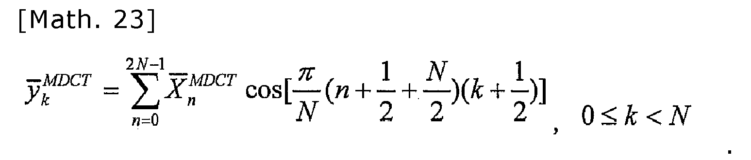
- The MDCT transform coefficients can be expressed in terms of DCT-IV as follows:
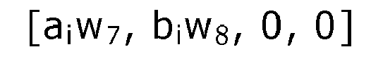
- As a result, the coefficients of the portion N/2 are all zero, and thus only the DCT-IV (aiw7 - (biw8)R) having the length of N/2 needs to be sent to the decoder. The length of the AAC-ELD coefficients is N. Therefore, by using the method according to the present embodiment, the bitrate is saved by half.
- The encoder according to the present embodiment having the block switching algorithm helps prepare the aliasing components of the frame i in order to perform aliasing cancellation with following frames coded in the AAC-ELD mode, when the coding mode is switched from the ACELP mode to the AAC-ELD mode. It reduces the computation complexity of the coding operation and reduces the bitrate compared to when using the AAC-ELD mode on the transition frame directly.
- In
Embodiment 6, a hybrid speech and audio encoder having a block switching algorithm is invented to code the transition frame where the ACELP mode is switched to the AAC-ELD mode. - The principle of
Embodiment 6 is the same asEmbodiment 5, but the encoder framework is different fromEmbodiment 5. - There are three coding modes in the encoder of
Embodiment 6, namely the AAC-ELD mode, the ACELP mode, and the TCX mode. The encoder frame work ofEmbodiment 6 is the same asEmbodiment 2. - In
Embodiment 7, a hybrid speech and audio decoder with block switching algorithms is invented to decode the transition frame where the ACELP mode is switched to the AAC-ELD mode. - In the present embodiment, block switching in the decoder from the ACELP mode to the AAC-ELD mode is performed according to the encoder in
Embodiment 5. When the coding mode is switched from the ACELP mode to the AAC-ELD mode, the following frames are switched back to the AAC-ELD overlapping and adding mode. Aliasing of the AAC-ELD are produced by using the aliasing portions of the inverse MDCT transform signal of the frame i, the non-aliasing portion of the ACELP synthesized signal of the frame i-1, and the reconstructed signal of the frame i-2 and the frame i-3.FIG. 9 illustrates the transition from the ACELP mode to the AAC-ELD mode in the decoder. - The decoder framework is the same as
Embodiment 3. The block switching method in the present embodiment is different fromEmbodiment 3.FIGS. 9 ,11 , and12 illustrate one example of the decoding processes. - According to
Embodiment 5, the received low band coefficients are MDCT transform coefficients DCT-IV (aiw7 - (biw8)R) in this transition frame i. Therefore, the corresponding inverse filter banks are IMDCT inEmbodiment 7. The aliasing outputs of the IMDCT are denoted as [aiw7 - (biw8)R, -(aiw7)R + biw8] having a length of N, shown as asub-frame 901 and asub-frame 902 inFIG. 9 . - The non-aliasing portions of ACELP synthesized signals from the previous frame i-1 are denoted as [ai-1, bi-1] having a length of N, shown as a
sub-frame 903 and asub-frame 904 inFIG. 9 . - The outputs of the previous two frames are denoted as [ai-2, bi-2] and [ai-3, bi-3], shown as
sub-frames FIG. 9 . - The aliasing portions of the inverse AAC-ELD are produced by using the sub-frames mentioned above. The purpose is to prepare the aliasing components for overlapping and adding with the following frames coded in the AAC-ELD mode, so that the coding mode can switch back to the normal AAC-ELD mode.
- One of the methods to generate the aliasing components introduced by inverse low delay filter banks is described in the following section.
FIGS. 11 and12 illustrate the detail processes of how to produce the aliasing elements of the AAC-ELD. - In
FIG. 11 , the decoded signal of a frame i-3 ai-3 is windowed to obtain ai-3w1. Folding is applied to obtain the reverse order (ai-3w1)R. - The second half of the decoded signal of the frame i-3 bi-3 is windowed to obtain bi-3w2.
- The first part of the non-aliasing portion of the ACELP synthesized signal ai-1 of the frame i-1 is windowed to obtain ai-1w5. Folding is applied to obtain the reverse order (ai-1w5)R.
- The second part of the non-aliasing portion of the ACELP synthesized signal is denoted as bi-1. Windowed is applied to bi-1 to obtain bi-1w6.
- By adding up the vectors (ai-3w1)R, bi-3w2, (ai-1w5)R, and bi-1w6, the aliasing components of inversed low delay filter banks coefficients yi are reconstructed as follows:
-

- By using the same analytical method, the rest of the components of the inversed transform coefficients yi is reconstructed.
FIG. 12 illustrates the detail of the processes of producing the aliasing portions of the AAC-ELD. -

- The aliasing portions of the AAC-ELD frame i are obtained, as shown in
FIG. 12 . -

- Decoder window [wR,8, wR,7, wR,6, wR,5, wR,4, wR,3, wR,2, wR,1] is applied to obtain the windowed aliasing portions:

-

- With the re-generated aliasing portions of the AAC-ELD, the aliasing cancellation with following AAC-ELD frames can be continued.
- The decoder according to the present embodiment having the block switching algorithm generates the aliasing components of the AAC-ELD mode using the MDCT coefficients, to facilitate the aliasing cancellation with the following frames coded in the AAC-ELD mode. According to an aspect of the present invention, it is possible to realize a seamless transition from the ACELP mode to the AAC-ELD mode in the low delay hybrid speech and audio codec having two coding modes.
- In
Embodiment 8, a hybrid speech and audio decoder having block switching algorithms is invented to decode the transition frame where the ACELP mode is switched to the AAC-ELD mode. - The principle of
Embodiment 8 is the same asEmbodiment 7. The decoder framework is different fromEmbodiment 7. - There are three decoding modes in
Embodiment 8, namely the AAC-ELD mode, the ACELP mode, and the TCX mode. The frame work ofEmbodiment 8 is the same asEmbodiment 4. - The decoder according to the present embodiment having the block switching algorithm generates the aliasing of the AAC-ELD mode to facilitate the aliasing cancellation with the following frames coded in the AAC-ELD mode. According to an aspect of the present invention, it is possible to realize a seamless transition from the ACELP mode to the AAC-ELD mode in the low delay hybrid speech and audio codec having three coding modes.
- In Embodiment 9, a speech and audio encoder having a block switching algorithm is invented to code the transition frame where the AAC-ELD mode is switched to the TCX mode.
- In order to cancel previous frame's aliasing introduced by the AAC-ELD mode in the decoder, the TCX frame size is extended. In the present embedment, the block switching algorithms concatenate the current frame with the previous frame to form an extended frame, whose length is longer than the normal frame size. This extended frame is coded in the TCX mode in the encoder.
- The encoder frame work is the same as
Embodiment 2. The block switching method in the present embodiment is different fromEmbodiment 2. The present embodiment is to code the transition frame where the AAC-ELD mode is switched to the TCX mode. -
FIG. 13 illustrates the coding process. The previous frame is coded in the AAC-ELD mode. In order to cancel the aliasing of the previous frame i-1 introduced by the AAC-ELD mode, the current frame i is concatenated with the previous frame i-1 to form a long frame. The processing frame size is 2N, where N is the frame size. The extended frame is coded in the TCX mode as shown inFIG. 13 . - The window size of the TCX mode is N. The overlapping length of the TCX mode is

Therefore, the extended frame contains three TCX windows as shown inFIG. 13 . - The encoder according to the present embodiment having the block switching algorithm facilitates the aliasing cancellation in the decoder when the coding mode is switched from the AAC-ELD mode to the TCX mode, and realizes a seamless combination of the AAC-ELD coding technology and the TCX coding technology in the low delay hybrid speech and audio codec having three coding modes.
- In Embodiment 10, a hybrid speech and audio decoder having a block switching algorithm is invented to decode the transition frame where the AAC-ELD mode is switched to the TCX mode.
- In present embodiment, the current frame is denoted as the frame i. In order to cancel the aliasing of the frame i-1 introduced by the AAC-ELD mode, the block switching algorithm generates the inverse aliasing components using the TCX synthesized signal of the frame i and the reconstructed signal of the frame i-2.
- The decoder framework is the same as
Embodiment 4. The block switching method in the present embodiment is different fromEmbodiment 4.FIG. 14 illustrates the block switching process. - According to Embodiment 9, the current transition frame is coded in the TCX mode using a processing frame size of 2N, where N is the frame size. According to the encoder in Embodiment 9, the TCX synthesis is used to synthesize in the decoder. The TCX synthesized signals are [ai-1 + aliasing, bi-1, ai, bi + aliasing] with a length of 2N. The non-aliasing portion bi-1, shown as a
sub-frame 1401 inFIG. 14 , is used for generation the aliasing component of asub-frame 1402. - The AAC-ELD synthesized signals of the previous frame i-1 is denoted as yi-1, and has a length of 4N. According to the AAC-ELD inverse transform described in the background section, the yi-1 is shown as follows:
-

- The AAC-ELD aliasing component -ai-3w3 + (bi-3w4)R + ai-1w7 - (bi-1w8)R, shown as the
sub-frame 1402, is cancelled by using the TCX synthesized signal bi-1 sub-frame 1401, and the reconstructed signal of i-2 outi-2 = [ai-3, bi-3], shown assub-frame 1403 and 1040. The transition frame is reconstructed. - The details of the aliasing cancellation processes in
FIG. 14 are the same as the description ofFIG. 8 . Thesub-frame 2301 inFIG. 23 is replaced by thenon-aliasing portion b i-1 1401. Thesub-frame 2302 that is the aliasing portion is replaced by 1402 inFIG. 14 . The non-aliasing portion, denoted as sub-frames 2304 and 2305 are replaced by outi-2 = [ai-3, bi-3], denoted as sub-frames 1403 and 1404 inFIG. 14 . The reconstructed signal of the transition frame i is [ai-1, bi-1]. - The decoder according to the present embodiment having the block switching algorithm cancels the aliasing of the frame i-1 introduced by the AAC-ELD mode. This enables a seamless transition from the AAC-ELD mode to the TCX mode in the low delay hybrid speech and audio codec.
- In Embodiment 11, a hybrid speech and audio encoder having a block switching algorithm is invented to code the transition frame where the TCX mode is switched to the AAC-ELD mode.
- The current transition frame is denoted as the frame i and it is coded in the AAC-ELD mode. The previous frame is coded in the TCX mode. In order to cancel the aliasing of the frame i introduced by the AAC-ELD low delay filter banks, the block switching algorithm codes the current frame together with three previous frames in the AAC-ELD mode.
- The encoder framework is the same as
Embodiment 2. The block switching method in the present embodiment is different fromEmbodiment 2. -
FIG. 15 illustrates the coding process for the transition frame where the TCX mode is switched to the AAC-ELD mode in the encoder. According to Embodiment 9, the length of overlapping, in the TCX mode, is
where N is the frame size. For a frame coded in the normal TCX mode, two TCX windows are applied as shown inFIG. 15 . - For the current transition frame, the AAC-ELD mode is directly applied as shown in
FIG. 15 . - The encoder in Embodiment 11 facilitates the aliasing cancelling performed in the decoder when the TCX mode is switched to the AAC-ELD mode. The block switching algorithm in the present embodiment realizes the seamless combination of the AAC-ELD coding technology and the TCX coding technology in the low delay hybrid speech and audio codec.
- In Embodiment 12, a hybrid speech and audio decoder having a block switching algorithm is invented to decode the transition frame where the TCX mode is switched to the AAC-ELD mode.
- The block switching algorithm in the present embodiment generates the aliasing of the AAC-ELD using the TCX synthesized signals and the reconstructed signal of the frame i-2, and cancels the aliasing of the AAC-ELD for the block switching purpose.
-
FIG. 16 illustrates the corresponding decoding processes for the transition frame where the TCX mode is switched to the AAC-ELD mode. According to the encoder described in Embodiment 11, the previous frame is coded in the TCX mode. After the TCX synthesis, the TCX synthesized signals are [bi-2 + aliasing, ai-1, bi-1 + aliasing], and have a length of
ai-1 is shown as asub-frame 1601 inFIG. 16 . - For the current frame i, after the inverse low delay filter banks, the inverse transform signal is denoted as yi and has a length of 4N as shown below.
-
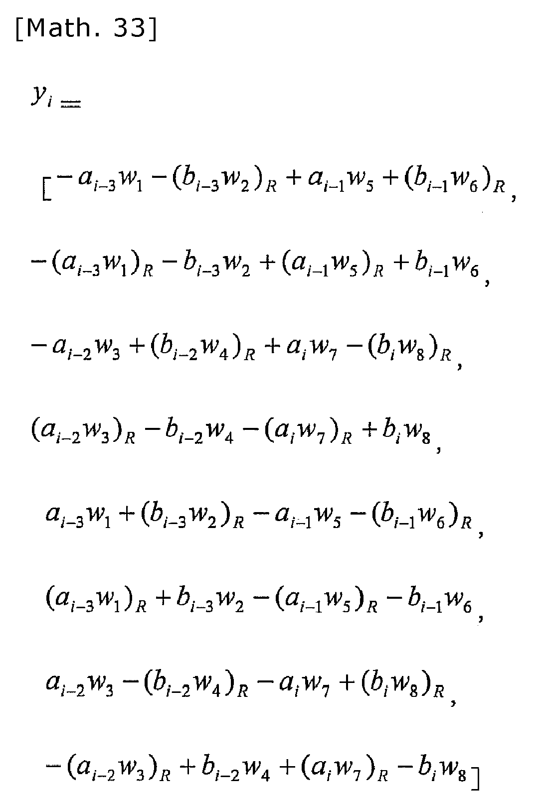
- The aliasing portion - (ai-3w1)R - bi-3w2 + (ai-1w5)R + bi-1w6, shown as a
sub-frame 1602, is cancelled by the TCX synthesized signal ai-1 and the frame i-2 outi-2=[ai-3, bi-3] of the reconstructed signal shown assub-frames -
FIG. 17 illustrates one example of aliasing cancellation. The reconstructed signal of the frame i-2 ai-3 is windowed to obtain ai-3w1 as shown inFIG. 17 . The reverse vector of ai-3w1 is denoted as (ai-3w1)R. - The second half of the outi-2 is windowed to obtain bi-3w2.
- The TCX synthesized signal ai-1 is windowed to obtain ai-1w5. The reverse order of ai-1w5 is (ai-1w5)R.
- By adding and inverse windowing the re-produced aliasing components bi-1w6, a sub-frame 1701 bi-1 is reconstructed. To obtain the current transition frame, the
sub-frame 1701 is concatenated with thesub-frame 1601 as shown inFIG. 17 . - Due to the quantization error, the concatenation border is not smooth. An adapted border smoothing algorithm is invented to eliminate the artefacts.
FIG. 24 is illustrates the sub-frame border smoothing processes. - The sub-frame 1701 bi-1 is windowed by the TCX window shape. Folding and unfolding processes are applied to generate the MDCT-TCX aliasing components. The outcome is overlapped with the aliasing portions of the
sub-frame 1605, which are originally from the MDCT-TCX inverse transform, to obtain asub-frame 2401. The border between thesub-frames - The decoder according to the present embodiment having the block switching algorithm cancels the aliasing of the frame i introduced by the AAC-ELD mode. This enables a seamless transition from the TCX mode to the AAC-ELD mode.
- In Embodiment 13, a coding method for coding the transient signal in the low delay hybrid speech and audio codec is invented.
- In the AAC-ELD codec, only the long window shape is used. It reduces the coding performance of the transient signal in which the energy has an abrupt change. To handle the transient signal, the short window is preferable. A transient signal coding algorithm is invented in the present embodiment. The current frame i having a transient signal is concatenated with the previous frame to form an extended frame having a longer frame size. Multiple short windows and an MDCT filter bank are used to code this processed frame.
- The encoder framework is the same as
Embodiments FIG. 18 illustrates the coding processed in the encoder. The previous frame i-1 is coded together with three previous frames in the AAC-ELD mode. The frame i is concatenated with the previous frame as shown inFIG. 18 . The length of the long extended transient frame is
Six short windows having a length of
are applied on the extended frame. The shape of the short window can be any symmetric window used by the MDCT filter banks. The MDCT filer banks are applied to short windowed signals. - The encoder according to the present embodiment provides the transient signal handling algorithm to improve the sound quality of the low delay hybrid codec which uses the AAC-ELD coding technology.
- In Embodiment 14, a hybrid speech and audio decoder for decoding the transient signal is invented.
- The transient frame i is coded by the short window MDCT as explained in Embodiment 13. In order to cancel the aliasing of the frame i-1, which is introduced by the AAC-ELD mode, the transient decoding method in the present embodiment uses the inverse MDCT transform signal of the frame i and the reconstructed signal of the frame i-3 to generate the inverse aliasing of the AAC-ELD mode.
- The decoding processes of the transient frame are illustrated in
FIG. 19 . According to the coding processes described in Embodiment 13, after the IMDCT and overlapping and adding are performed, asignal 1902 is [ai-1 + aliasing, bi-1, ai, bi + aliasing] with a length of
- The non-aliasing portion bi-1 from MDCT, shown as 1902 in
FIG. 19 , the AAC-ELD inversetransform signal y i-1 1904 of the frame i-1 and the reconstructed signal outi-2 = [ai-3, bi-3] 1905 of the frame i-3 are sent to ablock 1901 inFIG. 19 for reconstructing the signal [ai-1, bi-1]. Therefore, the output of the frame i is [ai-1, bi-1]. - The processes of the
block 1901 inFIG. 19 are the same asFIG. 8 . Thesub-frame 2301 inFIG. 23 is replaced by thenon-aliasing portion 1902. Thesub-frame 2302 that is the aliasing portion is replaced by 1904 inFIG. 19 . The non-aliasing portion denoted as thesub-frames FIG. 19 . - The invented decoder provides a transient signal handling method to improve the coding performance of the transient signal. As a result, the sound quality of the low delay hybrid codec which employs the AAC-ELD coding technology is improved.
- The present invention relates, in general, to hybrid audio coding systems, and is more particularly related to hybrid coding systems which support audio coding and speech coding in low bitrate. The hybrid coding system combines the transform coding and the time domain coding. It can be used in broadcasting systems, mobile
- TVs, mobile phones communication, and teleconferences.
Claims (18)
- A hybrid audio decoder which decodes a coded stream while switching between a speech coding mode in which linear prediction coefficients are used and an audio coding mode in which a low delay orthogonal transform is used, the hybrid audio decoder comprising:a low delay transform decoder which decodes a coded signal in the audio coding mode using an inverse low delay filter bank, to generate a synthesized signal;an audio decoder which decodes, in the speech coding mode, a coded signal including the linear prediction coefficients, to generate an audio synthesized signal; anda block switcher which decodes a first transition frame using a signal of a previous frame preceding a current frame to be decoded, and combines a signal of the decoded first transition frame and the audio synthesized signal of the current frame generated by the audio decoder, to reconstruct a time domain signal of an input signal, the first transition frame being a frame where the audio coding mode in which the low delay orthogonal transform is used is switched to the speech coding mode in which the linear prediction coefficients are used.
- The hybrid audio decoder according to Claim 1,
wherein the block switcher decodes the first transition frame using: the audio synthesized signal of the current frame; an inverse transform signal of the previous frame from a plurality of inverse low delay filter banks including the inverse low delay filter bank; and a reconstructed signal of the previous frame. - The hybrid audio decoder according to Claim 2,
wherein the audio decoder includes an algebraic code-excited linear prediction decoder which decodes the linear prediction coefficients and algebraic code-excited coefficients to generate the audio synthesized signal, and
the block switcher decodes the first transition frame using: an algebraic code-excited linear prediction synthesized signal of the current frame; the inverse transform signal of the previous frame from the plurality of inverse low delay filter banks; and the reconstructed signal of the previous frame, when the first transition frame is a frame where the audio coding mode in which the low delay orthogonal transform is used is switched to the speech coding mode in which the algebraic code-excited linear prediction coefficients are used. - The hybrid audio decoder according to Claim 3,
wherein the audio decoder further includes a transform coded excitation decoder which decodes the linear prediction coefficients to generate an excitation synthesized signal by an orthogonal transform,
and
the block switcher decodes the first transition frame using: a transform coded excitation synthesized signal of the current frame; the inverse transform signal of the previous frame from the inverse low delay filter bank; and the reconstructed signal of the previous frame, when the first transition frame is a frame where the audio coding mode in which the low delay orthogonal transform is used is switched to the speech coding mode in which transform coded excitation decoding is performed. - The hybrid audio decoder according to Claim 3,
wherein the block switcher decodes a second transition frame using: inverse transform signals of a plurality of current frames to be decoded from an inverse modified discrete cosine transform filter bank; an algebraic code-excited linear prediction synthesized signal of a previous frame; and a reconstructed signal of the previous frame, when the speech coding mode is the speech coding mode in which the algebraic code-excited linear prediction coefficients are used, the second transition frame being a frame where the speech coding mode is switched to the audio coding mode. - The hybrid audio decoder according to Claim 4,
wherein the block switcher decodes a second transition frame using: inverse transform signals of a plurality of current frames to be decoded from the inverse low delay filter bank; a transform coded excitation synthesized signal of the previous frame; and the reconstructed signal of the previous frame, when the speech coding mode is the speech coding mode in which transform coded excitation coefficients are used, the second transition frame being a frame where the speech coding mode is switched to the audio coding mode. - The hybrid audio decoder according to Claim 1,
wherein the low delay transform decoder decodes the current frame in the audio coding mode in which a plurality of modified discrete cosine transform filter banks are used instead of the inverse low delay filter bank. - The hybrid audio decoder according to Claim 7,
wherein the low delay transform decoder applies an inverse modified discrete cosine transform filter bank to the extended frame which has been short windowed, and decodes a time signal of the extended frame using: inverse transform signals of a plurality of current frames to be decoded from the inverse modified discrete cosine transform filter bank; an inverse transform signal of the previous frame; and a reconstructed signal of the previous frame, the inverse transform signal of the previous frame being included in the extended frame. - A hybrid audio encoder which codes an input signal while switching between a speech coding mode in which linear prediction coefficients are used and an audio coding mode in which a low delay orthogonal transform is used, the hybrid audio encoder comprising:a signal classifier which classifies the input signal according to a characteristic of the input signal, and according to a result of the classification, switches between the speech coding mode and the audio coding mode as a coding mode for coding the input signal;a low delay transform encoder which codes the input signal of a plurality of current frames to be coded in the audio coding mode using a low delay filter bank to generate a coded signal using a coded low delay orthogonal transform;a linear prediction encoder which calculates a plurality of linear prediction coefficients of the input signal of the current frames in the speech coding mode to generate a coded signal including the plurality of linear prediction coefficients; anda block switcher which forms an extended frame by concatenating a first transition frame and the current frames and codes the extended frame, the first transition frame being: a frame where the signal classifier has switched the coding mode from the audio coding mode in which the low delay orthogonal transform is used to the speech coding mode in which the linear prediction coefficients are used; and a previous frame preceding the current frames.
- The hybrid audio encoder according to Claim 9,
wherein the linear prediction encoder includes:a transform coded excitation encoder which codes a residual of the plurality of linear prediction coefficients using a modified discrete cosine transform filter bank, to generate a coded signal including a plurality of transform coded excitation coefficients and the plurality of linear prediction coefficients; andan algebraic code-excited linear prediction encoder which generates a coded signal including the plurality of linear prediction coefficients and a plurality of algebraic code-excited coefficients. - The hybrid audio encoder according to Claim 9,
wherein the block switcher transforms a plurality of extended frames including the extended frame using a modified discrete cosine transform filter bank to code a second transition frame which is a frame where the speech coding mode is switched to the audio coding mode. - The hybrid audio encoder according to Claim 9,
wherein the block switcher forms the extended frame by concatenating the current frames and the previous frame preceding the current frames, short windows the extended frame, and codes the short windowed extended frame using a transform by a modified discrete cosine transform filter bank. - The block switcher included in the hybrid audio decoder according to Claim 3 or Claim 4, the block switcher comprising:a. a processing unit configured to process either the algebraic code-excited linear prediction synthesized signal or the transform coded excitation synthesized signal of the current frame by windowing and order arranging, to obtain a first signal;b. a processing unit configured to process the reconstructed signal of the previous frame by windowing and order arranging, to obtain a second signal;c. a processing unit configured to add the first signal and the second signal to the inverse transform signal of a plurality of previous frames including the previous frame from the inverse low delay filter bank, to obtain a third signal;d. a processing unit configured to process the third signal by windowing and order arranging, to obtain a fourth signal; ande. a processing unit configured to concatenate the fourth signal with the algebraic code-excited linear prediction synthesized signal or the transform coded excitation synthesized signal of the current frame to obtain a reconstructed signal.
- The block switcher included in the hybrid audio decoder according to Claim 7 or Claim 8, the block switcher comprising:a. a processing unit configured to process the reconstructed signal which is three frames before a current frame to be decoded by windowing and order arranging, to obtain a first signal;b. a processing unit configured to process either an algebraic code-excited linear prediction synthesized signal or a transform coded excitation synthesized signal of the previous frame by windowing and order arranging, to obtain a second signal;c. a processing unit configured to add the first signal and the second signal to obtain a third signal; andd. a processing unit configured to process the third signal by windowing and order arranging, to obtain a portion of an inverse low delay orthogonal transform signal of the current frame.
- The block switcher included in the hybrid audio decoder according to Claim 7 or Claim 8, the block switcher comprising:a. a processing unit configured to process the reconstructed signal which is two frames before a current frame to be decoded by windowing and order arranging, to obtain a first signal;b. a processing unit configured to add the first signal and the reconstructed signal to a plurality of inverse transform signals of the current frame from the inverse low delay filter bank, to obtain a third signal; andc. a processing unit configured to process the third signal by windowing and order arranging, to obtain a portion of an inverse low delay transform signal of the current block.
- The block switcher included in the hybrid audio decoder according to Claim 4, the block switcher comprising:a. a processing unit configured to process a transform coded excitation synthesized signal of a current frame to be decoded by windowing and order arranging, to obtain a first signal;b. a processing unit configured to process the reconstructed signal of a previous frame by windowing and order arranging, to obtain a second signal;c. a processing unit configured to add the first signal and the second signal to the inverse transform signal of a plurality of previous frames including the previous frame from the inverse low delay filter bank, to obtain a third signal;d. a processing unit configured to process the third signal by windowing and order arranging, to obtain a fourth signal; ande. a processing unit configured to concatenate the fourth signal with the transform coded excitation synthesized signal of the current frame to obtain a reconstructed signal.
- The block switcher included in the hybrid audio decoder according to Claim 6, the block switcher comprising:a. a processing unit configured to process the transform coded excitation synthesized signal of the previous frame by windowing and order arranging, to obtain a first signal;b. a processing unit configured to process the reconstructed signal of a previous frame by windowing and order arranging, to obtain a second signal;c. a processing unit configured to add the first signal and the second signal to the inverse transform signal of the current frames from the inverse low delay filter bank, to obtain a third signal;d. a processing unit configured to process the third signal by windowing and order arranging, to obtain a fourth signal; ande. a processing unit configured to concatenate the fourth signal with the transform coded excitation synthesized signal of the previous frame to obtain a reconstructed signal.
- The block switcher included in the hybrid audio decoder according to Claim 8, the block switcher comprising:a. a processing unit configured to process a reconstructed signal of a plurality of current frames to be decoded from the inverse modified discrete cosine transform filter bank by windowing and order arranging, to obtain a first signal;b. a processing unit configured to process the reconstructed signal of the previous frame by windowing and order arranging, to obtain a second signal;c. a processing unit configured to add the first signal and the second signal to inverse transform signals of a plurality of previous frames from the inverse low delay filter bank, to obtain a third signal;d. a processing unit configured to process the third signal by windowing and order arranging, to obtain a fourth signal; ande. a processing unit configured to concatenate the fourth signal with the reconstructed signal of the current frames from the inverse modified discrete cosine transform filter bank, to obtain a reconstructed signal.
Applications Claiming Priority (2)
| Application Number | Priority Date | Filing Date | Title |
|---|---|---|---|
| JP2010134848 | 2010-06-14 | ||
| PCT/JP2011/003352 WO2011158485A2 (en) | 2010-06-14 | 2011-06-14 | Audio hybrid encoding device, and audio hybrid decoding device |
Publications (2)
| Publication Number | Publication Date |
|---|---|
| EP2581902A1 true EP2581902A1 (en) | 2013-04-17 |
| EP2581902A4 EP2581902A4 (en) | 2015-04-08 |
Family
ID=45348685
Family Applications (1)
| Application Number | Title | Priority Date | Filing Date |
|---|---|---|---|
| EP11795393.5A Withdrawn EP2581902A4 (en) | 2010-06-14 | 2011-06-14 | Audio hybrid encoding device, and audio hybrid decoding device |
Country Status (6)
| Country | Link |
|---|---|
| US (1) | US9275650B2 (en) |
| EP (1) | EP2581902A4 (en) |
| JP (1) | JP5882895B2 (en) |
| KR (1) | KR101790373B1 (en) |
| CN (1) | CN102934161B (en) |
| WO (1) | WO2011158485A2 (en) |
Cited By (1)
| Publication number | Priority date | Publication date | Assignee | Title |
|---|---|---|---|---|
| EP2863386A1 (en) * | 2013-10-18 | 2015-04-22 | Fraunhofer-Gesellschaft zur Förderung der angewandten Forschung e.V. | Audio decoder, apparatus for generating encoded audio output data and methods permitting initializing a decoder |
Families Citing this family (12)
| Publication number | Priority date | Publication date | Assignee | Title |
|---|---|---|---|---|
| AU2009267518B2 (en) * | 2008-07-11 | 2012-08-16 | Fraunhofer-Gesellschaft Zur Foerderung Der Angewandten Forschung E.V. | Apparatus and method for encoding/decoding an audio signal using an aliasing switch scheme |
| PL4120248T3 (en) * | 2010-07-08 | 2024-05-13 | Fraunhofer-Gesellschaft zur Förderung der angewandten Forschung e.V. | Decoder using forward aliasing cancellation |
| US20140058737A1 (en) * | 2011-10-28 | 2014-02-27 | Panasonic Corporation | Hybrid sound signal decoder, hybrid sound signal encoder, sound signal decoding method, and sound signal encoding method |
| EP2849180B1 (en) * | 2012-05-11 | 2020-01-01 | Panasonic Corporation | Hybrid audio signal encoder, hybrid audio signal decoder, method for encoding audio signal, and method for decoding audio signal |
| CN103714821A (en) | 2012-09-28 | 2014-04-09 | 杜比实验室特许公司 | Mixed domain data packet loss concealment based on position |
| CN110265047B (en) | 2013-04-05 | 2021-05-18 | 杜比国际公司 | Audio signal decoding method, audio signal decoder, audio signal medium, and audio signal encoding method |
| BR112015019176B1 (en) | 2013-04-05 | 2021-02-09 | Dolby Laboratories Licensing Corporation | method and apparatus for expanding an audio signal, method and apparatus for compressing an audio signal, and computer-readable media |
| FR3013496A1 (en) * | 2013-11-15 | 2015-05-22 | Orange | TRANSITION FROM TRANSFORMED CODING / DECODING TO PREDICTIVE CODING / DECODING |
| CN105096958B (en) * | 2014-04-29 | 2017-04-12 | 华为技术有限公司 | audio coding method and related device |
| CN104143335B (en) | 2014-07-28 | 2017-02-01 | 华为技术有限公司 | audio coding method and related device |
| WO2017050398A1 (en) * | 2015-09-25 | 2017-03-30 | Fraunhofer-Gesellschaft zur Förderung der angewandten Forschung e.V. | Encoder, decoder and methods for signal-adaptive switching of the overlap ratio in audio transform coding |
| US10499229B2 (en) * | 2016-01-24 | 2019-12-03 | Qualcomm Incorporated | Enhanced fallback to in-band mode for emergency calling |
Family Cites Families (20)
| Publication number | Priority date | Publication date | Assignee | Title |
|---|---|---|---|---|
| US7394833B2 (en) | 2003-02-11 | 2008-07-01 | Nokia Corporation | Method and apparatus for reducing synchronization delay in packet switched voice terminals using speech decoder modification |
| PL1618763T3 (en) | 2003-04-17 | 2007-07-31 | Koninl Philips Electronics Nv | Audio signal synthesis |
| ATE359687T1 (en) | 2003-04-17 | 2007-05-15 | Koninkl Philips Electronics Nv | AUDIO SIGNAL GENERATION |
| US7596486B2 (en) | 2004-05-19 | 2009-09-29 | Nokia Corporation | Encoding an audio signal using different audio coder modes |
| US20060294312A1 (en) | 2004-05-27 | 2006-12-28 | Silverbrook Research Pty Ltd | Generation sequences |
| EP1841072B1 (en) * | 2006-03-30 | 2016-06-01 | Unify GmbH & Co. KG | Method and apparatus for decoding layer encoded data |
| CN101231850B (en) * | 2007-01-23 | 2012-02-29 | 华为技术有限公司 | Encoding/decoding device and method |
| EP2015293A1 (en) | 2007-06-14 | 2009-01-14 | Deutsche Thomson OHG | Method and apparatus for encoding and decoding an audio signal using adaptively switched temporal resolution in the spectral domain |
| KR101405971B1 (en) * | 2007-07-02 | 2014-06-12 | 엘지전자 주식회사 | broadcasting receiver and method of processing broadcast signal |
| KR101490246B1 (en) * | 2007-07-02 | 2015-02-05 | 엘지전자 주식회사 | broadcasting receiver and method of processing broadcast signal |
| CN101971251B (en) * | 2008-03-14 | 2012-08-08 | 杜比实验室特许公司 | Multimode coding method and device of speech-like and non-speech-like signals |
| CA2729752C (en) * | 2008-07-10 | 2018-06-05 | Voiceage Corporation | Multi-reference lpc filter quantization and inverse quantization device and method |
| ES2558229T3 (en) | 2008-07-11 | 2016-02-02 | Fraunhofer-Gesellschaft zur Förderung der angewandten Forschung e.V. | Audio encoder and decoder for encoding frames of sampled audio signals |
| EP2144230A1 (en) | 2008-07-11 | 2010-01-13 | Fraunhofer-Gesellschaft zur Förderung der angewandten Forschung e.V. | Low bitrate audio encoding/decoding scheme having cascaded switches |
| PL3002750T3 (en) | 2008-07-11 | 2018-06-29 | Fraunhofer-Gesellschaft zur Förderung der angewandten Forschung e.V. | Audio encoder and decoder for encoding and decoding audio samples |
| MX2011000375A (en) | 2008-07-11 | 2011-05-19 | Fraunhofer Ges Forschung | Audio encoder and decoder for encoding and decoding frames of sampled audio signal. |
| AU2009267518B2 (en) | 2008-07-11 | 2012-08-16 | Fraunhofer-Gesellschaft Zur Foerderung Der Angewandten Forschung E.V. | Apparatus and method for encoding/decoding an audio signal using an aliasing switch scheme |
| EP3640941A1 (en) * | 2008-10-08 | 2020-04-22 | Fraunhofer Gesellschaft zur Förderung der Angewand | Multi-resolution switched audio encoding/decoding scheme |
| WO2011013983A2 (en) | 2009-07-27 | 2011-02-03 | Lg Electronics Inc. | A method and an apparatus for processing an audio signal |
| CN101661749A (en) | 2009-09-23 | 2010-03-03 | 清华大学 | Speech and music bi-mode switching encoding/decoding method |
-
2011
- 2011-06-14 WO PCT/JP2011/003352 patent/WO2011158485A2/en active Application Filing
- 2011-06-14 EP EP11795393.5A patent/EP2581902A4/en not_active Withdrawn
- 2011-06-14 US US13/703,044 patent/US9275650B2/en active Active
- 2011-06-14 KR KR1020127031469A patent/KR101790373B1/en active IP Right Grant
- 2011-06-14 CN CN201180028085.9A patent/CN102934161B/en active Active
- 2011-06-14 JP JP2012520286A patent/JP5882895B2/en active Active
Cited By (14)
| Publication number | Priority date | Publication date | Assignee | Title |
|---|---|---|---|---|
| EP2863386A1 (en) * | 2013-10-18 | 2015-04-22 | Fraunhofer-Gesellschaft zur Förderung der angewandten Forschung e.V. | Audio decoder, apparatus for generating encoded audio output data and methods permitting initializing a decoder |
| WO2015055683A1 (en) * | 2013-10-18 | 2015-04-23 | Fraunhofer-Gesellschaft zur Förderung der angewandten Forschung e.V. | Audio decoder, apparatus for generating encoded audio output data and methods permitting initializing a decoder |
| CN105745704A (en) * | 2013-10-18 | 2016-07-06 | 弗朗霍夫应用科学研究促进协会 | Audio decoder, apparatus for generating encoded audio output data and methods permitting initializing a decoder |
| TWI579832B (en) * | 2013-10-18 | 2017-04-21 | 弗勞恩霍夫爾協會 | Audio decoder, apparatus for generating encoded audio output data and methods permitting initializing a decoder |
| US9928845B2 (en) | 2013-10-18 | 2018-03-27 | Fraunhofer-Gesellschaft Zur Foerderung Der Angewandten Forschung E.V. | Audio decoder, apparatus for generating encoded audio output data and methods permitting initializing a decoder |
| RU2651190C2 (en) * | 2013-10-18 | 2018-04-18 | Фраунхофер-Гезелльшафт Цур Фердерунг Дер Ангевандтен Форшунг Е.Ф. | Audio decoder, device for forming output encoded audio data and methods allowing the initialization of decoder |
| US10229694B2 (en) | 2013-10-18 | 2019-03-12 | Fraunhofer-Gesellschaft Zur Foerderung Der Angewandten Forschung E.V. | Audio decoder, apparatus for generating encoded audio output data and methods permitting initializing a decoder |
| CN105745704B (en) * | 2013-10-18 | 2019-08-23 | 弗朗霍夫应用科学研究促进协会 | For coding and decoding the device and method of audio data |
| US10614824B2 (en) | 2013-10-18 | 2020-04-07 | Fraunhofer-Gesellschaft Zur Foerderung Der Angewandten Forschung E.V. | Audio decoder, apparatus for generating encoded audio output data and methods permitting initializing a decoder |
| US11423919B2 (en) | 2013-10-18 | 2022-08-23 | Fraunhofer-Gesellschaft Zur Foerderung Der Angewandten Forschung E.V. | Audio decoder, apparatus for generating encoded audio output data and methods permitting initializing a decoder |
| US11670314B2 (en) | 2013-10-18 | 2023-06-06 | Fraunhofer-Gesellschaft Zur Foerderung Der Angewandten Forschung E.V. | Audio decoder, apparatus for generating encoded audio output data and methods permitting initializing a decoder |
| US12080309B2 (en) | 2013-10-18 | 2024-09-03 | Fraunhofer-Gesellschaft Zur Foerderung Der Angewandten Forschung E.V. | Audio decoder, apparatus for generating encoded audio output data and methods permitting initializing a decoder |
| US12094479B2 (en) | 2013-10-18 | 2024-09-17 | Fraunhofer-Gesellschaft Zur Foerderung Der Angewandten Forschung E.V. | Audio decoder, apparatus for generating encoded audio output data and methods permitting initializing a decoder |
| US12094478B2 (en) | 2013-10-18 | 2024-09-17 | Fraunhofer-Gesellschaft Zur Foerderung Der Angewandten Forschung E.V. | Audio decoder, apparatus for generating encoded audio output data and methods permitting initializing a decoder |
Also Published As
| Publication number | Publication date |
|---|---|
| WO2011158485A2 (en) | 2011-12-22 |
| KR101790373B1 (en) | 2017-10-25 |
| KR20130028751A (en) | 2013-03-19 |
| JPWO2011158485A1 (en) | 2013-08-19 |
| JP5882895B2 (en) | 2016-03-09 |
| EP2581902A4 (en) | 2015-04-08 |
| CN102934161A (en) | 2013-02-13 |
| CN102934161B (en) | 2015-08-26 |
| US20130090929A1 (en) | 2013-04-11 |
| US9275650B2 (en) | 2016-03-01 |
Similar Documents
| Publication | Publication Date | Title |
|---|---|---|
| US9275650B2 (en) | Hybrid audio encoder and hybrid audio decoder which perform coding or decoding while switching between different codecs | |
| AU2006252962B2 (en) | Audio CODEC post-filter | |
| RU2485606C2 (en) | Low bitrate audio encoding/decoding scheme using cascaded switches | |
| KR101508819B1 (en) | Multi-mode audio codec and celp coding adapted therefore | |
| KR101366124B1 (en) | Device for perceptual weighting in audio encoding/decoding | |
| KR101699898B1 (en) | Apparatus and method for processing a decoded audio signal in a spectral domain | |
| RU2591011C2 (en) | Audio signal encoder, audio signal decoder, method for encoding or decoding audio signal using aliasing-cancellation | |
| EP2849180B1 (en) | Hybrid audio signal encoder, hybrid audio signal decoder, method for encoding audio signal, and method for decoding audio signal | |
| JP6110314B2 (en) | Apparatus and method for encoding and decoding audio signals using aligned look-ahead portions | |
| US20130030798A1 (en) | Method and apparatus for audio coding and decoding | |
| MX2011000366A (en) | Audio encoder and decoder for encoding and decoding audio samples. | |
| KR20120063543A (en) | Multi-mode audio signal decoder, multi-mode audio signal encoder, methods and computer program using a linear-prediction-coding based noise shaping | |
| WO2013061584A1 (en) | Hybrid sound-signal decoder, hybrid sound-signal encoder, sound-signal decoding method, and sound-signal encoding method | |
| Ragot et al. | A 8-32 kbit/s scalable wideband speech and audio coding candidate for ITU-T G729EV standardization | |
| JP3598111B2 (en) | Broadband audio restoration device | |
| JP3560964B2 (en) | Broadband audio restoration apparatus, wideband audio restoration method, audio transmission system, and audio transmission method | |
| JP3636327B2 (en) | Wideband voice restoration method and wideband voice restoration apparatus | |
| JP3748083B2 (en) | Broadband speech restoration method and broadband speech restoration apparatus | |
| JP3748082B2 (en) | Broadband speech restoration method and broadband speech restoration apparatus | |
| JP3598112B2 (en) | Broadband audio restoration method and wideband audio restoration apparatus | |
| JP3773509B2 (en) | Broadband speech restoration apparatus and broadband speech restoration method | |
| JP2006065362A (en) | Wideband voice decoding apparatus | |
| JP2005092246A (en) | Method and device for broadband voice restoration | |
| JP2005284315A (en) | Method and device for wide-band speech restoration | |
| JP2005284316A (en) | Method and device for wide-band speech restoration |
Legal Events
| Date | Code | Title | Description |
|---|---|---|---|
| PUAI | Public reference made under article 153(3) epc to a published international application that has entered the european phase |
Free format text: ORIGINAL CODE: 0009012 |
|
| 17P | Request for examination filed |
Effective date: 20121210 |
|
| AK | Designated contracting states |
Kind code of ref document: A1 Designated state(s): AL AT BE BG CH CY CZ DE DK EE ES FI FR GB GR HR HU IE IS IT LI LT LU LV MC MK MT NL NO PL PT RO RS SE SI SK SM TR |
|
| RIN1 | Information on inventor provided before grant (corrected) |
Inventor name: NORIMATSU, TAKESHI Inventor name: ZHONG, HAISHAN Inventor name: ZHOU, HUAN Inventor name: CHONG, KOK SENG Inventor name: ISHIKAWA, TOMOKAZU |
|
| DAX | Request for extension of the european patent (deleted) | ||
| RA4 | Supplementary search report drawn up and despatched (corrected) |
Effective date: 20150306 |
|
| RIC1 | Information provided on ipc code assigned before grant |
Ipc: G10L 19/02 20130101AFI20150302BHEP Ipc: G10L 19/20 20130101ALI20150302BHEP Ipc: G10L 19/107 20130101ALI20150302BHEP Ipc: G10L 19/022 20130101ALN20150302BHEP |
|
| STAA | Information on the status of an ep patent application or granted ep patent |
Free format text: STATUS: THE APPLICATION HAS BEEN WITHDRAWN |
|
| 18W | Application withdrawn |
Effective date: 20150706 |