EP2581815A2 - Akustische Berührungsvorrichtung - Google Patents
Akustische Berührungsvorrichtung Download PDFInfo
- Publication number
- EP2581815A2 EP2581815A2 EP12188142.9A EP12188142A EP2581815A2 EP 2581815 A2 EP2581815 A2 EP 2581815A2 EP 12188142 A EP12188142 A EP 12188142A EP 2581815 A2 EP2581815 A2 EP 2581815A2
- Authority
- EP
- European Patent Office
- Prior art keywords
- window
- lens
- surface acoustic
- substrate
- acoustic
- Prior art date
- Legal status (The legal status is an assumption and is not a legal conclusion. Google has not performed a legal analysis and makes no representation as to the accuracy of the status listed.)
- Granted
Links
Images


Classifications
-
- G—PHYSICS
- G06—COMPUTING OR CALCULATING; COUNTING
- G06F—ELECTRIC DIGITAL DATA PROCESSING
- G06F3/00—Input arrangements for transferring data to be processed into a form capable of being handled by the computer; Output arrangements for transferring data from processing unit to output unit, e.g. interface arrangements
- G06F3/01—Input arrangements or combined input and output arrangements for interaction between user and computer
- G06F3/03—Arrangements for converting the position or the displacement of a member into a coded form
- G06F3/041—Digitisers, e.g. for touch screens or touch pads, characterised by the transducing means
- G06F3/043—Digitisers, e.g. for touch screens or touch pads, characterised by the transducing means using propagating acoustic waves
- G06F3/0436—Digitisers, e.g. for touch screens or touch pads, characterised by the transducing means using propagating acoustic waves in which generating transducers and detecting transducers are attached to a single acoustic waves transmission substrate
-
- G—PHYSICS
- G06—COMPUTING OR CALCULATING; COUNTING
- G06F—ELECTRIC DIGITAL DATA PROCESSING
- G06F1/00—Details not covered by groups G06F3/00 - G06F13/00 and G06F21/00
- G06F1/16—Constructional details or arrangements
- G06F1/1613—Constructional details or arrangements for portable computers
- G06F1/1633—Constructional details or arrangements of portable computers not specific to the type of enclosures covered by groups G06F1/1615 - G06F1/1626
- G06F1/1684—Constructional details or arrangements related to integrated I/O peripherals not covered by groups G06F1/1635 - G06F1/1675
- G06F1/1686—Constructional details or arrangements related to integrated I/O peripherals not covered by groups G06F1/1635 - G06F1/1675 the I/O peripheral being an integrated camera
Definitions
- This invention generally relates to acoustic touch sensors and, more particularly, to surface acoustic wave (SAW) touchscreens.
- SAW surface acoustic wave
- Touch sensor systems such as touchscreens or touch monitors, can act as input devices for interactive computer systems used for various applications, for example, information kiosks, order entry systems, video displays, mobile communications, etc. Such systems may be integrated into a computing device, thus providing interactive touch capable computing devices, including computers, electronic book readers, or mobile communications devices.
- touch sensor systems enable the determination of a position on the surface of a substrate via a user's touch of the surface.
- the touch substrate is typically made of some form of glass which overlies a computer or computing device display, like a liquid crystal display (LCD), an organic light emitting diode (OLED) display, plasma display, etc.
- the touch sensor system is operatively connected to the device display so as to enable the determination of a position on the device display and, moreover, of the appropriate control action of a user interface such as shown on the display.
- Touch sensor systems may be implemented using different technologies.
- Acoustic touch sensors such as ultrasonic touch sensors using surface acoustic waves
- ultrasonic touch sensors using surface acoustic waves are currently one of the dominant touch sensor technologies and different types of acoustic touch sensors now exist.
- an "Adler-type" acoustic touch sensor uses only two transducers per coordinate axis to spatially spread a transmitted surface acoustic wave signal and determines the touch surface coordinates by analyzing temporal aspects of a wave perturbation from a touch. For each axis, one transducer at a respective peripheral surface generates surface acoustic wave pulses that propagate through the substrate along a perpendicular peripheral surface along which a first reflective grating or array is disposed.
- the first reflective array is adapted to reflect portions of a surface acoustic wave perpendicularly across the substrate along plural parallel paths to a second reflective array disposed on the opposite peripheral surface.
- the second reflective array reflects the surface acoustic wave along the peripheral surface to a second transducer where the wave is received for processing.
- the reflective arrays associated with the X axis are perpendicular to the reflective arrays associated with the Y axis so as to provide a grid pattern to enable two-dimensional coordinates of a touch on the substrate to be determined. Touching the substrate surface at a point causes a loss of energy by the surface acoustic waves passing through the point of touch.
- This is manifested as an attenuation of the surface acoustic waves and is detected by the receiving transducers as a perturbation in the surface acoustic wave signal.
- a time delay analysis of the data is used to determine the surface coordinates of a touch on the substrate.
- An acoustic touch sensor may have a large number of operative elements (either multiple transducers, or transducer and reflective array combinations) disposed on, and along, the front peripheral surfaces of the substrate.
- the housing for these sensors or for the devices integrating a sensor may include a bezel for the front peripheral surfaces of the touch substrate that hides and protects these peripheral operative elements, so that only an active touch region on the front surface of the substrate is exposed for possible touch input.
- the invention provides an acoustic touch apparatus comprising a substrate having a first surface and a second surface, the first and second surfaces capable of propagating surface acoustic waves, the second surface comprising a touch region and the first and second surfaces coupled via a rounded connecting surface; at least one acoustic wave transducer on the first surface; and at least one reflective array on the first surface, the transducer capable of transmitting or receiving surface acoustic waves to and from the reflective array.
- the substrate and the reflective array are capable of acoustically coupling surface acoustic waves to propagate between the first and second surfaces of the substrate, and the substrate has a border region on the first surface that is adapted to hide from view through the substrate the transducer and the reflective array and to preclude distortion of surface acoustic waves propagating over a window in the border region.
- the border region comprises a border layer on the first surface and includes an acoustic lens that counteracts a phase shift of surface acoustic waves propagating over the window, the window being an uncoated area in the border layer.
- the substrate may comprise transparent glass material and the border region may comprise colored glass material except at the window.
- the present invention also provides a method of providing an acoustic touch apparatus with a window through a border layer on and in a border region of a substrate of the acoustic touch apparatus, the border layer being an acoustic coating.
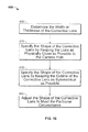
- the method includes providing a corrective lens to counteract a phase shift of surface acoustic waves propagating over the window, the window being an uncoated area in the border layer; determining a height of the corrective lens; and specifying a shape of the corrective lens that is physically close to, and has a symmetrical outline relative to, the window.
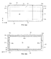
- Figs. 2(a) and 2(b) are front and back views of the touch substrate 5 shown in Fig. 1 .
- Fig. 2(a) which is a plan view of the front surface 10
- the acoustic transducers 35a, 35b, 35c, 35d are shown in dotted line to provide a frame of reference in relation to Fig. 2(b) , which is a plan view of the back surface 15, where the transducers 35a, 35b, 35c, 35d are situated and shown in solid line.
- the peripheral region 14 is shown in dotted line in Figs. 2(a) and 2(b) .
- X-Y coordinate axes are shown in Figs. 2(a) and 2(b) .
- the front surface 10 has an inner portion 13 shown within dotted lines in Fig. 2(a) and an outer/peripheral portion 14 external to the inner portion 13.
- the inner and outer portions 13, 14 form a nominal touch region on which the object 30 creates a contact to provide input according to the graphical user interface shown on the display 25 (shown in Fig. 1 ) disposed behind the back surface 15 and visible through the transparent substrate 5.
- the nominal touch region may also comprise the curved connecting surfaces 20 or portions thereof.
- the inner portion 13 not covered by a bezel forms the touch region.
- the touch sensor 1 has two pairs of transducers 35 respectively for the X and Y axes that are located in the peripheral region 14 of the back surface 15.
- the two pairs of transducers 35 are disposed at right angles to define a two-dimensional coordinate system.
- a first transmitting transducer 35a is placed in a Y-axis transmitting area and a second transmitting transducer 35b is placed in an X-axis transmitting area.
- a first receiving transducer 35c is placed in a Y-axis receiving area opposite the Y-axis transmitting area.
- a second receiving transducer 35d is placed in an X-axis receiving area opposite the X-axis transmitting area.
- the first transmitting transducer 35a and first receiving transducer 35c are used to measure Y coordinates of touch positions on the front substrate 10, and the second transmitting transducer 35b and second receiving transducer 35d are used to measure X coordinates of touch positions of on the front substrate 10.
- Each transducer 35 may either transmit or receive a surface acoustic wave, symmetrically.
- the touch sensor 1 also includes a pair of Y-axis reflective arrays 40a, 40b and a pair of X-axis reflective arrays 40c, 40d that are located in the peripheral region 14 of the back surface 15 in the respective transmitting and receiving areas.
- the reflective arrays 40 reflect a surface acoustic wave in a desired direction, as described below.
- the touch sensor 1 is operatively connected with a control system 29 (shown in Fig. 1 ) for the associated computer or computing device that integrates the sensor 1.
- the control system 29 generates an electronic signal that excites the transmitting transducers 35a, 35b to generate respective surface acoustic waves (or wave pulses).
- the control system 29 also receives respective electrical signals transduced by the receiving transducers 35c, 35d from the received surface acoustic waves.
- the control system 29, as used herein, means electronics typically including a microprocessor with firmware and electronics to generate excitation signals and to receive back and analyze signals from the touch sensor 1.
- the elements of the first Y-axis reflective array 40a each couple or reflect part of the surface acoustic waves to travel a) from the first Y-axis reflective array 40a outwardly along the negative (-) X-axis direction toward and around the proximate curved connecting surface 20; b) along the positive (+) X-axis direction across the front surface 10 toward and around the opposing curved connecting surface 20; and then c) along the negative (-) X-axis direction to the second Y-axis reflective array 40b on the back surface 15.
- the elements of the second Y-axis reflective array 40b each transmit the received surface acoustic waves to an adjacent element of the array 40b so that the waves continue traveling along the second Y-axis reflective array 40b along the positive (+) Y-axis direction to the first receiving transducer 35c.
- the second transmitting transducer 35b generates surface acoustic waves that travel along the negative (-) X-axis direction of the peripheral region 14 of the back surface 15 on which the first X-axis reflective array 40c is situated.
- the elements of the first X-axis reflective array 40c each transmit part of the surface acoustic waves to an adjacent element of the array 40c. Also, as seen by the solid line arrows indicating the wave propagation path in Figs.
- the elements of the first X-axis reflective array 40c each couple or reflect part of the surface acoustic waves to travel a) from the first X-axis reflective array 40c outwardly along the negative (-) Y-axis direction toward and around the proximate curved connecting surface 20, b) along the positive (+) Y-axis direction across the front surface 10 toward and around the opposing curved connecting surface 20; and then c) along the negative (-) Y-axis direction to the second X-axis reflective array 40d on the back surface 15.
- the elements of the second X-axis reflective array 40d each transmit the received surface acoustic waves to an adjacent element of the array 40d so that the waves continue traveling along the second X-axis reflective array 40d along the positive (+) X-axis direction to the second receiving transducer 35d.
- a touch of the nominal touch region 13, 14 by an object 30, such as finger or stylus absorbs a portion of the energy of the surface acoustic waves propagating across the front surface 10 and causes an attenuation of the waves passing through the point of touch.
- the resulting attenuation is detected by the receiving transducers 35c, 35d as a perturbation in the acoustic signal.
- the control system processes and analyzes the electrical signals transduced by the receiving transducers 35c, 35d, including those related to waveform perturbations, to detect the touch coordinates and position information. Further, the control system maps the touch coordinates and position information to the appropriate control actions of the user interface shown in the display 25 that is generally placed behind the back surface 15.
- the acoustic touch sensor 1 thus provides an XY coordinate input device system.
- the border layer 27 is generally acoustically benign, i.e., it propagates surface acoustic waves without rapid attenuation, preferably resulting in only small changes to the surface acoustic wave's velocity of propagation for easier manufacturing control of the wave's velocity despite factional changes in material thickness.
- the border layer 27 may be an inorganic black paint made of ceramic frit or porcelain enamel types of material.
- the periphery functional elements, i.e., the transducers 135 and the reflective arrays 140, are printed on top of the border layer 27 so that the elements are hidden from view through the substrate 105 which is typically transparent.
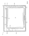
- the peripheral or border region 114 may include an area without a border layer (i.e., a paint-free or ink-free area) to form a window or hole 156, shown disposed between the second X-axis reflective array 140d and the sealing foam 154 and substantially aligned with the centerline of the back surface 115 that is perpendicular to the array 140d.
- the camera hole 156 is not an actual hole in the substrate 105.
- the camera hole 156 forms an optical window or part of an unobstructed optical path that extends from a camera lens (not shown) that is situated behind the back surface 115, through the camera hole 156, the back surface 115; the border layer 27 and the transparent substrate 105, and through a front surface 110 which faces the environment outside the touch sensor 101.
- the camera lens may be operatively part of a camera that is part of the associated computer or computing device that integrates the sensor 101 and a user interface display 25 (also situated behind the back surface 115).
- a compensating or corrective acoustic lens 160 (shown in Fig. 4 ) is disposed in the peripheral region 114 of the back surface 115 within the border layer 27.
- the corrective acoustic lens 160 is formed adjacent the camera hole 156 and is shown as a crescent-shaped or meniscus-shaped element in Fig. 4.
- Fig. 4 is a plan view of the back surface 115 of the substrate 105 constructed in accordance with a specific embodiment of the present invention.
- the mechanical properties of border layer materials of practical engineering interest reduce the velocity of propagation of surface acoustic waves (SAW) when the border layer 27 coats a glass surface like the substrate 105.
- SAW surface acoustic waves
- the corrective lens 160 may be formed or printed in the same operation as the reflector arrays 140 using the same acoustic material. Alternatively the corrective lens 160 can be printed in the same operation as the logo/icon (shown in the figure) using the same material. Further, the corrective lens 160 can be printed in a separate operation using a different material. Note, although the present invention is described herein with respect to the common case of the border layer 27 decreasing the SAW velocity, the present invention may be applied to the case in which the border layer 27 increases SAW velocity.
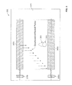
- the simulations were conducted using transmitting and receiving X-axis transducers 335b, 335d and first and second X-axis reflective arrays 340c, 340d; a control system routine to collect the signals at the transducers 335; and two different models of the camera hole 356, each with and without a corrective lens 360.
- the area of the back surface 315 containing the wave perturbations corresponding to the camera hole 356 was enlarged to allow modeling of the corrective lens 360.
- Fig. 5 illustrates a basic grid layout of the surface 315 of the substrate 305 (i.e., Schott B270TM glass) in the simulation series.
- the models of the camera hole 356 and the corrective lens 360 are positioned immediately above the midpoint of the second X-axis reflective array 340d.
- the border layer 27, although not shown, is understood to be on surface 315 to underlie the X-axis reflective arrays 340 and the corrective lens 360 and surround the camera hole 356.
- the velocities of propagation of the border layer and of the camera hole 356 model were set to the values of 3010 m/s and 3048 m/s, respectively, representing mild wave perturbations.
- Fig. 5 the surface acoustic waves generated by the transmitting X-axis transducer 335b are reflected downward by the first X-axis reflective array 340c and then reflected by the second X-axis reflective array 340d to the receiving X-axis transducer 335d. Comparing Fig. 5 to Figs. 3 and 4 , it is evident that a number of simplifications have been made to render the simulation calculations more manageable.
- the reflector arrays shown in Fig. 5 are not configured so that the SAW signals do not travel around the edges of substrate 305 for a bezel-less touch sensor (such as shown in Fig. 1 ) but are configured to propagate across surface 315. Nevertheless, the simulation model of Fig. 5 is sufficient to demonstrate key principles of the corrective lens 360 and the present invention.
- Fig. 8 plots the grid amplitudes for a simulation including a circular camera hole 356 without a corrective lens 360.
- the apparent phase shifting of the wave crests propagate through the second reflective array 340d directly below the camera hole 356.
- the phase shifts are actually exaggerated by the steps used to generate the simulation images (e.g., for a camera hole 356 of diameter 6.4 mm, the time phase shift is approximately 57 degrees for a surface acoustic wave passing through the hole 356 center).
- the simulation grid is sampled every 7 th grid point in the amplitude images. This results in a Moire-type exaggeration of periodic patterns within the wave crests.
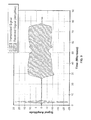
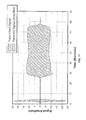
- Fig. 9 plots the transmitted and received signals for the simulation of Fig. 8 (including the circular camera hole 356 without the corrective lens 360). As compared to the plot of Fig. 7 , the plot of Fig. 9 shows a resulting dip in the received signal that is produced by the camera hole 356.
- Fig. 12 plots the grid amplitudes for a simulation including a rectangular camera hole 356 without a corrective lens 360 (It is noted that rectangular camera holes are typically square). As compared to the plot of Fig. 6 , the plot of Fig. 12 shows the apparent phase shifting of the wave crests propagating through the second reflective array 340d directly below the camera hole 356. Fig. 13 plots the transmitted and received signals for the simulation of Fig. 12 (including a rectangular camera hole 356 without a corrective lens 360). As compared to the plot of Fig. 7 , the plot of Fig. 13 shows a definite dip in the received signal that is produced by the rectangular camera hole 356.
- Fig. 14 plots the grid amplitudes for a simulation including a rectangular camera hole 356 with a rectangular corrective lens 360 (However, it is noted that the corrective lens 360 need not be square in the case the camera hole 356 is square). As compared to the plot of Fig. 12 , the phase shift of the wave crests below the camera hole 356 is eliminated.
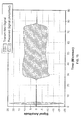
- Fig. 15 plots the transmitted and received signals for the simulation of Fig. 14 (including the rectangular camera hole 356 and a rectangular corrective lens 360). As compared to the plot of Fig. 13 , the plot of Fig. 15 shows that the dip in the received signal is eliminated.
- the method 400 assumes that all surface acoustic wave paths across the surface 315 of the substrate 305 are straight and adjusts the lens 360 height to cancel the total phase shift along all paths through the camera hole and lens system.
- the method 400 first determines the height of the corrective lens 360 (Step 410).
- the velocities of propagation of the surface acoustic waves are defined as follows:
- the method 400 also assumes, as an example, that a surface acoustic wave is propagating in the Y-axis direction through the camera hole 356 having a dimension y(x) along the Y-axis (or height) and a dimension x along the X-axis (or width), as shown in Fig. 17 .
- the direction of wave propagation determines the direction for the analysis, which in this case is the Y-axis direction since the camera hole 356 is near the top center of the substrate 205. If the camera hole 356 were placed at/near the center of the right side of the substrate 105, the direction for analysis would be the X-axis direction.
- the shape of the camera hole 356 and its location are assumed to be known (for example, as specified by a customer having a specific camera and camera lens size in mind). Also, for this analysis, the origin of the X axis may be freely chosen for convenience purposes, for example, at the center of the camera hole 356. Similarly, the method 400 assumes that the corrective lens 360 has an unknown height y'(x) along each X-coordinate to be solved.
- Phase Shift lens - Phase Shift camera hole
- Equations 7 and 8 specify the heightof the corrective lens 360 but not the overall shape.
- the method 400 uses two general guidelines for this purpose. First, the corrective lens 360 should be kept as physically close as possible to the camera hole 356 (Step 420). This will minimize ray scattering (refraction) effects. Second, the outline of the corrective lens 360 should be as symmetrical as possible (Step 430). This can also help to minimize refraction effects.
- An example of a corrective lens 360 for a circular camera hole 356 that follows both of these guidelines is the two-sided meniscus lens shown in Fig. 18 . The result is that the magnitude of the velocity shifts caused by the camera hole 356 and the corrective lens 360 (relative to the surrounding border layer) are approximately equal and opposite in sign.
- the guidelines may be adjusted to suit the particular circumstance (Step 440). For example, if there is no room on the periphery of the back surface 315 to print a corrective lens 360 on a particular side of the camera hole 356, then a single-sided lens may be used (as shown in Figs. 10 , 14 and 17 ). This approximates canceling the phase shift of the camera hole 356.
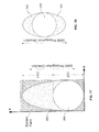
- FIGs. 19 and 20 are simplified cross-sectional views of an acoustic touch sensor 1, where the border layer 27 of Fig. 1 is not used but instead the optical properties of the glass substrate 5 are modified so that the border region 14 of the substrate 5 is changed from being transparent to being opaque or colored to provide a "modified border region 14' " of the substrate 5.
- common soda lime glass can be modified to have darker color than similarly electron-beamed borosilicate glass, likely due to the visible band arising from electrons trapped by oxygen vacancies neighboring alkali ions in the glass.
- the glass material of the substrate 5 may be selected to maximize or optimize the color change for a given electronic beaming dose or stain exposure.
- Fig. 19 shows the discoloration of the glass substrate 5 in the modified border region 14' (except for the camera hole area or window) has occurred from the back surface 15 to the front surface 10, assuming that the electron beaming or staining is performed on the back surface 15.
- Fig. 19 shows the discoloration entirely through the thickness of the glass substrate 5 (a more plausible result of electron beaming than for staining)
- the discoloration may be darker toward the back surface 15 than the front surface 10.
- Fig. 20 shows the discoloration of the glass substrate 5 in the modified border region 14' (except for the camera hole area) only partially through the glass substrate 5 and concentrated at the back surface 15, again assuming that the electron beaming or staining is performed on the back surface 15.
- optical properties of the substrate 5 are modified in a way that has negligible effect on the mechanical properties of the substrate 5, and hence no significant effect on the propagation of surface acoustic waves including leaving the SAW phase velocity essentially unchanged.
- no corrective acoustic lens would be required for the camera hole since with no SAW phase velocity change there are no phase shifts to be corrected.
- the modified border region 14' obtains a similar result as a corrective lens in preventing signal variations caused by the camera hole.
- the steps of the method 400 have been described in a specific sequence, the order of the steps may be re-ordered in part or in whole and the steps may be modified, supplemented, or omitted as appropriate.
- the method 400 may use various well known algorithms and software applications to implement the steps and substeps. Further, the method 400 may be implemented in a variety of algorithms and software applications. Further, the method 400 may be supplemented by additional steps or techniques.
Landscapes
- Engineering & Computer Science (AREA)
- Theoretical Computer Science (AREA)
- Physics & Mathematics (AREA)
- General Engineering & Computer Science (AREA)
- Human Computer Interaction (AREA)
- General Physics & Mathematics (AREA)
- Computer Hardware Design (AREA)
- Acoustics & Sound (AREA)
- Position Input By Displaying (AREA)
- Length Measuring Devices Characterised By Use Of Acoustic Means (AREA)
Applications Claiming Priority (1)
| Application Number | Priority Date | Filing Date | Title |
|---|---|---|---|
| US13/274,236 US8823685B2 (en) | 2011-10-14 | 2011-10-14 | Acoustic touch apparatus |
Publications (3)
| Publication Number | Publication Date |
|---|---|
| EP2581815A2 true EP2581815A2 (de) | 2013-04-17 |
| EP2581815A3 EP2581815A3 (de) | 2013-07-10 |
| EP2581815B1 EP2581815B1 (de) | 2016-04-06 |
Family
ID=47177762
Family Applications (1)
| Application Number | Title | Priority Date | Filing Date |
|---|---|---|---|
| EP12188142.9A Active EP2581815B1 (de) | 2011-10-14 | 2012-10-11 | Akustische Berührungsvorrichtung |
Country Status (5)
| Country | Link |
|---|---|
| US (1) | US8823685B2 (de) |
| EP (1) | EP2581815B1 (de) |
| JP (1) | JP5531075B2 (de) |
| CN (1) | CN103049142B (de) |
| TW (1) | TWI488094B (de) |
Cited By (2)
| Publication number | Priority date | Publication date | Assignee | Title |
|---|---|---|---|---|
| CN106919296A (zh) * | 2017-03-23 | 2017-07-04 | 安徽玖信光电科技有限公司 | 一种表面声波触控屏 |
| CN110658956A (zh) * | 2019-10-10 | 2020-01-07 | 业成科技(成都)有限公司 | 超声波触控装置及其制作方法 |
Families Citing this family (32)
| Publication number | Priority date | Publication date | Assignee | Title |
|---|---|---|---|---|
| US9639213B2 (en) | 2011-04-26 | 2017-05-02 | Sentons Inc. | Using multiple signals to detect touch input |
| US9189109B2 (en) | 2012-07-18 | 2015-11-17 | Sentons Inc. | Detection of type of object used to provide a touch contact input |
| US11327599B2 (en) | 2011-04-26 | 2022-05-10 | Sentons Inc. | Identifying a contact type |
| US9477350B2 (en) | 2011-04-26 | 2016-10-25 | Sentons Inc. | Method and apparatus for active ultrasonic touch devices |
| US10198097B2 (en) | 2011-04-26 | 2019-02-05 | Sentons Inc. | Detecting touch input force |
| US10235004B1 (en) | 2011-11-18 | 2019-03-19 | Sentons Inc. | Touch input detector with an integrated antenna |
| US9449476B2 (en) | 2011-11-18 | 2016-09-20 | Sentons Inc. | Localized haptic feedback |
| US9099971B2 (en) | 2011-11-18 | 2015-08-04 | Sentons Inc. | Virtual keyboard interaction using touch input force |
| US9513727B2 (en) | 2012-07-18 | 2016-12-06 | Sentons Inc. | Touch input surface microphone |
| US9524063B2 (en) | 2012-07-18 | 2016-12-20 | Sentons Inc. | Detection of a number of touch contacts of a multi-touch input |
| US9348468B2 (en) | 2013-06-07 | 2016-05-24 | Sentons Inc. | Detecting multi-touch inputs |
| US9690384B1 (en) * | 2012-09-26 | 2017-06-27 | Amazon Technologies, Inc. | Fingertip location determinations for gesture input |
| US9128567B2 (en) * | 2012-11-20 | 2015-09-08 | Elo Touch Solutions, Inc. | Segmented waveguide core touch sensor systems and methods |
| TWI494827B (zh) * | 2013-08-28 | 2015-08-01 | Au Optronics Corp | 感測裝置與定位方法 |
| KR102126276B1 (ko) * | 2013-08-30 | 2020-06-25 | 삼성디스플레이 주식회사 | 유기 발광 표시 장치 |
| US9588552B2 (en) | 2013-09-11 | 2017-03-07 | Sentons Inc. | Attaching electrical components using non-conductive adhesive |
| US9459715B1 (en) | 2013-09-20 | 2016-10-04 | Sentons Inc. | Using spectral control in detecting touch input |
| US9880671B2 (en) | 2013-10-08 | 2018-01-30 | Sentons Inc. | Damping vibrational wave reflections |
| US9424984B2 (en) * | 2014-03-05 | 2016-08-23 | Wisconsin Alumni Research Foundation | Integrated capacitor and inductor having co-located magnetic and electrical energy storage volumes |
| US10048811B2 (en) | 2015-09-18 | 2018-08-14 | Sentons Inc. | Detecting touch input provided by signal transmitting stylus |
| US10908741B2 (en) | 2016-11-10 | 2021-02-02 | Sentons Inc. | Touch input detection along device sidewall |
| US10296144B2 (en) | 2016-12-12 | 2019-05-21 | Sentons Inc. | Touch input detection with shared receivers |
| US10126877B1 (en) | 2017-02-01 | 2018-11-13 | Sentons Inc. | Update of reference data for touch input detection |
| US10585522B2 (en) | 2017-02-27 | 2020-03-10 | Sentons Inc. | Detection of non-touch inputs using a signature |
| WO2018205275A1 (en) * | 2017-05-12 | 2018-11-15 | Microsoft Technology Licensing, Llc. | Touch operated surface |
| US11334196B2 (en) * | 2017-05-24 | 2022-05-17 | Apple Inc. | System and method for acoustic touch and force sensing |
| CN208722170U (zh) | 2017-05-24 | 2019-04-09 | 苹果公司 | 触摸和力敏设备,电子设备及可穿戴音频设备 |
| US11009411B2 (en) | 2017-08-14 | 2021-05-18 | Sentons Inc. | Increasing sensitivity of a sensor using an encoded signal |
| US11580829B2 (en) | 2017-08-14 | 2023-02-14 | Sentons Inc. | Dynamic feedback for haptics |
| CN107608571A (zh) * | 2017-09-05 | 2018-01-19 | 捷开通讯(深圳)有限公司 | 一种声波触控设备及终端 |
| CN108008765A (zh) * | 2017-11-22 | 2018-05-08 | 广东欧珀移动通信有限公司 | 电子设备 |
| TWI886897B (zh) * | 2024-04-11 | 2025-06-11 | 宏碁股份有限公司 | 超音波反射板及輸入系統 |
Family Cites Families (11)
| Publication number | Priority date | Publication date | Assignee | Title |
|---|---|---|---|---|
| US4231260A (en) | 1978-11-03 | 1980-11-04 | The Charles Stark Draper Laboratory, Inc. | Position determining system |
| US8421776B2 (en) | 1996-08-12 | 2013-04-16 | Elo Touch Solutions, Inc. | Acoustic condition sensor employing a plurality of mutually non-orthogonal waves |
| BR9714435B1 (pt) | 1996-12-25 | 2010-07-27 | dispositivo sensìvel a toque acústico, substrato para um dispositivo sensìvel acústico e processo de detectar o toque sobre um substrato. | |
| CA2288299C (en) * | 1997-04-24 | 2006-11-07 | Tyco Electronics Corporation | Organic matrix for acoustic reflector array |
| JP4024933B2 (ja) | 1998-08-18 | 2007-12-19 | タッチパネル・システムズ株式会社 | タッチパネル |
| US6225985B1 (en) * | 1999-03-26 | 2001-05-01 | Elo Touchsystems, Inc. | Acoustic touchscreen constructed directly on a cathode ray tube |
| US6506171B1 (en) | 2000-07-27 | 2003-01-14 | Insightec-Txsonics, Ltd | System and methods for controlling distribution of acoustic energy around a focal point using a focused ultrasound system |
| TW591502B (en) | 2003-03-11 | 2004-06-11 | Onetouch Technologies Co Ltd | Design method of the reflective streaks on ultrasonic touch screen |
| US7274358B2 (en) | 2004-01-06 | 2007-09-25 | Tyco Electronics Corporation | Focusing-shaped reflector arrays for acoustic touchscreens |
| EP2324410A2 (de) | 2008-07-15 | 2011-05-25 | 3M Innovative Properties Company | Systeme und verfahren zur korrektur von geschwindigkeitsvariationen einer signalausbreitung über eine berührungskontaktfläche |
| US8576202B2 (en) | 2010-03-25 | 2013-11-05 | Elo Touch Solutions, Inc. | Bezel-less acoustic touch apparatus |
-
2011
- 2011-10-14 US US13/274,236 patent/US8823685B2/en active Active
-
2012
- 2012-10-11 EP EP12188142.9A patent/EP2581815B1/de active Active
- 2012-10-12 TW TW101137814A patent/TWI488094B/zh not_active IP Right Cessation
- 2012-10-12 JP JP2012227260A patent/JP5531075B2/ja not_active Expired - Fee Related
- 2012-10-15 CN CN201210390521.3A patent/CN103049142B/zh active Active
Cited By (3)
| Publication number | Priority date | Publication date | Assignee | Title |
|---|---|---|---|---|
| CN106919296A (zh) * | 2017-03-23 | 2017-07-04 | 安徽玖信光电科技有限公司 | 一种表面声波触控屏 |
| CN110658956A (zh) * | 2019-10-10 | 2020-01-07 | 业成科技(成都)有限公司 | 超声波触控装置及其制作方法 |
| CN110658956B (zh) * | 2019-10-10 | 2022-06-21 | 业成科技(成都)有限公司 | 超声波触控装置及其制作方法 |
Also Published As
| Publication number | Publication date |
|---|---|
| EP2581815B1 (de) | 2016-04-06 |
| CN103049142A (zh) | 2013-04-17 |
| JP2013089246A (ja) | 2013-05-13 |
| JP5531075B2 (ja) | 2014-06-25 |
| CN103049142B (zh) | 2016-07-06 |
| US20130093731A1 (en) | 2013-04-18 |
| TW201333789A (zh) | 2013-08-16 |
| TWI488094B (zh) | 2015-06-11 |
| EP2581815A3 (de) | 2013-07-10 |
| US8823685B2 (en) | 2014-09-02 |
Similar Documents
| Publication | Publication Date | Title |
|---|---|---|
| EP2581815B1 (de) | Akustische Berührungsvorrichtung | |
| EP2766798B1 (de) | Verbesserte akustische berührungsvorrichtung | |
| US10678379B2 (en) | Bezel-less acoustic touch apparatus | |
| CN102754056B (zh) | 用于感测显示器上触摸事件的方法和装置 | |
| EP2972704B1 (de) | Akustische berührungsvorrichtung und verfahren mit berührungsempfindlichen lambwellen | |
| US20140104196A1 (en) | Curved profile touch sensor systems and methods |
Legal Events
| Date | Code | Title | Description |
|---|---|---|---|
| PUAI | Public reference made under article 153(3) epc to a published international application that has entered the european phase |
Free format text: ORIGINAL CODE: 0009012 |
|
| AK | Designated contracting states |
Kind code of ref document: A2 Designated state(s): AL AT BE BG CH CY CZ DE DK EE ES FI FR GB GR HR HU IE IS IT LI LT LU LV MC MK MT NL NO PL PT RO RS SE SI SK SM TR |
|
| AX | Request for extension of the european patent |
Extension state: BA ME |
|
| PUAL | Search report despatched |
Free format text: ORIGINAL CODE: 0009013 |
|
| AK | Designated contracting states |
Kind code of ref document: A3 Designated state(s): AL AT BE BG CH CY CZ DE DK EE ES FI FR GB GR HR HU IE IS IT LI LT LU LV MC MK MT NL NO PL PT RO RS SE SI SK SM TR |
|
| AX | Request for extension of the european patent |
Extension state: BA ME |
|
| RIC1 | Information provided on ipc code assigned before grant |
Ipc: G06F 1/16 20060101ALI20130606BHEP Ipc: G06F 3/043 20060101AFI20130606BHEP |
|
| 17P | Request for examination filed |
Effective date: 20140109 |
|
| RBV | Designated contracting states (corrected) |
Designated state(s): AL AT BE BG CH CY CZ DE DK EE ES FI FR GB GR HR HU IE IS IT LI LT LU LV MC MK MT NL NO PL PT RO RS SE SI SK SM TR |
|
| 17Q | First examination report despatched |
Effective date: 20140606 |
|
| GRAP | Despatch of communication of intention to grant a patent |
Free format text: ORIGINAL CODE: EPIDOSNIGR1 |
|
| INTG | Intention to grant announced |
Effective date: 20150930 |
|
| GRAS | Grant fee paid |
Free format text: ORIGINAL CODE: EPIDOSNIGR3 |
|
| GRAA | (expected) grant |
Free format text: ORIGINAL CODE: 0009210 |
|
| AK | Designated contracting states |
Kind code of ref document: B1 Designated state(s): AL AT BE BG CH CY CZ DE DK EE ES FI FR GB GR HR HU IE IS IT LI LT LU LV MC MK MT NL NO PL PT RO RS SE SI SK SM TR |
|
| REG | Reference to a national code |
Ref country code: GB Ref legal event code: FG4D |
|
| REG | Reference to a national code |
Ref country code: AT Ref legal event code: REF Ref document number: 788454 Country of ref document: AT Kind code of ref document: T Effective date: 20160415 Ref country code: CH Ref legal event code: EP |
|
| REG | Reference to a national code |
Ref country code: IE Ref legal event code: FG4D |
|
| REG | Reference to a national code |
Ref country code: DE Ref legal event code: R096 Ref document number: 602012016534 Country of ref document: DE |
|
| REG | Reference to a national code |
Ref country code: LT Ref legal event code: MG4D Ref country code: NL Ref legal event code: MP Effective date: 20160406 |
|
| REG | Reference to a national code |
Ref country code: AT Ref legal event code: MK05 Ref document number: 788454 Country of ref document: AT Kind code of ref document: T Effective date: 20160406 |
|
| PG25 | Lapsed in a contracting state [announced via postgrant information from national office to epo] |
Ref country code: NL Free format text: LAPSE BECAUSE OF FAILURE TO SUBMIT A TRANSLATION OF THE DESCRIPTION OR TO PAY THE FEE WITHIN THE PRESCRIBED TIME-LIMIT Effective date: 20160406 |
|
| PG25 | Lapsed in a contracting state [announced via postgrant information from national office to epo] |
Ref country code: PL Free format text: LAPSE BECAUSE OF FAILURE TO SUBMIT A TRANSLATION OF THE DESCRIPTION OR TO PAY THE FEE WITHIN THE PRESCRIBED TIME-LIMIT Effective date: 20160406 Ref country code: FI Free format text: LAPSE BECAUSE OF FAILURE TO SUBMIT A TRANSLATION OF THE DESCRIPTION OR TO PAY THE FEE WITHIN THE PRESCRIBED TIME-LIMIT Effective date: 20160406 Ref country code: IS Free format text: LAPSE BECAUSE OF FAILURE TO SUBMIT A TRANSLATION OF THE DESCRIPTION OR TO PAY THE FEE WITHIN THE PRESCRIBED TIME-LIMIT Effective date: 20160806 Ref country code: NO Free format text: LAPSE BECAUSE OF FAILURE TO SUBMIT A TRANSLATION OF THE DESCRIPTION OR TO PAY THE FEE WITHIN THE PRESCRIBED TIME-LIMIT Effective date: 20160706 Ref country code: LT Free format text: LAPSE BECAUSE OF FAILURE TO SUBMIT A TRANSLATION OF THE DESCRIPTION OR TO PAY THE FEE WITHIN THE PRESCRIBED TIME-LIMIT Effective date: 20160406 |
|
| PG25 | Lapsed in a contracting state [announced via postgrant information from national office to epo] |
Ref country code: GR Free format text: LAPSE BECAUSE OF FAILURE TO SUBMIT A TRANSLATION OF THE DESCRIPTION OR TO PAY THE FEE WITHIN THE PRESCRIBED TIME-LIMIT Effective date: 20160707 Ref country code: RS Free format text: LAPSE BECAUSE OF FAILURE TO SUBMIT A TRANSLATION OF THE DESCRIPTION OR TO PAY THE FEE WITHIN THE PRESCRIBED TIME-LIMIT Effective date: 20160406 Ref country code: LV Free format text: LAPSE BECAUSE OF FAILURE TO SUBMIT A TRANSLATION OF THE DESCRIPTION OR TO PAY THE FEE WITHIN THE PRESCRIBED TIME-LIMIT Effective date: 20160406 Ref country code: AT Free format text: LAPSE BECAUSE OF FAILURE TO SUBMIT A TRANSLATION OF THE DESCRIPTION OR TO PAY THE FEE WITHIN THE PRESCRIBED TIME-LIMIT Effective date: 20160406 Ref country code: PT Free format text: LAPSE BECAUSE OF FAILURE TO SUBMIT A TRANSLATION OF THE DESCRIPTION OR TO PAY THE FEE WITHIN THE PRESCRIBED TIME-LIMIT Effective date: 20160808 Ref country code: SE Free format text: LAPSE BECAUSE OF FAILURE TO SUBMIT A TRANSLATION OF THE DESCRIPTION OR TO PAY THE FEE WITHIN THE PRESCRIBED TIME-LIMIT Effective date: 20160406 Ref country code: HR Free format text: LAPSE BECAUSE OF FAILURE TO SUBMIT A TRANSLATION OF THE DESCRIPTION OR TO PAY THE FEE WITHIN THE PRESCRIBED TIME-LIMIT Effective date: 20160406 Ref country code: ES Free format text: LAPSE BECAUSE OF FAILURE TO SUBMIT A TRANSLATION OF THE DESCRIPTION OR TO PAY THE FEE WITHIN THE PRESCRIBED TIME-LIMIT Effective date: 20160406 |
|
| PG25 | Lapsed in a contracting state [announced via postgrant information from national office to epo] |
Ref country code: BE Free format text: LAPSE BECAUSE OF FAILURE TO SUBMIT A TRANSLATION OF THE DESCRIPTION OR TO PAY THE FEE WITHIN THE PRESCRIBED TIME-LIMIT Effective date: 20160406 Ref country code: IT Free format text: LAPSE BECAUSE OF FAILURE TO SUBMIT A TRANSLATION OF THE DESCRIPTION OR TO PAY THE FEE WITHIN THE PRESCRIBED TIME-LIMIT Effective date: 20160406 |
|
| REG | Reference to a national code |
Ref country code: DE Ref legal event code: R097 Ref document number: 602012016534 Country of ref document: DE |
|
| PG25 | Lapsed in a contracting state [announced via postgrant information from national office to epo] |
Ref country code: DK Free format text: LAPSE BECAUSE OF FAILURE TO SUBMIT A TRANSLATION OF THE DESCRIPTION OR TO PAY THE FEE WITHIN THE PRESCRIBED TIME-LIMIT Effective date: 20160406 Ref country code: SK Free format text: LAPSE BECAUSE OF FAILURE TO SUBMIT A TRANSLATION OF THE DESCRIPTION OR TO PAY THE FEE WITHIN THE PRESCRIBED TIME-LIMIT Effective date: 20160406 Ref country code: CZ Free format text: LAPSE BECAUSE OF FAILURE TO SUBMIT A TRANSLATION OF THE DESCRIPTION OR TO PAY THE FEE WITHIN THE PRESCRIBED TIME-LIMIT Effective date: 20160406 Ref country code: RO Free format text: LAPSE BECAUSE OF FAILURE TO SUBMIT A TRANSLATION OF THE DESCRIPTION OR TO PAY THE FEE WITHIN THE PRESCRIBED TIME-LIMIT Effective date: 20160406 Ref country code: EE Free format text: LAPSE BECAUSE OF FAILURE TO SUBMIT A TRANSLATION OF THE DESCRIPTION OR TO PAY THE FEE WITHIN THE PRESCRIBED TIME-LIMIT Effective date: 20160406 |
|
| PLBE | No opposition filed within time limit |
Free format text: ORIGINAL CODE: 0009261 |
|
| STAA | Information on the status of an ep patent application or granted ep patent |
Free format text: STATUS: NO OPPOSITION FILED WITHIN TIME LIMIT |
|
| PG25 | Lapsed in a contracting state [announced via postgrant information from national office to epo] |
Ref country code: SM Free format text: LAPSE BECAUSE OF FAILURE TO SUBMIT A TRANSLATION OF THE DESCRIPTION OR TO PAY THE FEE WITHIN THE PRESCRIBED TIME-LIMIT Effective date: 20160406 |
|
| 26N | No opposition filed |
Effective date: 20170110 |
|
| PG25 | Lapsed in a contracting state [announced via postgrant information from national office to epo] |
Ref country code: SI Free format text: LAPSE BECAUSE OF FAILURE TO SUBMIT A TRANSLATION OF THE DESCRIPTION OR TO PAY THE FEE WITHIN THE PRESCRIBED TIME-LIMIT Effective date: 20160406 |
|
| REG | Reference to a national code |
Ref country code: CH Ref legal event code: PL |
|
| GBPC | Gb: european patent ceased through non-payment of renewal fee |
Effective date: 20161011 |
|
| REG | Reference to a national code |
Ref country code: IE Ref legal event code: MM4A |
|
| REG | Reference to a national code |
Ref country code: FR Ref legal event code: ST Effective date: 20170630 |
|
| PG25 | Lapsed in a contracting state [announced via postgrant information from national office to epo] |
Ref country code: LI Free format text: LAPSE BECAUSE OF NON-PAYMENT OF DUE FEES Effective date: 20161031 Ref country code: GB Free format text: LAPSE BECAUSE OF NON-PAYMENT OF DUE FEES Effective date: 20161011 Ref country code: CH Free format text: LAPSE BECAUSE OF NON-PAYMENT OF DUE FEES Effective date: 20161031 Ref country code: FR Free format text: LAPSE BECAUSE OF NON-PAYMENT OF DUE FEES Effective date: 20161102 |
|
| PG25 | Lapsed in a contracting state [announced via postgrant information from national office to epo] |
Ref country code: LU Free format text: LAPSE BECAUSE OF NON-PAYMENT OF DUE FEES Effective date: 20161011 |
|
| PG25 | Lapsed in a contracting state [announced via postgrant information from national office to epo] |
Ref country code: IE Free format text: LAPSE BECAUSE OF NON-PAYMENT OF DUE FEES Effective date: 20161011 |
|
| PG25 | Lapsed in a contracting state [announced via postgrant information from national office to epo] |
Ref country code: CY Free format text: LAPSE BECAUSE OF FAILURE TO SUBMIT A TRANSLATION OF THE DESCRIPTION OR TO PAY THE FEE WITHIN THE PRESCRIBED TIME-LIMIT Effective date: 20160406 Ref country code: HU Free format text: LAPSE BECAUSE OF FAILURE TO SUBMIT A TRANSLATION OF THE DESCRIPTION OR TO PAY THE FEE WITHIN THE PRESCRIBED TIME-LIMIT; INVALID AB INITIO Effective date: 20121011 |
|
| PG25 | Lapsed in a contracting state [announced via postgrant information from national office to epo] |
Ref country code: MK Free format text: LAPSE BECAUSE OF FAILURE TO SUBMIT A TRANSLATION OF THE DESCRIPTION OR TO PAY THE FEE WITHIN THE PRESCRIBED TIME-LIMIT Effective date: 20160406 Ref country code: TR Free format text: LAPSE BECAUSE OF FAILURE TO SUBMIT A TRANSLATION OF THE DESCRIPTION OR TO PAY THE FEE WITHIN THE PRESCRIBED TIME-LIMIT Effective date: 20160406 Ref country code: MC Free format text: LAPSE BECAUSE OF FAILURE TO SUBMIT A TRANSLATION OF THE DESCRIPTION OR TO PAY THE FEE WITHIN THE PRESCRIBED TIME-LIMIT Effective date: 20160406 Ref country code: MT Free format text: LAPSE BECAUSE OF NON-PAYMENT OF DUE FEES Effective date: 20161031 |
|
| PG25 | Lapsed in a contracting state [announced via postgrant information from national office to epo] |
Ref country code: BG Free format text: LAPSE BECAUSE OF FAILURE TO SUBMIT A TRANSLATION OF THE DESCRIPTION OR TO PAY THE FEE WITHIN THE PRESCRIBED TIME-LIMIT Effective date: 20160406 |
|
| PG25 | Lapsed in a contracting state [announced via postgrant information from national office to epo] |
Ref country code: AL Free format text: LAPSE BECAUSE OF FAILURE TO SUBMIT A TRANSLATION OF THE DESCRIPTION OR TO PAY THE FEE WITHIN THE PRESCRIBED TIME-LIMIT Effective date: 20160406 |
|
| P01 | Opt-out of the competence of the unified patent court (upc) registered |
Effective date: 20230520 |
|
| PGFP | Annual fee paid to national office [announced via postgrant information from national office to epo] |
Ref country code: DE Payment date: 20251028 Year of fee payment: 14 |