EP2581797A1 - Beacon collision avoidance method for a mobile robot system - Google Patents
Beacon collision avoidance method for a mobile robot system Download PDFInfo
- Publication number
- EP2581797A1 EP2581797A1 EP13151003.4A EP13151003A EP2581797A1 EP 2581797 A1 EP2581797 A1 EP 2581797A1 EP 13151003 A EP13151003 A EP 13151003A EP 2581797 A1 EP2581797 A1 EP 2581797A1
- Authority
- EP
- European Patent Office
- Prior art keywords
- mobile robot
- beacon
- signal
- response signal
- traveling
- Prior art date
- Legal status (The legal status is an assumption and is not a legal conclusion. Google has not performed a legal analysis and makes no representation as to the accuracy of the status listed.)
- Granted
Links
- 238000000034 method Methods 0.000 title claims abstract description 35
- 230000004044 response Effects 0.000 claims abstract description 87
- 238000013459 approach Methods 0.000 description 47
- 238000004140 cleaning Methods 0.000 description 27
- 125000001475 halogen functional group Chemical group 0.000 description 9
- 238000010586 diagram Methods 0.000 description 6
- 230000008054 signal transmission Effects 0.000 description 4
- 230000000694 effects Effects 0.000 description 3
- 230000006870 function Effects 0.000 description 2
- 239000000428 dust Substances 0.000 description 1
- 238000005265 energy consumption Methods 0.000 description 1
- 239000000463 material Substances 0.000 description 1
Images


Classifications
-
- G—PHYSICS
- G05—CONTROLLING; REGULATING
- G05D—SYSTEMS FOR CONTROLLING OR REGULATING NON-ELECTRIC VARIABLES
- G05D1/00—Control of position, course or altitude of land, water, air, or space vehicles, e.g. automatic pilot
- G05D1/02—Control of position or course in two dimensions
- G05D1/021—Control of position or course in two dimensions specially adapted to land vehicles
- G05D1/0231—Control of position or course in two dimensions specially adapted to land vehicles using optical position detecting means
- G05D1/0234—Control of position or course in two dimensions specially adapted to land vehicles using optical position detecting means using optical markers or beacons
-
- B—PERFORMING OPERATIONS; TRANSPORTING
- B25—HAND TOOLS; PORTABLE POWER-DRIVEN TOOLS; MANIPULATORS
- B25J—MANIPULATORS; CHAMBERS PROVIDED WITH MANIPULATION DEVICES
- B25J9/00—Programme-controlled manipulators
- B25J9/16—Programme controls
- B25J9/1674—Programme controls characterised by safety, monitoring, diagnostic
- B25J9/1676—Avoiding collision or forbidden zones
-
- B—PERFORMING OPERATIONS; TRANSPORTING
- B25—HAND TOOLS; PORTABLE POWER-DRIVEN TOOLS; MANIPULATORS
- B25J—MANIPULATORS; CHAMBERS PROVIDED WITH MANIPULATION DEVICES
- B25J11/00—Manipulators not otherwise provided for
- B25J11/008—Manipulators for service tasks
- B25J11/0085—Cleaning
-
- B—PERFORMING OPERATIONS; TRANSPORTING
- B25—HAND TOOLS; PORTABLE POWER-DRIVEN TOOLS; MANIPULATORS
- B25J—MANIPULATORS; CHAMBERS PROVIDED WITH MANIPULATION DEVICES
- B25J5/00—Manipulators mounted on wheels or on carriages
-
- B—PERFORMING OPERATIONS; TRANSPORTING
- B25—HAND TOOLS; PORTABLE POWER-DRIVEN TOOLS; MANIPULATORS
- B25J—MANIPULATORS; CHAMBERS PROVIDED WITH MANIPULATION DEVICES
- B25J9/00—Programme-controlled manipulators
- B25J9/0003—Home robots, i.e. small robots for domestic use
Landscapes
- Engineering & Computer Science (AREA)
- Robotics (AREA)
- Mechanical Engineering (AREA)
- Physics & Mathematics (AREA)
- Electromagnetism (AREA)
- Aviation & Aerospace Engineering (AREA)
- Radar, Positioning & Navigation (AREA)
- Remote Sensing (AREA)
- General Physics & Mathematics (AREA)
- Automation & Control Theory (AREA)
- Control Of Position, Course, Altitude, Or Attitude Of Moving Bodies (AREA)
Abstract
Description
- Embodiments relate to a mobile robot system to restrict a traveling region of a robot and to guide the robot to another region, and a method of controlling the same.
- Generally, a mobile robot is a device to perform an operation while autonomously traveling in a traveling region without user control. A robot cleaner which is a mobile robot sucks foreign materials such as dust from a floor while autonomously traveling in a predetermined cleaning region, such as a home or office, so as to perform a cleaning operation.
- In order to allow the mobile robot to perform the operation, the mobile robot is prevented from escaping from the traveling region. A virtual wall unit (hereinafter, referred to as a "beacon") to prevent the mobile robot from entering a border (e.g., a doorway or a division between a living room and a kitchen) of the traveling region is provided so as to restrict the traveling region of the mobile robot.
- The beacon to restrict the traveling region of the mobile robot continuously transmits an infrared ray (IR) signal to the border of the traveling region so as to generate a beam region. The mobile robot changes a traveling direction thereof so as not to cross the beam region when the IR signal is detected while the mobile robot travels in order to perform the operation, thereby performing avoidance navigation. The mobile robot performs avoidance navigation only when the signal transmitted from the beacon is detected. However, since the beacon continuously transmits the signal even when the mobile robot is not in a signal arrival range of the beacon, high power for transmitting the signal is unnecessarily wasted. Due to the unnecessary power consumption, a battery of the beacon is frequently charged and thus is frequently replaced with a new battery. Thus, a user may be dissatisfied with the life span of the battery.
- Therefore, it is an aspect to provide a mobile robot system to improve energy efficiency of a battery of a beacon by reporting a response signal to restrict a traveling region of a mobile robot to the mobile robot only when a remote controller reception module in the beacon detects a signal transmitted from the mobile robot with low power consumption, and a method of controlling the same.
- Additional aspects and/or advantages will be set forth in part in the description which follows and, in part, will be apparent from the description, or may be learned by practice of the invention.
- The foregoing and/or other aspects are achieved by providing a mobile robot system including: a mobile robot to transmit a signal while traveling in a traveling region; and a beacon to receive the signal transmitted from the mobile robot and to transmit a response signal to the mobile robot, wherein the beacon restricts a Field-of-View (FOV) to receive the signal and transmits the response signal to the mobile robot only when the signal transmitted from the mobile robot is sensed to be within the restricted FOV.
- The signal transmitted from the mobile robot may include an infrared ray, a visible ray, an ultrasonic wave or a laser beam.
- The response signal transmitted from the beacon may include an infrared ray, a visible ray, an ultrasonic wave, a Radio Frequency (RF) signal or a laser beam.
- The mobile robot may further include one or more transmitters to transmit the signal to report a traveling state of the mobile robot, and the one or more transmitters may transmit the signal in packet units.
- The transmitters may be 360-degree spread lenses which are mounted on an upper side of a front surface of a main body of the mobile robot to transmit the signal in all directions in which the mobile robot travels.
- The mobile robot may further include one or more receivers to receive the response signal of the beacon, and a robot control unit to control avoidance navigation of the mobile robot if the response signal of the beacon is received.
- The avoidance navigation of the mobile robot may enable the mobile robot to rotate until the response signal of the beacon is not received.
- The robot control unit may control the mobile robot to start rotation when the response signal of the beacon is received and control the mobile robot to finish rotation and to start cleaning navigation in a direction, in which the rotation is finished, when the response signal of the beacon is not received.
- The plurality of receivers may include 180-degree spread lenses which are mounted on a front surface and a side surface of a main body of the mobile robot at a predetermined interval to transmit and receive the signal in all directions in which the mobile robot travels.
- The beacon may be mounted so as to be separated from the mobile robot.
- The beacon may further include a directivity receiver to receive the signal transmitted from the mobile robot within the restricted FOV, and the directivity may be a slit-shaped remote controller reception module with a width, a length and a height to restrict the FOV.
- The directivity receiver may include a first directivity receiver to sense whether the mobile robot has approached a confinement border of the traveling region and second directivity receivers to sense whether the mobile robot has crossed the confinement border and has approached a leading region so as to move to another region.
- The first directivity receiver may receive a signal to prevent the mobile robot from crossing the confinement border while the mobile robot performs cleaning while traveling in the traveling region.
- The first directivity receiver may be a slit for a confinement border recognition mode, which is mounted on an upper side of a front surface of a main body of the beacon.
- The second directivity receiver may receive a signal to indicate that the mobile robot has completed cleaning of the traveling region. The second directivity receivers may be slits for a movement mode, which are mounted on the left and right sides of the first directivity receiver.
- The beacon may further include an omnidirectional receiver to receive the signal transmitted from the mobile robot over 360 degrees and to sense whether the mobile robot has approached. The foregoing and/or other aspects are achieved by providing a method of controlling a mobile robot system, the method including: at a mobile robot, transmitting a signal while traveling in a traveling region; determining whether the signal transmitted from the mobile robot is sensed within a restricted Field-of-View (FOV) of a beacon; at the beacon, transmitting a response signal to the mobile robot if the signal transmitted from the mobile robot is sensed within the restricted FOV; and restricting traveling of the mobile robot such that the mobile robot does not cross a confinement border of the traveling region when the mobile robot receives the response signal of the beacon.
- The restriction of the traveling of the mobile robot may include controlling avoidance navigation of the mobile robot such that the mobile robot rotates until the response signal of the beacon is not received.
- The mobile robot may start rotation when the response signal of the beacon is received and finishes the rotation and start cleaning navigation in a direction, in which the rotation is finished, when the response signal of the beacon is not received.
- The foregoing and/or other aspects are achieved by providing a method of controlling a mobile robot system, the method including: at a mobile robot, transmitting a signal while traveling in a traveling region; at a beacon, receiving the signal transmitted from the mobile robot over 360 degrees and determining whether the mobile robot has approached the beacon; at the beacon, transmitting a response signal to the mobile robot if the mobile robot has approached the beacon; and, at the mobile robot, performing avoidance navigation to prevent collision with the beacon when the mobile robot receives the response signal of the beacon.
- The determining of whether the mobile robot has approached the beacon may include determining that the mobile robot has approached the beacon if the beacon senses an "approach" signal transmitted from the mobile robot.
- The foregoing and/or other aspects are achieved by providing a method of controlling a mobile robot system, the method including: at a mobile robot, transmitting a signal when cleaning of a traveling region is completed; determining whether the signal transmitted from the mobile robot is sensed within a restricted Field-of-View (FOV) of a beacon; at the beacon, transmitting a response signal to the mobile robot if the signal transmitted from the mobile robot is sensed within the restricted FOV; and guiding the mobile robot to cross a confinement border of the traveling region and to move to another region when the mobile robot receives the response signal of the beacon.
- The guiding of the mobile robot may include enabling the mobile robot to approach the beacon along a guide region formed by the beacon, determining whether the mobile robot has approached an approach region of the beacon, at the beacon, transmitting the response signal to the mobile robot when the mobile robot has approached the approach region of the beacon, and at the mobile robot, performing wall-following navigation along the approach region of the beacon so as to cross the confinement border, if the mobile robot receives the response signal of the beacon.
- The beacon may receive the signal indicating that the cleaning of the traveling region has been completed and sense whether the mobile robot has approached a guide region so as to cross the confinement border to move to another region.
- According to the embodiment of the present invention, instead of transmission of a signal with high power consumption, a remote controller reception module with low power consumption is used. Only when the remote controller reception module of a beacon senses a signal transmitted from a mobile robot, the sensed result is reported to the mobile robot in the form of a response signal. Accordingly, energy consumption of a beacon battery may be minimized while restricting the traveling region of the mobile robot, and energy efficiency of the beacon battery can be improved. In addition, the Field-of-View (FOV) of the remote control reception module is restricted by a directivity receiver. Only when the signal transmitted from the mobile robot is sensed within the restricted FOV, the sensed result is reported to the mobile robot. Therefore, the movement restriction region of the mobile robot is minimized such that a region to be cleaned by the mobile robot is not restricted. A lighthouse function to guide movement of the mobile robot to another room when the mobile robot completes cleaning of one room is added, such that various user requirements may be satisfied even when several rooms are cleaned.
- These and/or other aspects will become apparent and more readily appreciated from the following description of the embodiments, taken in conjunction with the accompanying drawings of which:
-
FIG. 1 is a view showing the overall configuration of a mobile robot system according to an embodiment; -
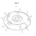
FIG. 2 is a perspective view showing the appearance of a mobile robot according to an embodiment; -
FIG. 3 is a perspective view showing the appearance of a beacon according to an embodiment; -
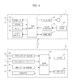
FIG. 4 is a control block diagram of a mobile robot system according to an embodiment; -
FIG. 5 is a conceptual diagram explaining the principle of the operation of a mobile robot system according to an embodiment; -
FIG. 6 is a flowchart illustrating a method of restricting a traveling region of a mobile robot in a mobile robot system according to an embodiment; -
FIG. 7 is a flowchart illustrating a method of preventing collision of a mobile robot in a mobile robot system according to an embodiment; -
FIG. 8 is a conceptual diagram explaining the principle of operation of a mobile robot system according to an embodiment; -
FIG. 9 is a flowchart illustrating a method of guiding a mobile robot to move to another region in a mobile robot system according to an embodiment; and -
FIG. 10 is a table showing signal transmission of a mobile robot according to a beacon setting state in a mobile robot system according to an embodiment. - Reference will now be made in detail to the embodiments, examples of which are illustrated in the accompanying drawings, wherein like reference numerals refer to the like elements throughout. The embodiments are described below to explain the present invention by referring to the figures.
-
FIG. 1 is a view showing the overall configuration of a mobile robot system according to an embodiment. The mobile robot system includes amobile robot 10 to perform a cleaning operation while autonomously traveling in a predetermined region and to transmit an infrared ray (IR) signal in packet units, and abeacon 20 separated from themobile robot 10 to receive the signal transmitted from themobile robot 10. - The
beacon 20 is movably mounted at a border (for example, a corner between a living room and a kitchen, a door between rooms, or the like) of a traveling region in order to restrict a traveling region of themobile robot 10. Thebeacon 20 detects a signal transmitted from themobile robot 10 and omnidirectionally transmits a response signal according to the detected result to themobile robot 10 so as to control avoidance navigation such that themobile robot 10 is prevented from crossing the border (confinement border) of the traveling region and themobile robot 10 is prevented from colliding with thebeacon 20. - In addition, the
beacon 20 has a lighthouse function to lead themobile robot 10 to another room such that the mobile robot performs a cleaning operation of another room after finishing a cleaning operation of one room. -
FIG. 2 is a perspective view showing the appearance of a mobile robot according to an embodiment. - In
FIG. 2 , themobile robot 10 includes amain body 12 forming the appearance thereof and a pair ofwheels 14 mounted under themain body 12 at a predetermined interval to drive themobile robot 10. The pair of drivingwheels 14 is selectively driven by a driving unit (motor) rotating the wheels such that themobile robot 10 travels in a desired direction. A plurality of auxiliary wheels to support themain body 12 and to smoothly travel themobile robot 10 may be mounted on the front and rear sides of the drivingwheels 14. - In addition, the
mobile robot 10 includes onetransmitter 100 to transmit an IR signal in packet units in order to report that the mobile robot travels, and a plurality (e.g., five) ofreceivers 102 to receive the response signal of thebeacon 20. Thetransmitter 100 is mounted on the upper side of the front surface of themain body 12 and uses a 360-degree spread lens to transmit the IR signal omnidirectionally (over 360 degrees). The plurality ofreceivers 102 is mounted on the front surface and the side surface of themain body 12 at a predetermined interval and uses a 180-degree spread lens to receive the IR signal omnidirectionally. -
FIG. 3 is a perspective view showing the appearance of a beacon according to an embodiment. InFIG. 3 , thebeacon 20 includes amain body 22 forming the appearance thereof, and asensor window 24 mounted on the circumference of themain body 22 to transmit or receive a signal. The outer wall of thesensor window 24 has a circular shape such that the beam of the transmitted or received signal is not bent. - In addition, the
beacon 20 includes afirst directivity receiver 200 to receive a signal (high/medium/low/approach signal) transmitted while themobile robot 10 travels in order to perform cleaning of one room within a restricted Field-Of-View (FOV) and to sense whether themobile robot 10 has entered a border (confinement border) of a traveling region,second directivity receivers 202 to receive a signal indicating that the cleaning of one room has been completed within the restricted FOV and to sense whether themobile robot 10 has approached a guide region to guide themobile robot 10 from one room to another room, anomnidirectional receiver 204 to receive an "approach" signal transmitted from themobile robot 10 and to sense whether themobile robot 10 has approached the vicinity of thebeacon 20, and a plurality (e.g., three) oftransmitters 206 to omnidirectionally transmit a response signal (an IR signal which is transmitted in order to prevent the mobile robot from crossing the confinement border or guide the mobile robot to another region) according to the detected result to themobile robot 10. - The
first directivity receiver 200 is a directivity reception slit for a confinement border recognition mode, which is mounted on the upper side of the front surface of thebeacon 20 so as to restrict a region to receive the signal (high/medium/low/approach) signal transmitted while themobile robot 10 performs cleaning of one room. The directivity reception slit for the confinement border recognition mode has directivity by restricting a signal reception region using a gap (width), a length and a height thereof. - Each of the
second directivity receivers 202 is a directivity reception slit for a movement mode, which is mounted on the left or right side of thefirst directivity receiver 200 so as to restrict a region to receive a signal indicating that the cleaning of one room has been completed from themobile robot 10. The directivity reception slit for the movement mode has directivity by restricting a signal reception region using a gap (width), a length and a height thereof, similar to the directivity reception slit for the confinement border recognition mode corresponding to thefirst directivity receiver 200. The width of the directivity reception slit for the movement mode corresponding to thesecond directivity receiver 202 is greater than that of the directivity reception slit for the confinement border recognition mode in order to lead themobile robot 10 from one room to another room. - The plurality (e.g., two) of
second directivity receivers 202 is mounted on the left and right sides of thefirst directivity receiver 200 so as to guide themobile robot 10 from a right reception region to a left reception region or from a left reception region to a right reception region when themobile robot 10 moves from one room to another room. - The
omnidirectional receiver 204 is an omnidirectional receiver provided on the central portion of the lower side of thebeacon 20 so as to receive an "approach" signal transmitted from themobile robot 10 over 360 degrees. Theomnidirectional receiver 204 receives the IR signal from any given direction using the refractive and reflective properties of alens 204a through areception module 204b and generates a spread light region. - The first and
second directivity receivers omnidirectional receiver 204 use a remote controller reception module with very low current consumption of a maximum of about 0.4 to 2.0 mA. - The plurality of
transmitters 206 transmits a response signal to report a reception direction and a reception signal to themobile robot 10 when the first andsecond directivity receivers omnidirectional receiver 204 receive the signal transmitted from themobile robot 100, and uses the 180-degree spread lens. - The
beacon 20 further includes abattery 26 to supply driving power of thebeacon 20, asignal setting switch 28 to set a signal arrival distance of thebeacon 20 to "high", "medium" or "low", and amode setting switch 30 to set an operation mode of thebeacon 20 to the "confinement border recognition mode" or the "movement mode". - If the
signal setting switch 28 is set to "high", the signal arrival distance of thebeacon 20 is about 4 m, which corresponds to 1/2 of that of a living room of a general home. - If the
signal setting switch 28 is set to "medium", the signal arrival distance of thebeacon 20 is about 2 m, which corresponds to that of a hallway of a kitchen in a general home. - If the
signal setting switch 28 is set to "low", the signal arrival distance of thebeacon 20 is about 1 m, which corresponds to the width of a door in a general home. -
FIG. 4 is a control block diagram of a mobile robot system according to an embodiment. - In
FIG. 4 , themobile robot 10 further includes aninput unit 104, anobstacle sensing unit 106, adriving unit 108, abattery sensing unit 110, astorage unit 112, and a robot control unit 114, in addition to the basic configuration ofFIG. 2 . - The
input unit 104 includes a plurality of buttons provided on the upper side of themain body 12 of the mobile robot or a remote controller (not shown) so as to enable a user to input a command to perform the operation of themobile robot 10. - The
obstacle sensing unit 106 senses obstacles such as furniture, office equipment or walls in a region in which themobile robot 10 travels. Theobstacle sensing unit 106 emits an ultrasonic signal to a path along which themobile robot 10 travels, receives the ultrasonic signal reflected from the obstacle, and senses presence/absence of the obstacle and a distance to the obstacle. At this time, theobstacle sensing unit 106 may be an IR sensor which includes a plurality of IR emitting elements and light receiving elements so as to emit IR and receive the reflected light. - The driving
unit 108 drives both drivingwheels 14 provided under themain body 12 of the mobile robot such that themobile robot 10 autonomously travels in the traveling region while changing the direction thereof, based on obstacle information sensed by theobstacle sensing unit 106, without collision with the wall or the obstacle. - The
battery sensing unit 110 senses a charging residual amount of a chargingbattery 109 to supply the driving power (e.g., energy necessary to transmit the signals by the plurality of transmitters) of themobile robot 10, and sends information about the charging residual amount to the robot control unit 114. - The
storage unit 112 is a memory to store an operating program to drive themobile robot 10, a traveling pattern, and location information of themobile robot 10 and obstacle information acquired in the traveling process. - The robot control unit 114 is a microprocessor to control the overall operation of the
mobile robot 10. The robot control unit 114 controls thetransmitter 100 to transmit the IR signal to report that themobile robot 10 travels in the packet units, and controls avoidance navigation of themobile robot 10 until the response signal is not received from thebeacon 20, if the plurality ofreceivers 102 receives the response signal from thebeacon 20. - In
FIG. 4 , thebeacon 20 further includes astorage unit 208 to store header information or the like of themobile robot 10 and abeacon control unit 210 to control the overall operation of thebeacon 20, that is, to control the plurality oftransmitters 206 to report that the first andsecond directivity receivers omnidirectional receiver 204 have received the signal transmitted from themobile robot 10 using the IR signal, in addition to the basic configuration shown inFIG. 3 . - Hereinafter, the operation and effects of the mobile robot system having the above-described configuration and the method of controlling the same will be described.
-
FIG. 5 is a conceptual diagram explaining the principle of the operation of a mobile robot system according to an embodiment, for example, when the operation mode of thebeacon 20 is set to a confinement border recognition mode. - In
FIG. 5 , themobile robot 10 autonomously travels in a traveling region (e.g., in a direction denoted by a thick arrow), and thebeacon 20 is provided at the border (e.g., a corner between a living room and a kitchen, a door between rooms, or the like) of the traveling region of themobile robot 10. - As shown in
FIG. 5 , themobile robot 10 transmits the IR signal to report that the mobile robot travels through onetransmitter 100 provided on the upper side of the front surface of themain body 12 of the robot in packet units while autonomously traveling in the traveling region. At this time, the packet signal transmitted from themobile robot 10 includes the header information of themobile robot 10 and signal data having an intensity of "high", "medium", "low", or "approach" to report that themobile robot 10 approaches. A packet signal transmission time is about 180 to 200 msec per cycle. - In the embodiment, if the
mobile robot 10 is located far from thebeacon 20, thebeacon 20 does not transmit the signal and thus the energy of thebeacon battery 26 is not unnecessarily wasted. At this time, thebeacon 20 is in a standby state in order to enable thefirst directivity receiver 200 and theomnidirectional receiver 204 to receive the signal transmitted from themobile robot 10 using standby power of the remote controller reception module with very low power consumption. - The
first directivity receiver 200 of thebeacon 20 restricts a confinement border in a slit shape such that the remote controller reception module has directivity, and senses that themobile robot 10 has approached the confinement border when the signal transmitted from themobile robot 10 enters the restricted confinement border. - The
omnidirectional receiver 204 of thebeacon 20 receives the signal transmitted from themobile robot 10 over 360 degrees and senses that themobile robot 10 has approached the vicinity of thebeacon 20 when the "approach" signal (the arrival distance of the "approach" signal indicates a distance by which the mobile robot is moved to the vicinity of the beacon enough to collide with the beacon) of the signals transmitted from themobile robot 10 is received. - If the
first directivity receiver 200 or theomindirectional receiver 204 of thebeacon 20 receives the signal transmitted from themobile robot 10, thebeacon 20 omnidirectionally transmits the response signal to themobile robot 10 to report that the signal of themobile robot 10 has been received through the plurality oftransmitters 206 such that themobile robot 10 is prevented from entering the border of the traveling region or themobile robot 10 is prevented from colliding with thebeacon 20. - Accordingly, the
mobile robot 10 receives the response signal of thebeacon 20 through the plurality ofreceivers 102 to stop traveling thereof and performs avoidance navigation such that themobile robot 10 is prevented from crossing the border of the traveling region or the mobile robot is prevented from colliding with thebeacon 20. -
FIG. 6 is a flowchart illustrating a method of restricting a traveling region of a mobile robot in a mobile robot system according to the embodiment. - In order to describe the operation, it is assumed that the
mode setting switch 30 of thebeacon 20 is set to the confinement border recognition mode. - In
FIG. 6 , themobile robot 10 transmits the IR signal to report that the mobile robot travels through thetransmitter 100 in packet units while traveling in the traveling region (300). - At this time, the
beacon 20 is in the standby state using standby power of the remote controller reception module with very low power consumption, and receives the signal transmitted from themobile robot 10 through thefirst directivity receiver 200 and transmits the received signal to thebeacon control unit 210, when the signal transmitted from themobile robot 10 enters the restricted FOV. - The
beacon control unit 210 determines whether thefirst directivity receiver 200 has received the signal transmitted from the mobile robot 10 (302). If thefirst directivity receiver 200 of thebeacon 20 has not received the signal transmitted from themobile robot 10, thebeacon 20 maintains the standby state (304). - If it is determined that the
first directivity receiver 200 of thebeacon 20 has received the signal transmitted from themobile robot 10 inOperation 302, thebeacon control unit 210 senses that themobile robot 10 has entered the confinement border and omnidirectionally transmits the response signal (IR signal) through the plurality oftransmitters 206 in order to report a "forbidden region" to the mobile robot 10 (306). - The
mobile robot 10 receives the response signal of thebeacon 20 through the plurality ofreceivers 102 and sends the response signal to the robot control unit 114. - The robot control unit 114 determines whether the plurality of
receivers 102 has received the response signal of the beacon 20 (308). If themobile robot 10 has not received the response signal of thebeacon 20, the method progresses toOperation 300 and the subsequent operations thereof are repeated. - If it is determined that the
mobile robot 10 has received the response signal of thebeacon 20 inOperation 308, the robot control unit 114 stops the cleaning navigation of themobile robot 10 and controls avoidance navigation such that themobile robot 10 rotates so as not to cross the confinement border (310). - Thereafter, the robot control unit 114 determines whether the response signal of the
beacon 20 is not sensed by the rotation avoidance navigation of the mobile robot 10 (312), and continues to perform rotation avoidance navigation of themobile robot 10 until the response signal of thebeacon 20 is not sensed, if the response signal of thebeacon 20 is sensed. - If it is determined that the response signal of the
beacon 20 is not sensed inOperation 312, the rotation avoidance navigation of themobile robot 10 is finished and cleaning navigation of the mobile robot is started in a direction in which the rotation is finished (314). -
FIG. 7 is a flowchart illustrating a method of preventing collision of a mobile robot in a mobile robot system according to an embodiment. - In order to describe the operation, it is assumed that the
mode setting switch 30 of thebeacon 20 is set to the confinement border recognition mode. - In
FIG. 7 , themobile robot 10 transmits the IR signal to report that the mobile robot travels through thetransmitter 100 in packet units while traveling in the traveling region (400). - At this time, the
beacon 20 is in the standby state using standby power of the remote controller reception module with very low power consumption, and receives the "approach" signal transmitted from themobile robot 10 through theomnidirectional receiver 204 and transmits the received signal to thebeacon control unit 210. - The
beacon control unit 210 determines whether theomnidirectional receiver 204 has received the signal transmitted from the mobile robot 10 (402). If theomnidirectional receiver 204 of thebeacon 20 has not received the "approach" signal transmitted from themobile robot 10, thebeacon 20 maintains the standby state (404). - If it is determined that the
directivity receiver 200 of thebeacon 20 has received the "approach" signal transmitted from themobile robot 10 inOperation 402, thebeacon control unit 210 senses that themobile robot 10 has approached the vicinity of thebeacon 20 and omnidirectionally transmits the response signal (IR signal) through the plurality oftransmitters 206 in order to report a "forbidden region" to the mobile robot 10 (406). - The
mobile robot 10 receives the response signal of thebeacon 20 through the plurality ofreceivers 102 and sends the response signal to the robot control unit 114. - The robot control unit 114 determines whether the plurality of
receivers 102 has received the response signal of the beacon 20 (408). If themobile robot 10 has not received the response signal of thebeacon 20, the method progresses toOperation 400 and the subsequent operations thereof are repeated. - If it is determined that the
mobile robot 10 has received the response signal of thebeacon 20 inOperation 408, the robot control unit 114 stops cleaning navigation of themobile robot 10 and controls avoidance navigation such that themobile robot 10 rotates so as not to collide with the beacon 20 (410). - Thereafter, the robot control unit 114 determines whether the response signal of the
beacon 20 is not sensed by the rotation avoidance navigation of the mobile robot 10 (412), and continues to perform rotation avoidance navigation of themobile robot 10 in an opposite direction of the traveling direction until the response signal of thebeacon 20 is not sensed, if the response signal of thebeacon 20 is sensed. - If it is determined that the response signal of the
beacon 20 is not sensed inOperation 412, the rotation avoidance navigation of themobile robot 10 in the opposite direction of the traveling direction is finished and cleaning navigation is started in the opposite direction of the traveling direction (414). -
FIG. 8 is a conceptual diagram explaining the principle of the operation of a mobile robot system according to an embodiment, for example, when the operation mode of thebeacon 20 is set to a movement mode. - In
FIG. 8 , themobile robot 10 travels along a guide region and thebeacon 20 is mounted between a border (e.g., a door between rooms) of a traveling region of themobile robot 10. - As shown in
FIG. 8 , themobile robot 10 transmits an IR signal to report that cleaning is completed over 360 degrees through thetransmitter 100 provided on the upper side of the front surface of themain body 12 of the robot, if themobile robot 10 completes cleaning of one room. - The
second directivity receiver 202 of thebeacon 20 restricts a left or right FOV (guide region) in a slit shape such that the remote controller reception module has directivity and senses that themobile robot 10 has entered the guide region when the signal transmitted from themobile robot 10 enters the restricted left or right FOV (guide region). - The
omnidirectional receiver 204 of thebeacon 20 receives the signal transmitted from themobile robot 10 over 360 degrees and senses that themobile robot 10 has approached the vicinity of thebeacon 20 when the "approach" signal transmitted from themobile robot 10 is received. - In the case where the
second directivity receiver 202 or theomnidirectional receiver 204 of thebeacon 20 senses the signal transmitted from themobile robot 10, thebeacon 20 omnidiectionally transmits a response to report that the signal of themobile robot 10 has been received through the plurality oftransmitters 206 such that themobile robot 10 approaches thebeacon 20 along the guide region formed by thebeacon 20 so as to move from one room to another room or themobile robot 10 performs wall-following navigation along an approach region (halo FOV) when the mobile robot senses the "approach" signal. - Accordingly, the
mobile robot 10 receives the response signal of thebeacon 20 through the plurality ofreceivers 102, approaches thebeacon 20 along the guide region, and performs wall-following navigation along the approach region (halo FOV) of thebeacon 20 when approaching the approach region (halo FOV) of thebeacon 20 so as not to cross the confinement border. - Although, in
FIG. 8 , the case were themobile robot 10 approaches thebeacon 20 along the right guide region, performs wall-following navigation along the approach region of thebeacon 20 after approaching the approach region of thebeacon 20, and moves from the right room to the left room is described, the embodiments are not limited thereto. Themobile robot 10 may approach thebeacon 20 along the left guide region, perform wall-following navigation along the approach region of thebeacon 20 after approaching the approach region of thebeacon 20, and move from the left room to the right room. -
FIG. 9 is a flowchart illustrating a method of guiding a mobile robot to another region in a mobile robot system according to an embodiment. - In order to describe the operation, it is assumed that the
mode setting switch 30 of thebeacon 20 is set to the movement mode. - In
FIG. 9 , themobile robot 10 transmits the IR signal for the movement mode to report that cleaning has been completed over 360 degrees through thetransmitter 100, if cleaning of one room is completed (500). - At this time, the
beacon 20 is in the standby state using standby power of the remote controller reception module with very low power consumption, and receives the signal transmitted from themobile robot 10 through thesecond directivity receiver 202 and transmits the received signal to thebeacon control unit 210, when the signal for the movement mode transmitted from themobile robot 10 enters the restricted left or right FOV. - Accordingly, the
beacon control unit 210 determines whether thesecond directivity receiver 202 has received the signal transmitted from the mobile robot 10 (502). If thesecond directivity receiver 202 of thebeacon 20 has not received the signal transmitted from themobile robot 10, thebeacon 20 maintains the standby state (504). - If it is determined that the
second directivity receiver 202 of thebeacon 20 has received the signal transmitted from themobile robot 10 inOperation 502, thebeacon control unit 210 senses that themobile robot 10 has entered the restricted left or right FOV (guide region) and omnidirectionally transmits the response signal (IR signal) through the plurality oftransmitters 206 in order to report the "guide region" to the mobile robot 10 (506). - The
mobile robot 10 receives the response signal of thebeacon 20 through the plurality ofreceivers 102 and sends the response signal to the robot control unit 114. - The robot control unit 114 determines whether the plurality of
receivers 102 has received the response signal of the beacon 20 (508). If themobile robot 10 has not received the response signal of thebeacon 20, the method progresses toOperation 500 and the subsequent operations thereof are repeated. - If it is determined that the
mobile robot 10 has received the response signal of thebeacon 20 inOperation 508, the robot control unit 114 controls guide navigation such that themobile robot 10 approaches thebeacon 20 along the guide region formed by thebeacon 20 so as to move from one room of which cleaning has completed to another room (510). - Thereafter, the
beacon control unit 210 determines whether theomnidirectional receiver 204 has received the "approach" signal transmitted from themobile robot 10, while guide navigation is performed such that themobile robot 10 approaches the approach region (halo FOV) of the beacon 20 (512). - If it is determined that the
omnidirectional receiver 204 of thebeacon 20 has not received the "approach" signal transmitted from themobile robot 10 inOperation 512, the method progresses toOperation 510 and thebeacon 20 continues to perform the guide navigation of themobile robot 10. - If it is determined that the
omnidirectional receiver 204 of thebeacon 20 has received the "approach" signal transmitted from themobile robot 10 inOperation 512, thebeacon control unit 210 senses that themobile robot 10 has approached the approach region (halo FOV) of thebeacon 20, and thebeacon 20 ommidirectionally transmits a response signal to report that the "approach" signal of themobile robot 10 has been received through the plurality oftransmitters 206. - Then, the
mobile robot 10 receives the response signal of thebeacon 20 through the plurality ofreceivers 102 and controls wall-following navigation so as to cross the confinement border along the approach region (halo FOV) of the beacon 20 (514). - Thereafter, the robot control unit 114 determines whether the
mobile robot 10 has crossed the confinement border along the approach region (halo FOV) (516), and the method progresses toOperation 514 so as to continue to perform wall-following navigation such that the mobile robot crosses the confinement border along the approach region (halo FOV) if themobile robot 10 has not crossed the confinement border. - If it is determined that the
mobile robot 10 has crossed the confinement border inOperation 516, the navigation of themobile robot 10 is controlled through the other guide region (the left guide region if the mobile robot moves from the right room to the left room along the right guide region) (518). - In the control of the navigation of the
mobile robot 10 through the other guide region, themobile robot 10 continues to perform wall-following along the approach region (halo FOV) until the second directivity receiver 202 (more particularly, the second directivity receiver shown on the left side ofFIG. 5 ) of thebeacon 20 receives the signal transmitted from themobile robot 10 is received after themobile robot 10 crosses the confinement border and, when thesecond directivity receiver 202 of thebeacon 20 receives the signal transmitted from themobile robot 10, it is sensed that themobile robot 10 has entered the left reception region (guide region) and themobile robot 10 is controlled to start the cleaning navigation of the left room (that is, another room) on the basis of the left guide region (that is, the other guide region). -
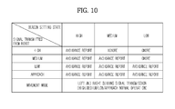
FIG. 10 is a table showing signal transmission of a mobile robot according to a beacon setting state in a mobile robot system according to an embodiment. - In
FIG. 10 , the user operates thesignal setting switch 28 of thebeacon 20 so as to set the arrival distance of thebeacon 20 to "high", "medium" or "low". Then, even when thebeacon 20 receives the signal transmitted from themobile robot 10, thebeacon 20 does not transmit the response signal according to the set value such that the avoidance navigation of themobile robot 10 may be differently controlled. - For example, if the user sets the
signal setting switch 28 of thebeacon 20 to "low", even when thefirst directivity receiver 200 of thebeacon 20 receives the signal transmitted from themobile robot 10, thebeacon 20 does not omnidirectionally transmit the response signal such that themobile robot 10 ignores avoidance navigation with respect to the signal with the intensity of "high" or "medium" of the signals transmitted from themobile robot 10, and reports avoidance navigation with respect to only the signal with the intensity of "low" or "approach" of the signals transmitted from themobile robot 10. - For example, if the user sets the
signal setting switch 28 of thebeacon 20 to "medium", even when thefirst directivity receiver 200 of thebeacon 20 receives the signal transmitted from themobile robot 10, thebeacon 20 does not omnidirectionally transmit the response signal such that themobile robot 10 ignores avoidance navigation with respect to the signal with the intensity of "high" of the signals transmitted from themobile robot 10, and reports avoidance navigation with respect to only the signal with the intensity of "medium", "low" or "approach" of the signals transmitted from themobile robot 10. - The above-described example indicates the case where the
first directivity receiver 200 of thebeacon 20 receives the signal transmitted from themobile robot 10 when themode setting switch 30 of thebeacon 20 is set to the "confinement border recognition mode". If the user sets themode setting switch 30 of thebeacon 20 to the "movement mode", thesecond directivity receiver 202 of thebeacon 20 receives the signal for the movement mode transmitted from themobile robot 10 to lead themobile robot 10 to another room through the left and right guide regions. - Although the signal transmitted from the
mobile robot 10 is the IR signal in the embodiments, the embodiments are not limited thereto. Even when a visible ray, an ultrasonic wave, or a laser signal is used, the same effects can be realized. - Although the signal transmitted from the
beacon 20 is the IR signal in the embodiments, the embodiments are not limited thereto. Even when a visible ray, an ultrasonic wave, a Radio Frequency (RF) signal or a laser signal is used, the same effects can be realized. -
- Embodiment 1: A mobile robot system comprising:
- a mobile robot to transmit a signal while traveling in a traveling region; and
- a beacon to receive the signal transmitted from the mobile robot and to transmit a response signal to the mobile robot,
wherein the beacon restricts a Field-of-View (FOV) to receive the signal and transmits the response signal to the mobile robot only when the signal transmitted from the mobile robot is sensed to be within the restricted FOV.
- Embodiment 2: The mobile robot system of embodiment 1, wherein:
- the mobile robot further includes one or more transmitters to transmit the signal to report a traveling state of the mobile robot, and
- the mobile robot comprises a main body and the transmitters are 360-degree spread lenses which are mounted on an upper side of a front surface of the main body of the mobile robot to transmit the signal in all directions in which the mobile robot travels.
- Embodiment 3: The mobile robot system of embodiment 1, wherein the mobile robot further includes:
- a receiver to receive the response signal of the beacon; and
- a robot control unit to control avoidance navigation of the mobile robot if the response signal of the beacon is received.
- Embodiment 4: The mobile robot system of embodiment 3, further comprising a plurality of the receivers, the mobile robot comprising a main body, and the receivers including 180-degree spread lenses which are mounted on a front surface and a side surface of a main body of the mobile robot at a predetermined interval to transmit and receive the signal in all directions in which the mobile robot travels.
- Embodiment 5: The mobile robot system of embodiment 1, wherein the beacon is mounted so as to be separated from the mobile robot.
- Embodiment 6: The mobile robot system of embodiment 5, wherein:
- the beacon further includes a directivity receiver to receive the signal transmitted from the mobile robot within the restricted FOV, and
- the directivity receiver is a slit-shaped remote controller reception module with a width, a length and a height to restrict the FOV.
- Embodiment 7: The mobile robot system of embodiment 6, wherein the directivity receiver includes a first directivity receiver to sense whether the mobile robot has approached a confinement border of the traveling region and a plurality of second directivity receivers to sense whether the mobile robot has crossed the confinement border and has approached a guide region so as to move to another region.
- Embodiment 8: The mobile robot system of
embodiment 7, wherein the beacon comprises a main body, and the first directivity receiver is a slit for a confinement border recognition mode, which is mounted on an upper side of a front surface of the main body of the beacon. - Embodiment 9: The mobile robot system of embodiment 8, wherein the second directivity receivers are slits for a movement mode, which are mounted on the left and right sides of the first directivity receiver.
- Embodiment 10: The mobile robot system of embodiment 5, wherein the beacon further includes an omnidirectional receiver to receive the signal transmitted from the mobile robot over 360 degrees and to sense whether the mobile robot has approached.
- Embodiment 11: A method of controlling a mobile robot system, the method comprising:
- at a mobile robot, transmitting a signal while traveling in a traveling region;
- determining whether the signal transmitted from the mobile robot is sensed within a restricted Field-of-View (FOV) of a beacon;
- at the beacon, transmitting a response signal to the mobile robot if the signal transmitted from the mobile robot is sensed within the restricted FOV; and
- restricting traveling of the mobile robot such that the mobile robot does not cross a confinement border of the traveling region when the mobile robot receives the response signal of the beacon.
- Embodiment 12: The method of embodiment 11, wherein the restricting of the traveling of the mobile robot includes controlling avoidance navigation of the mobile robot such that the mobile robot rotates until the response signal of the beacon is not received.
- Embodiment 13: A method of controlling a mobile robot system, the method comprising:
- at a mobile robot, transmitting a signal while traveling in a traveling region;
- at a beacon, receiving the signal transmitted from the mobile robot over 360 degrees and determining whether the mobile robot has approached the beacon;
- at the beacon, transmitting a response signal to the mobile robot if the mobile robot has approached the beacon; and
- at the mobile robot, performing avoidance navigation to prevent collision with the beacon when the mobile robot receives the response signal of the beacon.
- Embodiment 14: A method of controlling a mobile robot system, the method comprising:
- at a mobile robot, transmitting a signal when cleaning of a traveling region is completed;
- determining whether the signal transmitted from the mobile robot is sensed within a restricted Field-of-View (FOV) of a beacon;
- at the beacon, transmitting a response signal to the mobile robot if the signal transmitted from the mobile robot is sensed within the restricted FOV; and
- guiding the mobile robot to cross a confinement border of the traveling region and to move to another region when the mobile robot receives the response signal of the beacon.
- Embodiment 15: The method of
embodiment 14, wherein the guiding of the mobile robot includes:- enabling the mobile robot to approach the beacon along a guide region formed by the beacon;
- determining whether the mobile robot has approached an approach region of the beacon;
- at the beacon, transmitting the response signal to the mobile robot when the mobile robot has approached the approach region of the beacon; and
- at the mobile robot, performing wall-following navigation along the approach region of the beacon so as to cross the confinement border, if the mobile robot receives the response signal of the beacon.
Claims (13)
- A mobile robot system characterized in that it comprise
a mobile robot (10) to transmit a signal while traveling in a traveling region; and
a beacon (20) to receive the signal transmitted from the mobile robot over 360 degrees and to transmit a response signal to the mobile robot,
wherein the beacon is adapted to transmit the response signal to the mobile robot when the mobile robot has approached the beacon; and
wherein the mobile robot is adapted to perform avoidance navigation to prevent collision with the beacon when the mobile robot receives the response signal from the beacon. - The mobile robot system according to claim 1, wherein:the mobile robot further includes one or more transmitters (100) to transmit an IR signal in order to report that the mobile robot travels, andthe mobile robot comprises a main body (12) and the transmitters are 360-degree spread lenses which are mounted on an upper side of a front surface of the main body of the mobile robot to transmit the signal in all directions in which the mobile robot travels.
- The mobile robot system according to claim 1, wherein the mobile robot further includes:a receiver (102) to receive the response signal of the beacon; anda robot control unit (114) adapted to control avoidance navigation of the mobile robot if the response signal of the beacon is received.
- The mobile robot system according to claim 3, further comprising a plurality of the receivers, the mobile robot comprising a main body, and the receivers including 180-degree spread lenses which are mounted on a front surface and a side surface of a main body of the mobile robot at a predetermined interval to transmit and receive the signal in all directions in which the mobile robot travels.
- The mobile robot system according to claim 1, wherein the beacon is mounted so as to be separated from the mobile robot.
- The mobile robot system according to claim 5, wherein:the beacon further includes a directivity receiver to receive the signal transmitted from the mobile robot within the restricted FOV, andthe directivity receiver is a slit-shaped remote controller reception module with a width, a length and a height to restrict the FOV.
- The mobile robot system according to claim 6, wherein the directivity receiver includes a first directivity receiver (200) to sense whether the mobile robot has approached a confinement border of the traveling region and a plurality of second directivity receivers (202) to sense whether the mobile robot has crossed the confinement border and has approached a guide region so as to move to another region.
- The mobile robot system according to claim 7, wherein the beacon comprises a main body (22), and the first directivity receiver is a slit for a confinement border recognition mode, which is mounted on an upper side of a front surface of the main body of the beacon.
- The mobile robot system according to claim 8, wherein the second directivity receivers are slits for a movement mode, which are mounted on the left and right sides of the first directivity receiver.
- The mobile robot system according to claim 5, wherein the beacon further includes an omnidirectional receiver (204) to receive the signal transmitted from the mobile robot over 360 degrees and to sense whether the mobile robot has approached.
- A method of controlling a mobile robot system, the method comprising:at a mobile robot, transmitting a signal while traveling in a traveling region;at a beacon, receiving the signal transmitted from the mobile robot over 360 degrees and determining whether the mobile robot has approached the beacon;at the beacon, transmitting a response signal to the mobile robot if the mobile robot has approached the beacon; andat the mobile robot, performing avoidance navigation to prevent collision with the beacon when the mobile robot receives the response signal of the beacon.
- The method according to claim 11, further comprising:at a mobile robot, transmitting a signal while traveling in a traveling region;determining whether the signal transmitted from the mobile robot is sensed within a restricted Field-of-View (FOV) of a beacon;at the beacon, transmitting a response signal to the mobile robot if the signal transmitted from the mobile robot is sensed within the restricted FOV; andrestricting traveling of the mobile robot such that the mobile robot does not cross a confinement border of the traveling region when the mobile robot receives the response signal of the beacon.
- The method according to claim 12, wherein the restricting of the traveling of the mobile robot includes controlling avoidance navigation of the mobile robot such that the mobile robot rotates until the response signal of the beacon is not received.
Applications Claiming Priority (3)
| Application Number | Priority Date | Filing Date | Title |
|---|---|---|---|
| KR20090042784 | 2009-05-15 | ||
| KR20090101527A KR101487781B1 (en) | 2009-05-15 | 2009-10-26 | Mobile robot system and control method thereof |
| EP10161934A EP2256572B1 (en) | 2009-05-15 | 2010-05-05 | Mobile robot system and improved method of working space confinement |
Related Parent Applications (2)
| Application Number | Title | Priority Date | Filing Date |
|---|---|---|---|
| EP10161934.4 Division | 2010-05-05 | ||
| EP10161934A Division EP2256572B1 (en) | 2009-05-15 | 2010-05-05 | Mobile robot system and improved method of working space confinement |
Publications (2)
| Publication Number | Publication Date |
|---|---|
| EP2581797A1 true EP2581797A1 (en) | 2013-04-17 |
| EP2581797B1 EP2581797B1 (en) | 2021-08-18 |
Family
ID=42380500
Family Applications (2)
| Application Number | Title | Priority Date | Filing Date |
|---|---|---|---|
| EP13151003.4A Active EP2581797B1 (en) | 2009-05-15 | 2010-05-05 | Beacon collision avoidance method for a mobile robot system |
| EP10161934A Active EP2256572B1 (en) | 2009-05-15 | 2010-05-05 | Mobile robot system and improved method of working space confinement |
Family Applications After (1)
| Application Number | Title | Priority Date | Filing Date |
|---|---|---|---|
| EP10161934A Active EP2256572B1 (en) | 2009-05-15 | 2010-05-05 | Mobile robot system and improved method of working space confinement |
Country Status (2)
| Country | Link |
|---|---|
| US (2) | US8688272B2 (en) |
| EP (2) | EP2581797B1 (en) |
Families Citing this family (37)
| Publication number | Priority date | Publication date | Assignee | Title |
|---|---|---|---|---|
| US7706917B1 (en) | 2004-07-07 | 2010-04-27 | Irobot Corporation | Celestial navigation system for an autonomous robot |
| US11209833B2 (en) * | 2004-07-07 | 2021-12-28 | Irobot Corporation | Celestial navigation system for an autonomous vehicle |
| EP2581797B1 (en) * | 2009-05-15 | 2021-08-18 | Samsung Electronics Co., Ltd. | Beacon collision avoidance method for a mobile robot system |
| CN102156473A (en) * | 2010-12-16 | 2011-08-17 | 深圳市银星智能电器有限公司 | Restricting system for mobile robot |
| TW201240636A (en) * | 2011-04-11 | 2012-10-16 | Micro Star Int Co Ltd | Cleaning system |
| US20130215721A1 (en) * | 2012-02-21 | 2013-08-22 | Gary Li | Positioning system for detecting position of cleansing device |
| KR101954144B1 (en) | 2012-06-08 | 2019-03-05 | 엘지전자 주식회사 | Robot cleaner, controlling method of the same, and robot cleaning system |
| CN102914967B (en) * | 2012-09-21 | 2015-01-28 | 浙江工业大学 | Autonomous navigation and man-machine coordination picking operating system of picking robot |
| USD733203S1 (en) * | 2013-12-17 | 2015-06-30 | Roambotics Inc. | Personal robot |
| WO2015094052A1 (en) | 2013-12-19 | 2015-06-25 | Husqvarna Ab | Obstacle detection for a robotic working tool |
| KR102412747B1 (en) | 2014-02-28 | 2022-06-27 | 삼성전자주식회사 | Cleaning robot and remote controller therein |
| TWI533101B (en) * | 2015-01-23 | 2016-05-11 | cheng-xiang Yan | System and Method of Restricting Robot Action |
| US20160229059A1 (en) * | 2015-02-08 | 2016-08-11 | AI Incorporated | Robot Repelling System and Method for Repelling a Robotic Device |
| USD765750S1 (en) * | 2015-02-27 | 2016-09-06 | Kenneth C. Miller | Robot |
| KR102388448B1 (en) * | 2015-06-09 | 2022-04-21 | 삼성전자주식회사 | Moving robot and controlling method thereof |
| CN105108728A (en) * | 2015-09-17 | 2015-12-02 | 国网山东省电力公司德州供电公司 | Inspection robot special for cable trenches of substations |
| JP2017064065A (en) * | 2015-09-30 | 2017-04-06 | 東芝ライフスタイル株式会社 | Beacon device and travel body device |
| CN105759814B (en) * | 2016-01-27 | 2020-02-14 | 深圳市银星智能科技股份有限公司 | Restriction device of robot and restriction system and method |
| US11829148B1 (en) * | 2016-03-03 | 2023-11-28 | AI Incorporated | Cleaning robot and operation thereof |
| JP6235640B2 (en) * | 2016-03-18 | 2017-11-22 | 本田技研工業株式会社 | Unmanned work vehicle |
| JP6243944B2 (en) * | 2016-03-18 | 2017-12-06 | 本田技研工業株式会社 | Unmanned work vehicle |
| CN105689345B (en) * | 2016-03-22 | 2018-09-25 | 深圳市百事达卓越科技股份有限公司 | Explosion prevention robot for cleaning the storage and Oilcan cleaning work station |
| US10486303B2 (en) | 2016-05-24 | 2019-11-26 | Bruce Donald Westermo | Elevated robotic assistive device system and method |
| US9868214B2 (en) * | 2016-06-20 | 2018-01-16 | X Development Llc | Localization of a mobile system |
| USD846536S1 (en) * | 2017-03-15 | 2019-04-23 | Al Incorporated | Robot confinement transceiver |
| CN108988403A (en) * | 2017-05-31 | 2018-12-11 | 北京小米移动软件有限公司 | Recharging system, autonomous mobile apparatus and charging pile |
| CN107186728B (en) * | 2017-06-15 | 2020-02-14 | 重庆柚瓣家科技有限公司 | Intelligent endowment service robot control system |
| WO2019104738A1 (en) * | 2017-12-01 | 2019-06-06 | 深圳市沃特沃德股份有限公司 | Restricting device, visual sweeping robot and control method therefor |
| CN107803837B (en) * | 2017-12-01 | 2020-02-07 | 深圳市无限动力发展有限公司 | Restricting device, visual floor sweeping robot and control method of visual floor sweeping robot |
| USD879852S1 (en) * | 2018-03-15 | 2020-03-31 | Beijing Geekplus Technology Co., Ltd. | Mobile robot |
| USD875088S1 (en) * | 2018-04-17 | 2020-02-11 | Taoglas Group Holdings Limited | Bracket antenna module |
| USD897386S1 (en) * | 2018-05-04 | 2020-09-29 | Beijing Ling Technology Co., Ltd. | Picture-book reading robot |
| US11435759B2 (en) * | 2018-05-04 | 2022-09-06 | Lg Electronics Inc. | Plurality of autonomous mobile robots and controlling method for the same |
| CN211933894U (en) | 2018-08-01 | 2020-11-17 | 尚科宁家运营有限公司 | Robot vacuum cleaner |
| EP3871206A4 (en) * | 2018-10-22 | 2021-12-22 | Lazer Safe Pty Ltd | Wireless monitoring/control |
| CN110597255B (en) * | 2019-09-11 | 2022-08-09 | 珠海一微半导体股份有限公司 | Method for establishing safety zone by using seat avoidance signal |
| USD923070S1 (en) * | 2019-12-23 | 2021-06-22 | Lg Electronics Inc. | Robot ultraviolet sterilizer |
Citations (2)
| Publication number | Priority date | Publication date | Assignee | Title |
|---|---|---|---|---|
| US20070244610A1 (en) * | 2005-12-02 | 2007-10-18 | Ozick Daniel N | Autonomous coverage robot navigation system |
| US20080051953A1 (en) * | 2001-01-24 | 2008-02-28 | Irobot Corporation | Robot navigation |
Family Cites Families (21)
| Publication number | Priority date | Publication date | Assignee | Title |
|---|---|---|---|---|
| US6040801A (en) * | 1964-04-30 | 2000-03-21 | The United States Of America As Represented By The Secretary Of The Navy | Low duty cycle navigation system |
| SE502834C2 (en) * | 1994-03-29 | 1996-01-29 | Electrolux Ab | Method and apparatus for detecting obstacles in self-propelled apparatus |
| JP3296105B2 (en) * | 1994-08-26 | 2002-06-24 | ミノルタ株式会社 | Autonomous mobile robot |
| WO1998004388A1 (en) * | 1996-07-25 | 1998-02-05 | Honda Giken Kogyo Kabushiki Kaisha | Gait generating device for leg type moving robot |
| AU2003262893A1 (en) * | 2002-08-21 | 2004-03-11 | Neal Solomon | Organizing groups of self-configurable mobile robotic agents |
| US7054716B2 (en) * | 2002-09-06 | 2006-05-30 | Royal Appliance Mfg. Co. | Sentry robot system |
| US7133746B2 (en) * | 2003-07-11 | 2006-11-07 | F Robotics Acquistions, Ltd. | Autonomous machine for docking with a docking station and method for docking |
| KR100480144B1 (en) * | 2003-07-23 | 2005-04-07 | 엘지전자 주식회사 | Position detection apparatus and method for mobile robot |
| KR100548272B1 (en) * | 2003-07-23 | 2006-02-02 | 엘지전자 주식회사 | Position detection apparatus and method for mobile robot |
| KR100565227B1 (en) * | 2003-12-22 | 2006-03-30 | 엘지전자 주식회사 | Position recognition apparatus and method for mobile robot |
| TWI258259B (en) * | 2004-04-20 | 2006-07-11 | Jason Yan | Automatic charging system of mobile robotic electronic device |
| KR100641113B1 (en) * | 2004-07-30 | 2006-11-02 | 엘지전자 주식회사 | Mobile robot and his moving control method |
| KR100696134B1 (en) * | 2005-04-25 | 2007-03-22 | 엘지전자 주식회사 | System for computing Location of a moving robot, and system for going the moving robot to charging equipment using the computing location and method thereof |
| KR100645817B1 (en) | 2005-07-22 | 2006-11-23 | 엘지전자 주식회사 | Virtual wall system of moving robot and method thereof |
| EP2544066B1 (en) * | 2005-12-02 | 2018-10-17 | iRobot Corporation | Robot system |
| US20070271011A1 (en) * | 2006-05-12 | 2007-11-22 | Samsung Electronics Co., Ltd. | Indoor map building apparatus, method, and medium for mobile robot |
| US8417383B2 (en) * | 2006-05-31 | 2013-04-09 | Irobot Corporation | Detecting robot stasis |
| KR100794728B1 (en) | 2006-08-11 | 2008-01-15 | 주식회사 나인티시스템 | System and method of measuring robot in localization |
| CA2591808A1 (en) * | 2007-07-11 | 2009-01-11 | Hsien-Hsiang Chiu | Intelligent object tracking and gestures sensing input device |
| WO2009007983A2 (en) * | 2007-07-12 | 2009-01-15 | Carmel - Haifa University Economic Corp Ltd. | Localization method for mobile robots based on landmarks |
| EP2581797B1 (en) * | 2009-05-15 | 2021-08-18 | Samsung Electronics Co., Ltd. | Beacon collision avoidance method for a mobile robot system |
-
2010
- 2010-05-05 EP EP13151003.4A patent/EP2581797B1/en active Active
- 2010-05-05 EP EP10161934A patent/EP2256572B1/en active Active
- 2010-05-12 US US12/662,942 patent/US8688272B2/en active Active
-
2014
- 2014-02-10 US US14/176,319 patent/US9314925B2/en active Active
Patent Citations (2)
| Publication number | Priority date | Publication date | Assignee | Title |
|---|---|---|---|---|
| US20080051953A1 (en) * | 2001-01-24 | 2008-02-28 | Irobot Corporation | Robot navigation |
| US20070244610A1 (en) * | 2005-12-02 | 2007-10-18 | Ozick Daniel N | Autonomous coverage robot navigation system |
Also Published As
| Publication number | Publication date |
|---|---|
| US20140156071A1 (en) | 2014-06-05 |
| US20100292839A1 (en) | 2010-11-18 |
| US9314925B2 (en) | 2016-04-19 |
| EP2256572A1 (en) | 2010-12-01 |
| US8688272B2 (en) | 2014-04-01 |
| EP2256572B1 (en) | 2013-01-16 |
| EP2581797B1 (en) | 2021-08-18 |
Similar Documents
| Publication | Publication Date | Title |
|---|---|---|
| US9314925B2 (en) | Mobile robot system and method of controlling the same | |
| CN102048499B (en) | Mobile robot system and control method thereof | |
| EP3599962B1 (en) | Cleaner and method of controlling the same | |
| JP6539699B2 (en) | Autonomous coverage robot navigation system | |
| US9958871B2 (en) | Robot confinement | |
| EP3087894B1 (en) | Moving robot and controlling method thereof | |
| EP3054361B1 (en) | Apparatus and method for returning of a robot to a charging station | |
| EP1331537B1 (en) | Method and system for robot localization and confinement of workspace | |
| US11148290B2 (en) | Plurality of robot cleaner and a controlling method for the same | |
| JP5396577B2 (en) | Operating system | |
| US11832782B2 (en) | Vacuum cleaner and method for controlling same | |
| JP2009518715A (en) | Autonomous coverage robot navigation system | |
| KR101487781B1 (en) | Mobile robot system and control method thereof | |
| JP4962255B2 (en) | Self-propelled device | |
| JP4910972B2 (en) | Self-propelled device and program |
Legal Events
| Date | Code | Title | Description |
|---|---|---|---|
| PUAI | Public reference made under article 153(3) epc to a published international application that has entered the european phase |
Free format text: ORIGINAL CODE: 0009012 |
|
| AC | Divisional application: reference to earlier application |
Ref document number: 2256572 Country of ref document: EP Kind code of ref document: P |
|
| AK | Designated contracting states |
Kind code of ref document: A1 Designated state(s): AL AT BE BG CH CY CZ DE DK EE ES FI FR GB GR HR HU IE IS IT LI LT LU LV MC MK MT NL NO PL PT RO SE SI SK SM TR |
|
| 17P | Request for examination filed |
Effective date: 20131017 |
|
| RBV | Designated contracting states (corrected) |
Designated state(s): AL AT BE BG CH CY CZ DE DK EE ES FI FR GB GR HR HU IE IS IT LI LT LU LV MC MK MT NL NO PL PT RO SE SI SK SM TR |
|
| 17Q | First examination report despatched |
Effective date: 20131114 |
|
| REG | Reference to a national code |
Ref country code: DE Ref legal event code: R079 Ref document number: 602010067463 Country of ref document: DE Free format text: PREVIOUS MAIN CLASS: G05D0001020000 Ipc: B25J0005000000 |
|
| RIC1 | Information provided on ipc code assigned before grant |
Ipc: B25J 9/16 20060101ALI20160309BHEP Ipc: B25J 11/00 20060101ALI20160309BHEP Ipc: B25J 5/00 20060101AFI20160309BHEP Ipc: G05D 1/02 20060101ALI20160309BHEP Ipc: B25J 9/00 20060101ALI20160309BHEP |
|
| STAA | Information on the status of an ep patent application or granted ep patent |
Free format text: STATUS: EXAMINATION IS IN PROGRESS |
|
| APAZ | Date of receipt of statement of grounds of appeal deleted |
Free format text: ORIGINAL CODE: EPIDOSDNOA3E |
|
| APBK | Appeal reference recorded |
Free format text: ORIGINAL CODE: EPIDOSNREFNE |
|
| APBN | Date of receipt of notice of appeal recorded |
Free format text: ORIGINAL CODE: EPIDOSNNOA2E |
|
| APBR | Date of receipt of statement of grounds of appeal recorded |
Free format text: ORIGINAL CODE: EPIDOSNNOA3E |
|
| APBR | Date of receipt of statement of grounds of appeal recorded |
Free format text: ORIGINAL CODE: EPIDOSNNOA3E |
|
| APBV | Interlocutory revision of appeal recorded |
Free format text: ORIGINAL CODE: EPIDOSNIRAPE |
|
| APBK | Appeal reference recorded |
Free format text: ORIGINAL CODE: EPIDOSNREFNE |
|
| APBN | Date of receipt of notice of appeal recorded |
Free format text: ORIGINAL CODE: EPIDOSNNOA2E |
|
| APBR | Date of receipt of statement of grounds of appeal recorded |
Free format text: ORIGINAL CODE: EPIDOSNNOA3E |
|
| APAF | Appeal reference modified |
Free format text: ORIGINAL CODE: EPIDOSCREFNE |
|
| APBT | Appeal procedure closed |
Free format text: ORIGINAL CODE: EPIDOSNNOA9E |
|
| GRAP | Despatch of communication of intention to grant a patent |
Free format text: ORIGINAL CODE: EPIDOSNIGR1 |
|
| STAA | Information on the status of an ep patent application or granted ep patent |
Free format text: STATUS: GRANT OF PATENT IS INTENDED |
|
| INTG | Intention to grant announced |
Effective date: 20210311 |
|
| RIN1 | Information on inventor provided before grant (corrected) |
Inventor name: JANG, HWI CHAN Inventor name: JUNG, JAE YOUNG Inventor name: JOO, JAE MAN Inventor name: YOO, KYUNG HWAN Inventor name: KIM, DONG WON Inventor name: CHUNG, WOO RAM Inventor name: HONG, JUN PYO |
|
| GRAS | Grant fee paid |
Free format text: ORIGINAL CODE: EPIDOSNIGR3 |
|
| GRAA | (expected) grant |
Free format text: ORIGINAL CODE: 0009210 |
|
| STAA | Information on the status of an ep patent application or granted ep patent |
Free format text: STATUS: THE PATENT HAS BEEN GRANTED |
|
| AC | Divisional application: reference to earlier application |
Ref document number: 2256572 Country of ref document: EP Kind code of ref document: P |
|
| AK | Designated contracting states |
Kind code of ref document: B1 Designated state(s): AL AT BE BG CH CY CZ DE DK EE ES FI FR GB GR HR HU IE IS IT LI LT LU LV MC MK MT NL NO PL PT RO SE SI SK SM TR |
|
| REG | Reference to a national code |
Ref country code: GB Ref legal event code: FG4D |
|
| REG | Reference to a national code |
Ref country code: CH Ref legal event code: EP |
|
| REG | Reference to a national code |
Ref country code: DE Ref legal event code: R096 Ref document number: 602010067463 Country of ref document: DE |
|
| REG | Reference to a national code |
Ref country code: IE Ref legal event code: FG4D Ref country code: AT Ref legal event code: REF Ref document number: 1421200 Country of ref document: AT Kind code of ref document: T Effective date: 20210915 |
|
| REG | Reference to a national code |
Ref country code: LT Ref legal event code: MG9D |
|
| REG | Reference to a national code |
Ref country code: NL Ref legal event code: FP |
|
| REG | Reference to a national code |
Ref country code: AT Ref legal event code: MK05 Ref document number: 1421200 Country of ref document: AT Kind code of ref document: T Effective date: 20210818 |
|
| PG25 | Lapsed in a contracting state [announced via postgrant information from national office to epo] |
Ref country code: PT Free format text: LAPSE BECAUSE OF FAILURE TO SUBMIT A TRANSLATION OF THE DESCRIPTION OR TO PAY THE FEE WITHIN THE PRESCRIBED TIME-LIMIT Effective date: 20211220 Ref country code: NO Free format text: LAPSE BECAUSE OF FAILURE TO SUBMIT A TRANSLATION OF THE DESCRIPTION OR TO PAY THE FEE WITHIN THE PRESCRIBED TIME-LIMIT Effective date: 20211118 Ref country code: FI Free format text: LAPSE BECAUSE OF FAILURE TO SUBMIT A TRANSLATION OF THE DESCRIPTION OR TO PAY THE FEE WITHIN THE PRESCRIBED TIME-LIMIT Effective date: 20210818 Ref country code: ES Free format text: LAPSE BECAUSE OF FAILURE TO SUBMIT A TRANSLATION OF THE DESCRIPTION OR TO PAY THE FEE WITHIN THE PRESCRIBED TIME-LIMIT Effective date: 20210818 Ref country code: BG Free format text: LAPSE BECAUSE OF FAILURE TO SUBMIT A TRANSLATION OF THE DESCRIPTION OR TO PAY THE FEE WITHIN THE PRESCRIBED TIME-LIMIT Effective date: 20211118 Ref country code: AT Free format text: LAPSE BECAUSE OF FAILURE TO SUBMIT A TRANSLATION OF THE DESCRIPTION OR TO PAY THE FEE WITHIN THE PRESCRIBED TIME-LIMIT Effective date: 20210818 Ref country code: LT Free format text: LAPSE BECAUSE OF FAILURE TO SUBMIT A TRANSLATION OF THE DESCRIPTION OR TO PAY THE FEE WITHIN THE PRESCRIBED TIME-LIMIT Effective date: 20210818 Ref country code: HR Free format text: LAPSE BECAUSE OF FAILURE TO SUBMIT A TRANSLATION OF THE DESCRIPTION OR TO PAY THE FEE WITHIN THE PRESCRIBED TIME-LIMIT Effective date: 20210818 Ref country code: SE Free format text: LAPSE BECAUSE OF FAILURE TO SUBMIT A TRANSLATION OF THE DESCRIPTION OR TO PAY THE FEE WITHIN THE PRESCRIBED TIME-LIMIT Effective date: 20210818 |
|
| PG25 | Lapsed in a contracting state [announced via postgrant information from national office to epo] |
Ref country code: PL Free format text: LAPSE BECAUSE OF FAILURE TO SUBMIT A TRANSLATION OF THE DESCRIPTION OR TO PAY THE FEE WITHIN THE PRESCRIBED TIME-LIMIT Effective date: 20210818 Ref country code: LV Free format text: LAPSE BECAUSE OF FAILURE TO SUBMIT A TRANSLATION OF THE DESCRIPTION OR TO PAY THE FEE WITHIN THE PRESCRIBED TIME-LIMIT Effective date: 20210818 Ref country code: GR Free format text: LAPSE BECAUSE OF FAILURE TO SUBMIT A TRANSLATION OF THE DESCRIPTION OR TO PAY THE FEE WITHIN THE PRESCRIBED TIME-LIMIT Effective date: 20211119 |
|
| PG25 | Lapsed in a contracting state [announced via postgrant information from national office to epo] |
Ref country code: DK Free format text: LAPSE BECAUSE OF FAILURE TO SUBMIT A TRANSLATION OF THE DESCRIPTION OR TO PAY THE FEE WITHIN THE PRESCRIBED TIME-LIMIT Effective date: 20210818 |
|
| REG | Reference to a national code |
Ref country code: DE Ref legal event code: R097 Ref document number: 602010067463 Country of ref document: DE |
|
| PG25 | Lapsed in a contracting state [announced via postgrant information from national office to epo] |
Ref country code: SM Free format text: LAPSE BECAUSE OF FAILURE TO SUBMIT A TRANSLATION OF THE DESCRIPTION OR TO PAY THE FEE WITHIN THE PRESCRIBED TIME-LIMIT Effective date: 20210818 Ref country code: SK Free format text: LAPSE BECAUSE OF FAILURE TO SUBMIT A TRANSLATION OF THE DESCRIPTION OR TO PAY THE FEE WITHIN THE PRESCRIBED TIME-LIMIT Effective date: 20210818 Ref country code: RO Free format text: LAPSE BECAUSE OF FAILURE TO SUBMIT A TRANSLATION OF THE DESCRIPTION OR TO PAY THE FEE WITHIN THE PRESCRIBED TIME-LIMIT Effective date: 20210818 Ref country code: EE Free format text: LAPSE BECAUSE OF FAILURE TO SUBMIT A TRANSLATION OF THE DESCRIPTION OR TO PAY THE FEE WITHIN THE PRESCRIBED TIME-LIMIT Effective date: 20210818 Ref country code: CZ Free format text: LAPSE BECAUSE OF FAILURE TO SUBMIT A TRANSLATION OF THE DESCRIPTION OR TO PAY THE FEE WITHIN THE PRESCRIBED TIME-LIMIT Effective date: 20210818 Ref country code: AL Free format text: LAPSE BECAUSE OF FAILURE TO SUBMIT A TRANSLATION OF THE DESCRIPTION OR TO PAY THE FEE WITHIN THE PRESCRIBED TIME-LIMIT Effective date: 20210818 |
|
| PLBE | No opposition filed within time limit |
Free format text: ORIGINAL CODE: 0009261 |
|
| STAA | Information on the status of an ep patent application or granted ep patent |
Free format text: STATUS: NO OPPOSITION FILED WITHIN TIME LIMIT |
|
| 26N | No opposition filed |
Effective date: 20220519 |
|
| PGFP | Annual fee paid to national office [announced via postgrant information from national office to epo] |
Ref country code: IT Payment date: 20220421 Year of fee payment: 13 |
|
| PG25 | Lapsed in a contracting state [announced via postgrant information from national office to epo] |
Ref country code: SI Free format text: LAPSE BECAUSE OF FAILURE TO SUBMIT A TRANSLATION OF THE DESCRIPTION OR TO PAY THE FEE WITHIN THE PRESCRIBED TIME-LIMIT Effective date: 20210818 |
|
| REG | Reference to a national code |
Ref country code: CH Ref legal event code: PL |
|
| REG | Reference to a national code |
Ref country code: BE Ref legal event code: MM Effective date: 20220531 |
|
| PG25 | Lapsed in a contracting state [announced via postgrant information from national office to epo] |
Ref country code: MC Free format text: LAPSE BECAUSE OF FAILURE TO SUBMIT A TRANSLATION OF THE DESCRIPTION OR TO PAY THE FEE WITHIN THE PRESCRIBED TIME-LIMIT Effective date: 20210818 Ref country code: LU Free format text: LAPSE BECAUSE OF NON-PAYMENT OF DUE FEES Effective date: 20220505 Ref country code: LI Free format text: LAPSE BECAUSE OF NON-PAYMENT OF DUE FEES Effective date: 20220531 Ref country code: CH Free format text: LAPSE BECAUSE OF NON-PAYMENT OF DUE FEES Effective date: 20220531 |
|
| PG25 | Lapsed in a contracting state [announced via postgrant information from national office to epo] |
Ref country code: IE Free format text: LAPSE BECAUSE OF NON-PAYMENT OF DUE FEES Effective date: 20220505 Ref country code: FR Free format text: LAPSE BECAUSE OF NON-PAYMENT OF DUE FEES Effective date: 20220531 |
|
| PG25 | Lapsed in a contracting state [announced via postgrant information from national office to epo] |
Ref country code: BE Free format text: LAPSE BECAUSE OF NON-PAYMENT OF DUE FEES Effective date: 20220531 |
|
| PGFP | Annual fee paid to national office [announced via postgrant information from national office to epo] |
Ref country code: NL Payment date: 20230421 Year of fee payment: 14 |
|
| PGFP | Annual fee paid to national office [announced via postgrant information from national office to epo] |
Ref country code: DE Payment date: 20230420 Year of fee payment: 14 |
|
| PGFP | Annual fee paid to national office [announced via postgrant information from national office to epo] |
Ref country code: GB Payment date: 20230420 Year of fee payment: 14 |
|
| PG25 | Lapsed in a contracting state [announced via postgrant information from national office to epo] |
Ref country code: HU Free format text: LAPSE BECAUSE OF FAILURE TO SUBMIT A TRANSLATION OF THE DESCRIPTION OR TO PAY THE FEE WITHIN THE PRESCRIBED TIME-LIMIT; INVALID AB INITIO Effective date: 20100505 |