EP2581765A2 - Untergrund-Abbildungssystem und Methode mit Mehrquellen-Komponenten Trennung und Neuermittlung - Google Patents
Untergrund-Abbildungssystem und Methode mit Mehrquellen-Komponenten Trennung und Neuermittlung Download PDFInfo
- Publication number
- EP2581765A2 EP2581765A2 EP20120187860 EP12187860A EP2581765A2 EP 2581765 A2 EP2581765 A2 EP 2581765A2 EP 20120187860 EP20120187860 EP 20120187860 EP 12187860 A EP12187860 A EP 12187860A EP 2581765 A2 EP2581765 A2 EP 2581765A2
- Authority
- EP
- European Patent Office
- Prior art keywords
- source
- signals
- source wave
- estimates
- energy
- Prior art date
- Legal status (The legal status is an assumption and is not a legal conclusion. Google has not performed a legal analysis and makes no representation as to the accuracy of the status listed.)
- Granted
Links
Images



Classifications
-
- G—PHYSICS
- G01—MEASURING; TESTING
- G01V—GEOPHYSICS; GRAVITATIONAL MEASUREMENTS; DETECTING MASSES OR OBJECTS; TAGS
- G01V1/00—Seismology; Seismic or acoustic prospecting or detecting
- G01V1/38—Seismology; Seismic or acoustic prospecting or detecting specially adapted for water-covered areas
- G01V1/3861—Seismology; Seismic or acoustic prospecting or detecting specially adapted for water-covered areas control of source arrays, e.g. for far field control
-
- G—PHYSICS
- G01—MEASURING; TESTING
- G01V—GEOPHYSICS; GRAVITATIONAL MEASUREMENTS; DETECTING MASSES OR OBJECTS; TAGS
- G01V1/00—Seismology; Seismic or acoustic prospecting or detecting
- G01V1/38—Seismology; Seismic or acoustic prospecting or detecting specially adapted for water-covered areas
- G01V1/3808—Seismic data acquisition, e.g. survey design
-
- G—PHYSICS
- G01—MEASURING; TESTING
- G01V—GEOPHYSICS; GRAVITATIONAL MEASUREMENTS; DETECTING MASSES OR OBJECTS; TAGS
- G01V2210/00—Details of seismic processing or analysis
- G01V2210/20—Trace signal pre-filtering to select, remove or transform specific events or signal components, i.e. trace-in/trace-out
Definitions
- Seismology is used for exploration, archaeological studies, and engineering projects that require geological information. Exploration seismology provides data that, when used in conjunction with other available geophysical, borehole, and geological data, can provide information about the structure and distribution of rock types and their contents. Such information greatly aids searches for water, geothermal reservoirs, and mineral deposits such as hydrocarbons and ores. Most oil companies rely on exploration seismology to select sites in which to drill exploratory oil wells.
- Exploration seismology employs artificially generated seismic waves to map subsurface structures.
- the seismic waves propagate from a source down into the earth and reflect from boundaries between subsurface structures.
- Surface receivers detect and record reflected seismic waves for later analysis. Where seismic waves are deemed inadequate, electromagnetic waves may be employed in a related fashion. In both cases, multiple sources can be employed to expedite the survey process by generating overlapping yet separable wave fields.
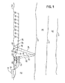
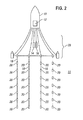
- Figs. 1-2 are views of an illustrative marine geophysical survey system.
- Fig. 3 is a functional block diagram of an illustrative marine geophysical survey system.
- Fig. 4 shows an illustrative set of recorded signals.
- Fig. 5 shows an illustrative midpoint pattern provided by a given source-receiver geometry.
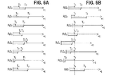
- Figs. 6A-6B show illustrative firing sequences, before and after alignment.
- Fig. 7 is a flowchart for an illustrative imaging method.
- Fig. 8 is a flowchart illustrating a source wave-field separation method.
- signals are obtained from a geophysical survey acquired with multiple geophysical energy sources actuated in a plurality of firing sequences, each sequence having a known, different time delay between a signal recording start time and a firing time of each source.
- the survey signals are organized into gathers of signals from multiple firing sequences. Each gather is then processed to form initial estimates of the wave fields for each source, which are then used to provide quieted signals from which refined estimates of the source wave fields can be obtained.
- a subsurface image can then be derived based on the refined estimates of the component signals.
- Fig. 1 shows an illustrative geophysical survey system that, in this case, collects marine seismic survey data using multiple seismic sources with a variable firing sequence.
- a seismic survey vessel 10 moves along the surface 11A of a body of water 11 such as a lake or the ocean.
- the vessel 10 typically includes equipment shown generally at 12 and referred to for convenience as a "recording system".
- the recording system 12 may include devices for selectively actuating seismic energy sources 14, 16, for actuating and recording the signals generated by the sensors or receivers 20 in response to seismic energy imparted into the water 11 and thereby into rock formations 19, 21 below the water bottom 13, and for determining geodetic position of the vessel 10, the seismic energy sources 14, 16 and each of a plurality of seismic sensors or receivers 20 at any time.
- the vessel 10 is shown towing two seismic energy sources 14, 16.
- the seismic energy sources 14, 16 can be any type of marine energy source including but not limited to air guns and water guns, or arrays of such energy sources.
- the sources 14, 16 are towed at substantially the same distance behind the vessel 10 and at different depths in the water 11.
- the sources 14, 16 may be towed by a different vessel, or may be in a fixed position.
- the vessel 10 is also shown towing an array of seismic streamers 18 (see also Fig. 2 ).
- the towed-streamer configuration is shown for illustrative purposes.
- Other suitable sensor array configurations can also be employed including, e.g., ocean bottom cable and borehole-deployed sensors.
- Any suitable sensors for seismic or other geophysical energy signals can be employed, including but not limited to pressure sensors, pressure time gradient sensors, velocity sensors, accelerometers, and any combination thereof.
- the illustrative geophysical survey system actuates a first one of the seismic energy sources, e.g., source 14.
- Energy from the first source 14 travels outwardly therefrom as shown at 24. Some of the energy travels downwardly where it is reflected at acoustic impedance boundaries, e.g., the water bottom 13 and at the boundaries 15, 17 between different rock formations 19, 21. Only the water bottom reflections are shown in Fig. 1 for clarity of the illustration. Some of the energy from the first source 14 travels upwardly where it is reflected from the water surface 11A before traveling downwardly and interacting with the formation boundaries as previously described.
- the recording system 12 also actuates a second one of the seismic energy sources, e.g., source 16, at selected delay times relative to the start of the seismic data recording, or, alternatively, at selected delay times before or after the actuation of the first source 14.
- Energy from the second source 16 travels outwardly along similar paths as does the energy from the first source 14, as shown at 22 in Fig. 1 .
- Each actuation of both the first and second seismic energy sources with the above described time delays is referred to herein as a "firing sequence".
- the time delays vary from firing sequence to firing sequence in a known random, semi-random, or systematic manner. Typically, the time delays are less than one second, but may also be longer. It is also desirable for the time delays for the firing of the sources to be different in each firing sequence.
- the difference in time delay between firing the first source and the second source should also vary in a known manner which may be random, semi-random or systematic.
- Fig. 2 shows the illustrative geophysical survey system of Fig. 1 in plan view to illustrate the towing of a plurality of laterally spaced apart streamers 18.
- the streamers 18 can be maintained in their relative lateral and longitudinal positions with respect to the vessel 10 using towing equipment 23 of types well known in the art.
- the first source 14 and the second source 16 can be laterally displaced (and/or longitudinally displaced in other examples) to avoid, in the case the sources 14, 16 are air guns or arrays thereof, having dispersed air in the water 11 from first source 14 affect the seismic energy from the second source 16 and vice versa.
- Lateral and/or longitudinal displacement is contemplated as being on the order of only a few meters so that the sources 14, 16 provide a spatial energy distribution equivalent to being that which would occur if the sources 14, 16 were in the same vertical plane and at the same longitudinal distance behind the vessel, or expressed differently, at essentially the same geodetic position.
- the effects of the water surface (11A in Fig. 1 ) will be, adjusted for water depth, substantially the same as the effect thereof on the first source 14.
- FIG. 3 A function-block diagram of the illustrative geophysical survey system is shown in Fig. 3 . It includes receivers 20 coupled to a bus 32 to communicate digital signals to data recording circuitry 36 on the vessel 10. Position information and other parameter sensors 34 are also coupled to the data recording circuitry 36 to enable the data recording circuitry to store additional information useful for interpreting the recorded data. Illustratively, such additional information may include geodetic position information for the sources and receivers, as well as weather and sea conditions.
- a general purpose digital data processing system 38 is shown coupled to the data recording circuitry 36, and is further shown coupled via bus 32 to positioning devices 28 and seismic sources 14, 16.
- Processing system 38 configures the operation of recording circuitry 36, positioning devices 28, and seismic sources 14, 16.
- Recording circuitry 36 acquires the high speed data stream(s) from receivers 20 onto a nonvolatile storage medium such as a storage array of optical or magnetic disks or tapes.
- Positioning devices 28 (including programmable diverters and depth controllers) control the position of receivers 28 and sources 14, 16.
- the illustrative system further includes a user interface having a graphical display 39 and a keyboard or other mechanism for accepting user input. The user interface enables an operator to monitor and control the operation of the survey system.
- each streamer may have an independent bus 32 for coupling to the data recording circuitry 36.
- Processing system 38 may further include a network interface for communicating stored seismic survey data to a central computing facility having powerful computing resources for processing the seismic survey data, and for receiving subsurface images or other representations of the acquired data from the central computing facility.
- the illustrative geophysical system actuates the sources and signal recording as explained above for a plurality of firing sequences while the vessel 10, sources 14, 16 and streamers 18 move through the water 11.
- the signal recordings made for each firing sequence by the recording system 12 may be referred to as a "shot record” or a "shot gather”, and each such shot record will include, for each receiver 20, traces (i.e., received signals) responsive to the seismic energy produced by both the first source 14 and the second source 16.
- Fig. 4 shows illustrative signals (R0, R1, R2, ... ) representative of the signals recorded by the receivers in response to an actuation of the sources.
- the signals may be digitized signal voltages, but they normally represent some geophysical wave attribute such as pressure, velocity, acceleration, electric field strength, or magnetic field strength.
- Each signal is associated with the position where the source was fired and the position of the acquiring receiver at the time the source was fired.
- each recorded trace has at least three aspects: a source position (for each source), a receiver position, and a time-based signal waveform. From these three aspects, a great wealth of information can be derived.
- Fig. 5 shows an overhead view of the positions 500 of a set of receivers at the time a source is triggered at position 504. If the subsurface formation layers are largely horizontal, the seismic energy that reaches the receivers does so by reflecting from a point about midway between the source and receiver positions. Thus, if a ray is traced from the source to each receiver (e.g., rays 506, 508), the midpoints 502 of those rays represent the approximate position of the reflections that resulted in the recorded signal waveform. With this understanding, it becomes possible to convert the time-based signal waveforms to depth-based signal waveforms using a pre-existing or a derived velocity model.
- Each firing of a source results in a pattern of midpoints 502 associated with the received signals.
- the midpoint pattern for each firing is a half-scale replica of the receiver position pattern.
- the sources are fired repeatedly and the receivers acquire signals associated with new sets of midpoints that largely overlap previous sets of midpoints. All of the depth-based waveforms associated with a given midpoint can be added or "stacked" to increase their signal-to-noise ratio and provide a more accurate picture of the subsurface structure at that point.
- Systems and methods that employ this processing approach typically group the received signals according to their midpoints, thereby forming "common midpoint gathers" or "CMP gathers".
- CMP gathers common midpoint gathers
- Other processing approaches are known and employed for converting received signals to subsurface images.
- Such other approaches may employ other signal groupings such as, e.g., shot gathers, common receiver position gathers a.k.a. "common station” gathers, and common offset gathers a.k.a. common channel gathers. Except for shot gathers, these various types of gathers group together signal from different firing sequences.
- Fig. 6A shows an illustrative set of timelines for signals that might be associated with a common channel gather having signals from different firing sequences.
- the timelines are labeled RiSj, where i is a given receiver number and j is a given firing sequence number.
- the timelines each begin at the recording start time and show a firing time T1 for a first source and a firing time T2 for a second source.
- the delay between the firing times varies so that when the signals are processed to align the firing times of a given source (as indicated in Fig. 6B ), the actuation times of the other source remain uncorrelated. This timing of the firing sequences makes it possible to separate the wave fields of each source when processing the signals as outlined below.
- Fig. 7 is a flowchart of an illustrative subsurface imaging method which can be implemented by general purpose processing system 308 or by a separate processing facility that receives the geophysical survey data from system 308. It begins in block 702 with the obtaining of geophysical survey data using multiple sources actuated with variable firing sequences as described above. In block 704, the system pre-processes the data to, e.g., suppress certain types of interference and to regularize the source and receiver positions associated with the signals. Such regularization can be accomplished by, e.g., interpolation to fill in for missing sensors and compensate for any misalignments. The output of this block is herein referred to as the "initial" receive signals.
- the system processes the initial receive signals to separate out the contributions of each source.
- These contributions are referred to herein as the wave fields for a given source, i.e., the wave field for the first source (aka the first source wave field) and the wave field for the second source (aka the second source wave field).
- the sources are deployed at different depths in the water to enable de-ghosting of the wave fields in a later stage.
- the initial receive signals include the wave fields from each source and a residual component.
- the system forms an initial estimate of the source wave fields, then refines each estimate based on a combination of the previous estimate with the current residual component. This block will be described in more detail with reference to Fig. 8 below.
- block 708 the separated components are re-summed with appropriate firing time delays and compared with the initial receive signals.
- a close match indicates that the bulk of the receive signal energy has been associated with the source wave fields, whereas a mismatch indicates that a significant portion of the receive signal energy is not accounted for.
- block 706 is repeated with different settings until an adequate separation of the receive signal components is achieved.
- the separated wave fields for those systems having sources at different depths are combined in a manner that eliminates the source ghost (i.e., that portion of the signal attributable to the source energy reflecting from the water's surface).
- One suitable technique is described in M. Egan et al., "Full deghosting of OBC data with over/under source acquisition", 2007 Annual Meeting, San Antonio, Tex., Society of Exploration Geophysicists , but others exist and may be used.
- the system further processes the de-ghosted wave fields to form images of the subsurface structure.
- the system migrates the de-ghosted source downwards (e.g., with wave equation propagation) from the receiver positions to obtain reflected energy wave fields as a function of position and time.
- the reflected energy wave fields may then be combined with associated transmitted energy wave fields using a correlation function or some other imaging criterion that yields a volumetric map of the subsurface reflectivity.
- the reflectivity maps from different shots can then be stacked to yield an image of the subsurface structure.
- the system then makes a visual representation of the subsurface image accessible to a user, usually with tools that enable the user to interact with the visual representation so as to explore and analyze the subsurface image in detail.
- Fig. 8 is a flowchart of an illustrative source wave field separation method that may be implemented by the system in block 706.
- the system arranges the initial receive signals into a multi-shot gather domain, i.e., grouping the signals into gathers having signals acquired in response to different firing sequences.
- Suitable gather domains are those that enable the energy from a given source to be coherent when the firing times of that source are aligned while the energy from the other source(s) is rendered incoherent.
- Suitable gather domains include, without limitation, common midpoint gathers, common station gathers, and common channel gathers.
- the system then iterates through the gathers, carrying out the following operations for each gather.
- the system processes the signals in a manner that aligns the firing times of a first source, e.g., by time-shifting the received signals. Aligning the signals to the firing times of the first source in this manner causes the energy associated with that source to be coherent while the energy for the other sources is rendered incoherent.
- the system applies a coherent/incoherent energy separation operation in block 806. Suitable techniques for doing this are known and they include, e.g., the methods disclosed by R.D. Martinez, "Weighted Slant Stack For Attenuating Seismic Noise", U.S. Pat. 6,574,567 ; P.
- the coherent energy signals obtained in block 806 serve as an initial estimate of the first source wave field, this estimate being temporarily stored in block 814 for later use.
- the system takes the incoherent energy signals and re-aligns them to synchronize the firing times of the second source.
- the system again applies the coherent/incoherent energy separation operation.
- the coherent energy signals obtained here serve as an initial estimate of the second source wave field, this estimate being stored in block 816 for later use.
- the system takes the incoherent energy signals from block 810 and re-aligns them to synchronize the firing times of the first source.
- incoherent energy signals are added to the initial estimate of the first source wave field from block 814 to form what is herein termed "quieted" signals for the first source, i.e., a representation of the initial receive signals minus the estimated contribution from the second source.
- Block 820 represents a group of operations 822-834 that may be performed repeatedly on the quieted signals for the first source with reference to the estimate for the second source wave field.
- the system applies the coherent/incoherent energy separation operation to the quieted signals for the first source.
- the resulting coherent energy signals form a refined estimate of the first source wave field, and they are stored for future use in block 830.
- the incoherent energy signals from block 822 are re-aligned to synchronize the firing times of the second source and added to the current estimate of the second source wave field to form quieted signals for the second source, in this case a representation of the initial receive signals minus the current estimate of the contribution from the first source.
- the system applies the coherent/incoherent energy separation operation again in block 826.
- the coherent energy signals form a refined estimate of the second source wave field and they are stored in block 832 for future use.
- the system re-aligns the incoherent energy signals from block 826 to synchronize the firing times of the first source.
- the re-aligned incoherent energy signals are added to the current estimate of the first source wave field from block 830 to form an improved version of the quieted signals for the first source.
- the system tests the incoherent energy signals to determine whether the operations of block 820 should be repeated. The repetition may be deemed desirable if, e.g., the energy of the incoherent signals is falling relative to previous incoherent energy signals. Alternatively, if the energy of the incoherent energy signals is above a predetermined threshold, the repetition may be deemed desirable.
- the peak amplitudes of the incoherent energy signals may be used to make these determinations.
- a fixed or minimum number of repetitions may be deemed desirable.
- the coherent/incoherent energy separation operations in Fig. 8 may be applied with different parameters to alter the proportion of energy that is found to be coherent to a given source.
- the repetition criterion in block 834 may also be altered to attempt a better convergence of the solution.
- contemplated alternative embodiments of the foregoing method will, after having determined and refined the estimated source wave fields, repeat the estimation process (blocks 804-834) with the sources being taken in a different order. The results of the two estimations may then be averaged to obtain unbiased estimates of the source wave fields.
- the foregoing embodiments of a method for determining which components of a seismic signal are a result of a particular one of a plurality of geophysical sources can take the form of a computer program stored in a computer readable medium.
- the medium may be a volatile medium (such as an SRAM or DRAM computer memory) or a nonvolatile medium (such a magnetic disk, optical disk, or a flash memory chip).
- the program includes logic operable to cause a programmable computer to perform the operations explained above with respect to Fig. 7 .
- the operations may be performed sequentially as explained above, but they may alternatively be performed in a pipelined or parallel fashion, and need not be performed strictly in the order described above.
- the method can be performed by a single processor, but it is contemplated that in most cases it would be performed by multiple processors in a localized or alternatively in a distributed computing fashion.
- the processor(s) employ one or more output devices (such as a printer or display screen) to make results perceptible to users so that they may monitor the process and evaluate the final product.
Landscapes
- Life Sciences & Earth Sciences (AREA)
- Physics & Mathematics (AREA)
- Oceanography (AREA)
- Engineering & Computer Science (AREA)
- Acoustics & Sound (AREA)
- Environmental & Geological Engineering (AREA)
- Geology (AREA)
- Remote Sensing (AREA)
- General Life Sciences & Earth Sciences (AREA)
- General Physics & Mathematics (AREA)
- Geophysics (AREA)
- Geophysics And Detection Of Objects (AREA)
Applications Claiming Priority (1)
| Application Number | Priority Date | Filing Date | Title |
|---|---|---|---|
| US13/269,991 US8982663B2 (en) | 2011-10-10 | 2011-10-10 | Subsurface imaging systems and methods with multi-source survey component segregation and redetermination |
Publications (3)
| Publication Number | Publication Date |
|---|---|
| EP2581765A2 true EP2581765A2 (de) | 2013-04-17 |
| EP2581765A3 EP2581765A3 (de) | 2014-10-15 |
| EP2581765B1 EP2581765B1 (de) | 2022-12-07 |
Family
ID=47435692
Family Applications (1)
| Application Number | Title | Priority Date | Filing Date |
|---|---|---|---|
| EP12187860.7A Active EP2581765B1 (de) | 2011-10-10 | 2012-10-09 | Untergrund-Abbildungssystem und Methode mit Mehrquellen-Komponenten Trennung und Neuermittlung |
Country Status (6)
| Country | Link |
|---|---|
| US (1) | US8982663B2 (de) |
| EP (1) | EP2581765B1 (de) |
| AU (1) | AU2012227152B2 (de) |
| BR (1) | BR102012025928B1 (de) |
| MX (1) | MX2012011787A (de) |
| SG (1) | SG189615A1 (de) |
Cited By (1)
| Publication number | Priority date | Publication date | Assignee | Title |
|---|---|---|---|---|
| NO346585B1 (en) * | 2014-04-14 | 2022-10-17 | Pgs Geophysical As | Near-continuous time-based marine seismic data acquisition and processing |
Families Citing this family (16)
| Publication number | Priority date | Publication date | Assignee | Title |
|---|---|---|---|---|
| AU2013208683A1 (en) | 2012-01-12 | 2014-07-31 | Geco Technology B.V. | Simultaneous marine vibrators |
| BR112014017319A8 (pt) * | 2012-01-13 | 2017-07-04 | Geco Technology Bv | método para conduzir um levantamento sísmico marinho usando uma técnica de fonte simultânea tendo sequências de disparo nss, sistema de levantamento sísmico marinho, sistema de processamento para processar |
| US9188693B2 (en) * | 2012-03-26 | 2015-11-17 | Apache Corporation | Method for acquiring marine seismic data |
| US9442210B2 (en) | 2012-11-30 | 2016-09-13 | Pgs Geophysical As | Open collar for multi-cable towing system |
| US10338250B2 (en) | 2013-03-14 | 2019-07-02 | Pgs Geophysical As | Method of removing incoherent noise |
| US11391857B2 (en) | 2013-12-30 | 2022-07-19 | Pgs Geophysical As | Methods and systems for attenuating residual acoustic energy in seismic data |
| US10598807B2 (en) | 2014-02-18 | 2020-03-24 | Pgs Geophysical As | Correction of sea surface state |
| US10670757B2 (en) | 2014-02-26 | 2020-06-02 | Pgs Geophysical As | Methods and systems for quantifying coherency and constraining coherency-based separation in simultaneous shooting acquisition |
| US9851463B2 (en) | 2014-07-01 | 2017-12-26 | Pgs Geophysical As | Interference attenuation of a residual portion of seismic data |
| US10132946B2 (en) | 2014-08-13 | 2018-11-20 | Pgs Geophysical As | Methods and systems that combine wavefields associated with generalized source activation times and near-continuously recorded seismic data |
| US10317553B2 (en) | 2014-08-13 | 2019-06-11 | Pgs Geophysical As | Methods and systems of wavefield separation applied to near-continuously recorded wavefields |
| US9348051B2 (en) | 2014-09-16 | 2016-05-24 | Cgg Services Sa | Device and method for deblending simultaneous shooting data using annihilation filter |
| US10073183B2 (en) | 2014-10-20 | 2018-09-11 | Pgs Geophysical As | Methods and systems that attenuate noise in seismic data |
| CN105676270B (zh) * | 2015-12-31 | 2019-03-15 | 中国石油天然气集团公司 | 脉冲激发系统的控制方法和装置 |
| US10267936B2 (en) | 2016-04-19 | 2019-04-23 | Pgs Geophysical As | Estimating an earth response |
| CN116359996B (zh) * | 2023-03-30 | 2025-07-18 | 中国科学院声学研究所东海研究站 | 一种基于海底跟踪技术的浅地层剖面仪自容式工作方法 |
Citations (1)
| Publication number | Priority date | Publication date | Assignee | Title |
|---|---|---|---|---|
| US6574567B2 (en) | 2001-01-23 | 2003-06-03 | Pgs Americas, Inc. | Weighted slant stack for attenuating seismic noise |
Family Cites Families (8)
| Publication number | Priority date | Publication date | Assignee | Title |
|---|---|---|---|---|
| US5924049A (en) * | 1995-04-18 | 1999-07-13 | Western Atlas International, Inc. | Methods for acquiring and processing seismic data |
| US6882938B2 (en) * | 2003-07-30 | 2005-04-19 | Pgs Americas, Inc. | Method for separating seismic signals from two or more distinct sources |
| US20050128874A1 (en) | 2003-12-15 | 2005-06-16 | Chevron U.S.A. Inc. | Methods for acquiring and processing seismic data from quasi-simultaneously activated translating energy sources |
| US8345510B2 (en) | 2008-06-02 | 2013-01-01 | Pgs Geophysical As | Method for aquiring and processing marine seismic data to extract and constructively use the up-going and down-going wave-fields emitted by the source(s) |
| US7916576B2 (en) * | 2008-07-16 | 2011-03-29 | Westerngeco L.L.C. | Optimizing a seismic survey for source separation |
| US8395966B2 (en) * | 2009-04-24 | 2013-03-12 | Westerngeco L.L.C. | Separating seismic signals produced by interfering seismic sources |
| US8588025B2 (en) * | 2009-12-30 | 2013-11-19 | Westerngeco L.L.C. | Method and apparatus for acquiring wide-azimuth marine data using simultaneous shooting |
| US8339896B2 (en) * | 2010-08-16 | 2012-12-25 | Pgs Geophysical As | Method for separating seismic sources in marine seismic surveys |
-
2011
- 2011-10-10 US US13/269,991 patent/US8982663B2/en active Active
-
2012
- 2012-09-14 SG SG2012069126A patent/SG189615A1/en unknown
- 2012-09-17 AU AU2012227152A patent/AU2012227152B2/en active Active
- 2012-10-09 EP EP12187860.7A patent/EP2581765B1/de active Active
- 2012-10-10 MX MX2012011787A patent/MX2012011787A/es active IP Right Grant
- 2012-10-10 BR BR102012025928-1A patent/BR102012025928B1/pt active IP Right Grant
Patent Citations (1)
| Publication number | Priority date | Publication date | Assignee | Title |
|---|---|---|---|---|
| US6574567B2 (en) | 2001-01-23 | 2003-06-03 | Pgs Americas, Inc. | Weighted slant stack for attenuating seismic noise |
Non-Patent Citations (3)
Cited By (1)
| Publication number | Priority date | Publication date | Assignee | Title |
|---|---|---|---|---|
| NO346585B1 (en) * | 2014-04-14 | 2022-10-17 | Pgs Geophysical As | Near-continuous time-based marine seismic data acquisition and processing |
Also Published As
| Publication number | Publication date |
|---|---|
| SG189615A1 (en) | 2013-05-31 |
| US8982663B2 (en) | 2015-03-17 |
| EP2581765B1 (de) | 2022-12-07 |
| AU2012227152A1 (en) | 2013-05-02 |
| BR102012025928B1 (pt) | 2021-04-27 |
| US20130088938A1 (en) | 2013-04-11 |
| BR102012025928A2 (pt) | 2013-10-22 |
| AU2012227152B2 (en) | 2016-05-12 |
| MX2012011787A (es) | 2013-04-16 |
| EP2581765A3 (de) | 2014-10-15 |
Similar Documents
| Publication | Publication Date | Title |
|---|---|---|
| US8982663B2 (en) | Subsurface imaging systems and methods with multi-source survey component segregation and redetermination | |
| EP2930541B1 (de) | Trennung von seismischen signalen aus interferierenden seismischen quellen | |
| US9945972B2 (en) | Method and system for separating seismic sources in marine simultaneous shooting acquisition | |
| CA2964893C (en) | Structure tensor constrained tomographic velocity analysis | |
| US9541659B2 (en) | Noise removal from 3D seismic representation | |
| US20160139283A1 (en) | Seismic wavefield deghosting and noise attenuation | |
| WO2013080128A1 (en) | Separation of simultaneous source data | |
| AU2013230059B2 (en) | Methods and computing systems for processing data | |
| EP3062128B1 (de) | Verfahren und vorrichtung zur entmischung seismischer daten mithilfe eines nicht-gemischten datensatzes | |
| WO2017024112A1 (en) | Seismic wavefield deghosting | |
| EP3094990A1 (de) | Verarbeitung seismischer daten einschliesslich oberflächenmehrfachmodellierung für meeresgrundkabelsysteme | |
| AU2022241469A1 (en) | Seismic data recording and processing with different uncontaminated recording time lengths |
Legal Events
| Date | Code | Title | Description |
|---|---|---|---|
| PUAI | Public reference made under article 153(3) epc to a published international application that has entered the european phase |
Free format text: ORIGINAL CODE: 0009012 |
|
| AK | Designated contracting states |
Kind code of ref document: A2 Designated state(s): AL AT BE BG CH CY CZ DE DK EE ES FI FR GB GR HR HU IE IS IT LI LT LU LV MC MK MT NL NO PL PT RO RS SE SI SK SM TR |
|
| AX | Request for extension of the european patent |
Extension state: BA ME |
|
| RAP1 | Party data changed (applicant data changed or rights of an application transferred) |
Owner name: PGS GEOPHYSICAL AS |
|
| PUAL | Search report despatched |
Free format text: ORIGINAL CODE: 0009013 |
|
| AK | Designated contracting states |
Kind code of ref document: A3 Designated state(s): AL AT BE BG CH CY CZ DE DK EE ES FI FR GB GR HR HU IE IS IT LI LT LU LV MC MK MT NL NO PL PT RO RS SE SI SK SM TR |
|
| AX | Request for extension of the european patent |
Extension state: BA ME |
|
| RIC1 | Information provided on ipc code assigned before grant |
Ipc: G01V 1/38 20060101AFI20140905BHEP |
|
| 17P | Request for examination filed |
Effective date: 20150409 |
|
| RBV | Designated contracting states (corrected) |
Designated state(s): AL AT BE BG CH CY CZ DE DK EE ES FI FR GB GR HR HU IE IS IT LI LT LU LV MC MK MT NL NO PL PT RO RS SE SI SK SM TR |
|
| STAA | Information on the status of an ep patent application or granted ep patent |
Free format text: STATUS: EXAMINATION IS IN PROGRESS |
|
| 17Q | First examination report despatched |
Effective date: 20180822 |
|
| GRAP | Despatch of communication of intention to grant a patent |
Free format text: ORIGINAL CODE: EPIDOSNIGR1 |
|
| STAA | Information on the status of an ep patent application or granted ep patent |
Free format text: STATUS: GRANT OF PATENT IS INTENDED |
|
| INTG | Intention to grant announced |
Effective date: 20220610 |
|
| GRAS | Grant fee paid |
Free format text: ORIGINAL CODE: EPIDOSNIGR3 |
|
| GRAA | (expected) grant |
Free format text: ORIGINAL CODE: 0009210 |
|
| STAA | Information on the status of an ep patent application or granted ep patent |
Free format text: STATUS: THE PATENT HAS BEEN GRANTED |
|
| AK | Designated contracting states |
Kind code of ref document: B1 Designated state(s): AL AT BE BG CH CY CZ DE DK EE ES FI FR GB GR HR HU IE IS IT LI LT LU LV MC MK MT NL NO PL PT RO RS SE SI SK SM TR |
|
| REG | Reference to a national code |
Ref country code: GB Ref legal event code: FG4D |
|
| REG | Reference to a national code |
Ref country code: CH Ref legal event code: EP Ref country code: AT Ref legal event code: REF Ref document number: 1536619 Country of ref document: AT Kind code of ref document: T Effective date: 20221215 |
|
| REG | Reference to a national code |
Ref country code: DE Ref legal event code: R096 Ref document number: 602012079081 Country of ref document: DE |
|
| REG | Reference to a national code |
Ref country code: IE Ref legal event code: FG4D |
|
| REG | Reference to a national code |
Ref country code: NO Ref legal event code: T2 Effective date: 20221207 |
|
| REG | Reference to a national code |
Ref country code: LT Ref legal event code: MG9D |
|
| REG | Reference to a national code |
Ref country code: NL Ref legal event code: MP Effective date: 20221207 |
|
| PG25 | Lapsed in a contracting state [announced via postgrant information from national office to epo] |
Ref country code: SE Free format text: LAPSE BECAUSE OF FAILURE TO SUBMIT A TRANSLATION OF THE DESCRIPTION OR TO PAY THE FEE WITHIN THE PRESCRIBED TIME-LIMIT Effective date: 20221207 Ref country code: LT Free format text: LAPSE BECAUSE OF FAILURE TO SUBMIT A TRANSLATION OF THE DESCRIPTION OR TO PAY THE FEE WITHIN THE PRESCRIBED TIME-LIMIT Effective date: 20221207 Ref country code: FI Free format text: LAPSE BECAUSE OF FAILURE TO SUBMIT A TRANSLATION OF THE DESCRIPTION OR TO PAY THE FEE WITHIN THE PRESCRIBED TIME-LIMIT Effective date: 20221207 Ref country code: ES Free format text: LAPSE BECAUSE OF FAILURE TO SUBMIT A TRANSLATION OF THE DESCRIPTION OR TO PAY THE FEE WITHIN THE PRESCRIBED TIME-LIMIT Effective date: 20221207 |
|
| REG | Reference to a national code |
Ref country code: AT Ref legal event code: MK05 Ref document number: 1536619 Country of ref document: AT Kind code of ref document: T Effective date: 20221207 |
|
| PG25 | Lapsed in a contracting state [announced via postgrant information from national office to epo] |
Ref country code: RS Free format text: LAPSE BECAUSE OF FAILURE TO SUBMIT A TRANSLATION OF THE DESCRIPTION OR TO PAY THE FEE WITHIN THE PRESCRIBED TIME-LIMIT Effective date: 20221207 Ref country code: PL Free format text: LAPSE BECAUSE OF FAILURE TO SUBMIT A TRANSLATION OF THE DESCRIPTION OR TO PAY THE FEE WITHIN THE PRESCRIBED TIME-LIMIT Effective date: 20221207 Ref country code: LV Free format text: LAPSE BECAUSE OF FAILURE TO SUBMIT A TRANSLATION OF THE DESCRIPTION OR TO PAY THE FEE WITHIN THE PRESCRIBED TIME-LIMIT Effective date: 20221207 Ref country code: HR Free format text: LAPSE BECAUSE OF FAILURE TO SUBMIT A TRANSLATION OF THE DESCRIPTION OR TO PAY THE FEE WITHIN THE PRESCRIBED TIME-LIMIT Effective date: 20221207 Ref country code: GR Free format text: LAPSE BECAUSE OF FAILURE TO SUBMIT A TRANSLATION OF THE DESCRIPTION OR TO PAY THE FEE WITHIN THE PRESCRIBED TIME-LIMIT Effective date: 20230308 |
|
| P01 | Opt-out of the competence of the unified patent court (upc) registered |
Effective date: 20230516 |
|
| PG25 | Lapsed in a contracting state [announced via postgrant information from national office to epo] |
Ref country code: NL Free format text: LAPSE BECAUSE OF FAILURE TO SUBMIT A TRANSLATION OF THE DESCRIPTION OR TO PAY THE FEE WITHIN THE PRESCRIBED TIME-LIMIT Effective date: 20221207 |
|
| PG25 | Lapsed in a contracting state [announced via postgrant information from national office to epo] |
Ref country code: SM Free format text: LAPSE BECAUSE OF FAILURE TO SUBMIT A TRANSLATION OF THE DESCRIPTION OR TO PAY THE FEE WITHIN THE PRESCRIBED TIME-LIMIT Effective date: 20221207 Ref country code: RO Free format text: LAPSE BECAUSE OF FAILURE TO SUBMIT A TRANSLATION OF THE DESCRIPTION OR TO PAY THE FEE WITHIN THE PRESCRIBED TIME-LIMIT Effective date: 20221207 Ref country code: PT Free format text: LAPSE BECAUSE OF FAILURE TO SUBMIT A TRANSLATION OF THE DESCRIPTION OR TO PAY THE FEE WITHIN THE PRESCRIBED TIME-LIMIT Effective date: 20230410 Ref country code: EE Free format text: LAPSE BECAUSE OF FAILURE TO SUBMIT A TRANSLATION OF THE DESCRIPTION OR TO PAY THE FEE WITHIN THE PRESCRIBED TIME-LIMIT Effective date: 20221207 Ref country code: CZ Free format text: LAPSE BECAUSE OF FAILURE TO SUBMIT A TRANSLATION OF THE DESCRIPTION OR TO PAY THE FEE WITHIN THE PRESCRIBED TIME-LIMIT Effective date: 20221207 Ref country code: AT Free format text: LAPSE BECAUSE OF FAILURE TO SUBMIT A TRANSLATION OF THE DESCRIPTION OR TO PAY THE FEE WITHIN THE PRESCRIBED TIME-LIMIT Effective date: 20221207 |
|
| PG25 | Lapsed in a contracting state [announced via postgrant information from national office to epo] |
Ref country code: SK Free format text: LAPSE BECAUSE OF FAILURE TO SUBMIT A TRANSLATION OF THE DESCRIPTION OR TO PAY THE FEE WITHIN THE PRESCRIBED TIME-LIMIT Effective date: 20221207 Ref country code: IS Free format text: LAPSE BECAUSE OF FAILURE TO SUBMIT A TRANSLATION OF THE DESCRIPTION OR TO PAY THE FEE WITHIN THE PRESCRIBED TIME-LIMIT Effective date: 20230407 Ref country code: AL Free format text: LAPSE BECAUSE OF FAILURE TO SUBMIT A TRANSLATION OF THE DESCRIPTION OR TO PAY THE FEE WITHIN THE PRESCRIBED TIME-LIMIT Effective date: 20221207 |
|
| REG | Reference to a national code |
Ref country code: DE Ref legal event code: R097 Ref document number: 602012079081 Country of ref document: DE |
|
| PLBE | No opposition filed within time limit |
Free format text: ORIGINAL CODE: 0009261 |
|
| STAA | Information on the status of an ep patent application or granted ep patent |
Free format text: STATUS: NO OPPOSITION FILED WITHIN TIME LIMIT |
|
| PG25 | Lapsed in a contracting state [announced via postgrant information from national office to epo] |
Ref country code: DK Free format text: LAPSE BECAUSE OF FAILURE TO SUBMIT A TRANSLATION OF THE DESCRIPTION OR TO PAY THE FEE WITHIN THE PRESCRIBED TIME-LIMIT Effective date: 20221207 |
|
| 26N | No opposition filed |
Effective date: 20230908 |
|
| PG25 | Lapsed in a contracting state [announced via postgrant information from national office to epo] |
Ref country code: SI Free format text: LAPSE BECAUSE OF FAILURE TO SUBMIT A TRANSLATION OF THE DESCRIPTION OR TO PAY THE FEE WITHIN THE PRESCRIBED TIME-LIMIT Effective date: 20221207 |
|
| REG | Reference to a national code |
Ref country code: DE Ref legal event code: R119 Ref document number: 602012079081 Country of ref document: DE |
|
| PG25 | Lapsed in a contracting state [announced via postgrant information from national office to epo] |
Ref country code: IT Free format text: LAPSE BECAUSE OF FAILURE TO SUBMIT A TRANSLATION OF THE DESCRIPTION OR TO PAY THE FEE WITHIN THE PRESCRIBED TIME-LIMIT Effective date: 20221207 Ref country code: MC Free format text: LAPSE BECAUSE OF FAILURE TO SUBMIT A TRANSLATION OF THE DESCRIPTION OR TO PAY THE FEE WITHIN THE PRESCRIBED TIME-LIMIT Effective date: 20221207 |
|
| REG | Reference to a national code |
Ref country code: CH Ref legal event code: PL |
|
| REG | Reference to a national code |
Ref country code: BE Ref legal event code: MM Effective date: 20231031 |
|
| PG25 | Lapsed in a contracting state [announced via postgrant information from national office to epo] |
Ref country code: LU Free format text: LAPSE BECAUSE OF NON-PAYMENT OF DUE FEES Effective date: 20231009 |
|
| PG25 | Lapsed in a contracting state [announced via postgrant information from national office to epo] |
Ref country code: LU Free format text: LAPSE BECAUSE OF NON-PAYMENT OF DUE FEES Effective date: 20231009 |
|
| PG25 | Lapsed in a contracting state [announced via postgrant information from national office to epo] |
Ref country code: CH Free format text: LAPSE BECAUSE OF NON-PAYMENT OF DUE FEES Effective date: 20231031 |
|
| PG25 | Lapsed in a contracting state [announced via postgrant information from national office to epo] |
Ref country code: FR Free format text: LAPSE BECAUSE OF NON-PAYMENT OF DUE FEES Effective date: 20231031 Ref country code: DE Free format text: LAPSE BECAUSE OF NON-PAYMENT OF DUE FEES Effective date: 20240501 Ref country code: CH Free format text: LAPSE BECAUSE OF NON-PAYMENT OF DUE FEES Effective date: 20231031 |
|
| PG25 | Lapsed in a contracting state [announced via postgrant information from national office to epo] |
Ref country code: BE Free format text: LAPSE BECAUSE OF NON-PAYMENT OF DUE FEES Effective date: 20231031 |
|
| PG25 | Lapsed in a contracting state [announced via postgrant information from national office to epo] |
Ref country code: IE Free format text: LAPSE BECAUSE OF NON-PAYMENT OF DUE FEES Effective date: 20231009 |
|
| PG25 | Lapsed in a contracting state [announced via postgrant information from national office to epo] |
Ref country code: IE Free format text: LAPSE BECAUSE OF NON-PAYMENT OF DUE FEES Effective date: 20231009 |
|
| PG25 | Lapsed in a contracting state [announced via postgrant information from national office to epo] |
Ref country code: BG Free format text: LAPSE BECAUSE OF FAILURE TO SUBMIT A TRANSLATION OF THE DESCRIPTION OR TO PAY THE FEE WITHIN THE PRESCRIBED TIME-LIMIT Effective date: 20221207 |
|
| PG25 | Lapsed in a contracting state [announced via postgrant information from national office to epo] |
Ref country code: BG Free format text: LAPSE BECAUSE OF FAILURE TO SUBMIT A TRANSLATION OF THE DESCRIPTION OR TO PAY THE FEE WITHIN THE PRESCRIBED TIME-LIMIT Effective date: 20221207 |
|
| PG25 | Lapsed in a contracting state [announced via postgrant information from national office to epo] |
Ref country code: CY Free format text: LAPSE BECAUSE OF FAILURE TO SUBMIT A TRANSLATION OF THE DESCRIPTION OR TO PAY THE FEE WITHIN THE PRESCRIBED TIME-LIMIT; INVALID AB INITIO Effective date: 20121009 |
|
| PG25 | Lapsed in a contracting state [announced via postgrant information from national office to epo] |
Ref country code: HU Free format text: LAPSE BECAUSE OF FAILURE TO SUBMIT A TRANSLATION OF THE DESCRIPTION OR TO PAY THE FEE WITHIN THE PRESCRIBED TIME-LIMIT; INVALID AB INITIO Effective date: 20121009 |
|
| PGFP | Annual fee paid to national office [announced via postgrant information from national office to epo] |
Ref country code: NO Payment date: 20250922 Year of fee payment: 14 |
|
| PGFP | Annual fee paid to national office [announced via postgrant information from national office to epo] |
Ref country code: GB Payment date: 20250917 Year of fee payment: 14 |
|
| PG25 | Lapsed in a contracting state [announced via postgrant information from national office to epo] |
Ref country code: TR Free format text: LAPSE BECAUSE OF FAILURE TO SUBMIT A TRANSLATION OF THE DESCRIPTION OR TO PAY THE FEE WITHIN THE PRESCRIBED TIME-LIMIT Effective date: 20221207 |