US10598807B2 - Correction of sea surface state - Google Patents
Correction of sea surface state Download PDFInfo
- Publication number
- US10598807B2 US10598807B2 US14/338,516 US201414338516A US10598807B2 US 10598807 B2 US10598807 B2 US 10598807B2 US 201414338516 A US201414338516 A US 201414338516A US 10598807 B2 US10598807 B2 US 10598807B2
- Authority
- US
- United States
- Prior art keywords
- data
- source
- sea surface
- surface state
- receivers
- Prior art date
- Legal status (The legal status is an assumption and is not a legal conclusion. Google has not performed a legal analysis and makes no representation as to the accuracy of the status listed.)
- Active, expires
Links
- 238000012937 correction Methods 0.000 title claims abstract description 57
- XLYOFNOQVPJJNP-UHFFFAOYSA-N water Substances O XLYOFNOQVPJJNP-UHFFFAOYSA-N 0.000 claims abstract description 46
- 238000000034 method Methods 0.000 claims abstract description 32
- 230000000694 effects Effects 0.000 claims description 38
- 238000012545 processing Methods 0.000 claims description 21
- 238000005259 measurement Methods 0.000 claims description 13
- 238000000354 decomposition reaction Methods 0.000 claims description 11
- 230000015572 biosynthetic process Effects 0.000 claims description 10
- 238000000926 separation method Methods 0.000 claims description 10
- 238000001914 filtration Methods 0.000 claims description 6
- 238000013461 design Methods 0.000 claims description 5
- 230000008569 process Effects 0.000 claims description 3
- 238000010586 diagram Methods 0.000 description 26
- 230000006870 function Effects 0.000 description 17
- 230000008859 change Effects 0.000 description 11
- 238000004891 communication Methods 0.000 description 8
- 230000003068 static effect Effects 0.000 description 7
- 238000005755 formation reaction Methods 0.000 description 6
- 230000008901 benefit Effects 0.000 description 5
- 238000004458 analytical method Methods 0.000 description 4
- 230000009471 action Effects 0.000 description 3
- 239000002245 particle Substances 0.000 description 3
- 230000004044 response Effects 0.000 description 3
- 238000005516 engineering process Methods 0.000 description 2
- 239000012530 fluid Substances 0.000 description 2
- 238000003384 imaging method Methods 0.000 description 2
- 229910052500 inorganic mineral Inorganic materials 0.000 description 2
- 239000011707 mineral Substances 0.000 description 2
- 239000007787 solid Substances 0.000 description 2
- 238000004364 calculation method Methods 0.000 description 1
- 230000001427 coherent effect Effects 0.000 description 1
- 238000009795 derivation Methods 0.000 description 1
- 238000011161 development Methods 0.000 description 1
- 238000010891 electric arc Methods 0.000 description 1
- 238000010892 electric spark Methods 0.000 description 1
- 239000002360 explosive Substances 0.000 description 1
- 238000010304 firing Methods 0.000 description 1
- 238000009499 grossing Methods 0.000 description 1
- 230000003993 interaction Effects 0.000 description 1
- 238000012986 modification Methods 0.000 description 1
- 230000004048 modification Effects 0.000 description 1
- 238000012544 monitoring process Methods 0.000 description 1
- 230000003287 optical effect Effects 0.000 description 1
- 230000010355 oscillation Effects 0.000 description 1
- 230000002093 peripheral effect Effects 0.000 description 1
- 239000003208 petroleum Substances 0.000 description 1
- 239000011435 rock Substances 0.000 description 1
- 238000001228 spectrum Methods 0.000 description 1
- 238000010183 spectrum analysis Methods 0.000 description 1
Images


Classifications
-
- G—PHYSICS
- G01—MEASURING; TESTING
- G01V—GEOPHYSICS; GRAVITATIONAL MEASUREMENTS; DETECTING MASSES OR OBJECTS; TAGS
- G01V1/00—Seismology; Seismic or acoustic prospecting or detecting
- G01V1/38—Seismology; Seismic or acoustic prospecting or detecting specially adapted for water-covered areas
-
- G—PHYSICS
- G01—MEASURING; TESTING
- G01V—GEOPHYSICS; GRAVITATIONAL MEASUREMENTS; DETECTING MASSES OR OBJECTS; TAGS
- G01V1/00—Seismology; Seismic or acoustic prospecting or detecting
- G01V1/28—Processing seismic data, e.g. for interpretation or for event detection
- G01V1/36—Effecting static or dynamic corrections on records, e.g. correcting spread; Correlating seismic signals; Eliminating effects of unwanted energy
- G01V1/364—Seismic filtering
- G01V1/366—Seismic filtering by correlation of seismic signals
Definitions
- a marine seismic survey vessel tows one or more seismic sources below the surface of the water and over a subterranean formation to be surveyed for mineral deposits.
- Seismic receivers may be located on or near the water bottom, on one or more streamers towed by the source vessel, or on one or more streamers towed by another vessel.
- the source vessel typically contains marine seismic survey equipment, such as navigation control, seismic source control, seismic receiver control, and recording equipment.
- the seismic source control may cause the one or more seismic sources, which are typically air guns or marine vibrators, to produce acoustic signals at selected times (often referred to as “firing a shot” or “shooting”).
- Each acoustic signal is essentially a sound wave that travels down through the water and into the subterranean formation. At each interface between different types of rock, a portion of the sound wave may be refracted, a portion of the sound wave may be transmitted, and another portion may be reflected back toward the body of water to propagate toward the surface.
- the streamers towed behind the vessel are generally elongated cable-like structures.
- Each streamer includes a number of seismic receivers that detect pressure and/or particle motion changes in the water created by the sound waves reflected back into the water from the subterranean formation. The receivers thereby measure a wavefield that was ultimately initiated by the actuation of the seismic source. In this sense, the acoustic signals (or “shots”) are actuated at the sources, and the receivers measure a wavefield based on the actuation of the sources.
- FIGS. 1A-1D illustrate coordinates and terminology associated with correction of sea surface state.
- FIG. 2 illustrates a diagram including two shots actuated at a plurality of receivers according to one or more embodiments of the present disclosure.
- FIG. 3 illustrates a diagram including two shots actuated at a plurality of receivers according to one or more embodiments of the present disclosure.
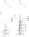
- FIG. 4 illustrates a diagram including five shots actuated at a plurality of receivers according to one or more embodiments of the present disclosure.
- FIG. 5 illustrates a diagram including five shots actuated at a plurality of receivers according to one or more embodiments of the present disclosure.
- FIG. 6 illustrates a diagram illustrating the collection of data according to one or more embodiments of the present disclosure.
- FIG. 7 illustrates a diagram including the use of sources, channels, and receivers, along with various cross-correlations according to one or more embodiments of the present disclosure.
- FIG. 8 illustrates a diagram relating to shot point direction, constant receiver direction, and constant channel direction according to one or more example embodiments of the present disclosure.
- FIG. 9 illustrates an example shot point gather according to one or more embodiments of the present disclosure.
- FIG. 10 illustrates an example shot point gather according to one or more embodiments of the present disclosure.
- FIG. 11 illustrates an example shot point gather according to one or more embodiments of the present disclosure.
- FIG. 12 illustrates an example two-dimensional (2D) receiver gather before correction of sea surface state according to one or more embodiments of the present disclosure.
- FIG. 13 illustrates an example 2D receiver gather plus linear move out (LMO) before correction of sea surface state according to one or more embodiments of the present disclosure.
- LMO linear move out
- FIG. 14 illustrates an example 2D receiver gather plus LMO after correction of sea surface state according to one or more embodiments of the present disclosure.
- FIG. 15 illustrates an example 2D receiver gather after correction of sea surface state according to one or more embodiments of the present disclosure.
- FIG. 16 illustrates a diagram of a system for correction of sea surface state according to one or more embodiments of the present disclosure.
- FIG. 17 illustrates a diagram of a machine for correction of sea surface state according to one or more embodiments of the present disclosure.
- FIG. 18 illustrates an example method for correction of sea surface state according to one or more embodiments of the present disclosure.
- FIG. 19 illustrates an example method for correction of sea surface state according to one or more embodiments of the present disclosure.
- the present disclosure is related to analyzing and correcting for the effects of sea surface state in marine seismic surveying.
- sea conditions may be uncontrollable.
- waves and other sea surface factors may interrupt and/or interfere with seismic recording.
- Embodiments of the present disclosure allow for correction or compensation of these interruptions and interferences. For instance, embodiments of the present disclosure can reduce and/or remove effects of the sea surface state variations (e.g., due to waves, swells, etc.) on up-going survey data.
- This disclosure is related generally to the field of marine seismic surveying.
- this disclosure may have applications in marine seismic surveying, in which one or more towed sources are used to generate wavefields, and receivers—either towed or ocean bottom—receive reflected seismic energy generated by the seismic sources.
- the disclosure may also have application to the analysis of the sea surface state in marine seismic surveying.
- FIGS. 1A-1D illustrate coordinates and terminology associated with correction of a sea surface state.
- FIG. 1A illustrates an elevation or xz-plane view of an example marine seismic survey vessel 109 towing a source 103 (e.g., one or more airguns or marine vibrators) and a streamer 113 located beneath a free surface 115 . In practice, source 103 and streamer 113 may be towed by the same or different vessels.
- FIG. 1A represents a snapshot, at an instant in time, of the undulating free surface 115 and corresponding smooth wave-like shape in the streamer 113 .
- FIG. 1B includes xy-plane 117 and FIG.
- 1A includes an xz-plane 119 of the same Cartesian coordinate system used to specify coordinate locations within the fluid volume with respect to three orthogonal, spatial coordinate axes labeled x, y and z.
- the x coordinate uniquely specifies the position of a point in a direction parallel to the path of travel of the vessel 109 at a particular moment in time
- the y coordinate uniquely specifies the position of a point in a direction perpendicular to the x axis and substantially parallel to the free surface 115 at vessel 109 at a particular moment in time
- the z coordinate uniquely specifies the position of a point perpendicular to the xy-plane 117 at a particular moment in time.
- Shaded disks such as shaded disks 105 - 1 and 105 - 2 , represent receivers spaced along streamer 113 .
- Receivers 105 can include, for instance, seismic receivers and/or electromagnetic receivers, among others. Although illustrated on a towed streamer 113 , receivers 105 may be located on ocean bottom cables or on nodes attached near or on the water bottom.
- FIG. 1A includes an illustration of a shot and wave paths 129 - 1 , 129 - 2 from the source 103 at a corresponding number of receivers 105 - 1 , 105 - 2 . Also illustrated at the corresponding number of receivers 105 - 1 , 105 - 2 is arrival of a corresponding number of signals 127 - 1 , 127 - 2 from the source 103 reflected off the free surface 115 .
- “source-side” can refer to some action, item, or event associated with the source (not with the receiver), affecting a source, and/or positioned near or in the same location as the source, among others. “Receiver-side” can refer to the same association of actions, items, or events with a receiver.
- FIG. 1A illustrates up-going wavefield direction 133 and down-going wavefield direction 135 , as will be further discussed herein.
- FIG. 1B illustrates a top or xy-plane view of the marine seismic survey vessel 109 towing a source 103 with source units 103 - 1 , 103 - 2 , 103 - 3 and four separate streamers 113 - 1 , 113 - 2 , 113 - 3 , 113 - 4 located beneath a free surface.
- Embodiments are not limited to three source units in a source, as a source can include more or fewer source units. Some embodiments can include 35 source units in the source.
- the source can be one-dimensional (e.g., arranged in a line as shown), two-dimensional (e.g., arranged in a rectangular grid), or three-dimensional (e.g., arranged in a cube).
- Source 103 may be a number of types including, but not limited to a small explosive charge, an electric spark or arc, a marine vibrator, and/or a seismic source gun, among others.
- Source 103 may comprise a number of source elements in a source configuration, and can, without limitation, generate a short-duration impulse.
- Embodiments are not limited to a particular number of streamers and can include more or fewer than are shown. Some embodiments can include 24 or more streamers.
- the streamers 113 - 1 , 113 - 2 , 113 - 3 , 113 - 4 can be modeled as a planar horizontal acquisition surface located beneath the free surface. However in practice, the acquisition surface can be smoothly varying due to active sea currents and weather conditions.
- the towed streamers may also undulate as a result of dynamic conditions of the fluid.
- the coordinates of a particular receiver are given by (x, y, z) taking into account both the xz-plane 119 and the xy-plane 117 .
- the receiver array may vary in the z direction (e.g., receivers disposed farther from the vessel may be deeper than those closer to the vessel).
- one or more of the streamers may be towed at a different depth than other streamers, thereby creating an acquisition volume.
- Various embodiments of the present disclosure provide methods to correct marine seismic data for sea surface state variations.
- the correction can occur, in some instances, at the source location, at the receiver location, or both.
- rough sea surfaces can cause amplitude and phase perturbations in acquired seismic data.
- Sea surface state correction in accordance with the present disclosure can compensate for at least some of these perturbations, resulting in smoothed time-varying sea surface states.
- advantage may be taken of a dual-receiver streamer (e.g., streamer receivers include both hydrophones and geophones), or any multi-sensor acquisition which allows a mathematical separation of the up-going wavefields and down-going wavefields.
- up-going wavefields can include wavefields scattered upwards from the earth or formations therein, and “down-going wavefields” can include wavefields reflected downwards from the sea surface.
- a down-going wavefield typically contains a direct wave, typically contains receiver-side surface multiples and water-column reverberations, while an up-going wavefield typically contains primaries and source-side ghosts and internal multiples. Since the primary reflections are contained only in the up-going wavefield, wavefield separation can be used to isolate the signal from the primary reflections.
- up-going data may be considered as being free from any receiver-side sea surface effect. Therefore, any roughness observable on data reflected from shot point to shot point (the points at which a source is actuated) may be a side effect of the deviations in source datum caused by the sea surface state at the source location.
- time-shifts associated with the source datum deviations may be identified and corrected for.
- the sea surface state (e.g., the wave height, time-derivative changes in wave height, wave frequency, and/or other sea conditions occurring at the sea surface) may vary from shot to shot in a marine seismic survey.
- source wavelet wave-like oscillation used for signal processing
- travel time may also vary from shot to shot.
- the effect of the sea surface state may be particularly noticeable in a receiver domain ensemble, where a single trace, which can include gathered information/data, may come from different shot points. It may manifest as a random jittery effect that could (perhaps wrongly) be qualified as “noise.”
- assumptions can be made and a workflow may be devised that provides a surface-consistent static correction.
- FIGS. 1A and 1B illustrate a single vessel, a plurality of vessels may be present, with some or all of the vessels towing streamers and some or all of the vessels towing sources and actuating shots.
- the streamers may be towed in different directions, depths, and/or angles, among other differences.
- Receivers may be located on streamers, ocean bottom cables, or on nodes located on or near the water bottom.
- FIG. 1C illustrates an example technique for acquiring seismic data that may be used in correction of sea surface state in one or more embodiments of the present disclosure.
- the example illustrated in FIG. 1C is two-dimensional, meaning that the technique is related to data acquired using a single seismic streamer 113 or an ocean bottom cable 131 .
- Examples of the present disclosure Call also be used with three-dimensional acquisition techniques, in which more than one seismic source and/or laterally spaced streamers and/or ocean bottom cables are used to acquire seismic data.
- Examples of the present disclosure can also be used with receivers located on nodes near or on the water bottom 153 .
- vessel 109 can tow a source 103 that can be actuated at selected times.
- a streamer 113 is also towed by the vessel 109 .
- the streamer 113 includes receivers 105 - 1 , . . . , 105 - 6 at spaced positions along the cable 113 .
- Each receiver can he responsive, for example, to the pressure in the water or to changes in pressure, such as, for instance, changes in pressure with respect to time. Examples of the present disclosure can also be used with receivers that are sensitive to particle motion or changes in particle motion.
- an ocean bottom cable (OBC) 151 can be deployed on the water bottom 153 .
- the OBC 151 can include, for instance, receivers 155 - 1 . 155 - 6 spaced along OBC 151 . Signals generated by the receivers 155 - 1 , . . . , 155 - 6 can be recorded by a. recording unit 157 for later retrieval and processing.
- both streamers and OBCs can be used to record signals to be processed according to the present disclosure.
- receivers located on nodes near or on the water bottom 153 may be used to record signals to be processed according to the present disclosure.
- acoustic energy travels downwardly, at 159 .
- Some of the downwardly traveling energy 159 penetrates the water bottom 153 and reaches a subsurface layer boundary 199
- Acoustic energy can be reflected from the layer boundary 199 , whereupon the reflected energy travels upwardly, as shown generally at 163 .
- Acoustic energy can also be reflected from the water bottom 153 , whereupon the reflected energy travels upwardly, as shown generally at 161 .
- the upwardly traveling acoustic energy 161 , 163 can be detected by the receivers 105 - 1 , . . . , 105 - 6 on the streamer 113 (or the receivers 155 - 1 , . . .
- the upwardly traveling energy 161 , 163 can reflect from the water surface 115 , whereupon the energy travels downwardly again, as shown at 101 .
- the water surface reflected energy 101 can be detected by the receivers 105 - 1 , . . . , 105 - 6 , (and/or 155 - 1 , . . . , 155 - 6 ) resulting in a ghost signal.
- the water surface reflected energy 101 also may be reflected from the water bottom 153 , and becomes upwardly traveling energy, shown generally at 107 . Further, acoustic energy can reflect from the water surface (down-going energy 101 ) and can again reflect from the water bottom (up-going energy 107 ) a plurality of times, resulting in water-layer multiple reflections.
- the acoustic energy detected by the receivers 105 - 1 , . . . , 105 - 6 , (and/or 155 - 1 , . . . , 155 - 6 ) referred to as a “total wavefield”, includes both upwardly traveling energy (“up-going wavefield”) and downwardly traveling energy (“down-going wavefield”),
- the up-going and down-going wavefields include components resulting from subsurface reflectors, such as boundary 199 , and from water surface and water bottom reflections.
- FIG. 1D illustrates an example nodal receiver geophysical survey system including a vessel 109 that moves along the surface of a body of water such as a lake or the sea.
- Data acquisition in accordance with one or more embodiments of the present disclosure can be performed via a nodal receiver geophysical survey system as illustrated in FIG. 1D .
- Sources 103 - 1 and 103 - 2 can be actuated, and the resultant wavefield can be detected with nodal receivers 116 positioned on the water bottom.
- a method for correction of a sea surface state can include receiving geophysical data from a seismic survey, wherein the seismic survey utilizes a plurality of receivers disposed in a body of water, and at least one source in the body of water, actuated at a plurality of shot points.
- the method can also include identifying, in the geophysical data, a wavefield based on the actuation of the at least one source, and determining, based on the identified wavefield, a sea surface state at the at least one source at one of the plurality of shot points.
- determining the sea surface state can include separating up-going portions of the measured wavefield from down-going portions of the measured wavefield, determining source-side effects in the up-going wavefield, cross-correlating constant receiver and constant channel ensembles, and statistically filtering and extracting a surface consistent time correction to apply to the plurality of shot points based on the cross-correlation.
- FIG. 2 illustrates a diagram 200 including two shots actuated at a plurality of receivers according to one or more embodiments of the present disclosure.
- FIG. 2 illustrates an example in which a source 203 is actuated at a set of receivers Rn 205 at different times t 1 and t 2 , for instance at 202 and 204 , respectively.
- the two shots are actuated from the same source 203 , but at different times t 1 and t 2 .
- Source 203 moves from shot point S 1 at time t 1 (at 202 ) to shot point S 2 at time t 2 (at 204 ). As illustrated in FIG.
- Seismic source 203 can represent an appropriate submerged seismic source, which may be activated to generate an acoustic wavefield. Source 203 may be towed by a vessel or otherwise disposed in the marine environment.
- source 203 may be approximately 7 meters from sea surface 215 at each shot point S 1 and S 2 , though embodiments are not limited to this distance or to identical depths at shot point S 1 and S 2 .
- the plurality of receivers Rn 205 simultaneously record the wavefield resulting from source 203 actuating at shot point S 1 at time t 1 .
- the distance between the receivers Rn 205 and the sea surface 215 is approximately 15 meters at the distal end of streamer 213 , though embodiments are not limited to this distance or to each of the receivers Rn 205 being at identical depths.
- the plurality of receivers Rn 205 simultaneously record the wavefield resulting from source 203 actuation at shot point S 2 at time t 2 with a distance of 15 m between the distal end of streamer 213 and the sea surface 215 , however, embodiments are not limited to this distance, to each of the receivers Rn 205 being at identical depths, or to the same depth of the distal end of streamer 213 when recording wavefields from actuations of the source 203 at times t 1 and t 2 .
- the measured wavefield may include both up-going and down-going portions. These portions can be separated, and source-side effects in the up-going portion can be determined.
- An example of wave separation, also known as decomposition, is described in United States Patent Application Publication Number 2014/0016436, which is hereby incorporated by reference.
- a sea surface state variation as it relates to the source side can be determined.
- Cross-correlations can be performed between constant receiver and constant channel ensembles.
- a surface time correction to apply to the plurality of shot points can be statistically filtered and extracted based on the source-side effects and cross-correlations. For example, this surface time correction can correct for sea surface state variations, making for more accurate, smoother sea surface state data.
- FIG. 3 illustrates a diagram 300 including two shots actuated at a plurality of receivers according to one or more embodiments of the present disclosure.
- the actuated shots can include a series of shots actuated at different times from a single source.
- the shots can be actuated at nearly the same time and/or within a particular time interval.
- FIG. 3 illustrates an example in which two shots, occurring at shot points S 1 and S 2 , are actuated from source units 303 - 1 and 303 - 2 , respectively, at a plurality of receivers Rn 305 . While only one receiver is shown in FIG.
- Rn 305 can represent a plurality of receivers, and the plurality of receivers may be disposed on one or more streamers, one or more ocean bottom cables, a plurality of nodes near or on the water bottom, or any combination thereof.
- the plurality of receivers Rn 305 because of the simultaneous recording of the plurality of receivers Rn 305 , whatever the sea condition, there may be some continuity between traces within a given shot point (e.g., shot point S 1 or S 2 ). Reciprocally, for a given receiver position, all the traces may be coming from different shot points shot at different times, which therefore may express sea surface state variation at each shooting time.
- the arrows as illustrated in FIGS. 3-5 are not meant to be directional. Rather FIGS.
- each source unit 303 - 1 , 303 - 2 may be a particular distance 312 - 1 , 312 - 2 away from a sea surface 315 .
- these distances 312 - 1 - and 312 - 2 can be the same, however, they are not required to be the same.
- FIG. 4 illustrates a diagram 400 including five shots actuated at a plurality of receivers according to one or more embodiments of the present disclosure.
- the actuated shots can include a series of shots actuated at different times from a single source.
- the shots can be actuated at nearly the same time and/or within a particular time interval.
- FIG. 4 illustrates an example in which five shots, occurring at shot points S 1 , S 2 , S 3 , S 4 and S 5 are actuated from source units 403 - 1 , 403 - 2 , 403 - 3 , 403 - 4 , and 403 - 5 , respectively at a plurality of receivers Rn 405 . While only one receiver is shown in FIG.
- Rn 405 can represent a plurality of receivers, and the plurality of receivers may be disposed on one or more streamers, one or more ocean bottom cables, a plurality of nodes near or on the water bottom, or any combination thereof
- the plurality of receivers Rn 405 may simultaneously record a wavefield based on the five shots at a particular time. Similar to FIGS. 2 and 3 , because of simultaneous recording of the plurality of receivers Rn 405 , whatever the sea condition, there may be some continuity between traces at different receivers from a given shot point. Reciprocally, for a given receiver position, traces may be coming from different shot points shot at different times, which therefore may express sea surface state variation at each shooting time.
- consecutive shot points S 1 , S 2 , S 3 , S 4 , and S 5 are shot at a regular time interval during which a vessel has moved up and down on the sea surface 415 ; the state of sea surface 415 is illustrated for each of the shot points S 1 , S 2 , S 3 , S 4 , and S 5 by sea surface 415 shown as multiple wavy lines.
- sea surface 415 shown as multiple wavy lines.
- each source unit may be approximately 7 meters from sea surface 415 , though embodiments are not limited to this distance or that each source unit is at the same depth.
- FIG. 5 illustrates a diagram 500 including five shots actuated at a plurality of receivers according to one or more embodiments of the present disclosure.
- the actuated shots can include a series of shots actuated at different times from a single source.
- the shots can be actuated at nearly the same time and/or within a particular time interval.
- Diagram 500 includes five shots occurring at shot points S 1 , S 2 , S 3 , S 4 , and S 5 actuated at a plurality of receivers Rn 505 from source units 503 - 1 , 503 - 2 , 503 - 4 , and 503 - 5 , respectively. While only one receiver is shown in FIG.
- Rn 505 can represent a plurality of receivers, and the plurality of receivers may be disposed on one or more streamers, one or more ocean bottom cables, a plurality of nodes near or on the water bottom, or any combination thereof.
- the plurality of receivers Rn 505 can be simultaneously recording wavefields resulting from shots at shot points S 1 , . . . , S 5 at a particular time. Similar to FIGS. 2-4 , because of the simultaneous recording, whatever the sea condition, there may be some continuity between traces within a given shot point. Reciprocally, for a given receiver position, traces may be coming from different shot points shot at different times, which therefore may express sea surface state variation at each shooting time. However, in contrast to FIG. 4 , FIG.
- FIG. 5 illustrates a culmination of the sea surface 515 and its state above the consecutive shot points S 1 , S 2 , S 3 , S 4 , and S 5 .
- shot points S 1 , S 2 , S 3 , S 4 , and S 5 are not aligned on a horizontal line. This may result in a vessel travel time difference from shot point to shot point as the sea surface state is always changing.
- the variations in the sea surface state at the source may cause the absolute height of a source to differ from shot to shot.
- all traces may express a continuous sea surface state.
- all the traces may come from different source positions shot at different times and sea surface state variation. The demonstrated effect may be expressed as a random time delay between traces.
- FIG. 6 illustrates a diagram 600 illustrating the collection of data according to one or more embodiments of the present disclosure.
- the embodiment illustrated in FIG. 6 can, in some examples, be applied only to up-going data, and may be applied after de-noise and wavefield separation of up-going and down-going data processes have been applied in a shot point domain.
- a channel can include data recorded from a receiver at one location on a streamer.
- a channel can also refer to, for instance, the actual recording device inserted into a streamer at a regular distance interval (e.g., 12.5 meters).
- a streamer may contain hundreds of channels.
- An example time window 638 can be designed starting above the water bottom (e.g., above first order multiple 636 , taking into account water-bottom reflection 634 ) and finishing at twice the water bottom. In the example illustrated in FIG. 6 , this bottom period may include, for instance, a maximum of 500 ms.
- the constant receiver and constant channel ensembles can be cross-correlated, gathered, and surface consistent time correction can be statistically filtered and extracted to apply to every shot point.
- constant receiver can refer to data recorded from a particular location in the water.
- a constant receiver can include data that would have been recorded from the particular location if there was a stationary receiver placed at that particular location; however, a stationary receiver may not be possible in streamer-based acquisition due to the streamer constantly moving.
- a constant receiver can be constructed by taking data recorded from one channel when it was in a first location, and combining it with data recorded from the next channel, for instance, when it had moved to the particular, desired location. This can be performed for all channels on the streamer.
- a constant receiver can be considered a fixed point in space.
- data collected can include all data that has been recorded from one location.
- a “constant channel”, as used herein, can represent that data being recorded from the same physical receiver, i.e., a fixed position on the streamer. Because the streamer is constantly moving through the water, this can represent data from a number of different locations.
- FIG. 7 illustrates a diagram 700 including the use of sources, channels, and receivers, along with various cross-correlations according to one or more embodiments of the present disclosure.
- Diagram 700 includes the use of sources at shot points S 1 to Sn, channels c 1 to cn, and receivers r 1 to m, along with various cross-correlations.
- a vessel towing a source may be thought of as moving toward the right side of FIG. 7 in shot point direction 748 , such that each horizontal line represents a shot point S 1 , S 2 , Sn (e.g., the vessel is shooting at regular increments).
- the vessel also tows a streamer on which a plurality of receivers is located.
- a constant receiver direction is illustrated at 742 and 744
- the constant channel direction (assuming a given receiver is located at constant location along the streamer) is illustrated at 750 .
- the constant channel may change from source-to-source based on how far the vessel has moved.
- each line labeled r 1 , r 2 , . . . , rn can represent a receiver position
- each vertical dash labeled c 1 , c 2 , . . . , cn can represent a channel position (e.g., first channel, second channel, etc.).
- constant receiver direction 744 and constant channel direction 750 are used as an explanation of diagram 700 .
- diagram 700 can represent recording of data from shots at a plurality of shot points S 1 , S 2 , . . . , Sn and a plurality of channels c 1 , . . .
- Diagram 700 can be used to aid in understanding a layout of an acquisition, for instance. However, diagram 700 is schematized to represent acquisition of the data, but is not a drawn picture of the acquisition. Shot point direction 748 can indicate a progression of data acquisition from shot point S 1 through shot point S 2 , through shot point S 3 , and so on through shot point Sn. Shot point direction 748 can be used to indicate the direction in which to read diagram 700 , for instance.
- Information/data regarding consecutive shot points S 1 , S 2 , . . . , Sn can be gathered at each receiver and channel position.
- Each trace can be embedded, as illustrated in FIG. 11 , and each trace can include information/data about the sea surface state at sources associated with consecutive shot points S 1 , S 2 , . . . , Sn.
- cross-correlation of the data the effect of the sea above a source can be reduced or eliminated.
- sea surface state correction is possible.
- a sea surface state may appear flat, even though the vessel and sources are moving up and down.
- up-going wavefield data and source-side data can be collected, and used to calculate a cross-correlation within an ensemble of source units (shot points), channels, and receivers. These cross-correlations can be used to correct the sea surface state. Examples of the present disclosure can decompose the sea surface effect on a receiver side and a source side of a towed streamer and correct for the sea surface effect on the receiver side and the source side based on the decomposition.
- cross-correlation AS at a constant channel between consecutive shot points (S 1 *S 2 ), (S 2 *S 3 ), . . . , (Sn ⁇ 1*Sn) can be determined.
- AS may refer to a change in sea surface state relative to a constant channel.
- channel 1 of source unit 1 can be cross-correlated with channel 1 of source unit 2 , etc.
- the resulting change in time values may be normal move out (NMO) independent, in other words, independent of an effect that the offset distance between a seismic source and a receiver has on the arrival time of a reflection in the form of an increase of time with offset.
- NMO normal move out
- a cross-correlation at a constant channel within a shot point between consecutive channels (c 1 *c 2 ), (c 2 *c 3 ), . . . , (cn ⁇ 1*cn) can be determined.
- a cross-correlation at a constant receiver between consecutive shot points (c 1 *c 3 ), (c 3 *c 5 ), . . . , (cn ⁇ 3 *cn ⁇ 1) and (c 2 *c 4 ), (c 4 *c 6 ), . . . , (cn ⁇ 2*cn) can also be performed.
- This redundancy can be used to reduce uncertainty in sea surface state variation and separate the effects of the geology and NMO from the randomness that characterizes the sea surface state variation.
- FIG. 8 illustrates a diagram 800 relating to shot point direction, constant receiver direction, and constant channel direction according to one or more example embodiments of the present disclosure
- FIG. 8 is an example of elaboration of shot point direction, constant channel direction, and constant receiver direction as described with reference to FIG. 7 .
- Diagram 854 includes an example relating to shot point direction 856 , constant receiver direction 860 , and constant channel direction 858 .
- AS can include a cross-correlation at a constant channel between consecutive shot points.
- ⁇ C can include a cross-correlation at a constant channel within a shot point between consecutive channels.
- ⁇ R 2 n can include a cross-correlation within a constant receiver between consecutive shot points.
- FIG. 8 illustrates the constant receiver direction 860 , constant channel direction 858 , and shot point direction 856 , as used in example embodiments. Cross-correlations between these constant receiver and constant channel ensembles can aid in correction of sea surface state. As noted above with respect to FIG. 6 , redundancy between the cross-correlations can be used to reduce variations and separate the effects of the geology and NMO from the randomness that characterizes the sea surface state variation.
- sea surface state correction can be applied to a data set in order to demonstrate the feasibility of computing and correcting for sea statics on the source side.
- the data examples presented in FIGS. 9-14 can include hydrophone, up-going, and down-going at 0 m in both shot and 2D receiver domains.
- the 2D receiver gathers are presented with and without linear move out (LMO) to determine the effect of the applied statics on the data.
- Hydrophone-only streamers record the combination of the up-going and down-going wavefields, and may be thus contaminated with unwanted “ghost” reflections from all target depths.
- FIG. 9 illustrates an example shot point gather 964 according to one or more embodiments of the present disclosure.
- example shot point gather 964 includes data collected via hydrophone-only streamers.
- receiver-side ghosts are instable on the shot point data.
- FIG. 10 illustrates an example shot point gather 1064 according to one or more embodiments of the present disclosure, and can, for example include down-going data. As illustrated at 1071 , the down-going data contains information related to the sea surface state over the recording streamer.
- FIG. 11 illustrates an example shot point gather 1164 according to one or more embodiments of the present disclosure.
- the sea surface state over the recording streamer does not affect the quality of the up-going on the shot point data.
- only up-going data is utilized, along with only data on the source side, resulting in a compensation, also known as smoothing out of data, for sea surface state variation.
- FIG. 12 illustrates an example two-dimensional (2D) receiver gather 1280 before correction of sea surface state according to one or more embodiments of the present disclosure.
- the x-axis can represent a vessel's travel
- the y-axis can represent a change in data gathered.
- FIG. 12 can illustrate data points collected over some time period, also known as a “snapshot”. For instance, each trace can be collected at a different shot point such that the trace changes from one shot point to another.
- the interface data 1281 at the sea bed indicates a first surface status before a correction or compensation for sea surface state variation. This may be smoothed (as will be discussed with respect to FIG. 15 ) in accordance with the present disclosure.
- an “interface” can include a common surface separating two media. For instance, different properties of the media can result in partial reflection of source energy back towards the receivers.
- FIG. 13 illustrates an example 2D receiver gather 1386 plus LMO before correction of sea surface state according to one or more embodiments of the present disclosure.
- the x-axis can represent a vessel's travel
- the y-axis can represent a change in data gathered.
- FIG. 13 can illustrate data points collected over some time period, and each trace can be collected at a different shot point (e.g., changes from one shot point to another).
- the interface data 1387 indicates an interface status before a correction or compensation for sea surface state variation. This may be smoothed (as will be discussed with respect to FIG. 14 ) in accordance with the present disclosure.
- FIG. 14 illustrates an example 2D receiver gather 1490 plus LMO after correction of sea surface state according to one or more embodiments of the present disclosure.
- the x-axis can represent a vessel's travel, and the y-axis can represent a change in data gathered.
- FIG. 14 can illustrate data points collected over some time period. In the example illustrated in FIG. 14 , each trace is collected at a different shot point.
- the up-going interface data 1491 is smoother as compared to the interface data 1387 of FIG. 13 , in response to a correction or compensation for sea surface state variation in accordance with the present disclosure.
- FIG. 15 illustrates an example 2D receiver gather 1596 after correction of sea surface state in according to one or more embodiments of the present disclosure.
- the x-axis can represent a vessel's travel
- the y-axis can represent a change in data gathered.
- FIG. 15 can illustrate data points collected over some time period. In the example illustrated in FIG. 15 , each trace is collected at a different shot point.
- the up-going interface data 1597 is smoother as compared to the interface data 1281 of FIG. 12 , in response to a correction or compensation for sea surface state variation in accordance with the present disclosure.
- a number of models, algorithms, and functions may be used. For instance, a Pierson-Moskowitz spectrum and Hasselmann's directivity correction may be used to model a realistic sea surface. Sea surface parameters may be obtained employing spectral analysis. A Kirchhoff-Helmholtz integral can be used to model scattered data from a time-varying 2D sea surface. Sea surface imaging technology may recover 2D time-varying sea surfaces from 3D dual-receiver data (or any multi-sensor acquisition which allows a mathematical separation of the up-going wavefields and down-going wavefields).
- the sea surface may be imaged by all streamers for a given instant of time.
- the sea surface may be imaged by one streamer for a given instant of time. This may then be repeated, for instance, for all streamers.
- the sea surface profiles corresponding to the same times may then be juxtaposed and interpolated.
- FIG. 16 illustrates a diagram of a system 1692 for correction of sea surface state in accordance with one or more example embodiments of the present disclosure.
- the system 1692 can include a data store 1698 , a subsystem 1694 , and/or a number of engines 1666 , 1667 , 1668 , and 1669 .
- the subsystem can include the number of engines, such as measurement engine 1666 , determination engine 1667 , decomposition engine 1668 , and/or correction engine 1669 , and can be in communication with the data store 1698 via a communication link.
- the system 1692 can include additional or fewer engines than illustrated to perform the various functions described herein.
- the system can represent software and/or hardware of a machine (e.g., machine 1782 as referenced in FIG. 17 , etc.).
- the number of engines can include a combination of hardware and programming that is configured to perform a number of functions described herein.
- the programming can include program instructions (e.g., software, firmware, etc.) stored in a memory resource (e.g., computer readable medium, computer readable medium, etc.) as well as hard-wired program.
- the measurement engine 1666 can include a combination of hardware and programming that is configured to measure an up-going portion of a wavefield based on an actuation of a source.
- the measured up-going portion of the wavefield in some examples, may have been collected by a plurality of receivers.
- the determination engine 1667 can include a combination of hardware and programming that is configured to determine, based on the measured up-going portion of the wavefield, a sea surface state at the source.
- the decomposition engine 1668 can include a combination of hardware and programming that is configured to decompose the sea surface state at the source and at at least one of the plurality of receivers.
- the decomposition can be configured to decompose the sea surface effect using cross-correlations of an ensemble of source units, channels, and receivers, in various combinations associated with the source and the streamer.
- the ensemble of source units, channels, and receivers can include, for instance, a constant distance from the source to the sea surface, a constant channel direction, and a constant receiver direction.
- the correction engine 1669 can include a combination of hardware and programming that is configured to correct for the sea surface state at the source and at the at least one of the plurality of receivers based on the decomposition.
- the sea surface state can include, for example, a sea surface state variation on the up-going portion(s) of the wavefield at particular receiver locations on the source side of a towed streamer and/or at the at least one of the plurality of receivers.
- system 1692 can include a record engine including a combination of hardware and programming configured to simultaneously record traces received from the source and display the traces as a random time delay between traces via a graphical user interface.
- System 1692 can further comprise a design engine including a combination of hardware and programming configured to design a time window in which to correct for the sea surface state at the source and at the at least one of the plurality of receivers.
- Each of the number of engines 1666 , 1667 , 1668 , 1669 can include hardware and/or a combination of hardware and programming that can function as a corresponding module as described with respect to FIG. 17 .
- the measurement engine 1666 can include hardware and/or a combination of hardware and programming that can function as the measurement module 1772
- the determination engine 1667 can include hardware and/or a combination of hardware and programming that can function as the determination module 1774
- the decomposition engine 1668 can include hardware and/or a combination of hardware and programming that can function as the decomposition module 1776
- the correction engine 1669 can include hardware and/or a combination of hardware and programming that can function as the correction module 1778 .
- FIG. 17 illustrates a diagram of a machine 1782 for correction of sea surface state in accordance with one or more example embodiments of the present disclosure.
- the machine 1782 can utilize software, hardware, firmware, and/or logic to perform a number of functions.
- the machine 1782 can be a combination of hardware and program instructions configured to perform a number of functions.
- the hardware for example, can include a number of processing resources 1784 and a number of memory resources 1788 , such as a machine-readable medium (MRM) or other memory resources 1788 .
- the memory resources 1788 can be internal and/or external to the machine 1782 .
- the program instructions may be machine-readable instructions (MRI) and can include instructions stored on the MRM to implement a particular function (e.g., sea surface state correction).
- MRI machine-readable instructions
- the set of MRI can be executable by one or more of the processing resources 1784 .
- the memory resources 1788 can be coupled to the machine 1782 in a wired and/or wireless manner.
- the memory resources 1788 can be an internal memory, a portable memory, a portable disk, and/or a memory associated with another resource, enabling MRI to be transferred and/or executed across a network such as the Internet.
- Memory resources 1788 can be non-transitory and can include volatile and/or non-volatile memory.
- Volatile memory can include memory that depends upon power to store information, such as various types of dynamic random access memory (DRAM) among others.
- DRAM dynamic random access memory
- Non-volatile memory can include memory that does not depend upon power to store information.
- non-volatile memory can include solid state media such as flash memory, electrically erasable programmable read-only memory (EEPROM), phase change random access memory (PCRAM), magnetic memory such as a hard disk, tape drives, floppy disk, and/or tape memory, optical discs, digital versatile discs (DVD), Blu-ray discs (BD), compact discs (CD), and/or a solid state drive (SSD), etc., as well as other types of computer-readable media.
- solid state media such as flash memory, electrically erasable programmable read-only memory (EEPROM), phase change random access memory (PCRAM), magnetic memory such as a hard disk, tape drives, floppy disk, and/or tape memory, optical discs, digital versatile discs (DVD), Blu-ray discs (BD), compact discs (CD), and/or a solid state drive (SSD), etc., as well as other types of computer-readable media.
- solid state media such as flash memory, electrically erasable programmable read-only memory (EEPROM
- the processing resources 1784 can be coupled to the memory resources 1788 via a communication path 1793 .
- the communication path 1793 can be local or remote to the machine 1782 .
- Examples of a local communication path 1793 can include an electronic bus internal to a machine, where the memory resources 1788 are in communication with the processing resources 1784 via the electronic bus.
- Examples of such electronic buses can include Industry Standard Architecture (ISA), Peripheral Component Interconnect (PCI), Advanced Technology Attachment (ATA), Small Computer System Interface (SCSI), Universal Serial Bus (USB), among other types of electronic buses and variants thereof.
- the communication path 1793 can be such that the memory resources 1788 are remote from the processing resources 1784 , such as in a network connection between the memory resources 1788 and the processing resources 1784 . That is, the communication path 1793 can be a network connection. Examples of such a network connection can include LAN, wide area network (WAN), PAN, and the Internet, among others.
- the MRI stored in the memory resources 1788 can be segmented into a number of modules 1772 , 1774 , 1776 , 1778 that when executed by the processing resources 1784 can perform a number of functions.
- a “module” includes a set of instructions included to perform a particular task or action.
- the number of modules 1772 , 1774 , 1776 , 1778 can be sub-modules of other modules.
- the measurement module 1772 can be a sub-module of the determination module 1774 and/or the measurement module 1772 and the determination module 1774 can be contained within a single module.
- the number of modules 1772 , 1774 , 1776 , 1778 can comprise individual modules separate and distinct from one another. Examples are not limited to the specific modules 1772 , 1774 , 1776 , 1778 illustrated in FIG. 17 .
- the machine 1782 can include a measurement module 1772 , which can include instructions to receive up-going wavefield data and source-side data collected from receivers (or any multi-sensor acquisition which allows a mathematical separation of the up-going wavefields and down-going wavefields).
- the source-side data in some examples, may be associated with a sea surface state.
- Measurement module 1772 can include instructions to collect down-going wavefield data in conjunction with the up-going wavefield data from the receiver (or any multi-sensor acquisition which allows a mathematical separation of the up-going wavefields and down-going wavefields) associated with the sea surface state.
- the machine 1782 can also include a determination module 1774 , which can include instructions to calculate a cross-correlation at a constant channel between consecutive shot points using the collected data, calculate a cross-correlation at a constant channel within a constant receiver between consecutive shot points using the collected data, and calculate a cross-correlation within a constant receiver between consecutive shot points using the collected data.
- a determination module 1774 can include instructions to calculate a cross-correlation at a constant channel between consecutive shot points using the collected data, calculate a cross-correlation at a constant channel within a constant receiver between consecutive shot points using the collected data, and calculate a cross-correlation within a constant receiver between consecutive shot points using the collected data.
- measurement module 1772 can include instructions to calculate the cross-correlation at the constant channel between consecutive shot points as a function of a geology of the area from which the data was collected and a sea surface state variation. Measurement module 1772 can also include instructions to calculate the cross-correlation at the constant channel within a shot point between consecutive channels as a function of source and receiver velocity and a geology of the area from which the data was collected. In some instances, measurement module 1772 can include instructions to calculate the cross-correlation within the constant receiver.
- the machine 1782 can include a decomposition module 1776 , which can include instructions to separate the down-going wavefield data and the up-going wavefield collected via the measurement module 1772 prior to the cross-correlation calculations performed via the determination module 1774 .
- the machine 1782 can also include a correction module 1778 , which can include instructions to correct the sea surface state based on the calculated cross-correlations.
- FIG. 18 illustrates an example method 1831 for correction of sea surface state according to one or more embodiments of the present disclosure.
- method 1831 can include receiving geophysical data from a seismic survey.
- the seismic survey can utilize a plurality of receivers disposed in a body of water and at least one source in the body of water, actuated at a plurality of shot points.
- the disposed receivers can be associated with a towed streamer, and the towed streamer can comprise a dual-receiver streamer or any multi-sensor acquisition which can allow for mathematical separation of up-going and down-going wavefields.
- method 1831 can include identifying, in the geophysical data, a wavefield based on the actuation of the at least one source. A unique estimation of a sea surface state for a location of the at least one source at the moment that source is actuated in some instances.
- method 1831 can include determining, based on the identified wavefield, a sea surface state at the at least one source at one of the plurality of shot points. Determining the sea surface state can include, in some examples, separating up-going portions of the identified wavefield from down-going portions of the identified wavefield and determining source-side effects in the up-going wavefield. Determining the sea surface state can also include cross-correlating constant receiver and constant channel ensembles and statistically filtering and extracting a surface consistent time correction to apply to the plurality of shot points based on the cross-correlation. As used herein, “cross-correlating a constant channel ensemble” can include cross-correlating a constant channel between consecutive shot points and/or within a shot point between consecutive channels. “Cross-correlating a constant receiver ensemble”, as used herein, can include cross-correlating within a constant receiver between consecutive shot points.
- Determining the sea surface state can include, in some examples, comparing an up-going portion of the identified wavefield to an up-going portion of a different identified wavefield and determining the sea surface state based on the comparison.
- a geophysical data product may be produced.
- the geophysical data product may include, for example, estimations of sea surface state and/or seismic data with correction of sea surface state.
- Geophysical data may be obtained and stored on a non-transitory, tangible machine-readable medium.
- the geophysical data product may be produced by processing the geophysical data offshore (i.e. by equipment on a vessel) or onshore (i.e. at a facility on land) either within the United States or in another country. If the geophysical data product is produced offshore or in another country, it may be imported onshore to a facility in the United States. In some instances, once onshore in the United States, geophysical analysis may be performed on the geophysical data product.
- geophysical analysis may be performed on the geophysical data product offshore.
- estimation of sea surface state can be performed on seismic data offshore to facilitate other processing of the measured data either offshore or onshore.
- the correction of sea surface state in seismic data can be performed on seismic data offshore or onshore to facilitate other processing of data either offshore or onshore.
- FIG. 19 illustrates an example method 1911 for correction of sea surface state according to one or more embodiments of the present disclosure.
- method 1911 can include generating a geophysical data product associated with correction of sea surface state.
- method 1911 can include receiving geophysical data and at 1949 , method 1911 can include processing the geophysical data to generate the geophysical data product.
- Processing the geophysical data can include, in some examples, identifying, in the geophysical data, a wavefield based on the actuation of the at least one source and determining, based on the identified wavefield, a sea surface state at the at least one source actuated at a plurality of shot points.
- processing the geophysical data can further include separating up-going portions of the measured wavefield from down-going portions of the identified wavefield and determining source-side effects in the up-going wavefield.
- Processing the geophysical data can also include cross-correlating constant receiver and constant channel ensembles and statistically filtering and extracting a surface consistent time correction to apply to the plurality of shot points based on the cross-correlation.
- method 1911 can include, in some examples, recording the geophysical data product on a non-transitory machine-readable medium suitable for importing onshore. Method 1911 can also include performing geophysical analysis on the geophysical data product onshore and/or offshore.
Landscapes
- Life Sciences & Earth Sciences (AREA)
- Physics & Mathematics (AREA)
- Engineering & Computer Science (AREA)
- Remote Sensing (AREA)
- Geology (AREA)
- Environmental & Geological Engineering (AREA)
- Acoustics & Sound (AREA)
- General Life Sciences & Earth Sciences (AREA)
- General Physics & Mathematics (AREA)
- Geophysics (AREA)
- Oceanography (AREA)
- Geophysics And Detection Of Objects (AREA)
- Artificial Fish Reefs (AREA)
- Physical Or Chemical Processes And Apparatus (AREA)
- Cultivation Of Seaweed (AREA)
Abstract
Description
ΔS=f(G+Rd).
ΔC=f(V+G).
ΔR2n=f(V+G+Rd) and ΔR2n+1=f(V+G+Rd).
Claims (12)
Priority Applications (7)
| Application Number | Priority Date | Filing Date | Title |
|---|---|---|---|
| US14/338,516 US10598807B2 (en) | 2014-02-18 | 2014-07-23 | Correction of sea surface state |
| NO20150190A NO20150190A1 (en) | 2014-02-18 | 2015-02-10 | Correction of sea surface state |
| BR102015002994A BR102015002994A2 (en) | 2014-02-18 | 2015-02-11 | sea surface state correction |
| GB1502341.9A GB2525072B (en) | 2014-02-18 | 2015-02-12 | Correction of sea surface state |
| SG10201806719XA SG10201806719XA (en) | 2014-02-18 | 2015-02-16 | Correction of sea surface state |
| SG10201501198SA SG10201501198SA (en) | 2014-02-18 | 2015-02-16 | Correction of sea surface state |
| MX2015002125A MX351720B (en) | 2014-02-18 | 2015-02-17 | Correction of sea surface state. |
Applications Claiming Priority (2)
| Application Number | Priority Date | Filing Date | Title |
|---|---|---|---|
| US201461941383P | 2014-02-18 | 2014-02-18 | |
| US14/338,516 US10598807B2 (en) | 2014-02-18 | 2014-07-23 | Correction of sea surface state |
Publications (2)
| Publication Number | Publication Date |
|---|---|
| US20150234065A1 US20150234065A1 (en) | 2015-08-20 |
| US10598807B2 true US10598807B2 (en) | 2020-03-24 |
Family
ID=53797955
Family Applications (1)
| Application Number | Title | Priority Date | Filing Date |
|---|---|---|---|
| US14/338,516 Active 2036-01-07 US10598807B2 (en) | 2014-02-18 | 2014-07-23 | Correction of sea surface state |
Country Status (6)
| Country | Link |
|---|---|
| US (1) | US10598807B2 (en) |
| AU (1) | AU2015200555B2 (en) |
| BR (1) | BR102015002994A2 (en) |
| MX (1) | MX351720B (en) |
| NO (1) | NO20150190A1 (en) |
| SG (2) | SG10201806719XA (en) |
Families Citing this family (5)
| Publication number | Priority date | Publication date | Assignee | Title |
|---|---|---|---|---|
| US11747500B2 (en) * | 2017-08-29 | 2023-09-05 | Pgs Geophysical As | Seismic data acquisition for velocity modeling and imaging |
| US11531128B2 (en) * | 2017-09-25 | 2022-12-20 | Schlumberger Technology Corporation | Reconstruction of multi-shot, multi-channel seismic wavefields |
| CN112444846B (en) * | 2019-08-27 | 2023-11-28 | 中国石油天然气集团有限公司 | Shallow water layer influence optimization method and device in seismic data |
| US12072461B2 (en) | 2019-10-28 | 2024-08-27 | Pgs Geophysical As | Modified simultaneous long-offset acquisition with improved low frequency performance for full wavefield inversion |
| CN111487682A (en) * | 2020-06-03 | 2020-08-04 | 东营市震点石油科技有限公司 | Surface layer investigation method based on node seismograph |
Citations (69)
| Publication number | Priority date | Publication date | Assignee | Title |
|---|---|---|---|---|
| US4739858A (en) | 1987-03-02 | 1988-04-26 | Western Atlas International, Inc. | Spectrally-shaped air gun arrays |
| US5570099A (en) * | 1993-10-15 | 1996-10-29 | Loral Federal Systems Company | TDOA/FDOA technique for locating a transmitter |
| US5761152A (en) | 1996-10-29 | 1998-06-02 | Pgs Exploration (Us), Inc. | Method and system for increasing fold to streamer length ratio |
| US5771170A (en) * | 1994-02-14 | 1998-06-23 | Atlantic Richfield Company | System and program for locating seismic events during earth fracture propagation |
| GB2344889A (en) | 1998-12-18 | 2000-06-21 | Geco As | Marine seismic signal analysis method |
| WO2000057207A1 (en) | 1999-03-22 | 2000-09-28 | Schlumberger Holdings Limited | Method and system for reducing effects of sea surface ghost contamination in seismic data |
| US20020181328A1 (en) | 2001-05-30 | 2002-12-05 | De Kok Robbert Jasper | Method for acquiring and processing of data from two or more simultaneously fired sources |
| GB2390902A (en) | 2002-07-17 | 2004-01-21 | Pgs Americas Inc | Firing sequence of multiple sources in a marine seismic survey |
| US6751559B2 (en) | 2002-09-10 | 2004-06-15 | Pgs Exploration (Uk) Limited | Method for suppressing noise from seismic signals by source position determination |
| US20050034917A1 (en) | 2003-08-14 | 2005-02-17 | Baker Hughes Incorporated | Apparatus and method for acoustic position logging ahead-of-the-bit |
| GB2405473A (en) * | 2003-08-23 | 2005-03-02 | Westerngeco Ltd | Multiple attenuation in marine seismic survey |
| US6882938B2 (en) | 2003-07-30 | 2005-04-19 | Pgs Americas, Inc. | Method for separating seismic signals from two or more distinct sources |
| US7031223B2 (en) | 2004-04-30 | 2006-04-18 | Pgs Americas, Inc. | Method for correcting seismic data for receiver movement during data acquisition |
| US7257049B1 (en) | 1999-09-02 | 2007-08-14 | W'etsern Geco L.I. | Method of seismic surveying, a marine vibrator arrangement, and a method of calculating the depths of seismic sources |
| US20080019214A1 (en) | 2006-07-21 | 2008-01-24 | Pramik William B | Seismic source and source array having depth-control and steering capability |
| US20080094066A1 (en) * | 2006-10-24 | 2008-04-24 | Watts Michael D | Methods and apparatus for subsurface geophysical exploration using joint inversion of steady-state and transient data |
| US7391673B2 (en) | 2005-12-12 | 2008-06-24 | Bp Corporation North America Inc. | Method of wide azimuth seismic acquisition |
| US20080159074A1 (en) * | 2006-12-27 | 2008-07-03 | Magnitude Spas | System and method for quality control of noisy data |
| US7502690B2 (en) | 2005-02-18 | 2009-03-10 | Bp Corporation North America Inc. | System and method for using time-distance characteristics in acquisition, processing, and imaging of t-CSEM data |
| US20090122643A1 (en) * | 2007-11-14 | 2009-05-14 | Guigne Jacques Y | Method for acoustic imaging of the earth's subsurface using a fixed position sensor array and beam steering |
| US20090168600A1 (en) | 2007-12-26 | 2009-07-02 | Ian Moore | Separating seismic signals produced by interfering seismic sources |
| WO2009131619A2 (en) | 2008-04-24 | 2009-10-29 | Pgs Geophysical As | Method for acquiring marine ocean bottom seismic data using multiple seismic sourves |
| US20090323472A1 (en) | 2006-08-31 | 2009-12-31 | David John Howe | Seismic survey method |
| US20090326895A1 (en) | 2008-06-30 | 2009-12-31 | Beasley Craig J | Technique and system for seismic source separation |
| US20100039894A1 (en) | 2008-08-15 | 2010-02-18 | Abma Raymond L | Method for separating independent simultaneous sources |
| US20100302900A1 (en) | 2009-05-26 | 2010-12-02 | Pgs Geophysical As | Autonomously operated marine seismic acquisition system |
| US7869303B2 (en) | 2007-08-14 | 2011-01-11 | Pgs Geophysical As | Method for noise suppression in seismic signals using spatial transforms |
| US7872942B2 (en) * | 2008-10-14 | 2011-01-18 | Pgs Geophysical As | Method for imaging a sea-surface reflector from towed dual-sensor streamer data |
| US20110044127A1 (en) | 2009-08-19 | 2011-02-24 | Clement Kostov | Removing free-surface effects from seismic data acquired in a towed survey |
| US7916576B2 (en) | 2008-07-16 | 2011-03-29 | Westerngeco L.L.C. | Optimizing a seismic survey for source separation |
| US20110079461A1 (en) | 2008-05-28 | 2011-04-07 | Anthony Joseph Allen | Seismic survey method |
| US20110141850A1 (en) | 2009-12-15 | 2011-06-16 | Pgs Onshore, Inc. | Electromagnetic system for timing synchronization and location determination for seismic sensing systems having autonomous (NODAL) recording units |
| US20120014212A1 (en) | 2010-07-19 | 2012-01-19 | Conocophillips Company | Continuous composite relatively adjusted pulse |
| US20120033526A1 (en) * | 2010-08-05 | 2012-02-09 | Stian Hegna | Wavefield deghosting of seismic data recorded using multiple seismic sources at different water depths |
| US20120033525A1 (en) | 2010-08-02 | 2012-02-09 | Bp Corporation North America Inc. | Method and apparatus for marine wide azimuth towed stream seismic acquisition |
| US20120044782A1 (en) | 2010-08-19 | 2012-02-23 | Bekara Maiza | Method for swell noise detection and attenuation in marine seismic surveys |
| US20120095689A1 (en) * | 2009-03-27 | 2012-04-19 | Westerngeco Llc | Processing seismic data |
| US20120147701A1 (en) | 2010-12-09 | 2012-06-14 | Bp Corporation North America Inc. | Seismic acquisition method and system |
| US20120147699A1 (en) | 2010-12-10 | 2012-06-14 | Bp Corporation North America Inc. | Distance- and frequency-separated swept-frequency seismic sources |
| US20120155217A1 (en) | 2010-12-16 | 2012-06-21 | Bp Corporation North America Inc. | Seismic acquisition using narrowband seismic sources |
| US20120155218A1 (en) | 2010-12-21 | 2012-06-21 | Beasley Craig J | Separating interfering signals in seismic data |
| US8218393B2 (en) | 2008-06-30 | 2012-07-10 | Westerngeco L.L.C. | Technique and system to increase the length of a seismic shot record |
| US20120176861A1 (en) | 2011-01-12 | 2012-07-12 | Bp Corporation North America Inc. | Shot scheduling limits for seismic acquisition with simultaneous source shooting |
| US8299784B2 (en) | 2009-06-24 | 2012-10-30 | Hitachi High-Technologies Corporation | Device for transporting magnetic head, device for inspecting magnetic head, and method for manufacturing magnetic head |
| US20120307591A1 (en) | 2011-05-31 | 2012-12-06 | Stian Hegna | Methods and apparatus for seismic exploration using pressure changes caused by sea-surface variations |
| US8345510B2 (en) | 2008-06-02 | 2013-01-01 | Pgs Geophysical As | Method for aquiring and processing marine seismic data to extract and constructively use the up-going and down-going wave-fields emitted by the source(s) |
| US20130028049A1 (en) * | 2011-07-25 | 2013-01-31 | Naide Pan | Method for handling rough sea and irregular recording conditions in multi-sensor towed streamer data |
| US20130028051A1 (en) | 2011-07-28 | 2013-01-31 | BP Norge AS | Field correlation for real-time passive seismic surveillance |
| US20130028048A1 (en) | 2011-07-25 | 2013-01-31 | Soellner Walter | Methods and apparatus for seismic imaging which accounts for sea-surface variations |
| US8395966B2 (en) | 2009-04-24 | 2013-03-12 | Westerngeco L.L.C. | Separating seismic signals produced by interfering seismic sources |
| US20130088235A1 (en) | 2009-06-02 | 2013-04-11 | Pgs Geophysical As | Method for Acquiring and Processing Marine Seismic Data to Extract and Constructively use the Up-Going and Down-Going Wave-fields Emitted by the Source(s) |
| US20130088938A1 (en) | 2011-10-10 | 2013-04-11 | Peter Aaron | Subsurface imaging systems and methods with multi-source survey component segregation and redetermination |
| US8427901B2 (en) | 2009-12-21 | 2013-04-23 | Pgs Geophysical As | Combined impulsive and non-impulsive seismic sources |
| US20130121109A1 (en) | 2011-11-10 | 2013-05-16 | Pgs Geophysical As | Method and system for separating seismic sources in marine simultaneous shooting acquisition |
| US8559270B2 (en) | 2008-08-15 | 2013-10-15 | Bp Corporation North America Inc. | Method for separating independent simultaneous sources |
| US8588025B2 (en) | 2009-12-30 | 2013-11-19 | Westerngeco L.L.C. | Method and apparatus for acquiring wide-azimuth marine data using simultaneous shooting |
| US8596409B2 (en) | 2011-10-12 | 2013-12-03 | Pgs Geophysical As | Systems and methods for producing directed seismic waves in water |
| US20130322205A1 (en) | 2012-05-31 | 2013-12-05 | Martin Widmaier | Seismic Surveying Techniques with Illumination Areas Identifiable from Primary and Higher-Order Reflections |
| US8605541B2 (en) * | 2004-06-12 | 2013-12-10 | Westerngeco L.L.C. | Three-dimensional deghosting |
| US20140016436A1 (en) | 2012-07-10 | 2014-01-16 | Pgs Geophysical As | Methods and systems for reconstruction of low frequency particle velocity wavefields and deghosting of seismic streamer data |
| WO2014028415A1 (en) | 2012-08-15 | 2014-02-20 | Westerngeco Llc | Methods and systems for deghosting marine seismic data |
| US8730760B2 (en) | 2011-04-05 | 2014-05-20 | Pgs Geophysical As | Method for seismic surveying using wider lateral spacing between sources to improve efficiency |
| US20140198605A1 (en) * | 2013-01-15 | 2014-07-17 | Cgg Services Sa | Wavefield modelling and 4d-binning for seismic surveys from different acquisition datums |
| EP2762926A2 (en) | 2013-02-01 | 2014-08-06 | PGS Geophysical AS | Systems and methods for detecting swell noise in a seismic gather |
| US8892413B2 (en) * | 2011-03-30 | 2014-11-18 | Exxonmobil Upstream Research Company | Convergence rate of full wavefield inversion using spectral shaping |
| US20140355379A1 (en) | 2013-05-31 | 2014-12-04 | Westerngeco L.L.C. | Methods and systems for marine survey acquisition |
| US9097783B2 (en) * | 2006-04-28 | 2015-08-04 | Telecommunication Systems, Inc. | System and method for positioning using hybrid spectral compression and cross correlation signal processing |
| US9234977B2 (en) * | 2012-01-12 | 2016-01-12 | Westergeco L.L.C. | Processing collected survey data |
| US20160178772A1 (en) * | 2013-05-27 | 2016-06-23 | Statoil Petroleum As | High Resolution Estimation of Attenuation from Vertical Seismic Profiles |
-
2014
- 2014-07-23 US US14/338,516 patent/US10598807B2/en active Active
-
2015
- 2015-02-05 AU AU2015200555A patent/AU2015200555B2/en active Active
- 2015-02-10 NO NO20150190A patent/NO20150190A1/en not_active Application Discontinuation
- 2015-02-11 BR BR102015002994A patent/BR102015002994A2/en not_active Application Discontinuation
- 2015-02-16 SG SG10201806719XA patent/SG10201806719XA/en unknown
- 2015-02-16 SG SG10201501198SA patent/SG10201501198SA/en unknown
- 2015-02-17 MX MX2015002125A patent/MX351720B/en active IP Right Grant
Patent Citations (78)
| Publication number | Priority date | Publication date | Assignee | Title |
|---|---|---|---|---|
| US4739858A (en) | 1987-03-02 | 1988-04-26 | Western Atlas International, Inc. | Spectrally-shaped air gun arrays |
| US5570099A (en) * | 1993-10-15 | 1996-10-29 | Loral Federal Systems Company | TDOA/FDOA technique for locating a transmitter |
| US5771170A (en) * | 1994-02-14 | 1998-06-23 | Atlantic Richfield Company | System and program for locating seismic events during earth fracture propagation |
| US5761152A (en) | 1996-10-29 | 1998-06-02 | Pgs Exploration (Us), Inc. | Method and system for increasing fold to streamer length ratio |
| US6681887B1 (en) * | 1998-12-18 | 2004-01-27 | Westerngeco | Method for the determination of local wave heights and acoustic sensor in marine seismic signals |
| GB2344889A (en) | 1998-12-18 | 2000-06-21 | Geco As | Marine seismic signal analysis method |
| WO2000057207A1 (en) | 1999-03-22 | 2000-09-28 | Schlumberger Holdings Limited | Method and system for reducing effects of sea surface ghost contamination in seismic data |
| US7257049B1 (en) | 1999-09-02 | 2007-08-14 | W'etsern Geco L.I. | Method of seismic surveying, a marine vibrator arrangement, and a method of calculating the depths of seismic sources |
| US20020181328A1 (en) | 2001-05-30 | 2002-12-05 | De Kok Robbert Jasper | Method for acquiring and processing of data from two or more simultaneously fired sources |
| US20040013037A1 (en) | 2002-07-17 | 2004-01-22 | Vaage Svein Toreif | Method and system for acquiring marine seismic data using multiple seismic sources |
| GB2390902A (en) | 2002-07-17 | 2004-01-21 | Pgs Americas Inc | Firing sequence of multiple sources in a marine seismic survey |
| US6906981B2 (en) | 2002-07-17 | 2005-06-14 | Pgs Americas, Inc. | Method and system for acquiring marine seismic data using multiple seismic sources |
| US6751559B2 (en) | 2002-09-10 | 2004-06-15 | Pgs Exploration (Uk) Limited | Method for suppressing noise from seismic signals by source position determination |
| US6882938B2 (en) | 2003-07-30 | 2005-04-19 | Pgs Americas, Inc. | Method for separating seismic signals from two or more distinct sources |
| US20050034917A1 (en) | 2003-08-14 | 2005-02-17 | Baker Hughes Incorporated | Apparatus and method for acoustic position logging ahead-of-the-bit |
| GB2405473A (en) * | 2003-08-23 | 2005-03-02 | Westerngeco Ltd | Multiple attenuation in marine seismic survey |
| US7031223B2 (en) | 2004-04-30 | 2006-04-18 | Pgs Americas, Inc. | Method for correcting seismic data for receiver movement during data acquisition |
| US8605541B2 (en) * | 2004-06-12 | 2013-12-10 | Westerngeco L.L.C. | Three-dimensional deghosting |
| US7941273B2 (en) | 2005-02-18 | 2011-05-10 | Bp Corporation North America | System and method for using time-distance characteristics in acquisition, processing, and imaging of T-CSEM data |
| US7502690B2 (en) | 2005-02-18 | 2009-03-10 | Bp Corporation North America Inc. | System and method for using time-distance characteristics in acquisition, processing, and imaging of t-CSEM data |
| US7391673B2 (en) | 2005-12-12 | 2008-06-24 | Bp Corporation North America Inc. | Method of wide azimuth seismic acquisition |
| US9097783B2 (en) * | 2006-04-28 | 2015-08-04 | Telecommunication Systems, Inc. | System and method for positioning using hybrid spectral compression and cross correlation signal processing |
| US20080019214A1 (en) | 2006-07-21 | 2008-01-24 | Pramik William B | Seismic source and source array having depth-control and steering capability |
| US20090323472A1 (en) | 2006-08-31 | 2009-12-31 | David John Howe | Seismic survey method |
| US20140140168A1 (en) | 2006-08-31 | 2014-05-22 | Bp Exploration Operating Company Limited | Seismic survey method |
| US20080094066A1 (en) * | 2006-10-24 | 2008-04-24 | Watts Michael D | Methods and apparatus for subsurface geophysical exploration using joint inversion of steady-state and transient data |
| US20080159074A1 (en) * | 2006-12-27 | 2008-07-03 | Magnitude Spas | System and method for quality control of noisy data |
| US7869303B2 (en) | 2007-08-14 | 2011-01-11 | Pgs Geophysical As | Method for noise suppression in seismic signals using spatial transforms |
| US20090122643A1 (en) * | 2007-11-14 | 2009-05-14 | Guigne Jacques Y | Method for acoustic imaging of the earth's subsurface using a fixed position sensor array and beam steering |
| US20090168600A1 (en) | 2007-12-26 | 2009-07-02 | Ian Moore | Separating seismic signals produced by interfering seismic sources |
| WO2009131619A2 (en) | 2008-04-24 | 2009-10-29 | Pgs Geophysical As | Method for acquiring marine ocean bottom seismic data using multiple seismic sourves |
| US20110079461A1 (en) | 2008-05-28 | 2011-04-07 | Anthony Joseph Allen | Seismic survey method |
| US8345510B2 (en) | 2008-06-02 | 2013-01-01 | Pgs Geophysical As | Method for aquiring and processing marine seismic data to extract and constructively use the up-going and down-going wave-fields emitted by the source(s) |
| US20090326895A1 (en) | 2008-06-30 | 2009-12-31 | Beasley Craig J | Technique and system for seismic source separation |
| US8218393B2 (en) | 2008-06-30 | 2012-07-10 | Westerngeco L.L.C. | Technique and system to increase the length of a seismic shot record |
| US7916576B2 (en) | 2008-07-16 | 2011-03-29 | Westerngeco L.L.C. | Optimizing a seismic survey for source separation |
| US20100039894A1 (en) | 2008-08-15 | 2010-02-18 | Abma Raymond L | Method for separating independent simultaneous sources |
| US8295124B2 (en) | 2008-08-15 | 2012-10-23 | Bp Corporation North America Inc. | Method for separating independent simultaneous sources |
| US8559270B2 (en) | 2008-08-15 | 2013-10-15 | Bp Corporation North America Inc. | Method for separating independent simultaneous sources |
| US7872942B2 (en) * | 2008-10-14 | 2011-01-18 | Pgs Geophysical As | Method for imaging a sea-surface reflector from towed dual-sensor streamer data |
| US9341726B2 (en) * | 2009-03-27 | 2016-05-17 | Westerngeco L.L.C. | Processing seismic data |
| US20120095689A1 (en) * | 2009-03-27 | 2012-04-19 | Westerngeco Llc | Processing seismic data |
| US8395966B2 (en) | 2009-04-24 | 2013-03-12 | Westerngeco L.L.C. | Separating seismic signals produced by interfering seismic sources |
| US20100302900A1 (en) | 2009-05-26 | 2010-12-02 | Pgs Geophysical As | Autonomously operated marine seismic acquisition system |
| US20130088235A1 (en) | 2009-06-02 | 2013-04-11 | Pgs Geophysical As | Method for Acquiring and Processing Marine Seismic Data to Extract and Constructively use the Up-Going and Down-Going Wave-fields Emitted by the Source(s) |
| US8299784B2 (en) | 2009-06-24 | 2012-10-30 | Hitachi High-Technologies Corporation | Device for transporting magnetic head, device for inspecting magnetic head, and method for manufacturing magnetic head |
| US20110044127A1 (en) | 2009-08-19 | 2011-02-24 | Clement Kostov | Removing free-surface effects from seismic data acquired in a towed survey |
| US20110141850A1 (en) | 2009-12-15 | 2011-06-16 | Pgs Onshore, Inc. | Electromagnetic system for timing synchronization and location determination for seismic sensing systems having autonomous (NODAL) recording units |
| US8427901B2 (en) | 2009-12-21 | 2013-04-23 | Pgs Geophysical As | Combined impulsive and non-impulsive seismic sources |
| US8588025B2 (en) | 2009-12-30 | 2013-11-19 | Westerngeco L.L.C. | Method and apparatus for acquiring wide-azimuth marine data using simultaneous shooting |
| US20120014212A1 (en) | 2010-07-19 | 2012-01-19 | Conocophillips Company | Continuous composite relatively adjusted pulse |
| US20120033525A1 (en) | 2010-08-02 | 2012-02-09 | Bp Corporation North America Inc. | Method and apparatus for marine wide azimuth towed stream seismic acquisition |
| US20120033526A1 (en) * | 2010-08-05 | 2012-02-09 | Stian Hegna | Wavefield deghosting of seismic data recorded using multiple seismic sources at different water depths |
| US20120044782A1 (en) | 2010-08-19 | 2012-02-23 | Bekara Maiza | Method for swell noise detection and attenuation in marine seismic surveys |
| US20120147701A1 (en) | 2010-12-09 | 2012-06-14 | Bp Corporation North America Inc. | Seismic acquisition method and system |
| US20120147699A1 (en) | 2010-12-10 | 2012-06-14 | Bp Corporation North America Inc. | Distance- and frequency-separated swept-frequency seismic sources |
| US20120155217A1 (en) | 2010-12-16 | 2012-06-21 | Bp Corporation North America Inc. | Seismic acquisition using narrowband seismic sources |
| US20120155218A1 (en) | 2010-12-21 | 2012-06-21 | Beasley Craig J | Separating interfering signals in seismic data |
| US20120176861A1 (en) | 2011-01-12 | 2012-07-12 | Bp Corporation North America Inc. | Shot scheduling limits for seismic acquisition with simultaneous source shooting |
| US8892413B2 (en) * | 2011-03-30 | 2014-11-18 | Exxonmobil Upstream Research Company | Convergence rate of full wavefield inversion using spectral shaping |
| US8730760B2 (en) | 2011-04-05 | 2014-05-20 | Pgs Geophysical As | Method for seismic surveying using wider lateral spacing between sources to improve efficiency |
| US20120307591A1 (en) | 2011-05-31 | 2012-12-06 | Stian Hegna | Methods and apparatus for seismic exploration using pressure changes caused by sea-surface variations |
| US20130028048A1 (en) | 2011-07-25 | 2013-01-31 | Soellner Walter | Methods and apparatus for seismic imaging which accounts for sea-surface variations |
| US20130028049A1 (en) * | 2011-07-25 | 2013-01-31 | Naide Pan | Method for handling rough sea and irregular recording conditions in multi-sensor towed streamer data |
| US9229123B2 (en) * | 2011-07-25 | 2016-01-05 | Pgs Geophysical As | Method for handling rough sea and irregular recording conditions in multi-sensor towed streamer data |
| US20130028051A1 (en) | 2011-07-28 | 2013-01-31 | BP Norge AS | Field correlation for real-time passive seismic surveillance |
| US20130088938A1 (en) | 2011-10-10 | 2013-04-11 | Peter Aaron | Subsurface imaging systems and methods with multi-source survey component segregation and redetermination |
| US8596409B2 (en) | 2011-10-12 | 2013-12-03 | Pgs Geophysical As | Systems and methods for producing directed seismic waves in water |
| US20130121109A1 (en) | 2011-11-10 | 2013-05-16 | Pgs Geophysical As | Method and system for separating seismic sources in marine simultaneous shooting acquisition |
| US9234977B2 (en) * | 2012-01-12 | 2016-01-12 | Westergeco L.L.C. | Processing collected survey data |
| US20130322205A1 (en) | 2012-05-31 | 2013-12-05 | Martin Widmaier | Seismic Surveying Techniques with Illumination Areas Identifiable from Primary and Higher-Order Reflections |
| US20140016436A1 (en) | 2012-07-10 | 2014-01-16 | Pgs Geophysical As | Methods and systems for reconstruction of low frequency particle velocity wavefields and deghosting of seismic streamer data |
| WO2014028415A1 (en) | 2012-08-15 | 2014-02-20 | Westerngeco Llc | Methods and systems for deghosting marine seismic data |
| US20140198605A1 (en) * | 2013-01-15 | 2014-07-17 | Cgg Services Sa | Wavefield modelling and 4d-binning for seismic surveys from different acquisition datums |
| US9684085B2 (en) * | 2013-01-15 | 2017-06-20 | Cgg Services Sas | Wavefield modelling and 4D-binning for seismic surveys from different acquisition datums |
| EP2762926A2 (en) | 2013-02-01 | 2014-08-06 | PGS Geophysical AS | Systems and methods for detecting swell noise in a seismic gather |
| US20160178772A1 (en) * | 2013-05-27 | 2016-06-23 | Statoil Petroleum As | High Resolution Estimation of Attenuation from Vertical Seismic Profiles |
| US20140355379A1 (en) | 2013-05-31 | 2014-12-04 | Westerngeco L.L.C. | Methods and systems for marine survey acquisition |
Non-Patent Citations (15)
| Title |
|---|
| Abma et al., "An overview of BP's Marine Independedent Simultaneous Source Fields," SEG 2012 Las Vegas Annual Meeting, Nov. 4-9, 2012, Las Vegas, NE. |
| Abma et al., "Sparse inversion and the distribution of airgun array energy over time," SEG Houston 2013 Annual Meeting, SEG Technical Program Expanded Abstracts, pp. 31-35. |
| Akerberg, "Simultaneous source separation by sparse Radon transform," SEG 2008 Las Vegas Annual Meeting, Nov. 9-14, Las Vegas, NE, 5 pp. |
| Alexander et al., "Processing results of simultaneous source surveys compared to conventional surveys," SEG Houston 2013 Annual Meeting, SEG Technical Program Expanded Abstracts, pp. 104-108. |
| First Full Examination Report for related Australian Application No. 2015200555, dated Nov. 11, 2019 (5 pgs). |
| Howe et al., "Independent Simultaneous Sweeping in Libya-full scale implementation and new developments," 2009 SEG Annual Meeting, Oct. 25-30, Houston, TX, 3 pp. |
| Howe et al., "Independent Simultaneous Sweeping in Libya—full scale implementation and new developments," 2009 SEG Annual Meeting, Oct. 25-30, Houston, TX, 3 pp. |
| Jiang et al., "An analysis on the simultaneous imaging of simultaneous source data," SEG Denver 2010 Annual Meeting, Oct. 17-22, 2010, Denver, CO, 5 pp. |
| Mexican Office Action for related Mexican Application No. MX/a/2015/002125, dated Jan. 30, 2017 (3 pgs) (English Translation and Original Copy). |
| Moore et al., "Simultaneous Source Separation Using Dithered Sources," SEG Las Vegas 2008 Annual Meeting, pp. 2806-2810. |
| Orji et al., "Imaging 3D Sea Surfaces from 3D Dual-Sensor Towed Streamer Data," International Journal of Geophysics, vol. 2013, article 387175, Mar. 18, 2013, 13 pp. |
| Orji et al., "Time-Varying Sea Surfaces From 3D Dual-Sensor Streamer Data," presented at the 74th EAGE Conference, Oslo, Norway, Jun. 4, 2012, 43 pp. |
| Spitz et al., "Simultaneous source separation: a prediction-subtraction approach," SEG 2008 Las Vegas Annual Meeting, Nov. 9-14, Las Vegas, NE, 5 pp. |
| UK Search Report dated Aug. 6, 2015, in the prosecution of patent application No. GB1502341.9, 4 pages. |
| Zhang et al., "A marine node simultaneous source acquisition trial at Atlantis, Gulf of Mexico," SEG Houston 2013 Annual Meeting, SEG Technical Program Expanded Abstracts, pp. 99-103, 2013. |
Also Published As
| Publication number | Publication date |
|---|---|
| MX2015002125A (en) | 2015-08-17 |
| NO20150190A1 (en) | 2015-08-19 |
| SG10201501198SA (en) | 2015-09-29 |
| US20150234065A1 (en) | 2015-08-20 |
| AU2015200555A1 (en) | 2015-09-03 |
| BR102015002994A2 (en) | 2016-10-11 |
| SG10201806719XA (en) | 2018-09-27 |
| AU2015200555B2 (en) | 2020-04-02 |
| MX351720B (en) | 2017-10-25 |
Similar Documents
| Publication | Publication Date | Title |
|---|---|---|
| AU2020217393B2 (en) | Seismic Data Acquisition | |
| US10690792B2 (en) | Amplitude-versus-angle analysis for quantitative interpretation | |
| US9541659B2 (en) | Noise removal from 3D seismic representation | |
| US9274239B2 (en) | Wavefield deghosting | |
| US10598807B2 (en) | Correction of sea surface state | |
| US20150362608A1 (en) | Combined interpolation and primary estimation | |
| GB2525072A (en) | Correction of sea surface state | |
| US20190235112A1 (en) | Estimating an earth response | |
| US11391857B2 (en) | Methods and systems for attenuating residual acoustic energy in seismic data | |
| US20160047927A1 (en) | Determination of an impulse response at a subsurface image level |
Legal Events
| Date | Code | Title | Description |
|---|---|---|---|
| AS | Assignment |
Owner name: PGS GEOPHYSICAL AS, NORWAY Free format text: ASSIGNMENT OF ASSIGNORS INTEREST;ASSIGNORS:LECOCQ, PAUL;HODGES, EDWIN THOMAS;SEDHOM, MAGDY ATTIA;SIGNING DATES FROM 20140724 TO 20140730;REEL/FRAME:033420/0200 |
|
| STPP | Information on status: patent application and granting procedure in general |
Free format text: NON FINAL ACTION MAILED |
|
| STPP | Information on status: patent application and granting procedure in general |
Free format text: RESPONSE TO NON-FINAL OFFICE ACTION ENTERED AND FORWARDED TO EXAMINER |
|
| STPP | Information on status: patent application and granting procedure in general |
Free format text: FINAL REJECTION MAILED |
|
| STPP | Information on status: patent application and granting procedure in general |
Free format text: RESPONSE AFTER FINAL ACTION FORWARDED TO EXAMINER |
|
| STPP | Information on status: patent application and granting procedure in general |
Free format text: NOTICE OF ALLOWANCE MAILED -- APPLICATION RECEIVED IN OFFICE OF PUBLICATIONS |
|
| STPP | Information on status: patent application and granting procedure in general |
Free format text: AWAITING TC RESP., ISSUE FEE NOT PAID |
|
| STPP | Information on status: patent application and granting procedure in general |
Free format text: PUBLICATIONS -- ISSUE FEE PAYMENT VERIFIED |
|
| STCF | Information on status: patent grant |
Free format text: PATENTED CASE |
|
| MAFP | Maintenance fee payment |
Free format text: PAYMENT OF MAINTENANCE FEE, 4TH YEAR, LARGE ENTITY (ORIGINAL EVENT CODE: M1551); ENTITY STATUS OF PATENT OWNER: LARGE ENTITY Year of fee payment: 4 |