EP2581640B1 - Led street lamp - Google Patents
Led street lamp Download PDFInfo
- Publication number
- EP2581640B1 EP2581640B1 EP10852753.2A EP10852753A EP2581640B1 EP 2581640 B1 EP2581640 B1 EP 2581640B1 EP 10852753 A EP10852753 A EP 10852753A EP 2581640 B1 EP2581640 B1 EP 2581640B1
- Authority
- EP
- European Patent Office
- Prior art keywords
- power supply
- cover
- street lamp
- module
- light source
- Prior art date
- Legal status (The legal status is an assumption and is not a legal conclusion. Google has not performed a legal analysis and makes no representation as to the accuracy of the status listed.)
- Not-in-force
Links
Images



Classifications
-
- F—MECHANICAL ENGINEERING; LIGHTING; HEATING; WEAPONS; BLASTING
- F21—LIGHTING
- F21S—NON-PORTABLE LIGHTING DEVICES; SYSTEMS THEREOF; VEHICLE LIGHTING DEVICES SPECIALLY ADAPTED FOR VEHICLE EXTERIORS
- F21S8/00—Lighting devices intended for fixed installation
- F21S8/08—Lighting devices intended for fixed installation with a standard
- F21S8/085—Lighting devices intended for fixed installation with a standard of high-built type, e.g. street light
- F21S8/086—Lighting devices intended for fixed installation with a standard of high-built type, e.g. street light with lighting device attached sideways of the standard, e.g. for roads and highways
-
- F—MECHANICAL ENGINEERING; LIGHTING; HEATING; WEAPONS; BLASTING
- F21—LIGHTING
- F21L—LIGHTING DEVICES OR SYSTEMS THEREOF, BEING PORTABLE OR SPECIALLY ADAPTED FOR TRANSPORTATION
- F21L4/00—Electric lighting devices with self-contained electric batteries or cells
- F21L4/02—Electric lighting devices with self-contained electric batteries or cells characterised by the provision of two or more light sources
-
- F—MECHANICAL ENGINEERING; LIGHTING; HEATING; WEAPONS; BLASTING
- F21—LIGHTING
- F21K—NON-ELECTRIC LIGHT SOURCES USING LUMINESCENCE; LIGHT SOURCES USING ELECTROCHEMILUMINESCENCE; LIGHT SOURCES USING CHARGES OF COMBUSTIBLE MATERIAL; LIGHT SOURCES USING SEMICONDUCTOR DEVICES AS LIGHT-GENERATING ELEMENTS; LIGHT SOURCES NOT OTHERWISE PROVIDED FOR
- F21K9/00—Light sources using semiconductor devices as light-generating elements, e.g. using light-emitting diodes [LED] or lasers
-
- F—MECHANICAL ENGINEERING; LIGHTING; HEATING; WEAPONS; BLASTING
- F21—LIGHTING
- F21L—LIGHTING DEVICES OR SYSTEMS THEREOF, BEING PORTABLE OR SPECIALLY ADAPTED FOR TRANSPORTATION
- F21L4/00—Electric lighting devices with self-contained electric batteries or cells
-
- F—MECHANICAL ENGINEERING; LIGHTING; HEATING; WEAPONS; BLASTING
- F21—LIGHTING
- F21V—FUNCTIONAL FEATURES OR DETAILS OF LIGHTING DEVICES OR SYSTEMS THEREOF; STRUCTURAL COMBINATIONS OF LIGHTING DEVICES WITH OTHER ARTICLES, NOT OTHERWISE PROVIDED FOR
- F21V21/00—Supporting, suspending, or attaching arrangements for lighting devices; Hand grips
-
- F—MECHANICAL ENGINEERING; LIGHTING; HEATING; WEAPONS; BLASTING
- F21—LIGHTING
- F21V—FUNCTIONAL FEATURES OR DETAILS OF LIGHTING DEVICES OR SYSTEMS THEREOF; STRUCTURAL COMBINATIONS OF LIGHTING DEVICES WITH OTHER ARTICLES, NOT OTHERWISE PROVIDED FOR
- F21V21/00—Supporting, suspending, or attaching arrangements for lighting devices; Hand grips
- F21V21/10—Pendants, arms, or standards; Fixing lighting devices to pendants, arms, or standards
- F21V21/116—Fixing lighting devices to arms or standards
-
- F—MECHANICAL ENGINEERING; LIGHTING; HEATING; WEAPONS; BLASTING
- F21—LIGHTING
- F21V—FUNCTIONAL FEATURES OR DETAILS OF LIGHTING DEVICES OR SYSTEMS THEREOF; STRUCTURAL COMBINATIONS OF LIGHTING DEVICES WITH OTHER ARTICLES, NOT OTHERWISE PROVIDED FOR
- F21V21/00—Supporting, suspending, or attaching arrangements for lighting devices; Hand grips
- F21V21/14—Adjustable mountings
- F21V21/30—Pivoted housings or frames
-
- F—MECHANICAL ENGINEERING; LIGHTING; HEATING; WEAPONS; BLASTING
- F21—LIGHTING
- F21V—FUNCTIONAL FEATURES OR DETAILS OF LIGHTING DEVICES OR SYSTEMS THEREOF; STRUCTURAL COMBINATIONS OF LIGHTING DEVICES WITH OTHER ARTICLES, NOT OTHERWISE PROVIDED FOR
- F21V29/00—Protecting lighting devices from thermal damage; Cooling or heating arrangements specially adapted for lighting devices or systems
- F21V29/50—Cooling arrangements
- F21V29/70—Cooling arrangements characterised by passive heat-dissipating elements, e.g. heat-sinks
- F21V29/74—Cooling arrangements characterised by passive heat-dissipating elements, e.g. heat-sinks with fins or blades
- F21V29/76—Cooling arrangements characterised by passive heat-dissipating elements, e.g. heat-sinks with fins or blades with essentially identical parallel planar fins or blades, e.g. with comb-like cross-section
- F21V29/763—Cooling arrangements characterised by passive heat-dissipating elements, e.g. heat-sinks with fins or blades with essentially identical parallel planar fins or blades, e.g. with comb-like cross-section the planes containing the fins or blades having the direction of the light emitting axis
-
- F—MECHANICAL ENGINEERING; LIGHTING; HEATING; WEAPONS; BLASTING
- F21—LIGHTING
- F21V—FUNCTIONAL FEATURES OR DETAILS OF LIGHTING DEVICES OR SYSTEMS THEREOF; STRUCTURAL COMBINATIONS OF LIGHTING DEVICES WITH OTHER ARTICLES, NOT OTHERWISE PROVIDED FOR
- F21V5/00—Refractors for light sources
- F21V5/007—Array of lenses or refractors for a cluster of light sources, e.g. for arrangement of multiple light sources in one plane
-
- F—MECHANICAL ENGINEERING; LIGHTING; HEATING; WEAPONS; BLASTING
- F21—LIGHTING
- F21W—INDEXING SCHEME ASSOCIATED WITH SUBCLASSES F21K, F21L, F21S and F21V, RELATING TO USES OR APPLICATIONS OF LIGHTING DEVICES OR SYSTEMS
- F21W2131/00—Use or application of lighting devices or systems not provided for in codes F21W2102/00-F21W2121/00
- F21W2131/10—Outdoor lighting
- F21W2131/103—Outdoor lighting of streets or roads
-
- F—MECHANICAL ENGINEERING; LIGHTING; HEATING; WEAPONS; BLASTING
- F21—LIGHTING
- F21Y—INDEXING SCHEME ASSOCIATED WITH SUBCLASSES F21K, F21L, F21S and F21V, RELATING TO THE FORM OR THE KIND OF THE LIGHT SOURCES OR OF THE COLOUR OF THE LIGHT EMITTED
- F21Y2105/00—Planar light sources
- F21Y2105/10—Planar light sources comprising a two-dimensional [2D] array of point-like light-generating elements
-
- F—MECHANICAL ENGINEERING; LIGHTING; HEATING; WEAPONS; BLASTING
- F21—LIGHTING
- F21Y—INDEXING SCHEME ASSOCIATED WITH SUBCLASSES F21K, F21L, F21S and F21V, RELATING TO THE FORM OR THE KIND OF THE LIGHT SOURCES OR OF THE COLOUR OF THE LIGHT EMITTED
- F21Y2115/00—Light-generating elements of semiconductor light sources
- F21Y2115/10—Light-emitting diodes [LED]
Definitions
- the present invention relates to a LED street lamp for roadway lighting.
- a LED street lamp generally comprises a power supply module and a light source module, while there is a high failure rate in the power supply module, which makes the module more prone to failure than other components.
- the power supply module or the light source module is usually mounted in a housing with the housing covered by a cover through screws, and an operator has to remove these screws when opening the lamp body, which makes the maintenance of the lamp difficult for the operator as the lamp body is placed high above the ground, the maintenance costs is thereby increased.
- Existing light source module usually comprises a radiator, a LED light board and lenses, while the damaged light source module would be entirely replaced by news ones when its LED luminous chip has been damaged, thus the existing light source module is inferior in flexibility and of high maintenance costs.
- the prior art CN 201 412 734 Y shows a radiator for light source module of LED street lamp, whereby it consists of heat diffusion substrates and a plurality of heat diffusion slices arranged perpendicular to the substrates, the substrate is presented as a cuboid structure, the substrate has waterproof eaves to surround it and has mounting holes at its ends.
- the object of the present invention is to provide a LED street lamp, a power supply assembly of LED street lamp carrying with a rotary connector, a supporting arm for mounting light source modules of LED street lamp and a power supply assembly of LED street lamp.
- a LED street lamp comprising: a power supply assembly, comprising a power supply body carrying with a cover and a circuit module, one end of the cover being connected with the power supply body through a hinge, a structure of power supply cavity with two side walls being formed when molding the power supply body, two half outside walls being formed respectively on two sides of the power supply cavity when molding it, two cover side walls in accordance with the shape of the half outside walls being provided by two sides of the cover, a reinforcing beam being arranged between the half outside wall and the side wall and being positioned in the middle portion of the half outside wall or the side wall, space being formed by the half outside wall, the reinforcing beam and the side wall, the space being covered and sealed by the cover side wall; a light source assembly, comprising two supporting arms respectively mounted on the side walls of the power supply cavity and a plurality of light source modules mounted between two said supporting arms, one end of each of the supporting arms being mounted in said space, while the other end being mounted on an end cover for forming an integrated structure; and a street lamp
- the LED street lamp wherein the street lamp connector characteristic of hollow T-shape, has two internal toothed rings with locating slots respectively provided on two side of one end of the street lamp connector; external toothed rings are mounted on two fixation plates respectively which are arranged on one end of the power supply body, the external toothed rings are sleeved with the internal toothed rings, via a screw pierced a screw hole of the external toothed ring to locate in a locating slot provided by the internal toothed ring to achieve rotatable connection therebetween.
- the LED street lamp wherein the cover of the power supply assembly has openings at the other end thereof, spring plates with hooks are fixed on one end of the power supply body, when the cover is closed, the hooks of the spring plates lock up the openings so as to fix the cover, after the spring plates have been pressed inward to loosen the hooks, an upward rotation of the cover could make the cover open.
- the LED street lamp wherein the circuit module comprises a light-controlling module and a power supply module, the light-controlling module is mounted in a through-hole provided by the cover, and the power supply module is mounted in the power supply cavity.
- the LED street lamp wherein two sides of the power supply module are provided with power supply fixation plates, while the power supply cavity has slots, the power supply fixation plates are inserted into the slots to horizontally mount the power supply module on the bottom of the power supply cavity; when the cover is closed, one end of the light-controlling module which end is inside the cover is pressed against an upper surface of the power supply module.
- the LED street lamp wherein the supporting arm is a metal tube, and the outer side of the metal tube's cross-section is semicircle shape, the inner side of the supporting arm provides a supporting step having a plurality of mounting holes.
- the LED street lamp wherein the light source module comprises a lens pressing plate, a lens array, a LED light board and a radiator, the LED light board is mounted on the surface of the radiator, the lens array covers the bulbs arranged on the LED light board, the lens pressing plate covers the lenses and presses the edges of the lenses, the lens pressing plate has an edge to encircle the sides of the radiator, the ends of the radiator have mounting holes which enable the radiator to be mounted on the supporting step through screws.
- a power supply assembly of LED street lamp comprising a power supply body carrying with a cover and a circuit module, one end of the cover being connected with the power supply body through a hinge, a structure of power supply cavity with two side walls being formed when molding the power supply body, two half outside walls being formed respectively on two sides of the power supply cavity of the power supply body when molding it, two cover side walls in accordance with the shape of the half outside walls being provided by two sides of the cover, a reinforcing beam being arranged between the half outside wall and the side wall and being positioned in the middle portion of the half outside wall or the side wall, space being formed by the half outside wall, the reinforcing rib and the side wall, the space being covered and sealed by the cover side wall.
- a street lamp connector of LED street lamp characterized in that the street lamp connector characteristic of hollow T-shape, has two internal toothed rings with locating slots respectively provided on two side of one end of the street lamp connector.
- a light source assembly of LED street lamp comprising two supporting arms and a plurality of light source modules mounted between said two supporting arms, one end of each of the supporting arms being mounted on an end cover for forming an integrated structure;
- the light source module comprising a lens pressing plate, a lens array, a LED light board and a radiator, the LED light board being mounted on the surface of the radiator, the lens array covering the bulbs arranged on the LED light board, the lens pressing plate covering the lenses and pressing the edges of the lenses, the lens pressing plate having an edge to encircle the sides of the radiator, the ends of the radiator having mounting holes which enable the radiator to be mounted on the supporting step through screws.
- a power supply assembly of LED street lamp carrying with a rotary connector comprising: a cover being connected with the power supply body through a hinge; a power supply body, a structure of power supply cavity with two side walls being formed when molding the power supply body, two half outside walls being formed respectively on two sides of the power supply cavity when molding it, two cover side walls in accordance with the shape of the half outside walls being provided by the two sides of the cover, a reinforcing beam being arranged between the half outside wall and the side wall and being positioned in the middle portion of the half outside wall or the side wall, space being formed by the half outside wall, the reinforcing beam and the side wall, the space being covered and sealed by the cover side wall; a street lamp connector, being rotatablely connected to the power supply body at its end.
- the power supply assembly of LED street lamp wherein the street lamp connector characteristic of hollow T-shape, has two internal toothed rings with locating slots respectively provided on two side of one end of the street lamp connector; external toothed rings are mounted on two fixation plates respectively which are arranged on one end of the power supply body, the external toothed rings are sleeved with the internal toothed rings, via a screw pierced a screw hole of the external toothed ring to locate in a locating slot provided by the internal toothed ring to achieve rotatable connection therebetween.
- the power supply assembly of LED street lamp wherein the power supply body comprises a power supply module and a light-controlling module, the light-controlling module is mounted in a through-hole provided by the cover, and the power supply module is mounted in the power supply cavity.
- the power supply assembly of LED street lamp wherein two sides of the power supply module are provided with power supply fixation plates, while the power supply cavity has slots, the power supply fixation plates are inserted into the slots to horizontally mount the power supply module on the bottom of the power supply cavity; when the cover is closed, one end of the light-controlling module which end is inside the cover is pressed against an upper surface of the power supply module.
- the power supply assembly of LED street lamp wherein the cover has openings at the other end thereof, spring plates with hooks are fixed on one end of the power supply body, when the cover is closed, the hooks of the spring plates lock up the openings so as to fix the cover, after the spring plates have been pressed inward to loosen the hook, an upward rotation of the cover could make the cover open.
- the power supply assembly of LED street lamp wherein the cover has openings at the other end thereof, spring plates with hooks are fixed on one end of the power supply body, when the cover is closed, the hooks of the spring plates lock up the openings so as to fix the cover, after the spring plates have been pressed inward to loosen the hook, an upward rotation of the cover could make the cover open.
- a power supply body of LED street lamp characterized in that: a structure of power supply cavity with two side walls is formed when molding the power supply body, two half outside walls are formed respectively on two sides of the power supply cavity, two cover side walls in accordance with the shape of the half outside walls are provided by two sides of a cover, a reinforcing beam is arranged between the half outside wall and the side wall and is positioned in the middle portion of the half outside wall or the side wall, space is formed by the half outside wall, the reinforcing beam and the side wall, the space is covered and sealed by the cover side wall.
- a street lamp connector of LED street lamp characterized in that: the street lamp connector characteristic of hollow T-shape, has two internal toothed rings with locating slots respectively provided on two side of one end of the street lamp connector.
- a supporting arm for mounting light source modules of LED street lamp characterized in that: the body of the supporting arm is presented as a tube, the outer side of its cross-section is semicircle shape, while the inner side of its cross-section is rectangle shape, the rectangle cross-section has a recess thereon to form a supporting step for mounting light source modules, the supporting step is provided with a plurality of mounting holes for mounting the light source modules, one end of the inner side of the rectangle cross-section is provided with a plurality of mounting holes for mounting power supply assembly.
- the supporting arm for mounting light source modules of LED street lamp, wherein at one end of the supporting arm, the inner side of said semicircle is provided with a plurality of mounting holes for mounting an end cover.
- a light source assembly of LED street lamp comprising two supporting arms respectively mounted on side walls of the power supply cavity and a plurality of light source modules mounted between two said supporting arms, one end of each of the two supporting arms being mounted on an end cover for forming an integrated structure; the inner side of the supporting arm providing a supporting step, the supporting step having a plurality of mounting holes, the light source modules being arranged side by side between the two supporting arms and being bridged on the supporting steps of the supporting arms.
- the light source assembly of LED street lamp wherein the supporting arm is a metal tube, and the outer side of the metal tube's cross-section is semicircle shape.
- the light source assembly of LED street lamp wherein the light source module comprises a lens pressing plate, a lens array, a LED light board and a radiator, the LED light board is mounted on the surface of the radiator, the lens array covers the bulbs arranged on the LED light board, the lens pressing plate covers the lenses and presses the edges of the lenses, the lens pressing plate has an edge to encircle the sides of the radiator, ends of the radiator have mounting holes which enable the radiator to be mounted on the supporting step through screws.
- a light source module of light source assembly of LED street lamp comprising a lens pressing plate, a lens array, a LED light board and a radiator, the LED light board being mounted on the surface of the radiator, the lens array covering the bulbs arranged on the LED light board, the lens pressing plate covering the lenses and pressing the edges of the lenses, the lens pressing plate having an edge to encircle the sides of the radiator, the ends of the radiator having mounting holes.
- the light source module wherein the radiator is consisted of heat diffusion substrates and a plurality of heat diffusion slices arranged perpendicular to the substrates.
- the light source module wherein the substrate is presented as a cuboid structure.
- a radiator for light source module of LED street lamp characterized in that it consists of heat diffusion substrates and a plurality of heat diffusion slices arranged perpendicular to the substrates, the substrate is presented as a cuboid structure, the substrate has waterproof eaves to surround it and has mounting holes at its ends.
- the cover is connected with the lamp body though hinges and hooks, after the hooks have been loosened, an upward rotation of the cover could make the cover open, which facilitate the maintenance;
- the power supply fixation plates are inserted into the slots to horizontally mount the power supply module on the bottom of the power supply cavity, and the power supply module is pressed by one end of the light-controlling module which end is located in the inner side of the cover, thus the power supply module and the lamp body are mounted together without any screw, when there is a need to replace the power supply module, just open the cover first and then remove the power supply module from the slots;
- the street lamp connector connects with the power supply assembly though the internal toothed rings and the external toothed rings, bolts pierce the locating slots as well as the locating holes to locate the street lamp connector, thereby the angle between the street lamp connector and the lamp body can be kept at a designed degree, in addition, the rotation of the connector and the lamp body could be done easily when adjusting angles;
- the light source assembly is consisted of a plurality of light source modules, these modules are arranged side by side between the two supporting arms, and the modules are bridged on the supporting steps of the supporting arms, two ends of the light source module are mounted on the supporting steps through screws, and there is no connection between any two light source modules, thereby when some of the modules are being maintained, the other modules would not be affected.
- the length of the supporting arms could be altered when it is designed so as to get the required length, more light source modules could be mounted when there are longer length supporting arms, which fulfills the needs for various conditions.
- the cover is connected with the lamp body though hinges and hooks, after the hooks have been loosened, an upward rotation of the cover could make the cover open, which facilitate the maintenance;
- the power supply fixation plates are inserted into the slots to horizontally mount the power supply module on the bottom of the power supply cavity, and the power supply module is pressed by one end of the light-controlling module which end is located in the inner side of the cover, thus the power supply module and the lamp body are mounted together without any screw, when there is a need to replace the power supply module, just open the cover first and then remove the power supply module from the slots;
- the street lamp connector connects with the power supply assembly though the internal toothed rings and the external toothed rings, bolts pierce the locating slots as well as the locating holes to locate the street lamp connector, thereby the angle between the street lamp connector and the lamp body can be kept at a designed degree, in addition, the rotation of the connector and the lamp body could be done easily when adjusting angles;
- the reinforcing beam is arranged between the half outside wall and the side wall and is positioned in the middle portion of the half outside wall or the side wall, the space formed by the half outside wall, the reinforcing rib and the side wall is used for holding the supporting arm of the light source module, the space is covered and sealed by the cover side wall. Thereby mounting of the light source module is flexible and the further maintenance is also convenient.
- a plurality of light source modules are bridged on the supporting arms through the supporting steps provided by the supporting arms, the supporting arms connects with the light source assembly to form a integral structure via the mounting holes arranged in the inner side of one end of the supporting arms, while the supporting arms connects with the end cover via the mounting holes arranged in the inner side of the outer circle, this installation structure is very stable and could facilitate the replacement of the damaged light source module, and the length of the supporting arms is adjustable which could meet the needs of various power, thereby the product has a rational structure and is of flexibility that would lead to a strong market demand for the LED street lamp.
- the light source assembly is consisted of a plurality of light source modules, these modules are arranged side by side between the two supporting arms, and the light source modules are bridged on the supporting steps of the supporting arms, tow ends of each module are mounted on the supporting steps through screws, and there is no connection between any two light source modules, thereby when some of the modules are being maintained, the other modules would not be affected.
- the length of the supporting arms could be altered when it is designed so as to get the required length, more light source modules could be mounted when there are longer length supporting arms, which fulfills the needs for various conditions. The further maintenance is also convenient.
- a LED street lamp comprises a street lamp connector 10 , a power supply assembly 20 and a light source assembly 30.
- the street lamp connector 10 is characteristic of hollow T-shape, and two internal toothed rings 12, 13 with locating slots 11 are respectively provided by two sides of one end of the connector.
- the power supply assembly 20 comprises a power supply body carrying with a cover 21 and a circuit module, one end of the cover 21 connects with the power supply body through a hinge 23, and a structure of cavity 22 is provided by the power supply body.
- one end of the power supply body are provided with two fixation plates 24, 25 respectively for fixing external toothed rings 26, 27, the external toothed rings 26, 27 are sleeved with the internal toothed rings 12, 13 respectively, via a screw 28 pierced a screw hole of the external toothed ring to locate in a locating slot 11 provided by the internal toothed ring to achieve rotatable connection therebetween.
- the light source assembly 30 comprises two supporting arms 31, 32 respectively mounted on side walls 200, 201 of the power supply cavity and a plurality of light source modules 33 mounted between two said supporting arms, the other end of each of the supporting arms 31, 32 is mounted on an end cover 34 for forming an integrated structure.
- two half outside walls 202, 203 are formed respectively on two sides of the power supply cavity 22 of the power supply assembly 20 when molding it
- two cover side walls 204, 205 in accordance with the shape of the half outside walls are provided by two sides of the cover 21
- reinforcing beams 206, 207 are arranged between the half outside walls and the side walls and are positioned in the middle portion of the half outside walls or the side walls
- the end of the supporting arm 32 which end is fixed to the side wall is arranged in a space formed by the half outside wall 203, the reinforcing beam 207 and the side wall 201, the space is covered and sealed by the cover side wall
- the supporting arm 31 is arranged with the same mounting structures symmetrically on the opposite side.
- the circuit module comprises a light-controlling module 208 and a power supply module 209, the light-controlling module 208 is mounted in the through-hole 210 provided by the cover 21, and the power supply module 209 is mounted in the power supply cavity 22.
- Two sides of the power supply module 209 are provided with power supply fixation plates 211, 212, while the power supply cavity has slots 213, the power supply fixation plates are inserted into the slots to horizontally mount the power supply module on the bottom of the power supply cavity 22; when the cover 21 is closed, one end of the light-controlling module 208 which end is inside the cover 21 is pressed against an upper surface of the power supply module 209.
- the cover 21 has openings 215 at the other end thereof, spring plates 214 with hooks are fixed on one end of the power supply body, when the cover 21 is closed, the hooks of the spring plates 214 lock up the openings 215 so as to fix the cover, after the spring plates 214 have been pressed inward to loosen the hooks, an upward rotation of the cover could make the cover open.
- the supporting arm 31 is a metal tube, and the outer side of the metal tube's cross-section is semicircle shape, the inner side of the supporting arm provides a supporting step 35 having a plurality of mounting holes.
- the light source module 33 comprises a lens pressing plate 301, a lens array 302, a LED light board 303 and a radiator 304
- the LED light board 303 is mounted on the surface of the radiator 304
- the lens array 302 covers the bulbs arranged on the LED light board 303
- the lens pressing plate 301 covers the lenses and presses the edges of the lenses
- the lens pressing plate 301 has an edge 305 to encircle the sides of the radiator 304
- the ends of the radiator have mounting holes 306, which enable the radiator to be mounted on the supporting step 35 through screws, see FIG. 6 .
- the cover provides the light-controlling assembly, the light source module is exposed without housing.
- the power supply cavity has the power supply module mounted therein, and the cavity is sealed by the cover.
- the cover is provided with the light-controlling module which makes the lamp turn itself off in light environment and turn itself on in the dark.
- One end of the cover connects with the lamp body through the hinge, and the other end provides the openings, the spring plates with hooks are fixed on one end of the lamp body, when the cover is closed, the hooks of the spring plates lock up the openings so as to fix the cover, see FIG. 1 . After the spring plates have been pressed inward to loosen the hooks, an upward rotation of the cover could make the cover open.
- Two sides of the power supply module are provided with the power supply fixation plates, while the power supply cavity has the slots, the power supply fixation plates are inserted into the slots to horizontally mount the power supply module on the bottom of the power supply cavity; when the cover is closed, one end of the light-controlling module which end is inside the cover is pressed against the upper surface of the power supply module, while the lower surface of the power supply module is placed on the bottom of the power supply cavity, thus the power supply module is in contacts with the lamp body and is vertically fixed, that is, the power supply module and the lamp body are fixed together without any screw.
- just open the cover first and then remove the power supply module from the slots.
- the connection structure between the street lamp connector and the lamp body comprises the internal toothed rings provided by the street lamp connector, independent external toothed rings and the fixation plates provided by the lamp body for fixing the external toothed rings.
- the internal toothed rings are molded integrally with the street lamp connector, and the fixation plates for fixing the external toothed rings are molded integrally with the lamp body.
- the external toothed rings are fixed to the fixation plates first, the external toothed rings are then sleeved with the internal toothed rings, bolts are used to pierce the locating slots as well as the locating holes to locate the connector, thereby the angle between the connector and the lamp body can be kept at a designed degree, alternatively, the external toothed rings could be sleeved with the internal toothed rings first and followed by a fixation though bolts, then the external toothed rings are fixed to the fixation plates.
- the inner diameter of internal toothed rings is slightly larger than the outer diameter of external toothed rings which facilitates the rotation of them when adjusting angles:
- the internal toothed rings engage with the external toothed rings at their top to be fixed.
- the light source assembly is consisted of a plurality of light source modules, these modules are arranged side by side between the two supporting arms, and the modules are bridged on the supporting steps of the supporting arms. Tow ends of each light source module are mounted on the supporting steps through screws, and there is no connection between any two light source modules, thereby when some of the modules are being maintained, the other modules would not be affected. Tow ends of each module are mounted on the supporting steps through screws.
- the supporting arm is a metal tube, and its cross-section is semicircle shape, the supporting arm is fixed to the side wall of the power supply cavity through bolts.
- the outside surface of the end cover, the half outside walls of the power supply cavity and the half outside walls of the cover all have the curved surfaces that in accordance with the shape of the supporting arms, which makes the fixation of the supporting arms very stable and strong.
- the length of the supporting arm could be altered when it is designed so as to get the required length, more light source modules could be mounted when there are longer length supporting arms, which decreases the maintenance costs.
- the light source module comprises the lens pressing plate, the lens array, the LED light board and a radiator.
- the LED light board is mounted on the surface of the radiator, the lens array covers the bulbs that arranged on the LED light board, the lens pressing plate covers the lenses and presses the edges of the lenses, the lens pressing plate has an edge to encircle the sides of the radiator, which improves the waterproof performance of the LED street lamp.
- the power supply assembly independently constitutes an example of the present invention:
- a LED street lamp comprises a street lamp connector 10, a power supply assembly 20 and a light source assembly 30.
- the street lamp connector 10 is characteristic of hollow T-shape, and two internal toothed rings 12, 13 with locating slots 11 are respectively provided by two sides of one end of the connector.
- the power supply assembly 20 comprises a power supply body carrying with a cover 21 and a circuit module, one end of the cover 21 connects with the power supply body through a hinge 23.
- one end of the power supply body are provided with two fixation plates 24, 25 respectively for fixing external toothed rings 26, 27, the external toothed rings 26, 27 are sleeved with the internal toothed rings 12, 13 respectively, via a screw 28 pierced a screw hole of the external toothed ring to locate in a locating slot 11 provided by the internal toothed ring to achieve rotatable connection therebetween.
- the light source assembly 30 comprises two supporting arms 31, 32 respectively mounted on side walls 200, 201 of the power supply cavity and a plurality of light source modules 33 mounted between two said supporting arms, the other end of each of the supporting arms 31, 32 is mounted on an end cover 34 for forming an integrated structure.
- two half outside walls 202, 203 are formed respectively on two sides of the power supply cavity 22 of the power supply assembly 20 when molding it
- two cover side walls 204, 205 in accordance with the shape of the half outside walls are provided by two sides of the cover 21
- reinforcing beams 206, 207 are arranged between the half outside walls and the side walls and are positioned in the middle portion of the half outside walls or the side walls
- the end of the supporting arm 32 which end is fixed to the side wall is arranged in a space formed by the half outside wall 203, the reinforcing beam 207 and the side wall 201, the space is covered and sealed by the cover side wall
- the supporting arm 31 is arranged with the same mounting structures symmetrically on the opposite side.
- the circuit module comprises a light-controlling module 208 and a power supply module 209 , the light-controlling module 208 is mounted in the through-hole 210 provided by the cover 21, and the power supply module 209 is mounted in the power supply cavity 22.
- Two sides of the power supply module 209 are provided with power supply fixation plates 211, 212, while the power supply cavity has slots 213, the power supply fixation plates are inserted into the slots to horizontally mount the power supply module on the bottom of the power supply cavity 22; when the cover 21 is closed, one end of the light-controlling module 208 which end is inside the cover 21 is pressed against an upper surface of the power supply module 209.
- the cover 21 has openings 215 at the other end thereof, spring plates 214 with hooks are fixed on one end of the power supply body, when the cover 21 is closed, the hooks of the spring plates 214 lock up the openings 215 so as to fix the cover, after the spring plates 214 have been pressed inward to loosen the hooks, an upward rotation of the cover could make the cover open.
- the supporting arm 31 is a metal tube, and the outer side of the metal tube's cross-section is semicircle shape, the inner side of the supporting arm provides a supporting step 35 having a plurality of mounting holes.
- the cover provides the light-controlling assembly, the light source module is exposed without housing.
- the power supply cavity has the power supply module mounted therein, and the cavity is sealed by the cover.
- the cover is provided with the light-controlling module which makes the lamp turn itself off in light environment and turn itself on in the dark.
- One end of the cover connects with the lamp body through the hinge, and the other end provides the openings, the spring plates with hooks are fixed on one end of the lamp body, when the cover is closed, the hooks of the spring plates lock up the openings so as to fix the cover, see FIG. 1 . After the spring plates have been pressed inward to loosen the hooks, an upward rotation of the cover could make the cover open.
- Two sides of the power supply module are provided with the power supply fixation plates, while the power supply cavity has the slots, the power supply fixation plates are inserted into the slots to horizontally mount the power supply module on the bottom of the power supply cavity; when the cover is closed, one end of the light-controlling module which end is inside the cover is pressed against the upper surface of the power supply module, while the lower surface of the power supply module is placed on the bottom of the power supply cavity, thus the power supply module is in contacts with the lamp body and is vertically fixed, that is, the power supply module and the lamp body are fixed together without any screw.
- just open the cover first and then remove the power supply module from the slots.
- the connection structure between the street lamp connector and the lamp body comprises the internal toothed rings provided by the street lamp connector, independent external toothed rings and the fixation plates provided by the lamp body for fixing the external toothed rings.
- the internal toothed rings are molded integrally with the street lamp connector, and the fixation plates for fixing the external toothed rings are molded integrally with the lamp body.
- the external toothed rings are fixed to the fixation plates first, the external toothed rings are then sleeved with the internal toothed rings, bolts are used to pierce the locating slots as well as the locating holes to locate the connector, thereby the angle between the connector and the lamp body can be kept at a designed degree, alternatively, the external toothed rings could be sleeved with the internal toothed rings first and followed by a fixation though bolts, then the external toothed rings are fixed to the fixation plates.
- the inner diameter of internal toothed rings is slightly larger than the outer diameter of external toothed rings which facilitates the rotation of them when adjusting angles.
- the internal toothed rings engage with the external toothed rings at their top to be fixed.
- the light source assembly is consisted of a plurality of light source modules, these modules are arranged side by side between the two supporting arms, and the modules are bridged on the supporting steps of the supporting arms. Tow ends of each light source module are mounted on the supporting steps through screws, and there is no connection between any two light source modules, thereby when some of the modules are being maintained, the other modules would not be affected. Tow ends of each module are mounted on the supporting steps through screws.
- the supporting arm is a metal tube, and its cross-section is semicircle shape, the supporting arm is fixed to the side wall of the power supply cavity through bolts.
- the outside surface of the end cover, the half outside walls of the power supply cavity and the half outside walls of the cover all have the curved surfaces that in accordance with the shape of the supporting arms, which makes the fixation of the supporting arms very stable and strong.
- the length of the supporting arm could be altered when it is designed so as to get the required length, more light source modules could be mounted when there are longer length supporting arms, which decreases the maintenance costs.
- the supporting arm independently constitutes an example of the present invention:
- a LED street lamp comprises a street lamp connector 10, a power supply assembly 20 and a light source assembly 30.
- two half outside walls 202, 203 are formed respectively on two sides of the power supply cavity 22 of the power supply assembly 20 when molding it
- two cover side walls 204, 205 in accordance with the shape of the half outside walls are provided by two sides of the cover 21
- reinforcing beams 206, 207 are arranged between the half outside walls and the side walls and are positioned in the middle portion of the half outside walls or the side walls
- the end of the supporting arm 32 which end is fixed to the side wall is arranged in a space formed by the half outside wall 203, the reinforcing beam 207 and the side wall 201, the space is covered and sealed by the cover side wall
- the supporting arm 31 is arranged with the same mounting structures symmetrically on the opposite side.
- the light source assembly 30 comprises two supporting arms 31, 32 respectively mounted on side walls 200, 201 of the power supply cavity and a plurality of light source modules 33 mounted between two said supporting arms, the other end of each of the supporting arms 31, 32 is mounted on an end cover 34 for forming an integrated structure.
- the body of the supporting arm 31 is presented as a tube, the outer side of its cross-section is semicircle shape, while the inner side of its cross-section is rectangle shape, the rectangle cross-section has a recess thereon to form a supporting step for mounting light source modules, the supporting step is provided with a plurality of mounting holes for mounting the light source modules, one end of the inner side of the rectangle cross-section is provided with a plurality of mounting holes for mounting power supply assembly.
- the supporting arms 31 could be metal tubes.
- the inner side of said semicircle is provided with a plurality of mounting holes for mounting the end cover.
- the cover provides the light-controlling assembly, the light source module is exposed without housing.
- the light source module comprises a lens pressing plate, a lens array, a LED light board and a radiator
- the LED light board is mounted on the surface of the radiator
- the lens array covers the bulbs arranged on the LED light board
- the lens pressing plate covers the lenses and presses the edges of the lenses
- the lens pressing plate has an edge to encircle the sides of the radiator
- ends of the radiator have mounting holes which enable the radiator to be mounted on the supporting step through screws.
- the light source assembly is consisted of a plurality of light source modules, these modules are arranged side by side between the two supporting arms, and the modules are bridged on the supporting steps of the supporting arms. Tow ends of each light source module are mounted on the supporting steps through screws, and there is no connection between any two light source modules, thereby when some of the modules are being maintained, the other modules would not be affected. Tow ends of each module are mounted on the supporting steps through screws.
- the supporting arm is a metal tube, and its cross-section is semicircle shape, the supporting arm is fixed to the side wall of the power supply cavity through bolts.
- the outside surface of the end cover, the half outside walls of the power supply cavity and the half outside walls of the cover all have the curved surfaces that in accordance with the shape of the supporting arms, which makes the fixation of the supporting arms very stable and strong.
- the length of the supporting arm could be altered when it is designed so as to get the required length, more light source modules could be mounted when there are longer length supporting arms, which decreases the maintenance costs.
- the light source assembly independently constitutes an example of the present invention:
- a LED street lamp comprises a street lamp connector 10, a power supply assembly 20 and a light source assembly 30.
- the light source assembly 30 comprises two supporting arms 31, 32 respectively mounted on side walls 200, 201 of the power supply cavity and a plurality of light source modules 33 mounted between two said supporting arms, the other end of each of the supporting arms 31, 32 is mounted on an end cover 34 for forming an integrated structure.
- the supporting arm 31 is a metal tube, and the outer side of the metal tube's cross-section is semicircle shape, the inner side of the supporting arm provides a supporting step 35 having a plurality of mounting holes.
- the light source module 33 comprises a lens pressing plate 301, a lens array 302, a LED light board 303 and a radiator 304
- the LED light board 303 is mounted on the surface of the radiator 304
- the lens array 302 covers the bulbs arranged on the LED light board 303
- the lens pressing plate 301 covers the lenses and presses the edges of the lenses
- the lens pressing plate 301 has an edge 305 to encircle the sides of the radiator 304
- the ends of the radiator have mounting holes 306 which enable the radiator to be mounted on the supporting step 35 through screws, see FIG. 6 .
- the light source assembly is consisted of a plurality of light source modules, these modules are arranged side by side between the two supporting arms, and the modules are bridged on the supporting steps of the supporting arms. Tow ends of each light source module are mounted on the supporting steps through screws, and there is no connection between any two light source modules, thereby when some of the modules are being maintained, the other modules would not be affected. Tow ends of each module are mounted on the supporting steps through screws.
- the supporting arm is a metal tube, and its cross-section is semicircle shape, the supporting arm is fixed to the side wall of the power supply cavity through bolts.
- the outside surface of the end cover, the half outside walls of the power supply cavity and the half outside walls of the cover all have the curved surfaces that in accordance with the shape of the supporting arms, which makes the fixation of the supporting arms very stable and strong.
- the length of the supporting arm could be altered when it is designed so as to get the required length, more light source modules could be mounted when there are longer length supporting arms, which decreases the maintenance costs.
- the light source module comprises the lens pressing plate, the lens array, the LED light board and a radiator.
- the LED light board is mounted on the surface of the radiator
- the lens array covers the bulbs that arranged on the LED light board
- the lens pressing plate covers the lenses and presses the edges of the lenses
- the lens pressing plate has an edge to encircle the sides of the radiator, which improves the waterproof performance of the LED street lamp.
- the radiator is consisted of heat diffusion substrates and a plurality of heat diffusion slices arranged perpendicular to the substrates.
- the substrate is presented as a cuboid structure.
Landscapes
- Engineering & Computer Science (AREA)
- General Engineering & Computer Science (AREA)
- Physics & Mathematics (AREA)
- Microelectronics & Electronic Packaging (AREA)
- Optics & Photonics (AREA)
- Non-Portable Lighting Devices Or Systems Thereof (AREA)
- Fastening Of Light Sources Or Lamp Holders (AREA)
- Securing Globes, Refractors, Reflectors Or The Like (AREA)
- Arrangement Of Elements, Cooling, Sealing, Or The Like Of Lighting Devices (AREA)
Description
- The present invention relates to a LED street lamp for roadway lighting.
- A LED street lamp generally comprises a power supply module and a light source module, while there is a high failure rate in the power supply module, which makes the module more prone to failure than other components. The power supply module or the light source module is usually mounted in a housing with the housing covered by a cover through screws, and an operator has to remove these screws when opening the lamp body, which makes the maintenance of the lamp difficult for the operator as the lamp body is placed high above the ground, the maintenance costs is thereby increased. Existing light source module usually comprises a radiator, a LED light board and lenses, while the damaged light source module would be entirely replaced by news ones when its LED luminous chip has been damaged, thus the existing light source module is inferior in flexibility and of high maintenance costs. Existing lamp connector cannot be rotated and thus its angles could not be adjusted according to the actual needs. The integrated structure of power supply module and light source module is lack of rationality and gives difficulties in maintenance. Since the maintenance of LED street lamps should be done as soon as possible, the inferior compositionality and the inferior generality of the existing light source module make the maintenance inconvenient, which is caused by the entire replacement of the light source module.
- The
prior art CN 201 412 734 Y shows a radiator for light source module of LED street lamp, whereby it consists of heat diffusion substrates and a plurality of heat diffusion slices arranged perpendicular to the substrates, the substrate is presented as a cuboid structure, the substrate has waterproof eaves to surround it and has mounting holes at its ends. - To overcome the above shortcomings in the prior art, the object of the present invention is to provide a LED street lamp, a power supply assembly of LED street lamp carrying with a rotary connector, a supporting arm for mounting light source modules of LED street lamp and a power supply assembly of LED street lamp.
- The invention fulfills the foregoing object by providing the following technical solutions:
- A LED street lamp comprising: a power supply assembly, comprising a power supply body carrying with a cover and a circuit module, one end of the cover being connected with the power supply body through a hinge, a structure of power supply cavity with two side walls being formed when molding the power supply body, two half outside walls being formed respectively on two sides of the power supply cavity when molding it, two cover side walls in accordance with the shape of the half outside walls being provided by two sides of the cover, a reinforcing beam being arranged between the half outside wall and the side wall and being positioned in the middle portion of the half outside wall or the side wall, space being formed by the half outside wall, the reinforcing beam and the side wall, the space being covered and sealed by the cover side wall; a light source assembly, comprising two supporting arms respectively mounted on the side walls of the power supply cavity and a plurality of light source modules mounted between two said supporting arms, one end of each of the supporting arms being mounted in said space, while the other end being mounted on an end cover for forming an integrated structure; and a street lamp connector, being rotatablely connected to the power supply body at its end.
- The LED street lamp, wherein the street lamp connector characteristic of hollow T-shape, has two internal toothed rings with locating slots respectively provided on two side of one end of the street lamp connector; external toothed rings are mounted on two fixation plates respectively which are arranged on one end of the power supply body, the external toothed rings are sleeved with the internal toothed rings, via a screw pierced a screw hole of the external toothed ring to locate in a locating slot provided by the internal toothed ring to achieve rotatable connection therebetween.
- The LED street lamp, wherein the cover of the power supply assembly has openings at the other end thereof, spring plates with hooks are fixed on one end of the power supply body, when the cover is closed, the hooks of the spring plates lock up the openings so as to fix the cover, after the spring plates have been pressed inward to loosen the hooks, an upward rotation of the cover could make the cover open.
- The LED street lamp, wherein the circuit module comprises a light-controlling module and a power supply module, the light-controlling module is mounted in a through-hole provided by the cover, and the power supply module is mounted in the power supply cavity.
- The LED street lamp, wherein two sides of the power supply module are provided with power supply fixation plates, while the power supply cavity has slots, the power supply fixation plates are inserted into the slots to horizontally mount the power supply module on the bottom of the power supply cavity; when the cover is closed, one end of the light-controlling module which end is inside the cover is pressed against an upper surface of the power supply module.
- The LED street lamp, wherein the supporting arm is a metal tube, and the outer side of the metal tube's cross-section is semicircle shape, the inner side of the supporting arm provides a supporting step having a plurality of mounting holes.
- The LED street lamp, wherein the light source module comprises a lens pressing plate, a lens array, a LED light board and a radiator, the LED light board is mounted on the surface of the radiator, the lens array covers the bulbs arranged on the LED light board, the lens pressing plate covers the lenses and presses the edges of the lenses, the lens pressing plate has an edge to encircle the sides of the radiator, the ends of the radiator have mounting holes which enable the radiator to be mounted on the supporting step through screws.
- A power supply assembly of LED street lamp comprising a power supply body carrying with a cover and a circuit module, one end of the cover being connected with the power supply body through a hinge, a structure of power supply cavity with two side walls being formed when molding the power supply body, two half outside walls being formed respectively on two sides of the power supply cavity of the power supply body when molding it, two cover side walls in accordance with the shape of the half outside walls being provided by two sides of the cover, a reinforcing beam being arranged between the half outside wall and the side wall and being positioned in the middle portion of the half outside wall or the side wall, space being formed by the half outside wall, the reinforcing rib and the side wall, the space being covered and sealed by the cover side wall.
- A street lamp connector of LED street lamp, characterized in that the street lamp connector characteristic of hollow T-shape, has two internal toothed rings with locating slots respectively provided on two side of one end of the street lamp connector.
- A light source assembly of LED street lamp comprising two supporting arms and a plurality of light source modules mounted between said two supporting arms, one end of each of the supporting arms being mounted on an end cover for forming an integrated structure; the light source module comprising a lens pressing plate, a lens array, a LED light board and a radiator, the LED light board being mounted on the surface of the radiator, the lens array covering the bulbs arranged on the LED light board, the lens pressing plate covering the lenses and pressing the edges of the lenses, the lens pressing plate having an edge to encircle the sides of the radiator, the ends of the radiator having mounting holes which enable the radiator to be mounted on the supporting step through screws.
- The invention fulfills the foregoing object by providing the following technical solutions:
- A power supply assembly of LED street lamp carrying with a rotary connector comprising: a cover being connected with the power supply body through a hinge; a power supply body, a structure of power supply cavity with two side walls being formed when molding the power supply body, two half outside walls being formed respectively on two sides of the power supply cavity when molding it, two cover side walls in accordance with the shape of the half outside walls being provided by the two sides of the cover, a reinforcing beam being arranged between the half outside wall and the side wall and being positioned in the middle portion of the half outside wall or the side wall, space being formed by the half outside wall, the reinforcing beam and the side wall, the space being covered and sealed by the cover side wall; a street lamp connector, being rotatablely connected to the power supply body at its end.
- The power supply assembly of LED street lamp, wherein the street lamp connector characteristic of hollow T-shape, has two internal toothed rings with locating slots respectively provided on two side of one end of the street lamp connector; external toothed rings are mounted on two fixation plates respectively which are arranged on one end of the power supply body, the external toothed rings are sleeved with the internal toothed rings, via a screw pierced a screw hole of the external toothed ring to locate in a locating slot provided by the internal toothed ring to achieve rotatable connection therebetween.
- The power supply assembly of LED street lamp, wherein the power supply body comprises a power supply module and a light-controlling module, the light-controlling module is mounted in a through-hole provided by the cover, and the power supply module is mounted in the power supply cavity.
- The power supply assembly of LED street lamp, wherein two sides of the power supply module are provided with power supply fixation plates, while the power supply cavity has slots, the power supply fixation plates are inserted into the slots to horizontally mount the power supply module on the bottom of the power supply cavity; when the cover is closed, one end of the light-controlling module which end is inside the cover is pressed against an upper surface of the power supply module.
- The power supply assembly of LED street lamp, wherein the cover has openings at the other end thereof, spring plates with hooks are fixed on one end of the power supply body, when the cover is closed, the hooks of the spring plates lock up the openings so as to fix the cover, after the spring plates have been pressed inward to loosen the hook, an upward rotation of the cover could make the cover open.
- The power supply assembly of LED street lamp, wherein the cover has openings at the other end thereof, spring plates with hooks are fixed on one end of the power supply body, when the cover is closed, the hooks of the spring plates lock up the openings so as to fix the cover, after the spring plates have been pressed inward to loosen the hook, an upward rotation of the cover could make the cover open.
- A power supply body of LED street lamp, characterized in that: a structure of power supply cavity with two side walls is formed when molding the power supply body, two half outside walls are formed respectively on two sides of the power supply cavity, two cover side walls in accordance with the shape of the half outside walls are provided by two sides of a cover, a reinforcing beam is arranged between the half outside wall and the side wall and is positioned in the middle portion of the half outside wall or the side wall, space is formed by the half outside wall, the reinforcing beam and the side wall, the space is covered and sealed by the cover side wall.
- A street lamp connector of LED street lamp, characterized in that: the street lamp connector characteristic of hollow T-shape, has two internal toothed rings with locating slots respectively provided on two side of one end of the street lamp connector.
- The invention fulfills the foregoing object by providing the following technical solutions:
- A supporting arm for mounting light source modules of LED street lamp, characterized in that: the body of the supporting arm is presented as a tube, the outer side of its cross-section is semicircle shape, while the inner side of its cross-section is rectangle shape, the rectangle cross-section has a recess thereon to form a supporting step for mounting light source modules, the supporting step is provided with a plurality of mounting holes for mounting the light source modules, one end of the inner side of the rectangle cross-section is provided with a plurality of mounting holes for mounting power supply assembly.
- The supporting arm for mounting light source modules of LED street lamp, wherein at one end of the supporting arm, the inner side of said semicircle is provided with a plurality of mounting holes for mounting an end cover.
- The invention fulfills the foregoing object by providing the following technical solutions:
- A light source assembly of LED street lamp, comprising two supporting arms respectively mounted on side walls of the power supply cavity and a plurality of light source modules mounted between two said supporting arms, one end of each of the two supporting arms being mounted on an end cover for forming an integrated structure; the inner side of the supporting arm providing a supporting step, the supporting step having a plurality of mounting holes, the light source modules being arranged side by side between the two supporting arms and being bridged on the supporting steps of the supporting arms.
- The light source assembly of LED street lamp, wherein the supporting arm is a metal tube, and the outer side of the metal tube's cross-section is semicircle shape.
- The light source assembly of LED street lamp, wherein the light source module comprises a lens pressing plate, a lens array, a LED light board and a radiator, the LED light board is mounted on the surface of the radiator, the lens array covers the bulbs arranged on the LED light board, the lens pressing plate covers the lenses and presses the edges of the lenses, the lens pressing plate has an edge to encircle the sides of the radiator, ends of the radiator have mounting holes which enable the radiator to be mounted on the supporting step through screws.
- A light source module of light source assembly of LED street lamp, comprising a lens pressing plate, a lens array, a LED light board and a radiator, the LED light board being mounted on the surface of the radiator, the lens array covering the bulbs arranged on the LED light board, the lens pressing plate covering the lenses and pressing the edges of the lenses, the lens pressing plate having an edge to encircle the sides of the radiator, the ends of the radiator having mounting holes.
- The light source module, wherein the radiator is consisted of heat diffusion substrates and a plurality of heat diffusion slices arranged perpendicular to the substrates.
- The light source module, wherein the substrate is presented as a cuboid structure.
- A radiator for light source module of LED street lamp, characterized in that it consists of heat diffusion substrates and a plurality of heat diffusion slices arranged perpendicular to the substrates, the substrate is presented as a cuboid structure, the substrate has waterproof eaves to surround it and has mounting holes at its ends.
- The positive effects of certain technical solutions of the present invention are as follows: 1. the cover is connected with the lamp body though hinges and hooks, after the hooks have been loosened, an upward rotation of the cover could make the cover open, which facilitate the maintenance; the power supply fixation plates are inserted into the slots to horizontally mount the power supply module on the bottom of the power supply cavity, and the power supply module is pressed by one end of the light-controlling module which end is located in the inner side of the cover, thus the power supply module and the lamp body are mounted together without any screw, when there is a need to replace the power supply module, just open the cover first and then remove the power supply module from the slots; 2. the street lamp connector connects with the power supply assembly though the internal toothed rings and the external toothed rings, bolts pierce the locating slots as well as the locating holes to locate the street lamp connector, thereby the angle between the street lamp connector and the lamp body can be kept at a designed degree, in addition, the rotation of the connector and the lamp body could be done easily when adjusting angles; 3. the light source assembly is consisted of a plurality of light source modules, these modules are arranged side by side between the two supporting arms, and the modules are bridged on the supporting steps of the supporting arms, two ends of the light source module are mounted on the supporting steps through screws, and there is no connection between any two light source modules, thereby when some of the modules are being maintained, the other modules would not be affected. The length of the supporting arms could be altered when it is designed so as to get the required length, more light source modules could be mounted when there are longer length supporting arms, which fulfills the needs for various conditions.
- The positive effects of certain technical solutions of the present invention are as follows: 1. the cover is connected with the lamp body though hinges and hooks, after the hooks have been loosened, an upward rotation of the cover could make the cover open, which facilitate the maintenance; the power supply fixation plates are inserted into the slots to horizontally mount the power supply module on the bottom of the power supply cavity, and the power supply module is pressed by one end of the light-controlling module which end is located in the inner side of the cover, thus the power supply module and the lamp body are mounted together without any screw, when there is a need to replace the power supply module, just open the cover first and then remove the power supply module from the slots; 2. the street lamp connector connects with the power supply assembly though the internal toothed rings and the external toothed rings, bolts pierce the locating slots as well as the locating holes to locate the street lamp connector, thereby the angle between the street lamp connector and the lamp body can be kept at a designed degree, in addition, the rotation of the connector and the lamp body could be done easily when adjusting angles; 3. the reinforcing beam is arranged between the half outside wall and the side wall and is positioned in the middle portion of the half outside wall or the side wall, the space formed by the half outside wall, the reinforcing rib and the side wall is used for holding the supporting arm of the light source module, the space is covered and sealed by the cover side wall. Thereby mounting of the light source module is flexible and the further maintenance is also convenient.
- The positive effects of certain technical solutions of the present invention are as follows: 1. a plurality of light source modules are bridged on the supporting arms through the supporting steps provided by the supporting arms, the supporting arms connects with the light source assembly to form a integral structure via the mounting holes arranged in the inner side of one end of the supporting arms, while the supporting arms connects with the end cover via the mounting holes arranged in the inner side of the outer circle, this installation structure is very stable and could facilitate the replacement of the damaged light source module, and the length of the supporting arms is adjustable which could meet the needs of various power, thereby the product has a rational structure and is of flexibility that would lead to a strong market demand for the LED street lamp.
- The positive effects of certain technical solutions of the present invention are as follows: the light source assembly is consisted of a plurality of light source modules, these modules are arranged side by side between the two supporting arms, and the light source modules are bridged on the supporting steps of the supporting arms, tow ends of each module are mounted on the supporting steps through screws, and there is no connection between any two light source modules, thereby when some of the modules are being maintained, the other modules would not be affected. The length of the supporting arms could be altered when it is designed so as to get the required length, more light source modules could be mounted when there are longer length supporting arms, which fulfills the needs for various conditions. The further maintenance is also convenient.
- Detail description of the technical solution of the present invention will be described as follows in accompany with drawings.
-
-
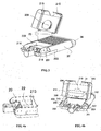
FIG. 1 is a schematic diagram of the LED street lamp of the present invention; -
FIG. 2 is a schematic diagram of the LED street lamp of the present invention as viewed inFIG.1 with opening the cover; -
FIG. 3 is a schematic diagram of the LED street lamp of the present invention as viewed inFIG.1 with disconnecting the cover; -
FIG. 4a is a schematic diagram of the power supply body of the present invention; -
FIG. 4b is a schematic diagram of the disconnected power supply assembly of the present invention; -
FIG. 5a is a schematic diagram of the disconnected street lamp connector of the present invention; -
FIG. 5b is a schematic diagram of the assembled street lamp connector; -
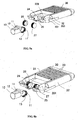
FIG. 6 is a schematic diagram of the assembled light source assembly; -
FIG. 7 is a schematic diagram of the supporting arms of the light source assembly; -
FIG. 8 is a schematic diagram of single light source module of the present invention; -
FIG. 9a is an explosive view of single light source module of the present invention; -
FIG. 9b is a cross-section view of the lens pressing plate of the present invention. - To understand and to practice the present invention, detailed descriptions of the present invention in accompany with the drawings are as follows:
- Referring to
FIG. 1 , a LED street lamp comprises astreet lamp connector 10, apower supply assembly 20 and alight source assembly 30. - Referring to
FIG. 5a and FIG. 5b , thestreet lamp connector 10 is characteristic of hollow T-shape, and two internal toothed rings 12, 13 with locatingslots 11 are respectively provided by two sides of one end of the connector. - Referring to
FIG. 2 andFIG. 3 , thepower supply assembly 20 comprises a power supply body carrying with acover 21 and a circuit module, one end of thecover 21 connects with the power supply body through ahinge 23, and a structure ofcavity 22 is provided by the power supply body. Referring toFIG. 5a and FIG. 5b , one end of the power supply body are provided with twofixation plates screw 28 pierced a screw hole of the external toothed ring to locate in a locatingslot 11 provided by the internal toothed ring to achieve rotatable connection therebetween. - Referring to
FIG. 6 , thelight source assembly 30 comprises two supportingarms side walls light source modules 33 mounted between two said supporting arms, the other end of each of the supportingarms end cover 34 for forming an integrated structure. - Referring to
FIG. 4a, FIG. 4b andFIG. 7 , two half outsidewalls power supply cavity 22 of thepower supply assembly 20 when molding it, twocover side walls cover 21, reinforcingbeams arm 32 which end is fixed to the side wall, is arranged in a space formed by the half outsidewall 203, the reinforcingbeam 207 and theside wall 201, the space is covered and sealed by the cover side wall, likewise, the supportingarm 31 is arranged with the same mounting structures symmetrically on the opposite side. - Referring to
FIG. 3, FIG. 4a and FIG. 4b , the circuit module comprises a light-controllingmodule 208 and apower supply module 209, the light-controllingmodule 208 is mounted in the through-hole 210 provided by thecover 21, and thepower supply module 209 is mounted in thepower supply cavity 22. Two sides of thepower supply module 209 are provided with powersupply fixation plates slots 213, the power supply fixation plates are inserted into the slots to horizontally mount the power supply module on the bottom of thepower supply cavity 22; when thecover 21 is closed, one end of the light-controllingmodule 208 which end is inside thecover 21 is pressed against an upper surface of thepower supply module 209. - Referring to
FIG. 2 andFIG. 3 , thecover 21 hasopenings 215 at the other end thereof,spring plates 214 with hooks are fixed on one end of the power supply body, when thecover 21 is closed, the hooks of thespring plates 214 lock up theopenings 215 so as to fix the cover, after thespring plates 214 have been pressed inward to loosen the hooks, an upward rotation of the cover could make the cover open. - Referring to
FIG. 6 , the supportingarm 31 is a metal tube, and the outer side of the metal tube's cross-section is semicircle shape, the inner side of the supporting arm provides a supportingstep 35 having a plurality of mounting holes. - Referring to
FIG. 8 ,FIG. 9a and FIG. 9b , thelight source module 33 comprises alens pressing plate 301, alens array 302, aLED light board 303 and aradiator 304, theLED light board 303 is mounted on the surface of theradiator 304, thelens array 302 covers the bulbs arranged on theLED light board 303, thelens pressing plate 301 covers the lenses and presses the edges of the lenses, thelens pressing plate 301 has anedge 305 to encircle the sides of theradiator 304, the ends of the radiator have mountingholes 306, which enable the radiator to be mounted on the supportingstep 35 through screws, seeFIG. 6 . - The structural features of the LED street lamp of the present invention will be illustrated in detail.
- The cover provides the light-controlling assembly, the light source module is exposed without housing.
- The power supply cavity has the power supply module mounted therein, and the cavity is sealed by the cover. The cover is provided with the light-controlling module which makes the lamp turn itself off in light environment and turn itself on in the dark. One end of the cover connects with the lamp body through the hinge, and the other end provides the openings, the spring plates with hooks are fixed on one end of the lamp body, when the cover is closed, the hooks of the spring plates lock up the openings so as to fix the cover, see
FIG. 1 . After the spring plates have been pressed inward to loosen the hooks, an upward rotation of the cover could make the cover open. - Referring to
FIG. 4 , Two sides of the power supply module are provided with the power supply fixation plates, while the power supply cavity has the slots, the power supply fixation plates are inserted into the slots to horizontally mount the power supply module on the bottom of the power supply cavity; when the cover is closed, one end of the light-controlling module which end is inside the cover is pressed against the upper surface of the power supply module, while the lower surface of the power supply module is placed on the bottom of the power supply cavity, thus the power supply module is in contacts with the lamp body and is vertically fixed, that is, the power supply module and the lamp body are fixed together without any screw. When there is a need to replace the power supply module, just open the cover first and then remove the power supply module from the slots. - Referring to
FIG. 5 , the connection structure between the street lamp connector and the lamp body comprises the internal toothed rings provided by the street lamp connector, independent external toothed rings and the fixation plates provided by the lamp body for fixing the external toothed rings. The internal toothed rings are molded integrally with the street lamp connector, and the fixation plates for fixing the external toothed rings are molded integrally with the lamp body. When installing these components, the external toothed rings are fixed to the fixation plates first, the external toothed rings are then sleeved with the internal toothed rings, bolts are used to pierce the locating slots as well as the locating holes to locate the connector, thereby the angle between the connector and the lamp body can be kept at a designed degree, alternatively, the external toothed rings could be sleeved with the internal toothed rings first and followed by a fixation though bolts, then the external toothed rings are fixed to the fixation plates. The inner diameter of internal toothed rings is slightly larger than the outer diameter of external toothed rings which facilitates the rotation of them when adjusting angles: The internal toothed rings engage with the external toothed rings at their top to be fixed. - Referring to
FIG. 6 , the light source assembly is consisted of a plurality of light source modules, these modules are arranged side by side between the two supporting arms, and the modules are bridged on the supporting steps of the supporting arms. Tow ends of each light source module are mounted on the supporting steps through screws, and there is no connection between any two light source modules, thereby when some of the modules are being maintained, the other modules would not be affected. Tow ends of each module are mounted on the supporting steps through screws. Referring toFIG. 7 , the supporting arm is a metal tube, and its cross-section is semicircle shape, the supporting arm is fixed to the side wall of the power supply cavity through bolts. The outside surface of the end cover, the half outside walls of the power supply cavity and the half outside walls of the cover all have the curved surfaces that in accordance with the shape of the supporting arms, which makes the fixation of the supporting arms very stable and strong. The length of the supporting arm could be altered when it is designed so as to get the required length, more light source modules could be mounted when there are longer length supporting arms, which decreases the maintenance costs. - Referring to
FIG. 8 ,FIG. 9a and 9b , the light source module comprises the lens pressing plate, the lens array, the LED light board and a radiator. The LED light board is mounted on the surface of the radiator, the lens array covers the bulbs that arranged on the LED light board, the lens pressing plate covers the lenses and presses the edges of the lenses, the lens pressing plate has an edge to encircle the sides of the radiator, which improves the waterproof performance of the LED street lamp. - The power supply assembly independently constitutes an example of the present invention:
- Referring to
FIG. 1 , a LED street lamp comprises astreet lamp connector 10, apower supply assembly 20 and alight source assembly 30. - Referring to
FIG. 5a and FIG. 5b , thestreet lamp connector 10 is characteristic of hollow T-shape, and two internal toothed rings 12, 13 with locatingslots 11 are respectively provided by two sides of one end of the connector. - Referring to
FIG. 2 andFIG. 3 , thepower supply assembly 20 comprises a power supply body carrying with acover 21 and a circuit module, one end of thecover 21 connects with the power supply body through ahinge 23. Referring toFIG. 5a and FIG. 5b , one end of the power supply body are provided with twofixation plates screw 28 pierced a screw hole of the external toothed ring to locate in a locatingslot 11 provided by the internal toothed ring to achieve rotatable connection therebetween. - Referring to
FIG. 6 , thelight source assembly 30 comprises two supportingarms side walls light source modules 33 mounted between two said supporting arms, the other end of each of the supportingarms end cover 34 for forming an integrated structure. - Referring to
FIG. 4a, FIG. 4b andFIG. 7 , two half outsidewalls power supply cavity 22 of thepower supply assembly 20 when molding it, twocover side walls cover 21, reinforcingbeams arm 32 which end is fixed to the side wall, is arranged in a space formed by the half outsidewall 203, the reinforcingbeam 207 and theside wall 201, the space is covered and sealed by the cover side wall, likewise, the supportingarm 31 is arranged with the same mounting structures symmetrically on the opposite side. - Referring to
FIG. 3, FIG. 4a and FIG. 4b , the circuit module comprises a light-controllingmodule 208 and apower supply module 209, the light-controllingmodule 208 is mounted in the through-hole 210 provided by thecover 21, and thepower supply module 209 is mounted in thepower supply cavity 22. Two sides of thepower supply module 209 are provided with powersupply fixation plates slots 213, the power supply fixation plates are inserted into the slots to horizontally mount the power supply module on the bottom of thepower supply cavity 22; when thecover 21 is closed, one end of the light-controllingmodule 208 which end is inside thecover 21 is pressed against an upper surface of thepower supply module 209. - Referring to
FIG. 2 andFIG. 3 , thecover 21 hasopenings 215 at the other end thereof,spring plates 214 with hooks are fixed on one end of the power supply body, when thecover 21 is closed, the hooks of thespring plates 214 lock up theopenings 215 so as to fix the cover, after thespring plates 214 have been pressed inward to loosen the hooks, an upward rotation of the cover could make the cover open. - Referring to
FIG. 6 , the supportingarm 31 is a metal tube, and the outer side of the metal tube's cross-section is semicircle shape, the inner side of the supporting arm provides a supportingstep 35 having a plurality of mounting holes. - The structural features of the LED street lamp of the present invention will be illustrated in detail.
- The cover provides the light-controlling assembly, the light source module is exposed without housing.
- The power supply cavity has the power supply module mounted therein, and the cavity is sealed by the cover. The cover is provided with the light-controlling module which makes the lamp turn itself off in light environment and turn itself on in the dark. One end of the cover connects with the lamp body through the hinge, and the other end provides the openings, the spring plates with hooks are fixed on one end of the lamp body, when the cover is closed, the hooks of the spring plates lock up the openings so as to fix the cover, see
FIG. 1 . After the spring plates have been pressed inward to loosen the hooks, an upward rotation of the cover could make the cover open. - Referring to
FIG. 4 , Two sides of the power supply module are provided with the power supply fixation plates, while the power supply cavity has the slots, the power supply fixation plates are inserted into the slots to horizontally mount the power supply module on the bottom of the power supply cavity; when the cover is closed, one end of the light-controlling module which end is inside the cover is pressed against the upper surface of the power supply module, while the lower surface of the power supply module is placed on the bottom of the power supply cavity, thus the power supply module is in contacts with the lamp body and is vertically fixed, that is, the power supply module and the lamp body are fixed together without any screw. When there is a need to replace the power supply module, just open the cover first and then remove the power supply module from the slots. - Referring to
FIG. 5 , the connection structure between the street lamp connector and the lamp body comprises the internal toothed rings provided by the street lamp connector, independent external toothed rings and the fixation plates provided by the lamp body for fixing the external toothed rings. The internal toothed rings are molded integrally with the street lamp connector, and the fixation plates for fixing the external toothed rings are molded integrally with the lamp body. When installing these components, the external toothed rings are fixed to the fixation plates first, the external toothed rings are then sleeved with the internal toothed rings, bolts are used to pierce the locating slots as well as the locating holes to locate the connector, thereby the angle between the connector and the lamp body can be kept at a designed degree, alternatively, the external toothed rings could be sleeved with the internal toothed rings first and followed by a fixation though bolts, then the external toothed rings are fixed to the fixation plates. The inner diameter of internal toothed rings is slightly larger than the outer diameter of external toothed rings which facilitates the rotation of them when adjusting angles. The internal toothed rings engage with the external toothed rings at their top to be fixed. - Referring to
FIG. 6 , the light source assembly is consisted of a plurality of light source modules, these modules are arranged side by side between the two supporting arms, and the modules are bridged on the supporting steps of the supporting arms. Tow ends of each light source module are mounted on the supporting steps through screws, and there is no connection between any two light source modules, thereby when some of the modules are being maintained, the other modules would not be affected. Tow ends of each module are mounted on the supporting steps through screws. Referring toFIG. 7 , the supporting arm is a metal tube, and its cross-section is semicircle shape, the supporting arm is fixed to the side wall of the power supply cavity through bolts. The outside surface of the end cover, the half outside walls of the power supply cavity and the half outside walls of the cover all have the curved surfaces that in accordance with the shape of the supporting arms, which makes the fixation of the supporting arms very stable and strong. The length of the supporting arm could be altered when it is designed so as to get the required length, more light source modules could be mounted when there are longer length supporting arms, which decreases the maintenance costs. - The supporting arm independently constitutes an example of the present invention:
- Referring to
FIG. 1 , a LED street lamp comprises astreet lamp connector 10, apower supply assembly 20 and alight source assembly 30. - Referring to
FIG. 2 , two half outsidewalls power supply cavity 22 of thepower supply assembly 20 when molding it, twocover side walls cover 21, reinforcingbeams arm 32 which end is fixed to the side wall, is arranged in a space formed by the half outsidewall 203, the reinforcingbeam 207 and theside wall 201, the space is covered and sealed by the cover side wall, likewise, the supportingarm 31 is arranged with the same mounting structures symmetrically on the opposite side. - Referring to
FIG. 6 , thelight source assembly 30 comprises two supportingarms side walls light source modules 33 mounted between two said supporting arms, the other end of each of the supportingarms end cover 34 for forming an integrated structure. - The body of the supporting
arm 31 is presented as a tube, the outer side of its cross-section is semicircle shape, while the inner side of its cross-section is rectangle shape, the rectangle cross-section has a recess thereon to form a supporting step for mounting light source modules, the supporting step is provided with a plurality of mounting holes for mounting the light source modules, one end of the inner side of the rectangle cross-section is provided with a plurality of mounting holes for mounting power supply assembly. The supportingarms 31 could be metal tubes. - At one end of the supporting arm, the inner side of said semicircle is provided with a plurality of mounting holes for mounting the end cover.
- The structural features of the LED street lamp of the present invention will be illustrated in detail.
- The cover provides the light-controlling assembly, the light source module is exposed without housing.
- the light source module comprises a lens pressing plate, a lens array, a LED light board and a radiator, the LED light board is mounted on the surface of the radiator, the lens array covers the bulbs arranged on the LED light board, the lens pressing plate covers the lenses and presses the edges of the lenses, the lens pressing plate has an edge to encircle the sides of the radiator, ends of the radiator have mounting holes which enable the radiator to be mounted on the supporting step through screws.
- Referring to
FIG. 6 , the light source assembly is consisted of a plurality of light source modules, these modules are arranged side by side between the two supporting arms, and the modules are bridged on the supporting steps of the supporting arms. Tow ends of each light source module are mounted on the supporting steps through screws, and there is no connection between any two light source modules, thereby when some of the modules are being maintained, the other modules would not be affected. Tow ends of each module are mounted on the supporting steps through screws. Referring toFIG. 7 , the supporting arm is a metal tube, and its cross-section is semicircle shape, the supporting arm is fixed to the side wall of the power supply cavity through bolts. The outside surface of the end cover, the half outside walls of the power supply cavity and the half outside walls of the cover all have the curved surfaces that in accordance with the shape of the supporting arms, which makes the fixation of the supporting arms very stable and strong. The length of the supporting arm could be altered when it is designed so as to get the required length, more light source modules could be mounted when there are longer length supporting arms, which decreases the maintenance costs. - The light source assembly independently constitutes an example of the present invention:
- Referring to
FIG. 1 , a LED street lamp comprises astreet lamp connector 10, apower supply assembly 20 and alight source assembly 30. - Referring to
FIG. 6 , thelight source assembly 30 comprises two supportingarms side walls light source modules 33 mounted between two said supporting arms, the other end of each of the supportingarms end cover 34 for forming an integrated structure. - Referring to
FIG. 6 , the supportingarm 31 is a metal tube, and the outer side of the metal tube's cross-section is semicircle shape, the inner side of the supporting arm provides a supportingstep 35 having a plurality of mounting holes. - Referring to
FIG. 8 ,FIG. 9a and FIG. 9b , thelight source module 33 comprises alens pressing plate 301, alens array 302, aLED light board 303 and aradiator 304, theLED light board 303 is mounted on the surface of theradiator 304, thelens array 302 covers the bulbs arranged on theLED light board 303, thelens pressing plate 301 covers the lenses and presses the edges of the lenses, thelens pressing plate 301 has anedge 305 to encircle the sides of theradiator 304, the ends of the radiator have mountingholes 306 which enable the radiator to be mounted on the supportingstep 35 through screws, seeFIG. 6 . - The structural features of the LED street lamp of the present invention will be illustrated in detail.
- Referring to
FIG. 6 , the light source assembly is consisted of a plurality of light source modules, these modules are arranged side by side between the two supporting arms, and the modules are bridged on the supporting steps of the supporting arms. Tow ends of each light source module are mounted on the supporting steps through screws, and there is no connection between any two light source modules, thereby when some of the modules are being maintained, the other modules would not be affected. Tow ends of each module are mounted on the supporting steps through screws. Referring toFIG. 7 , the supporting arm is a metal tube, and its cross-section is semicircle shape, the supporting arm is fixed to the side wall of the power supply cavity through bolts. The outside surface of the end cover, the half outside walls of the power supply cavity and the half outside walls of the cover all have the curved surfaces that in accordance with the shape of the supporting arms, which makes the fixation of the supporting arms very stable and strong. The length of the supporting arm could be altered when it is designed so as to get the required length, more light source modules could be mounted when there are longer length supporting arms, which decreases the maintenance costs. - Referring to
FIG. 8 ,FIG. 9a and 9b , the light source module comprises the lens pressing plate, the lens array, the LED light board and a radiator. The LED light board is mounted on the surface of the radiator, the lens array covers the bulbs that arranged on the LED light board, the lens pressing plate covers the lenses and presses the edges of the lenses, the lens pressing plate has an edge to encircle the sides of the radiator, which improves the waterproof performance of the LED street lamp. The radiator is consisted of heat diffusion substrates and a plurality of heat diffusion slices arranged perpendicular to the substrates. The substrate is presented as a cuboid structure. - Industrial applications of the LED street lamp of the present invention.
- The foregoing three examples of the present invention has been presented for the purpose of illustration and description. It is not intended to be exhaustive to limit the invention to the precise form disclosed, and obviously many modifications and variations in regarding to the light source assembly, the power supply assembly and the supporting arms are possible in light of the above teaching. Such modification and variations that may be apparent to those skilled in the art are intended to be included within the scope of this invention as defined by the accompanying claims.
Claims (7)
- A LED street lamp comprising:a power supply assembly 20, comprising a power supply body 22 carrying a cover 21 and a circuit module, one end of the cover 21 being connected with the power supply body 22 through a hinge 23, a structure of power supply cavity with two side walls 200, 201 being formed when molding the power supply body 22, two half outside walls 202, 203 being formed respectively on two sides of the power supply cavity 22 when molding it, two cover side walls 204, 205 in accordance with the shape of the half outside walls being provided by two sides of the cover 21, a reinforcing beam 207 being arranged between the half outside wall 202, 203 and the side wall 200, 201 and being positioned in the middle portion of the half outside 202, 203 wall or the side wall 200, 201 space being formed by the half outside wall,the reinforcing beam and the side wall, the space being covered and sealed by the cover side wall 204, 205;a light source assembly, comprising two supporting arms respectively mounted on the side walls of the power supply cavity and a plurality of light source modules mounted between two said supporting arms, one end of each of the supporting arms being mounted in said space, while the other end being mounted on an end cover for forming an integrated structure; anda street lamp connector, being rotatablely connected to the power supply body at its end.
- The LED street lamp as claimed in claim 1, wherein the street lamp connector characteristic of hollow T-shape, has two internal toothed rings with locating slots respectively provided on two side of one end of the street lamp connector; external toothed rings are mounted on two fixation plates respectively which are arranged on one end of the power supply body, the external toothed rings are sleeved with the internal toothed rings, via a screw pierced a screw hole of the external toothed ring to locate in a locating slot provided by the internal toothed ring to achieve rotatable connection therebetween.
- The LED street lamp as claimed in claim 1 or 2, wherein the cover of the power supply assembly has openings at the other end thereof, spring plates with hooks are fixed on one end of the power supply body, when the cover is closed, the hooks of the spring plates lock up the openings so as to fix the cover, after the spring plates have been pressed inward to loosen the hooks, an upward rotation of the cover could make the cover open.
- The LED street lamp as claimed in claim 1, wherein the circuit module comprises a light-controlling module and a power supply module, the light-controlling module is mounted in a through-hole provided by the cover, and the power supply module is mounted in the power supply cavity.
- The LED street lamp as claimed in claim 4, wherein two sides of the power supply module are provided with power supply fixation plates, while the power supply cavity has slots, the power supply fixation plates are inserted into the slots to horizontally mount the power supply module on the bottom of the power supply cavity; when the cover is closed, one end of the light-controlling module which end is inside the cover is pressed against an upper surface of the power supply module.
- The LED street lamp as claimed in claim 1, wherein the supporting arm is a metal tube, and the outer side of the metal tube's cross-section is semicircle shape, the inner side of the supporting arm provides a supporting step having a plurality of mounting holes.
- The LED street lamp as claimed in claim 6, wherein the light source module comprises a lens pressing plate, a lens array, a LED light board and a radiator, the LED light board is mounted on the surface of the radiator, the lens array covers the bulbs arranged on the LED light board, the lens pressing plate covers the lenses and presses the edges of the lenses, the lens pressing plate has an edge to encircle the sides of the radiator, the ends of the radiator have mounting holes which enable the radiator to be mounted on the supporting step through screws.
Applications Claiming Priority (5)
| Application Number | Priority Date | Filing Date | Title |
|---|---|---|---|
| CN2010202202005U CN201688343U (en) | 2010-06-08 | 2010-06-08 | LED street lamp light source module support arm |
| CN201020220219XU CN201724086U (en) | 2010-06-08 | 2010-06-08 | LED street light source components |
| CN2010202202166U CN201696993U (en) | 2010-06-08 | 2010-06-08 | LED street lamp and power supply assembly and light source assembly of LED street lamp |
| CN2010202202062U CN201706436U (en) | 2010-06-08 | 2010-06-08 | LED street lamp power supply assembly with rotatable joint |
| PCT/CN2010/077609 WO2011153761A1 (en) | 2010-06-08 | 2010-10-09 | Led street lamp |
Publications (3)
| Publication Number | Publication Date |
|---|---|
| EP2581640A1 EP2581640A1 (en) | 2013-04-17 |
| EP2581640A4 EP2581640A4 (en) | 2013-12-25 |
| EP2581640B1 true EP2581640B1 (en) | 2015-11-04 |
Family
ID=45097484
Family Applications (1)
| Application Number | Title | Priority Date | Filing Date |
|---|---|---|---|
| EP10852753.2A Not-in-force EP2581640B1 (en) | 2010-06-08 | 2010-10-09 | Led street lamp |
Country Status (11)
| Country | Link |
|---|---|
| US (1) | US8708526B2 (en) |
| EP (1) | EP2581640B1 (en) |
| JP (1) | JP5547850B2 (en) |
| KR (1) | KR101483841B1 (en) |
| BR (1) | BR112012030879B1 (en) |
| CA (1) | CA2801616C (en) |
| CL (1) | CL2012003472A1 (en) |
| ES (1) | ES2554483T3 (en) |
| MX (1) | MX2012014220A (en) |
| MY (1) | MY164271A (en) |
| WO (1) | WO2011153761A1 (en) |
Families Citing this family (35)
| Publication number | Priority date | Publication date | Assignee | Title |
|---|---|---|---|---|
| SE537327C2 (en) | 2012-02-01 | 2015-04-07 | Strihl Scandinavia Ab | Easy mountable lighting fixture with fitting device |
| KR20130099300A (en) * | 2012-02-29 | 2013-09-06 | (주)유민에쓰티 | Capacitive Water Level Sensor |
| JP6276495B2 (en) * | 2012-03-26 | 2018-02-07 | 東芝ライテック株式会社 | Lighting device |
| US10215378B2 (en) * | 2012-04-13 | 2019-02-26 | Cree, Inc. | Light fixture |
| JP5966795B2 (en) * | 2012-09-14 | 2016-08-10 | 岩崎電気株式会社 | lighting equipment |
| CN104165339A (en) * | 2013-05-17 | 2014-11-26 | 全亿大科技(佛山)有限公司 | LED (light emitting diode) illuminating lamp |
| USD770317S1 (en) * | 2013-07-19 | 2016-11-01 | Weidmueller Interface Gmbh & Co. Kg | LED lights |
| KR101457407B1 (en) * | 2013-11-22 | 2014-11-07 | 주식회사 명신전자 | Led lighting apparatus with divided installed converter |
| KR101595905B1 (en) * | 2013-12-03 | 2016-02-23 | 박인철 | Rotational streetlighting apparatus |
| KR101423501B1 (en) * | 2013-12-05 | 2014-07-28 | (주) 비에치엘나노텍 | lighting lamp |
| DE102014103699A1 (en) * | 2014-03-18 | 2015-09-24 | Trilux Gmbh & Co. Kg | pole mounting |
| KR101466160B1 (en) * | 2014-06-12 | 2014-11-28 | 주식회사 디케이조명 | LED Tunnel Luminaire |
| KR101714441B1 (en) * | 2014-08-12 | 2017-03-09 | 엘지전자 주식회사 | Lighting apparatus |
| CN105782837A (en) * | 2014-12-22 | 2016-07-20 | 欧普照明股份有限公司 | Lamp |
| USD754385S1 (en) | 2015-03-24 | 2016-04-19 | Atlas Lighting Products, Inc. | LED area light fixture |
| US9777910B2 (en) | 2015-03-24 | 2017-10-03 | Atlas Lighting Products, Inc. | LED based area lighting fixture |
| KR101613899B1 (en) | 2015-06-03 | 2016-04-21 | 주식회사 삼광산전 | Led lighting device capable of changing luminous quantity and supporter by assembly block structure |
| JP6725315B2 (en) * | 2016-05-17 | 2020-07-15 | 株式会社因幡電機製作所 | Lighting fixture mounting structure |
| CN107975734B (en) * | 2016-10-21 | 2023-03-24 | 宁波兴莱达灯具有限公司 | Street lamp |
| CN109488955A (en) * | 2016-11-25 | 2019-03-19 | 南通溢德行工业科技有限公司 | LED street lamp |
| KR101819859B1 (en) * | 2017-05-30 | 2018-01-17 | 재단법인 한국탄소융합기술원 | A led street lamp manufacturing method |
| KR101968824B1 (en) * | 2017-07-11 | 2019-04-12 | 재단법인 한국탄소융합기술원 | A led street lamp |
| CN207501024U (en) * | 2017-09-08 | 2018-06-15 | 东莞市泰亮半导体照明有限公司 | A solar lamp |
| KR102036692B1 (en) * | 2017-12-29 | 2019-10-25 | 조광섭 | Lights with adjustable up and down angle included in street lights and security lights |
| CN108233679A (en) * | 2018-01-11 | 2018-06-29 | 西蒙电气(中国)有限公司 | Modularization intelligent lamp power installing mechanism and matching PCB components |
| USD919868S1 (en) * | 2018-06-25 | 2021-05-18 | Zopoise Technology (Zhuzhou) Co., Ltd. | Street lamp |
| CN108895342A (en) * | 2018-07-24 | 2018-11-27 | 江门沃能光电科技有限公司 | A kind of light-operated LED road lamp |
| CN109084236B (en) * | 2018-08-17 | 2023-12-01 | 杭州中港数码技术有限公司 | LED street lamp |
| EP3853523B1 (en) * | 2018-09-19 | 2022-11-09 | Signify Holding B.V. | Luminaire mounting |
| DE202018106344U1 (en) * | 2018-11-08 | 2018-11-14 | Karl Leibinger Medizintechnik Gmbh & Co. Kg | Surgical lights housing |
| DE102018131419A1 (en) * | 2018-12-07 | 2020-06-10 | Trilux Gmbh & Co. Kg | Luminaire with fastening device for mast mounting |
| CN110822348B (en) * | 2019-12-13 | 2024-08-02 | 江门市万翊照明有限公司 | Diversion type projection lamp |
| US12345407B2 (en) * | 2023-07-03 | 2025-07-01 | Leedarson Lighting Co., Ltd. | Lighting apparatus |
| CN116972365A (en) * | 2023-09-11 | 2023-10-31 | 深圳市亿加能实业有限公司 | A lighting fixture that is easy to disassemble and assemble |
| CN118793980B (en) * | 2024-08-20 | 2025-03-18 | 星慧照明工程集团有限公司 | Modular lens LED street lamp |
Family Cites Families (11)
| Publication number | Priority date | Publication date | Assignee | Title |
|---|---|---|---|---|
| JP4564917B2 (en) * | 2005-12-12 | 2010-10-20 | 株式会社東亜製作所 | LED lighting |
| JP2009209540A (en) * | 2008-03-03 | 2009-09-17 | Autech Japan Inc | Hinge structure of door for vehicle |
| JP3141766U (en) * | 2008-03-05 | 2008-05-22 | 有限会社ユークラフト | Lighting device |
| FR2937401B1 (en) * | 2008-10-17 | 2013-05-24 | Eclatec | FIXING BALL OF AN URBAN LIGHTING LANTERN ON A SUPPORT COMPRISING AN INCLINATION ADJUSTMENT AND AN AUTOMATIC SHUTTERING OF A PASSAGE FOR THE SUPPORT |
| CN201348165Y (en) * | 2009-01-13 | 2009-11-18 | 广东昭信金属制品有限公司 | Mounting structure for multi-cavity integrative LED lamp |
| CN101482241A (en) * | 2009-02-05 | 2009-07-15 | 史杰 | LED module road lamp cap with adjustable irradiation angle and high radiation capability. |
| DE202009003239U1 (en) * | 2009-03-06 | 2009-07-02 | Autev Ag | Luminaire with swiveling light wings |
| CN201412734Y (en) * | 2009-06-01 | 2010-02-24 | 史杰 | LED modular streetlamp lamp holder with adjustable illumination angle |
| KR200447348Y1 (en) * | 2009-07-03 | 2010-01-22 | 박영민 | Lighting angle control device for street light |
| CN201475921U (en) * | 2009-09-08 | 2010-05-19 | 东莞超速科技拓展有限公司 | Novel lamp switching device |
| CN102454919A (en) * | 2010-10-20 | 2012-05-16 | 富准精密工业(深圳)有限公司 | LED lamp |
-
2010
- 2010-10-09 JP JP2013513519A patent/JP5547850B2/en not_active Expired - Fee Related
- 2010-10-09 BR BR112012030879-3A patent/BR112012030879B1/en not_active IP Right Cessation
- 2010-10-09 WO PCT/CN2010/077609 patent/WO2011153761A1/en not_active Ceased
- 2010-10-09 US US13/702,581 patent/US8708526B2/en not_active Expired - Fee Related
- 2010-10-09 MY MYPI2012005231A patent/MY164271A/en unknown
- 2010-10-09 MX MX2012014220A patent/MX2012014220A/en active IP Right Grant
- 2010-10-09 KR KR1020127031817A patent/KR101483841B1/en not_active Expired - Fee Related
- 2010-10-09 EP EP10852753.2A patent/EP2581640B1/en not_active Not-in-force
- 2010-10-09 CA CA2801616A patent/CA2801616C/en not_active Expired - Fee Related
- 2010-10-09 ES ES10852753.2T patent/ES2554483T3/en active Active
-
2012
- 2012-12-07 CL CL2012003472A patent/CL2012003472A1/en unknown
Also Published As
| Publication number | Publication date |
|---|---|
| CL2012003472A1 (en) | 2013-08-02 |
| EP2581640A4 (en) | 2013-12-25 |
| CA2801616A1 (en) | 2011-12-15 |
| JP5547850B2 (en) | 2014-07-16 |
| KR101483841B1 (en) | 2015-01-26 |
| JP2013546113A (en) | 2013-12-26 |
| CA2801616C (en) | 2015-04-14 |
| MX2012014220A (en) | 2013-02-11 |
| WO2011153761A1 (en) | 2011-12-15 |
| ES2554483T3 (en) | 2015-12-21 |
| US20130088861A1 (en) | 2013-04-11 |
| BR112012030879B1 (en) | 2019-09-24 |
| MY164271A (en) | 2017-11-30 |
| EP2581640A1 (en) | 2013-04-17 |
| US8708526B2 (en) | 2014-04-29 |
| KR20130016356A (en) | 2013-02-14 |
| BR112012030879A2 (en) | 2016-11-08 |
Similar Documents
| Publication | Publication Date | Title |
|---|---|---|
| US8708526B2 (en) | LED street lamp | |
| US20210172592A1 (en) | Ceiling lamp | |
| WO2013165768A1 (en) | Led light fixture | |
| WO2021004084A1 (en) | Solar street lamp | |
| CN211925550U (en) | Lamp fitting | |
| CN205402432U (en) | Lighting device | |
| EP3572713B1 (en) | Lamp | |
| WO2016037581A1 (en) | Led linear lamp and combined lens apparatus thereof | |
| WO2015185007A1 (en) | Lamp | |
| JP6377859B2 (en) | Power unit direct-coupled LR lighting system | |
| CN102054403B (en) | Display screen maintained from front end | |
| CN207471318U (en) | Illumination module and lamps and lanterns | |
| WO2015063805A1 (en) | Public or street led lighting apparatus comprising a pair of watertight cable clamps | |
| CN214840447U (en) | High-power LED high shed lamp | |
| CN209801274U (en) | Plant growth lamp | |
| CN207438187U (en) | A kind of LED light | |
| CN204141515U (en) | A kind of self-locking reflector module and lighting | |
| CN222706740U (en) | LED power supply shell and LED power supply using same | |
| CN220981256U (en) | Quick-release structure of LED lamp driving assembly and ceiling lamp | |
| CN214425732U (en) | Healthy light source group mounting structure of LED chip | |
| CN216047250U (en) | Biological optical lamp of section bar octopus | |
| CN218671920U (en) | Plant growing lamp | |
| CN221258732U (en) | High-pole lamp | |
| CN110107834B (en) | Lighting lamp | |
| CN216897230U (en) | Lamp set |
Legal Events
| Date | Code | Title | Description |
|---|---|---|---|
| PUAI | Public reference made under article 153(3) epc to a published international application that has entered the european phase |
Free format text: ORIGINAL CODE: 0009012 |
|
| 17P | Request for examination filed |
Effective date: 20130103 |
|
| AK | Designated contracting states |
Kind code of ref document: A1 Designated state(s): AL AT BE BG CH CY CZ DE DK EE ES FI FR GB GR HR HU IE IS IT LI LT LU LV MC MK MT NL NO PL PT RO RS SE SI SK SM TR |
|
| DAX | Request for extension of the european patent (deleted) | ||
| A4 | Supplementary search report drawn up and despatched |
Effective date: 20131121 |
|
| RIC1 | Information provided on ipc code assigned before grant |
Ipc: F21V 23/00 20060101ALI20131115BHEP Ipc: F21S 2/00 20060101AFI20131115BHEP Ipc: F21V 21/14 20060101ALI20131115BHEP Ipc: F21V 19/00 20060101ALI20131115BHEP Ipc: F21Y 101/02 20060101ALI20131115BHEP Ipc: F21K 99/00 20100101ALI20131115BHEP |
|
| RIC1 | Information provided on ipc code assigned before grant |
Ipc: F21K 99/00 20100101ALI20150211BHEP Ipc: F21S 2/00 20060101AFI20150211BHEP Ipc: F21V 23/00 20150101ALI20150211BHEP Ipc: F21V 21/14 20060101ALI20150211BHEP Ipc: F21Y 101/02 20060101ALI20150211BHEP Ipc: F21V 19/00 20060101ALI20150211BHEP |
|
| GRAP | Despatch of communication of intention to grant a patent |
Free format text: ORIGINAL CODE: EPIDOSNIGR1 |
|
| INTG | Intention to grant announced |
Effective date: 20150507 |
|
| GRAS | Grant fee paid |
Free format text: ORIGINAL CODE: EPIDOSNIGR3 |
|
| GRAA | (expected) grant |
Free format text: ORIGINAL CODE: 0009210 |
|
| AK | Designated contracting states |
Kind code of ref document: B1 Designated state(s): AL AT BE BG CH CY CZ DE DK EE ES FI FR GB GR HR HU IE IS IT LI LT LU LV MC MK MT NL NO PL PT RO RS SE SI SK SM TR |
|
| REG | Reference to a national code |
Ref country code: GB Ref legal event code: FG4D |
|
| REG | Reference to a national code |
Ref country code: CH Ref legal event code: EP |
|
| REG | Reference to a national code |
Ref country code: AT Ref legal event code: REF Ref document number: 759459 Country of ref document: AT Kind code of ref document: T Effective date: 20151115 |
|
| REG | Reference to a national code |
Ref country code: IE Ref legal event code: FG4D |
|
| REG | Reference to a national code |
Ref country code: DE Ref legal event code: R096 Ref document number: 602010028883 Country of ref document: DE |
|
| REG | Reference to a national code |
Ref country code: ES Ref legal event code: FG2A Ref document number: 2554483 Country of ref document: ES Kind code of ref document: T3 Effective date: 20151221 |
|
| REG | Reference to a national code |
Ref country code: NL Ref legal event code: MP Effective date: 20151104 |
|
| REG | Reference to a national code |
Ref country code: LT Ref legal event code: MG4D |
|
| REG | Reference to a national code |
Ref country code: AT Ref legal event code: MK05 Ref document number: 759459 Country of ref document: AT Kind code of ref document: T Effective date: 20151104 |
|
| PG25 | Lapsed in a contracting state [announced via postgrant information from national office to epo] |
Ref country code: HR Free format text: LAPSE BECAUSE OF FAILURE TO SUBMIT A TRANSLATION OF THE DESCRIPTION OR TO PAY THE FEE WITHIN THE PRESCRIBED TIME-LIMIT Effective date: 20151104 Ref country code: NO Free format text: LAPSE BECAUSE OF FAILURE TO SUBMIT A TRANSLATION OF THE DESCRIPTION OR TO PAY THE FEE WITHIN THE PRESCRIBED TIME-LIMIT Effective date: 20160204 Ref country code: IT Free format text: LAPSE BECAUSE OF FAILURE TO SUBMIT A TRANSLATION OF THE DESCRIPTION OR TO PAY THE FEE WITHIN THE PRESCRIBED TIME-LIMIT Effective date: 20151104 Ref country code: IS Free format text: LAPSE BECAUSE OF FAILURE TO SUBMIT A TRANSLATION OF THE DESCRIPTION OR TO PAY THE FEE WITHIN THE PRESCRIBED TIME-LIMIT Effective date: 20160304 Ref country code: LT Free format text: LAPSE BECAUSE OF FAILURE TO SUBMIT A TRANSLATION OF THE DESCRIPTION OR TO PAY THE FEE WITHIN THE PRESCRIBED TIME-LIMIT Effective date: 20151104 Ref country code: NL Free format text: LAPSE BECAUSE OF FAILURE TO SUBMIT A TRANSLATION OF THE DESCRIPTION OR TO PAY THE FEE WITHIN THE PRESCRIBED TIME-LIMIT Effective date: 20151104 |
|
| PG25 | Lapsed in a contracting state [announced via postgrant information from national office to epo] |
Ref country code: PL Free format text: LAPSE BECAUSE OF FAILURE TO SUBMIT A TRANSLATION OF THE DESCRIPTION OR TO PAY THE FEE WITHIN THE PRESCRIBED TIME-LIMIT Effective date: 20151104 Ref country code: LV Free format text: LAPSE BECAUSE OF FAILURE TO SUBMIT A TRANSLATION OF THE DESCRIPTION OR TO PAY THE FEE WITHIN THE PRESCRIBED TIME-LIMIT Effective date: 20151104 Ref country code: RS Free format text: LAPSE BECAUSE OF FAILURE TO SUBMIT A TRANSLATION OF THE DESCRIPTION OR TO PAY THE FEE WITHIN THE PRESCRIBED TIME-LIMIT Effective date: 20151104 Ref country code: FI Free format text: LAPSE BECAUSE OF FAILURE TO SUBMIT A TRANSLATION OF THE DESCRIPTION OR TO PAY THE FEE WITHIN THE PRESCRIBED TIME-LIMIT Effective date: 20151104 Ref country code: AT Free format text: LAPSE BECAUSE OF FAILURE TO SUBMIT A TRANSLATION OF THE DESCRIPTION OR TO PAY THE FEE WITHIN THE PRESCRIBED TIME-LIMIT Effective date: 20151104 Ref country code: SE Free format text: LAPSE BECAUSE OF FAILURE TO SUBMIT A TRANSLATION OF THE DESCRIPTION OR TO PAY THE FEE WITHIN THE PRESCRIBED TIME-LIMIT Effective date: 20151104 Ref country code: GR Free format text: LAPSE BECAUSE OF FAILURE TO SUBMIT A TRANSLATION OF THE DESCRIPTION OR TO PAY THE FEE WITHIN THE PRESCRIBED TIME-LIMIT Effective date: 20160205 Ref country code: PT Free format text: LAPSE BECAUSE OF FAILURE TO SUBMIT A TRANSLATION OF THE DESCRIPTION OR TO PAY THE FEE WITHIN THE PRESCRIBED TIME-LIMIT Effective date: 20160304 |
|
| PG25 | Lapsed in a contracting state [announced via postgrant information from national office to epo] |
Ref country code: CZ Free format text: LAPSE BECAUSE OF FAILURE TO SUBMIT A TRANSLATION OF THE DESCRIPTION OR TO PAY THE FEE WITHIN THE PRESCRIBED TIME-LIMIT Effective date: 20151104 |
|
| REG | Reference to a national code |
Ref country code: DE Ref legal event code: R097 Ref document number: 602010028883 Country of ref document: DE |
|
| PG25 | Lapsed in a contracting state [announced via postgrant information from national office to epo] |
Ref country code: SK Free format text: LAPSE BECAUSE OF FAILURE TO SUBMIT A TRANSLATION OF THE DESCRIPTION OR TO PAY THE FEE WITHIN THE PRESCRIBED TIME-LIMIT Effective date: 20151104 Ref country code: DK Free format text: LAPSE BECAUSE OF FAILURE TO SUBMIT A TRANSLATION OF THE DESCRIPTION OR TO PAY THE FEE WITHIN THE PRESCRIBED TIME-LIMIT Effective date: 20151104 Ref country code: RO Free format text: LAPSE BECAUSE OF FAILURE TO SUBMIT A TRANSLATION OF THE DESCRIPTION OR TO PAY THE FEE WITHIN THE PRESCRIBED TIME-LIMIT Effective date: 20151104 Ref country code: SM Free format text: LAPSE BECAUSE OF FAILURE TO SUBMIT A TRANSLATION OF THE DESCRIPTION OR TO PAY THE FEE WITHIN THE PRESCRIBED TIME-LIMIT Effective date: 20151104 Ref country code: EE Free format text: LAPSE BECAUSE OF FAILURE TO SUBMIT A TRANSLATION OF THE DESCRIPTION OR TO PAY THE FEE WITHIN THE PRESCRIBED TIME-LIMIT Effective date: 20151104 |
|
| PLBE | No opposition filed within time limit |
Free format text: ORIGINAL CODE: 0009261 |
|
| STAA | Information on the status of an ep patent application or granted ep patent |
Free format text: STATUS: NO OPPOSITION FILED WITHIN TIME LIMIT |
|
| 26N | No opposition filed |
Effective date: 20160805 |
|
| PG25 | Lapsed in a contracting state [announced via postgrant information from national office to epo] |
Ref country code: SI Free format text: LAPSE BECAUSE OF FAILURE TO SUBMIT A TRANSLATION OF THE DESCRIPTION OR TO PAY THE FEE WITHIN THE PRESCRIBED TIME-LIMIT Effective date: 20151104 |
|
| PG25 | Lapsed in a contracting state [announced via postgrant information from national office to epo] |
Ref country code: BE Free format text: LAPSE BECAUSE OF FAILURE TO SUBMIT A TRANSLATION OF THE DESCRIPTION OR TO PAY THE FEE WITHIN THE PRESCRIBED TIME-LIMIT Effective date: 20151104 |
|
| REG | Reference to a national code |
Ref country code: CH Ref legal event code: PL |
|
| PG25 | Lapsed in a contracting state [announced via postgrant information from national office to epo] |
Ref country code: MC Free format text: LAPSE BECAUSE OF FAILURE TO SUBMIT A TRANSLATION OF THE DESCRIPTION OR TO PAY THE FEE WITHIN THE PRESCRIBED TIME-LIMIT Effective date: 20151104 |
|
| REG | Reference to a national code |
Ref country code: IE Ref legal event code: MM4A |
|
| REG | Reference to a national code |
Ref country code: FR Ref legal event code: ST Effective date: 20170630 |
|
| PG25 | Lapsed in a contracting state [announced via postgrant information from national office to epo] |
Ref country code: LI Free format text: LAPSE BECAUSE OF NON-PAYMENT OF DUE FEES Effective date: 20161031 Ref country code: FR Free format text: LAPSE BECAUSE OF NON-PAYMENT OF DUE FEES Effective date: 20161102 Ref country code: CH Free format text: LAPSE BECAUSE OF NON-PAYMENT OF DUE FEES Effective date: 20161031 |
|
| PG25 | Lapsed in a contracting state [announced via postgrant information from national office to epo] |
Ref country code: LU Free format text: LAPSE BECAUSE OF NON-PAYMENT OF DUE FEES Effective date: 20161009 |
|
| PG25 | Lapsed in a contracting state [announced via postgrant information from national office to epo] |
Ref country code: IE Free format text: LAPSE BECAUSE OF NON-PAYMENT OF DUE FEES Effective date: 20161009 |
|
| REG | Reference to a national code |
Ref country code: GB Ref legal event code: 732E Free format text: REGISTERED BETWEEN 20180308 AND 20180314 |
|
| REG | Reference to a national code |
Ref country code: DE Ref legal event code: R082 Ref document number: 602010028883 Country of ref document: DE Representative=s name: DOMPATENT VON KREISLER SELTING WERNER - PARTNE, DE Ref country code: DE Ref legal event code: R081 Ref document number: 602010028883 Country of ref document: DE Owner name: KINGSUN OPTOELECTRONIC CO., LTD., DONGGUANG, CN Free format text: FORMER OWNER: DONGGUAN KINGSUN OPTOELECTRONIC CO., LTD, DONGGUAN, GUANGDONG, CN |
|
| PG25 | Lapsed in a contracting state [announced via postgrant information from national office to epo] |
Ref country code: CY Free format text: LAPSE BECAUSE OF FAILURE TO SUBMIT A TRANSLATION OF THE DESCRIPTION OR TO PAY THE FEE WITHIN THE PRESCRIBED TIME-LIMIT Effective date: 20151104 Ref country code: HU Free format text: LAPSE BECAUSE OF FAILURE TO SUBMIT A TRANSLATION OF THE DESCRIPTION OR TO PAY THE FEE WITHIN THE PRESCRIBED TIME-LIMIT; INVALID AB INITIO Effective date: 20101009 |
|
| REG | Reference to a national code |
Ref country code: ES Ref legal event code: PC2A Effective date: 20180525 Ref country code: ES Ref legal event code: PC2A Owner name: KINGSUN OPTOELECTRONIC CO., LTD Effective date: 20180525 |
|
| PG25 | Lapsed in a contracting state [announced via postgrant information from national office to epo] |
Ref country code: MK Free format text: LAPSE BECAUSE OF FAILURE TO SUBMIT A TRANSLATION OF THE DESCRIPTION OR TO PAY THE FEE WITHIN THE PRESCRIBED TIME-LIMIT Effective date: 20151104 Ref country code: TR Free format text: LAPSE BECAUSE OF FAILURE TO SUBMIT A TRANSLATION OF THE DESCRIPTION OR TO PAY THE FEE WITHIN THE PRESCRIBED TIME-LIMIT Effective date: 20151104 Ref country code: MT Free format text: LAPSE BECAUSE OF NON-PAYMENT OF DUE FEES Effective date: 20161031 |
|
| PG25 | Lapsed in a contracting state [announced via postgrant information from national office to epo] |
Ref country code: BG Free format text: LAPSE BECAUSE OF FAILURE TO SUBMIT A TRANSLATION OF THE DESCRIPTION OR TO PAY THE FEE WITHIN THE PRESCRIBED TIME-LIMIT Effective date: 20151104 |
|
| PG25 | Lapsed in a contracting state [announced via postgrant information from national office to epo] |
Ref country code: AL Free format text: LAPSE BECAUSE OF FAILURE TO SUBMIT A TRANSLATION OF THE DESCRIPTION OR TO PAY THE FEE WITHIN THE PRESCRIBED TIME-LIMIT Effective date: 20151104 |
|
| PGFP | Annual fee paid to national office [announced via postgrant information from national office to epo] |
Ref country code: GB Payment date: 20180917 Year of fee payment: 9 |
|
| PGFP | Annual fee paid to national office [announced via postgrant information from national office to epo] |
Ref country code: DE Payment date: 20181031 Year of fee payment: 9 |
|
| RIC2 | Information provided on ipc code assigned after grant |
Ipc: F21V 19/00 20060101ALI20150211BHEP Ipc: F21Y 101/02 20000101ALI20150211BHEP Ipc: F21V 21/14 20060101ALI20150211BHEP Ipc: F21K 99/00 20160101ALI20150211BHEP Ipc: F21S 2/00 20160101AFI20150211BHEP Ipc: F21V 23/00 20150101ALI20150211BHEP |
|
| PGFP | Annual fee paid to national office [announced via postgrant information from national office to epo] |
Ref country code: ES Payment date: 20181122 Year of fee payment: 9 |
|
| REG | Reference to a national code |
Ref country code: DE Ref legal event code: R119 Ref document number: 602010028883 Country of ref document: DE |
|
| PG25 | Lapsed in a contracting state [announced via postgrant information from national office to epo] |
Ref country code: DE Free format text: LAPSE BECAUSE OF NON-PAYMENT OF DUE FEES Effective date: 20200501 |
|
| GBPC | Gb: european patent ceased through non-payment of renewal fee |
Effective date: 20191009 |
|
| PG25 | Lapsed in a contracting state [announced via postgrant information from national office to epo] |
Ref country code: GB Free format text: LAPSE BECAUSE OF NON-PAYMENT OF DUE FEES Effective date: 20191009 |
|
| REG | Reference to a national code |
Ref country code: ES Ref legal event code: FD2A Effective date: 20210303 |
|
| PG25 | Lapsed in a contracting state [announced via postgrant information from national office to epo] |
Ref country code: ES Free format text: LAPSE BECAUSE OF NON-PAYMENT OF DUE FEES Effective date: 20191010 |