EP2581574A1 - Intra-exhaust-pipe fuel-injection system - Google Patents
Intra-exhaust-pipe fuel-injection system Download PDFInfo
- Publication number
- EP2581574A1 EP2581574A1 EP11792549.5A EP11792549A EP2581574A1 EP 2581574 A1 EP2581574 A1 EP 2581574A1 EP 11792549 A EP11792549 A EP 11792549A EP 2581574 A1 EP2581574 A1 EP 2581574A1
- Authority
- EP
- European Patent Office
- Prior art keywords
- exhaust
- exhaust pipe
- fuel
- adaptor
- dpf
- Prior art date
- Legal status (The legal status is an assumption and is not a legal conclusion. Google has not performed a legal analysis and makes no representation as to the accuracy of the status listed.)
- Granted
Links
Images

Classifications
-
- F—MECHANICAL ENGINEERING; LIGHTING; HEATING; WEAPONS; BLASTING
- F01—MACHINES OR ENGINES IN GENERAL; ENGINE PLANTS IN GENERAL; STEAM ENGINES
- F01N—GAS-FLOW SILENCERS OR EXHAUST APPARATUS FOR MACHINES OR ENGINES IN GENERAL; GAS-FLOW SILENCERS OR EXHAUST APPARATUS FOR INTERNAL-COMBUSTION ENGINES
- F01N3/00—Exhaust or silencing apparatus having means for purifying, rendering innocuous, or otherwise treating exhaust
- F01N3/02—Exhaust or silencing apparatus having means for purifying, rendering innocuous, or otherwise treating exhaust for cooling, or for removing solid constituents of, exhaust
- F01N3/021—Exhaust or silencing apparatus having means for purifying, rendering innocuous, or otherwise treating exhaust for cooling, or for removing solid constituents of, exhaust by means of filters
- F01N3/023—Exhaust or silencing apparatus having means for purifying, rendering innocuous, or otherwise treating exhaust for cooling, or for removing solid constituents of, exhaust by means of filters using means for regenerating the filters, e.g. by burning trapped particles
- F01N3/025—Exhaust or silencing apparatus having means for purifying, rendering innocuous, or otherwise treating exhaust for cooling, or for removing solid constituents of, exhaust by means of filters using means for regenerating the filters, e.g. by burning trapped particles using fuel burner or by adding fuel to exhaust
- F01N3/0253—Exhaust or silencing apparatus having means for purifying, rendering innocuous, or otherwise treating exhaust for cooling, or for removing solid constituents of, exhaust by means of filters using means for regenerating the filters, e.g. by burning trapped particles using fuel burner or by adding fuel to exhaust adding fuel to exhaust gases
-
- F—MECHANICAL ENGINEERING; LIGHTING; HEATING; WEAPONS; BLASTING
- F01—MACHINES OR ENGINES IN GENERAL; ENGINE PLANTS IN GENERAL; STEAM ENGINES
- F01N—GAS-FLOW SILENCERS OR EXHAUST APPARATUS FOR MACHINES OR ENGINES IN GENERAL; GAS-FLOW SILENCERS OR EXHAUST APPARATUS FOR INTERNAL-COMBUSTION ENGINES
- F01N13/00—Exhaust or silencing apparatus characterised by constructional features
- F01N13/08—Other arrangements or adaptations of exhaust conduits
-
- F—MECHANICAL ENGINEERING; LIGHTING; HEATING; WEAPONS; BLASTING
- F01—MACHINES OR ENGINES IN GENERAL; ENGINE PLANTS IN GENERAL; STEAM ENGINES
- F01N—GAS-FLOW SILENCERS OR EXHAUST APPARATUS FOR MACHINES OR ENGINES IN GENERAL; GAS-FLOW SILENCERS OR EXHAUST APPARATUS FOR INTERNAL-COMBUSTION ENGINES
- F01N13/00—Exhaust or silencing apparatus characterised by constructional features
- F01N13/18—Construction facilitating manufacture, assembly, or disassembly
- F01N13/1805—Fixing exhaust manifolds, exhaust pipes or pipe sections to each other, to engine or to vehicle body
-
- F—MECHANICAL ENGINEERING; LIGHTING; HEATING; WEAPONS; BLASTING
- F01—MACHINES OR ENGINES IN GENERAL; ENGINE PLANTS IN GENERAL; STEAM ENGINES
- F01N—GAS-FLOW SILENCERS OR EXHAUST APPARATUS FOR MACHINES OR ENGINES IN GENERAL; GAS-FLOW SILENCERS OR EXHAUST APPARATUS FOR INTERNAL-COMBUSTION ENGINES
- F01N3/00—Exhaust or silencing apparatus having means for purifying, rendering innocuous, or otherwise treating exhaust
- F01N3/08—Exhaust or silencing apparatus having means for purifying, rendering innocuous, or otherwise treating exhaust for rendering innocuous
- F01N3/10—Exhaust or silencing apparatus having means for purifying, rendering innocuous, or otherwise treating exhaust for rendering innocuous by thermal or catalytic conversion of noxious components of exhaust
- F01N3/24—Exhaust or silencing apparatus having means for purifying, rendering innocuous, or otherwise treating exhaust for rendering innocuous by thermal or catalytic conversion of noxious components of exhaust characterised by constructional aspects of converting apparatus
- F01N3/36—Arrangements for supply of additional fuel
-
- B—PERFORMING OPERATIONS; TRANSPORTING
- B01—PHYSICAL OR CHEMICAL PROCESSES OR APPARATUS IN GENERAL
- B01D—SEPARATION
- B01D53/00—Separation of gases or vapours; Recovering vapours of volatile solvents from gases; Chemical or biological purification of waste gases, e.g. engine exhaust gases, smoke, fumes, flue gases, aerosols
- B01D53/34—Chemical or biological purification of waste gases
- B01D53/92—Chemical or biological purification of waste gases of engine exhaust gases
- B01D53/94—Chemical or biological purification of waste gases of engine exhaust gases by catalytic processes
- B01D53/9459—Removing one or more of nitrogen oxides, carbon monoxide, or hydrocarbons by multiple successive catalytic functions; systems with more than one different function, e.g. zone coated catalysts
- B01D53/9477—Removing one or more of nitrogen oxides, carbon monoxide, or hydrocarbons by multiple successive catalytic functions; systems with more than one different function, e.g. zone coated catalysts with catalysts positioned on separate bricks, e.g. exhaust systems
-
- F—MECHANICAL ENGINEERING; LIGHTING; HEATING; WEAPONS; BLASTING
- F01—MACHINES OR ENGINES IN GENERAL; ENGINE PLANTS IN GENERAL; STEAM ENGINES
- F01N—GAS-FLOW SILENCERS OR EXHAUST APPARATUS FOR MACHINES OR ENGINES IN GENERAL; GAS-FLOW SILENCERS OR EXHAUST APPARATUS FOR INTERNAL-COMBUSTION ENGINES
- F01N13/00—Exhaust or silencing apparatus characterised by constructional features
- F01N13/18—Construction facilitating manufacture, assembly, or disassembly
- F01N13/1805—Fixing exhaust manifolds, exhaust pipes or pipe sections to each other, to engine or to vehicle body
- F01N13/1827—Sealings specially adapted for exhaust systems
-
- F—MECHANICAL ENGINEERING; LIGHTING; HEATING; WEAPONS; BLASTING
- F01—MACHINES OR ENGINES IN GENERAL; ENGINE PLANTS IN GENERAL; STEAM ENGINES
- F01N—GAS-FLOW SILENCERS OR EXHAUST APPARATUS FOR MACHINES OR ENGINES IN GENERAL; GAS-FLOW SILENCERS OR EXHAUST APPARATUS FOR INTERNAL-COMBUSTION ENGINES
- F01N2610/00—Adding substances to exhaust gases
- F01N2610/14—Arrangements for the supply of substances, e.g. conduits
- F01N2610/1453—Sprayers or atomisers; Arrangement thereof in the exhaust apparatus
Definitions
- the present invention relates to a system for injecting fuel into an exhaust pipe, which injects fuel directly into the exhaust pipe through a fuel injection valve provided in an exhaust adaptor, in order to regenerate a DPF (Diesel Particulate Filter) for collecting PM (Particulate Matter) contained in exhaust gas.
- DPF Diesel Particulate Filter
- the deposition amount of PM is proportional to an output value of a differential pressure sensor for measuring the difference in exhaust gas pressure between the front side and rear side of the DPF.
- a differential pressure sensor for measuring the difference in exhaust gas pressure between the front side and rear side of the DPF.
- the exhaust gas purifying system forcibly increases the temperature of the exhaust gas flowing into the DPF, by performing multiple injection (multistage delay injection) or post injection (subsequent injection) within a cylinder (tube). In this manner, the DPF regeneration is performed to burn and eliminate the PM collected by the DPF.
- the multiple injection is performed for the purpose of increasing the temperature of the exhaust gas discharged from the engine and increasing the temperature of the DOC up to a catalyst activation temperature.
- the post injection is performed for the purpose of increasing the temperature of the exhaust gas at an inlet of the DPF up to a temperature equal to or greater than a temperature at which the PM is burned, by supplying a large amount of unburned fuel into the exhaust gas and oxidizing (burning) the supplied unburned fuel by means of the DOC.
- the ECU controls fuel injection, as well as an exhaust throttle and exhaust brake valve, to increase the temperature of the exhaust gas.
- the PM that has deposited on the DPF is burned.
- a small amount of fuel is mixed into engine oil as a result of the post injection, generating a phenomenon called dilution. Development in dilution of the engine oil might cause engine trouble.
- This system for injecting fuel into an exhaust pipe which injects fuel directly into the exhaust pipe through a fuel injection valve provided in the exhaust pipe, for the purpose of preventing the occurrence of dilution caused by the post injection and improving regeneration control efficiency.
- This system for injecting fuel into an exhaust pipe is favorable in terms of assembling an engine because an exhaust adaptor of a turbocharger of the engine is provided with a fuel injection nozzle.
- Patent Document 1 Japanese Patent Application Publication No. 2007-16713
- An object of the present invention is to provide a system for injecting fuel into an exhaust pipe, which is capable of preventing fuel from leaking from the connection between an exhaust adaptor and the exhaust pipe.
- the present invention provides a system for injecting fuel into an exhaust pipe, in which the exhaust pipe is connected to an engine via an exhaust adaptor and fuel is injected directly into the exhaust pipe through a fuel injection valve provided in the exhaust adaptor, wherein a lower end of the exhaust adaptor is provided with a lower flange part to which a front end flange part of the exhaust pipe is connected, and a tubular shielding part for preventing the fuel from falling onto flange surfaces of the front end flange part and the lower flange part is provided in such a manner as to protrude into the exhaust pipe.
- a predetermined space for preventing the fuel from oozing is preferably provided between the exhaust pipe and the shielding part in a radial direction of the exhaust pipe.
- a molybdenum-coated gasket be interposed between the lower flange part of the exhaust adaptor and the front end flange part of the exhaust pipe.
- the shielding part be integrated with the lower end of the exhaust adaptor, by allowing an inner wall of an exhaust path of the exhaust adaptor to extend into the exhaust pipe.
- the space is preferably provided between the exhaust pipe and the shielding part, and set to have a size enough to prevent the fuel from oozing by a capillary action.
- the present invention is capable of preventing the fuel from leaking from the connection between the exhaust adaptor and the exhaust pipe.
- the exhaust gas purifying system 1 has a continuous regeneration-type DPF (or DPD: Diesel Particulate Defuser) device 12 in an exhaust pipe 11 of a diesel engine (simply referred hereinafter as "engine") 10, the continuous regeneration-type DPF device 12 being a type of an exhaust gas purifying device.
- the continuous regeneration-type DPF device 12 has a DPF 12b for collecting PM contained in exhaust gas and a DOC 12a provided on the upstream side of the DPF 12b.
- the DPF 12b is constituted by a CSF (Catalyzed Soot Filter).
- a silencer 13 is disposed in the exhaust pipe 11 located in a downstream of the continuous regeneration-type DPF device 12. Exhaust gas G is purified by the continuous regeneration-type DPF device 12 and emitted to the atmosphere via the silencer 13 as purified exhaust gas Gc.
- the DOC 12a is formed by allowing a carrier having a honeycomb structure of porous ceramic to carry an oxidation catalyst such as platinum.
- the DPF 12b is formed from a monolithic honeycomb wall-flow type filter in which an inlet and outlet of a porous ceramic honeycomb channel are sealed alternately. This filter carries a catalyst such as platinum or cerium oxide.
- the PM (particulate matter) contained in the exhaust gas G is collected (trapped) by a porous ceramic wall.
- a conduction pipe that connects the front and rear sides of the DPF 12b is provided with a differential pressure sensor 31 for detecting the difference in pressure between the front side and rear side of the DPF 12b in order to estimate the deposition amount of PM on the DPF 12b.
- the exhaust pipe 11 located on the downstream side of the continuous regeneration-type DPF device 12 is provided with an exhaust throttle valve 14 as means for throttling the exhaust gas.
- the exhaust pipe 11 located on the upstream side of the continuous regeneration-type DPF device 12 is provided with an exhaust brake 20.
- a DOC inlet exhaust temperature sensor 32 for detecting the temperature of the exhaust gas flowing into the DOC 12a is provided on the upstream side of the DOC 12a of the continuous regeneration-type DPF device 12.
- a DPF inlet exhaust temperature sensor 33 for detecting the temperature of the exhaust gas flowing into the DPF 12b is provided between the DOC 12a and the DPF 12b.
- An intake pipe 15 of the engine 10 is provided with, over the length from an intake port to the engine 10, an air cleaner 16, MAF sensor (incoming air volume sensor) 17, compressor 36b of a turbocharger 36, and intake throttle valve (intake throttle) 18.
- the intake throttle valve 18 adjusts the intake volume of exhaust gas supplied to an intake manifold 37.
- the exhaust gas discharged from an exhaust manifold 38 flows into the continuous regeneration-type DPF device 12 through a turbine 36a of the turbocharger 36 and the exhaust brake 20.
- the turbocharger 36 is mounted in the engine 10.
- a front end of the exhaust pipe 11 is connected to a lower end of an after-mentioned exhaust adaptor 50 that forms an outlet-side exhaust path 51 at the turbine 36a.
- the exhaust adaptor 50 is provided with a fuel injection valve 52 for injecting fuel directly into the exhaust pipe 11.
- the EGR pipe 19 is provided with an EGR cooler 39 for cooling the exhaust gas returning to the intake manifold 37, and an EGR valve 21 for adjusting an EGR amount, which is the amount of exhaust gas returning to the intake manifold 37.
- Signals from the MAF sensor 17, the DOC inlet exhaust temperature sensor 32, the DPF inlet exhaust temperature sensor 33, a vehicle speed sensor 34, and an engine speed sensor 35 are input to an ECU (electronic control unit) 40 that functions as a control device for controlling the entire engine 10 and performing DPF regeneration control.
- a control signal sent from the ECU 40 controls the exhaust throttle valve 14, the exhaust brake 20, the intake throttle valve 18, the EGR valve 21, a fuel injection device 22, the fuel injection valve 52, and the like.
- the exhaust gas purifying system 1 has a total post amount computation part, an accumulated diluted amount calculation part, a regeneration interval measuring part, and a forcible regeneration part, which are all mounted in the ECU 40.
- the total post amount computation part computes a total post amount required in a single DPF regeneration.
- the accumulated diluted amount calculation part integrates a diluted amount for each DPF regeneration and subtracts a diluted amount from the obtained result to calculate the accumulated diluted amount, the diluted amount decreasing as a vehicle travels.
- the regeneration interval measuring part measures a regeneration interval between the end of a DPF regeneration and the beginning of the subsequent DPF regeneration.
- the forcible regeneration part performs automatic regeneration where DPF regeneration takes place automatically during traveling of the vehicle, when a condition that the accumulated diluted amount is less than a predetermined threshold value and a condition that the regeneration interval is equal to or greater than a predetermined threshold value (referred to as "automatic regeneration conditions,” hereinafter) are satisfied when the PM deposition amount in the DPF 12b exceeds a predetermined amount.
- automated regeneration conditions referred to as "automatic regeneration conditions,” hereinafter
- the forcible regeneration part encourages a driver to perform manual regeneration where the DPF regeneration is performed manually, when the automatic regeneration conditions are not satisfied when the PM deposition amount in the DPF 12b exceeds the predetermined amount.
- the forcible regeneration part consequently performs the manual regeneration in response to an operation that is input by the driver during the stopped state of the vehicle.
- the forcible regeneration part flashes (blinks) a manual regeneration lamp (orange) 23 to encourage (alert) the driver to perform the manual regeneration.
- the forcible regeneration part turns on the manual regeneration lamp (orange) 23 to display information indicating that the manual regeneration is performed.
- the forcible regeneration part executes the manual regeneration when the driver presses a manual regeneration button (DPF manual regeneration execution switch) 25 during the stopped state of the vehicle.
- the PM deposition amount is detected based on the difference in pressure between the front side and rear side of the DPF 12b, which is detected by the differential pressure sensor 31, and a travel distance of the vehicle that is calculated based on the vehicle speed detected by the vehicle speed sensor 34.
- the forcible regeneration part determines that the PM deposition amount in the DPF 12b exceeds the predetermined amount.
- a first determination value a DOC activation temperature of, for example, 250°C
- multiple injection is performed along with post injection or in-pipe injection, to increase the temperature of the exhaust gas discharged from the engine 10.
- PM burning removal control is executed to perform post injection or in-pipe injection, forcibly regenerating the DPF 12b.
- multiple injection is combined with post injection or in-pipe injection, if needed.
- the exhaust brake 20 is closed until the exhaust gas temperature becomes equal to or greater than the first determination value, whereby the exhaust gas temperature is increased rapidly.
- the exhaust throttle valve 14 is closed to throttle the exhaust gas at the time of the PM burning removal control, whereby the exhaust gas temperature is increased.
- the front end of the exhaust pipe 11 is connected to the lower end of the exhaust adaptor 50. Therefore, the fuel injected from the fuel injection valve 52 falls on this connection, causing fuel leakage where the fuel oozes out from the connection.
- the lower end of the exhaust adaptor 50 is provided with a lower flange part 54 to which a front end flange part 53 of the exhaust pipe 11 is connected, as shown in FIGS. 2 to 4 .
- a tubular shielding part 55 for preventing the fuel from falling onto flange surfaces 53a and 54a of the front end flange part 53 and the lower flange part 54 is provided in the lower end of the exhaust adaptor 50 in such a manner as to protrude to the exhaust pipe 11.
- This shielding part 55 is integrated with the lower end of the exhaust adaptor 50, by allowing the inner wall of the exhaust path 51 of the exhaust adaptor 50 to protrude or extend downward (i.e., to the inside of the exhaust pipe 11).
- An outer diameter d of the shielding part 55 is, for example, 70 mm.
- a protruding length h of the shielding part 55 is, for example, 16.5 mm.
- a predetermined space (clearance) s for preventing the fuel from oozing by a capillary action is provided between the shielding part 55 and the exhaust pipe 11 in a radial direction of the exhaust pipe 11.
- the space s is preferably set to have a size enough to prevent the fuel from oozing, by a capillary action.
- the width of this space s is, for example, 2.7 mm.
- a smooth, molybdenum-coated gasket 56 with heat-resistant property is interposed between the lower flange part 54 of the exhaust adaptor 50 and the front end flange part 53 of the exhaust pipe 11.
- a plurality of stud bolts 57 are implanted in the lower flange part 54 of the exhaust adaptor 50. Screwing nuts 58 to the stud bolts 57 connects the front end flange part 53 of the exhaust pipe 11 to the lower flange 54.
- the exhaust adaptor 50 is attached with the fuel injection valve 52 that extends at an angle ⁇ from a shaft center (shaft center line) c of the exhaust pipe 11 in order to inject the fuel obliquely downward to the exhaust path 51 such that the fuel can easily be mixed into the exhaust gas.
- An upper flange part 59 that is connected to the turbine 36a of the turbocharger 36 is provided in an upper part of the exhaust adaptor 50.
- a vertically intermediate part of the exhaust adaptor 50 is provided with a fuel injection valve attachment part 60 to which the fuel injection valve 52 is attached. This fuel injection valve attachment part 60 is provided with an insertion hole 61 into which the front end of the fuel injection valve 52 is inserted.
- the front end 52a of the fuel injection valve 52 is disposed radially outwardly away from an inner wall part of the exhaust path 51 of the exhaust adaptor 50 so as not to come into contact with a flow of the exhaust gas inside the exhaust adaptor 50. More specifically, the inner wall part of the exhaust path 51 of the exhaust adaptor 50 is provided with a cone-shaped concave part 63 that gradually tapers from the exhaust path 51 toward the front end of the insertion hole 61. The front end 52a of the fuel injection valve 52 is also provided away from (in such a manner as to be retracted from) a boundary where the front end of the insertion hole 61 and the concave part 63 intersect with each other.
- the coolant passage 64 for cooling the periphery of the front end 52a of the fuel injection valve 52 is provided in the fuel injection valve attachment part 60.
- a coolant of the engine 10 circulates in the coolant passage 64 through a coolant pipe line 65, which is not shown.
- the exhaust pipe 11 is connected to the engine 10 via the exhaust adaptor 50 and fuel is injected directly into the exhaust pipe 11 through the fuel injection valve 52 provided in the exhaust adaptor 50.
- the lower end of the exhaust adaptor 50 is provided with the lower flange part 54 to which the front end flange part 53 of the exhaust pipe 11 is connected, and the tubular shielding part 55 for preventing the fuel from falling onto the flange surfaces 53a and 54a of the front end flange part 53 and the lower flange part 54 is provided in such a manner as to protrude into the exhaust pipe 11.
- This configuration can prevent the fuel from falling onto the flange surfaces 53a and 54a and leaking from the connection between the exhaust adaptor 50 and the exhaust pipe 11.
- the predetermined space s which is provided between the exhaust pipe 11 and the shielding part 55 in the radial direction of the exhaust pipe 11 to prevent the fuel from oozing, can also prevent the fuel leakage.
- the heat-resistant property and smoothness of the molybdenum coating can ensure sealing properties while tolerating vibration-induced slippage between the flange surfaces 53a and 54a of the front end flange part 53 and the lower flange part 54 that face each other.
Landscapes
- Engineering & Computer Science (AREA)
- Chemical & Material Sciences (AREA)
- Combustion & Propulsion (AREA)
- Mechanical Engineering (AREA)
- General Engineering & Computer Science (AREA)
- Chemical Kinetics & Catalysis (AREA)
- Health & Medical Sciences (AREA)
- Toxicology (AREA)
- Processes For Solid Components From Exhaust (AREA)
- Exhaust Gas After Treatment (AREA)
- Supercharger (AREA)
Abstract
Description
- The present invention relates to a system for injecting fuel into an exhaust pipe, which injects fuel directly into the exhaust pipe through a fuel injection valve provided in an exhaust adaptor, in order to regenerate a DPF (Diesel Particulate Filter) for collecting PM (Particulate Matter) contained in exhaust gas.
- As an exhaust gas purifying system for reducing the amount of PM discharged from an engine to the outside by collecting the PM using a filter called "DPF," there is known a continuous regeneration-type DPF device constituted by a DPF and a DOC (Diesel Oxidation Catalyst) provided on the upstream side of the DPF (see Patent Document 1, for example).
- In this continuous regeneration-type DPF device, when the temperature of the exhaust gas is approximately 350°C or higher, the PM collected by the DPF is continuously burned and decreased, allowing the DPF to self-regenerate. When, on the other hand, the temperature of the exhaust gas is low, the temperature of the DOC drops, and, for this reason, the DOC cannot be activated. It is, therefore, difficult to oxidize the PM to allow the DPF to self-regenerate. As a result, the PM deposits on the DPF, clogging the DPF and increasing the pressure of the exhaust gas.
- The deposition amount of PM is proportional to an output value of a differential pressure sensor for measuring the difference in exhaust gas pressure between the front side and rear side of the DPF. Thus, when the output value of the differential pressure sensor exceeds a predetermined differential pressure, an ECU (Engine Control Unit) detects clogging of the filter, thereby starting DPF regeneration.
- The exhaust gas purifying system forcibly increases the temperature of the exhaust gas flowing into the DPF, by performing multiple injection (multistage delay injection) or post injection (subsequent injection) within a cylinder (tube). In this manner, the DPF regeneration is performed to burn and eliminate the PM collected by the DPF. The multiple injection is performed for the purpose of increasing the temperature of the exhaust gas discharged from the engine and increasing the temperature of the DOC up to a catalyst activation temperature. The post injection is performed for the purpose of increasing the temperature of the exhaust gas at an inlet of the DPF up to a temperature equal to or greater than a temperature at which the PM is burned, by supplying a large amount of unburned fuel into the exhaust gas and oxidizing (burning) the supplied unburned fuel by means of the DOC.
- Once the DPF regeneration is started, the ECU controls fuel injection, as well as an exhaust throttle and exhaust brake valve, to increase the temperature of the exhaust gas. As a result, the PM that has deposited on the DPF is burned. In this DPF regeneration, a small amount of fuel is mixed into engine oil as a result of the post injection, generating a phenomenon called dilution. Development in dilution of the engine oil might cause engine trouble.
- There is proposed another system for injecting fuel into an exhaust pipe, which injects fuel directly into the exhaust pipe through a fuel injection valve provided in the exhaust pipe, for the purpose of preventing the occurrence of dilution caused by the post injection and improving regeneration control efficiency. This system for injecting fuel into an exhaust pipe is favorable in terms of assembling an engine because an exhaust adaptor of a turbocharger of the engine is provided with a fuel injection nozzle.
- Patent Document 1: Japanese Patent Application Publication No.
2007-16713 - In the above-described system for injecting fuel into an exhaust pipe, due to a structural reason that a front end of the exhaust pipe is connected to a lower end of the exhaust adaptor, there is concern that the fuel injected from the fuel injection valve falls on the connection between the exhaust adaptor and the exhaust pipe, causing fuel leakage at the connection.
- The present invention was contrived in order to solve the problems described above. An object of the present invention, therefore, is to provide a system for injecting fuel into an exhaust pipe, which is capable of preventing fuel from leaking from the connection between an exhaust adaptor and the exhaust pipe.
- In order to achieve this object, the present invention provides a system for injecting fuel into an exhaust pipe, in which the exhaust pipe is connected to an engine via an exhaust adaptor and fuel is injected directly into the exhaust pipe through a fuel injection valve provided in the exhaust adaptor, wherein a lower end of the exhaust adaptor is provided with a lower flange part to which a front end flange part of the exhaust pipe is connected, and a tubular shielding part for preventing the fuel from falling onto flange surfaces of the front end flange part and the lower flange part is provided in such a manner as to protrude into the exhaust pipe.
- A predetermined space for preventing the fuel from oozing is preferably provided between the exhaust pipe and the shielding part in a radial direction of the exhaust pipe.
- It is preferred that a molybdenum-coated gasket be interposed between the lower flange part of the exhaust adaptor and the front end flange part of the exhaust pipe.
- It is preferred that the shielding part be integrated with the lower end of the exhaust adaptor, by allowing an inner wall of an exhaust path of the exhaust adaptor to extend into the exhaust pipe.
- The space is preferably provided between the exhaust pipe and the shielding part, and set to have a size enough to prevent the fuel from oozing by a capillary action.
- The present invention is capable of preventing the fuel from leaking from the connection between the exhaust adaptor and the exhaust pipe.
-
-
FIG. 1 is a diagram showing an exhaust gas purifying system that has a system for injecting fuel into an exhaust pipe according to an embodiment of the invention of the present application. -
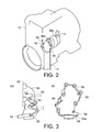
FIG. 2 is a perspective view schematically showing a configuration around an engine of the system for injecting fuel into an exhaust pipe. -
FIG. 3 is a diagram showing an example of an exhaust adaptor, whereinFIG. 3(a) is a side view andFIG. 3(b) is a front view. -
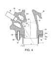
FIG. 4 is a cross-sectional diagram showing a structure of a connection between the exhaust adaptor and the exhaust pipe. - An embodiment for carrying out the present invention is described hereinafter in detail with reference to the drawings.
- First, an exhaust gas purifying system 1 having a
system 5 for injecting fuel into an exhaust pipe according to the present embodiment is described with reference toFIG. 1 . The exhaust gas purifying system 1 has a continuous regeneration-type DPF (or DPD: Diesel Particulate Defuser)device 12 in anexhaust pipe 11 of a diesel engine (simply referred hereinafter as "engine") 10, the continuous regeneration-type DPF device 12 being a type of an exhaust gas purifying device. The continuous regeneration-type DPF device 12 has aDPF 12b for collecting PM contained in exhaust gas and aDOC 12a provided on the upstream side of theDPF 12b. TheDPF 12b is constituted by a CSF (Catalyzed Soot Filter). Asilencer 13 is disposed in theexhaust pipe 11 located in a downstream of the continuous regeneration-type DPF device 12. Exhaust gas G is purified by the continuous regeneration-type DPF device 12 and emitted to the atmosphere via thesilencer 13 as purified exhaust gas Gc. - The
DOC 12a is formed by allowing a carrier having a honeycomb structure of porous ceramic to carry an oxidation catalyst such as platinum. TheDPF 12b is formed from a monolithic honeycomb wall-flow type filter in which an inlet and outlet of a porous ceramic honeycomb channel are sealed alternately. This filter carries a catalyst such as platinum or cerium oxide. The PM (particulate matter) contained in the exhaust gas G is collected (trapped) by a porous ceramic wall. - A conduction pipe that connects the front and rear sides of the
DPF 12b is provided with adifferential pressure sensor 31 for detecting the difference in pressure between the front side and rear side of theDPF 12b in order to estimate the deposition amount of PM on theDPF 12b. Theexhaust pipe 11 located on the downstream side of the continuous regeneration-type DPF device 12 is provided with anexhaust throttle valve 14 as means for throttling the exhaust gas. Theexhaust pipe 11 located on the upstream side of the continuous regeneration-type DPF device 12 is provided with anexhaust brake 20. - A DOC inlet
exhaust temperature sensor 32 for detecting the temperature of the exhaust gas flowing into theDOC 12a is provided on the upstream side of theDOC 12a of the continuous regeneration-type DPF device 12. A DPF inletexhaust temperature sensor 33 for detecting the temperature of the exhaust gas flowing into theDPF 12b is provided between theDOC 12a and theDPF 12b. - An
intake pipe 15 of theengine 10 is provided with, over the length from an intake port to theengine 10, anair cleaner 16, MAF sensor (incoming air volume sensor) 17,compressor 36b of aturbocharger 36, and intake throttle valve (intake throttle) 18. Theintake throttle valve 18 adjusts the intake volume of exhaust gas supplied to an intake manifold 37. The exhaust gas discharged from anexhaust manifold 38 flows into the continuous regeneration-type DPF device 12 through aturbine 36a of theturbocharger 36 and theexhaust brake 20. Theturbocharger 36 is mounted in theengine 10. A front end of theexhaust pipe 11 is connected to a lower end of an after-mentionedexhaust adaptor 50 that forms an outlet-side exhaust path 51 at theturbine 36a. Theexhaust adaptor 50 is provided with afuel injection valve 52 for injecting fuel directly into theexhaust pipe 11. - An EGR
pipe 19, which returns some of the exhaust gas discharged from theengine 10 to the intake manifold 37, is connected to the intake manifold 37 and theexhaust manifold 38. The EGRpipe 19 is provided with anEGR cooler 39 for cooling the exhaust gas returning to the intake manifold 37, and an EGR valve 21 for adjusting an EGR amount, which is the amount of exhaust gas returning to the intake manifold 37. - Signals from the
MAF sensor 17, the DOC inletexhaust temperature sensor 32, the DPF inletexhaust temperature sensor 33, avehicle speed sensor 34, and an engine speed sensor 35 are input to an ECU (electronic control unit) 40 that functions as a control device for controlling theentire engine 10 and performing DPF regeneration control. A control signal sent from theECU 40 controls theexhaust throttle valve 14, theexhaust brake 20, theintake throttle valve 18, the EGR valve 21, afuel injection device 22, thefuel injection valve 52, and the like. - The exhaust gas purifying system 1 has a total post amount computation part, an accumulated diluted amount calculation part, a regeneration interval measuring part, and a forcible regeneration part, which are all mounted in the
ECU 40. - The total post amount computation part computes a total post amount required in a single DPF regeneration. The accumulated diluted amount calculation part integrates a diluted amount for each DPF regeneration and subtracts a diluted amount from the obtained result to calculate the accumulated diluted amount, the diluted amount decreasing as a vehicle travels. The regeneration interval measuring part measures a regeneration interval between the end of a DPF regeneration and the beginning of the subsequent DPF regeneration. The forcible regeneration part performs automatic regeneration where DPF regeneration takes place automatically during traveling of the vehicle, when a condition that the accumulated diluted amount is less than a predetermined threshold value and a condition that the regeneration interval is equal to or greater than a predetermined threshold value (referred to as "automatic regeneration conditions," hereinafter) are satisfied when the PM deposition amount in the
DPF 12b exceeds a predetermined amount. The forcible regeneration part turns on an automatic regeneration lamp (green) 24 during the automatic regeneration. - While the vehicle is stopped, the forcible regeneration part encourages a driver to perform manual regeneration where the DPF regeneration is performed manually, when the automatic regeneration conditions are not satisfied when the PM deposition amount in the
DPF 12b exceeds the predetermined amount. The forcible regeneration part consequently performs the manual regeneration in response to an operation that is input by the driver during the stopped state of the vehicle. When the PM deposition amount in theDPF 12b exceeds the predetermined amount and the automatic regeneration conditions are not satisfied, the forcible regeneration part flashes (blinks) a manual regeneration lamp (orange) 23 to encourage (alert) the driver to perform the manual regeneration. Furthermore, during the manual regeneration, the forcible regeneration part turns on the manual regeneration lamp (orange) 23 to display information indicating that the manual regeneration is performed. In addition, the forcible regeneration part executes the manual regeneration when the driver presses a manual regeneration button (DPF manual regeneration execution switch) 25 during the stopped state of the vehicle. - The PM deposition amount is detected based on the difference in pressure between the front side and rear side of the
DPF 12b, which is detected by thedifferential pressure sensor 31, and a travel distance of the vehicle that is calculated based on the vehicle speed detected by thevehicle speed sensor 34. In other words, when the difference in pressure between the front side and rear side of theDPF 12b exceeds a predetermined threshold value or when the travel distance exceeds a predetermined threshold value, the forcible regeneration part determines that the PM deposition amount in theDPF 12b exceeds the predetermined amount. - In the DPF regeneration, when the exhaust gas temperature that is detected by the DOC inlet
exhaust temperature sensor 32 or the DPF inletexhaust temperature sensor 33 is lower than a first determination value (a DOC activation temperature of, for example, 250°C), multiple injection is performed along with post injection or in-pipe injection, to increase the temperature of the exhaust gas discharged from theengine 10. When the exhaust gas temperature that is detected by the DOC inletexhaust temperature sensor 32 or the DPF inletexhaust temperature sensor 33 is equal to or greater than the first determination value, PM burning removal control is executed to perform post injection or in-pipe injection, forcibly regenerating theDPF 12b. In the PM burning removal control, multiple injection is combined with post injection or in-pipe injection, if needed. In the manual regeneration, theexhaust brake 20 is closed until the exhaust gas temperature becomes equal to or greater than the first determination value, whereby the exhaust gas temperature is increased rapidly. In the manual regeneration, theexhaust throttle valve 14 is closed to throttle the exhaust gas at the time of the PM burning removal control, whereby the exhaust gas temperature is increased. - In the
system 5 for injecting fuel into an exhaust pipe, which has thefuel injection valve 52 provided in theexhaust adaptor 50 of theturbocharger 36 and injects fuel directly into theexhaust pipe 11 in order to perform the DPF regeneration, the front end of theexhaust pipe 11 is connected to the lower end of theexhaust adaptor 50. Therefore, the fuel injected from thefuel injection valve 52 falls on this connection, causing fuel leakage where the fuel oozes out from the connection. In order to solve this problem, the lower end of theexhaust adaptor 50 is provided with alower flange part 54 to which a frontend flange part 53 of theexhaust pipe 11 is connected, as shown inFIGS. 2 to 4 . In addition, atubular shielding part 55 for preventing the fuel from falling ontoflange surfaces end flange part 53 and thelower flange part 54 is provided in the lower end of theexhaust adaptor 50 in such a manner as to protrude to theexhaust pipe 11. This shieldingpart 55 is integrated with the lower end of theexhaust adaptor 50, by allowing the inner wall of theexhaust path 51 of theexhaust adaptor 50 to protrude or extend downward (i.e., to the inside of the exhaust pipe 11). - An outer diameter d of the shielding
part 55 is, for example, 70 mm. A protruding length h of the shieldingpart 55 is, for example, 16.5 mm. A predetermined space (clearance) s for preventing the fuel from oozing by a capillary action is provided between the shieldingpart 55 and theexhaust pipe 11 in a radial direction of theexhaust pipe 11. In other words, the space s is preferably set to have a size enough to prevent the fuel from oozing, by a capillary action. The width of this space s is, for example, 2.7 mm. A smooth, molybdenum-coatedgasket 56 with heat-resistant property is interposed between thelower flange part 54 of theexhaust adaptor 50 and the frontend flange part 53 of theexhaust pipe 11. - A plurality of
stud bolts 57 are implanted in thelower flange part 54 of theexhaust adaptor 50. Screwingnuts 58 to thestud bolts 57 connects the frontend flange part 53 of theexhaust pipe 11 to thelower flange 54. - The
exhaust adaptor 50 is attached with thefuel injection valve 52 that extends at an angle α from a shaft center (shaft center line) c of theexhaust pipe 11 in order to inject the fuel obliquely downward to theexhaust path 51 such that the fuel can easily be mixed into the exhaust gas. Anupper flange part 59 that is connected to theturbine 36a of theturbocharger 36 is provided in an upper part of theexhaust adaptor 50. A vertically intermediate part of theexhaust adaptor 50 is provided with a fuel injectionvalve attachment part 60 to which thefuel injection valve 52 is attached. This fuel injectionvalve attachment part 60 is provided with aninsertion hole 61 into which the front end of thefuel injection valve 52 is inserted. - In order to prevent a fuel content of the exhaust gas from adhering and depositing onto a
spray hole 62 at thefront end 52a of thefuel injection valve 52 inserted into theinsertion hole 61 when thespray hole 62 is exposed to the high-temperature exhaust gas, thefront end 52a of thefuel injection valve 52 is disposed radially outwardly away from an inner wall part of theexhaust path 51 of theexhaust adaptor 50 so as not to come into contact with a flow of the exhaust gas inside theexhaust adaptor 50. More specifically, the inner wall part of theexhaust path 51 of theexhaust adaptor 50 is provided with a cone-shapedconcave part 63 that gradually tapers from theexhaust path 51 toward the front end of theinsertion hole 61. Thefront end 52a of thefuel injection valve 52 is also provided away from (in such a manner as to be retracted from) a boundary where the front end of theinsertion hole 61 and theconcave part 63 intersect with each other. - The
coolant passage 64 for cooling the periphery of thefront end 52a of thefuel injection valve 52 is provided in the fuel injectionvalve attachment part 60. A coolant of theengine 10 circulates in thecoolant passage 64 through acoolant pipe line 65, which is not shown. - According to the
system 5 for injecting fuel into an exhaust path, which is configured as described above, theexhaust pipe 11 is connected to theengine 10 via theexhaust adaptor 50 and fuel is injected directly into theexhaust pipe 11 through thefuel injection valve 52 provided in theexhaust adaptor 50. The lower end of theexhaust adaptor 50 is provided with thelower flange part 54 to which the frontend flange part 53 of theexhaust pipe 11 is connected, and thetubular shielding part 55 for preventing the fuel from falling onto the flange surfaces 53a and 54a of the frontend flange part 53 and thelower flange part 54 is provided in such a manner as to protrude into theexhaust pipe 11. This configuration can prevent the fuel from falling onto the flange surfaces 53a and 54a and leaking from the connection between theexhaust adaptor 50 and theexhaust pipe 11. - Moreover, the predetermined space s, which is provided between the
exhaust pipe 11 and the shieldingpart 55 in the radial direction of theexhaust pipe 11 to prevent the fuel from oozing, can also prevent the fuel leakage. - In addition, because the molybdenum-coated
gasket 56 is interposed between thelower flange part 54 of theexhaust adaptor 50 and the frontend flange part 53 of theexhaust pipe 11, the heat-resistant property and smoothness of the molybdenum coating can ensure sealing properties while tolerating vibration-induced slippage between the flange surfaces 53a and 54a of the frontend flange part 53 and thelower flange part 54 that face each other. - Unlike the post injection, dilution does not occur in the direct in-pipe injection. Thus, by not adding up the diluted amounts in the exhaust gas purifying system 1, the manual generation is less requested, improving user convenience.
-
- 5
- System for injecting fuel into exhaust pipe
- 10
- Diesel engine
- 11
- Exhaust pipe
- 12
- Continuous regeneration-type DPF device
- 12a
- DOC
- 12b
- DPF
- 36
- Turbocharger
- 50
- Exhaust adaptor
- 52
- Fuel injection valve
- 53
- Front end flange part
- 54
- Lower flange part
- 53a, 54a
- Flange surface
- 55
- Shielding part
- 56
- Gasket
- s
- Predetermined space
Claims (5)
- A system for injecting fuel into an exhaust pipe, in which the exhaust pipe is connected to an engine via an exhaust adaptor and fuel is injected directly into the exhaust pipe through a fuel injection valve provided in the exhaust adaptor,
wherein a lower end of the exhaust adaptor is provided with a lower flange part to which a front end flange part of the exhaust pipe is connected, and a tubular shielding part for preventing the fuel from falling onto flange surfaces of the front end flange part and the lower flange part is provided in such a manner as to protrude into the exhaust pipe. - The system for injecting fuel into an exhaust pipe according to claim 1, wherein a predetermined space for preventing the fuel from oozing is provided between the exhaust pipe and the shielding part in a radial direction of the exhaust pipe.
- The system for injecting fuel into an exhaust pipe according to claim 1 or 2, wherein a molybdenum-coated gasket is interposed between the lower flange part of the exhaust adaptor and the front end flange part of the exhaust pipe.
- The system for injecting fuel into an exhaust pipe according to any one of claims 1 to 3, wherein the shielding part is integrated with the lower end of the exhaust adaptor, by allowing an inner wall of an exhaust path of the exhaust adaptor to extend into the exhaust pipe.
- The system for injecting fuel into an exhaust pipe according to claim 2, wherein the space is provided between the exhaust pipe and the shielding part and is set to have a size enough to prevent the fuel from oozing by a capillary action.
Applications Claiming Priority (2)
| Application Number | Priority Date | Filing Date | Title |
|---|---|---|---|
| JP2010134520A JP5768331B2 (en) | 2010-06-11 | 2010-06-11 | Exhaust pipe fuel injection system |
| PCT/JP2011/063327 WO2011155592A1 (en) | 2010-06-11 | 2011-06-10 | Intra-exhaust-pipe fuel-injection system |
Publications (3)
| Publication Number | Publication Date |
|---|---|
| EP2581574A1 true EP2581574A1 (en) | 2013-04-17 |
| EP2581574A4 EP2581574A4 (en) | 2017-03-08 |
| EP2581574B1 EP2581574B1 (en) | 2019-04-24 |
Family
ID=45098195
Family Applications (1)
| Application Number | Title | Priority Date | Filing Date |
|---|---|---|---|
| EP11792549.5A Not-in-force EP2581574B1 (en) | 2010-06-11 | 2011-06-10 | Intra-exhaust-pipe fuel-injection system |
Country Status (5)
| Country | Link |
|---|---|
| US (1) | US9790829B2 (en) |
| EP (1) | EP2581574B1 (en) |
| JP (1) | JP5768331B2 (en) |
| CN (1) | CN102933806B (en) |
| WO (1) | WO2011155592A1 (en) |
Families Citing this family (9)
| Publication number | Priority date | Publication date | Assignee | Title |
|---|---|---|---|---|
| JP2015010478A (en) * | 2013-06-26 | 2015-01-19 | ヤンマー株式会社 | Agricultural work vehicle |
| JP2015010477A (en) * | 2013-06-26 | 2015-01-19 | ヤンマー株式会社 | Agricultural work vehicle |
| JP6766555B2 (en) * | 2016-09-27 | 2020-10-14 | いすゞ自動車株式会社 | In-exhaust injection device |
| CN107131058B (en) * | 2017-05-12 | 2023-08-01 | 广西玉柴机器股份有限公司 | Connection structure of exhaust butterfly valve |
| US10876450B2 (en) * | 2019-05-22 | 2020-12-29 | FEV Europe GmbH | Splitflow catalyst system |
| US11808192B2 (en) | 2019-08-14 | 2023-11-07 | Cummins Emission Solutions Inc. | Exhaust gas aftertreatment system |
| SE543851C2 (en) * | 2019-12-12 | 2021-08-10 | Scania Cv Ab | Exhaust additive dosing system comprising a turbocharger |
| GB202203717D0 (en) * | 2022-03-17 | 2022-05-04 | Cummins Ltd | Turbine dosing system for dosing into regions of desirable flow properties |
| GB202203712D0 (en) * | 2022-03-17 | 2022-05-04 | Cummins Ltd | Turbine dosing system |
Family Cites Families (32)
| Publication number | Priority date | Publication date | Assignee | Title |
|---|---|---|---|---|
| DE2423507A1 (en) * | 1974-05-15 | 1975-11-27 | Audi Nsu Auto Union Ag | COMBUSTION MACHINE WITH AT LEAST ONE EXHAUST DUCT |
| JPS53101962U (en) * | 1977-01-24 | 1978-08-17 | ||
| JPH0621555B2 (en) * | 1989-02-27 | 1994-03-23 | 神鋼電機株式会社 | Ammonia mixing device in denitration device |
| JPH0377019U (en) * | 1989-11-29 | 1991-08-01 | ||
| DE4436397B4 (en) | 1994-10-12 | 2006-06-08 | Robert Bosch Gmbh | Device for aftertreatment of exhaust gases |
| JPH08144753A (en) * | 1994-11-17 | 1996-06-04 | Mazda Motor Corp | Exhaust pipe connection structure |
| JPH08232759A (en) * | 1995-02-22 | 1996-09-10 | Nippon Gasket Co Ltd | Metallic gasket for exhaust manifold |
| DE19806265C5 (en) | 1998-02-16 | 2004-07-22 | Siemens Ag | dosing |
| DE19856366C1 (en) | 1998-12-07 | 2000-04-20 | Siemens Ag | Urea injection system treating exhaust gases from lean burn engine, comprises air-cooling jacket surrounding injector valve to keep it cool, so that a petrol injection valve may be used |
| DE19919426C1 (en) * | 1999-04-28 | 2000-03-30 | Siemens Ag | Valve mounting for dosing valve of IC engine exhaust gas catalyser |
| SE516624C2 (en) * | 2000-06-14 | 2002-02-05 | Volvo Lastvagnar Ab | Apparatus for injecting urea into a turbine housing in an exhaust system |
| JP4327445B2 (en) * | 2002-12-18 | 2009-09-09 | 日野自動車株式会社 | Exhaust purification equipment |
| JP2005264756A (en) * | 2004-03-16 | 2005-09-29 | Toyota Industries Corp | Exhaust emission control device |
| JP2006329019A (en) * | 2005-05-25 | 2006-12-07 | Hino Motors Ltd | Diesel engine exhaust pipe |
| JP4677837B2 (en) | 2005-07-08 | 2011-04-27 | いすゞ自動車株式会社 | Exhaust gas purification system regeneration control method and exhaust gas purification system |
| JP2007071161A (en) | 2005-09-08 | 2007-03-22 | Toyota Motor Corp | Exhaust gas purification device for internal combustion engine |
| JP4404048B2 (en) | 2005-12-28 | 2010-01-27 | トヨタ自動車株式会社 | Exhaust gas purification device for internal combustion engine |
| JP2007321647A (en) * | 2006-05-31 | 2007-12-13 | Hitachi Ltd | Exhaust treatment equipment for engines |
| DE102006058402A1 (en) * | 2006-12-12 | 2008-06-19 | Bayerische Motoren Werke Ag | Device for admixing a reducing agent in an exhaust gas stream of an internal combustion engine |
| JP4779959B2 (en) * | 2006-12-20 | 2011-09-28 | 株式会社デンソー | Exhaust purification device |
| JP2009156068A (en) * | 2007-12-25 | 2009-07-16 | Mitsubishi Motors Corp | Exhaust gas purification device for internal combustion engine |
| JP4407843B2 (en) * | 2007-12-25 | 2010-02-03 | 三菱自動車工業株式会社 | Exhaust gas purification device for internal combustion engine |
| JP4332756B2 (en) * | 2007-12-25 | 2009-09-16 | 三菱自動車工業株式会社 | Exhaust gas purification device for internal combustion engine |
| JP4816967B2 (en) * | 2007-12-25 | 2011-11-16 | 三菱自動車工業株式会社 | Exhaust gas purification device for internal combustion engine |
| JP2009167965A (en) | 2008-01-18 | 2009-07-30 | Mitsubishi Motors Corp | Exhaust purification device |
| DE102008031887A1 (en) * | 2008-07-08 | 2010-03-04 | J. Eberspächer GmbH & Co. KG | exhaust system |
| JP4924844B2 (en) | 2008-07-29 | 2012-04-25 | 三菱自動車工業株式会社 | Exhaust purification device |
| EP2180156A1 (en) | 2008-10-24 | 2010-04-28 | Magneti Marelli Powertrain S.p.A. | Injection system for injecting a reducing substance into an exhaust system of an internal combustion engine |
| US20110079003A1 (en) * | 2009-10-05 | 2011-04-07 | Caterpillar Inc. | Reductant nozzle indentation mount |
| US8240137B2 (en) * | 2009-10-27 | 2012-08-14 | Cummins Filtration Ip, Inc. | Reductant injection and decomposition system |
| US8549842B2 (en) | 2009-12-01 | 2013-10-08 | GM Global Technology Operations LLC | Air assisted injector, and injection system and exhaust treatment system incorporating the same |
| US8438839B2 (en) * | 2010-10-19 | 2013-05-14 | Tenneco Automotive Operating Company Inc. | Exhaust gas stream vortex breaker |
-
2010
- 2010-06-11 JP JP2010134520A patent/JP5768331B2/en active Active
-
2011
- 2011-06-10 WO PCT/JP2011/063327 patent/WO2011155592A1/en not_active Ceased
- 2011-06-10 CN CN201180028609.4A patent/CN102933806B/en active Active
- 2011-06-10 EP EP11792549.5A patent/EP2581574B1/en not_active Not-in-force
- 2011-06-10 US US13/703,438 patent/US9790829B2/en active Active
Non-Patent Citations (1)
| Title |
|---|
| See references of WO2011155592A1 * |
Also Published As
| Publication number | Publication date |
|---|---|
| WO2011155592A1 (en) | 2011-12-15 |
| CN102933806B (en) | 2016-03-30 |
| US20130086885A1 (en) | 2013-04-11 |
| JP2011256852A (en) | 2011-12-22 |
| JP5768331B2 (en) | 2015-08-26 |
| EP2581574A4 (en) | 2017-03-08 |
| EP2581574B1 (en) | 2019-04-24 |
| US9790829B2 (en) | 2017-10-17 |
| CN102933806A (en) | 2013-02-13 |
Similar Documents
| Publication | Publication Date | Title |
|---|---|---|
| EP2581574B1 (en) | Intra-exhaust-pipe fuel-injection system | |
| US8316637B2 (en) | Exhaust emission purification method and exhaust emission purification system | |
| US20090025372A1 (en) | Method for Controlling Exhaust Gas Purification System and Exhaust Gas Purification System | |
| US9086000B2 (en) | Diesel particulate filter system | |
| EP2581573B1 (en) | System for injecting fuel into exhaust pipe | |
| EP2581571B1 (en) | Exhaust gas purification system | |
| US8961668B2 (en) | Exhaust gas purification system | |
| US8549843B2 (en) | Method of controlling exhaust gas purification system and exhaust gas purification system | |
| EP2685072A1 (en) | Control device for internal combustion engine | |
| EP2581569B1 (en) | Dpf system | |
| EP2581572B1 (en) | Exhaust-gas purification system | |
| EP3093482B1 (en) | Exhaust gas purification system of internal combustion engine and exhaust gas purification method of internal combustion engine | |
| JP2012102684A (en) | Exhaust emission control device for engine | |
| JP2014109228A (en) | Nozzle clogging detector | |
| JP4052268B2 (en) | Exhaust gas purification device for internal combustion engine | |
| JP2012127287A (en) | Exhaust pipe injector of engine | |
| JP2008223557A (en) | Introduction pipe connection structure and exhaust gas purification system | |
| JP2011247129A (en) | Exhaust emission control system | |
| JP5573817B2 (en) | Exhaust gas purification device for internal combustion engine | |
| JP2008261301A (en) | Exhaust gas purification method and exhaust gas purification system |
Legal Events
| Date | Code | Title | Description |
|---|---|---|---|
| PUAI | Public reference made under article 153(3) epc to a published international application that has entered the european phase |
Free format text: ORIGINAL CODE: 0009012 |
|
| 17P | Request for examination filed |
Effective date: 20130110 |
|
| AK | Designated contracting states |
Kind code of ref document: A1 Designated state(s): AL AT BE BG CH CY CZ DE DK EE ES FI FR GB GR HR HU IE IS IT LI LT LU LV MC MK MT NL NO PL PT RO RS SE SI SK SM TR |
|
| DAX | Request for extension of the european patent (deleted) | ||
| REG | Reference to a national code |
Ref country code: DE Ref legal event code: R079 Ref document number: 602011058343 Country of ref document: DE Free format text: PREVIOUS MAIN CLASS: F01N0003020000 Ipc: F01N0013080000 |
|
| RA4 | Supplementary search report drawn up and despatched (corrected) |
Effective date: 20170202 |
|
| RIC1 | Information provided on ipc code assigned before grant |
Ipc: F01N 3/36 20060101ALI20170127BHEP Ipc: B01D 53/94 20060101ALI20170127BHEP Ipc: F01N 3/025 20060101ALI20170127BHEP Ipc: F01N 13/18 20100101ALI20170127BHEP Ipc: F01N 13/08 20100101AFI20170127BHEP |
|
| STAA | Information on the status of an ep patent application or granted ep patent |
Free format text: STATUS: EXAMINATION IS IN PROGRESS |
|
| 17Q | First examination report despatched |
Effective date: 20180313 |
|
| GRAP | Despatch of communication of intention to grant a patent |
Free format text: ORIGINAL CODE: EPIDOSNIGR1 |
|
| STAA | Information on the status of an ep patent application or granted ep patent |
Free format text: STATUS: GRANT OF PATENT IS INTENDED |
|
| INTG | Intention to grant announced |
Effective date: 20181106 |
|
| GRAS | Grant fee paid |
Free format text: ORIGINAL CODE: EPIDOSNIGR3 |
|
| GRAA | (expected) grant |
Free format text: ORIGINAL CODE: 0009210 |
|
| STAA | Information on the status of an ep patent application or granted ep patent |
Free format text: STATUS: THE PATENT HAS BEEN GRANTED |
|
| AK | Designated contracting states |
Kind code of ref document: B1 Designated state(s): AL AT BE BG CH CY CZ DE DK EE ES FI FR GB GR HR HU IE IS IT LI LT LU LV MC MK MT NL NO PL PT RO RS SE SI SK SM TR |
|
| REG | Reference to a national code |
Ref country code: GB Ref legal event code: FG4D |
|
| REG | Reference to a national code |
Ref country code: CH Ref legal event code: EP |
|
| REG | Reference to a national code |
Ref country code: AT Ref legal event code: REF Ref document number: 1124431 Country of ref document: AT Kind code of ref document: T Effective date: 20190515 Ref country code: IE Ref legal event code: FG4D |
|
| REG | Reference to a national code |
Ref country code: DE Ref legal event code: R096 Ref document number: 602011058343 Country of ref document: DE |
|
| REG | Reference to a national code |
Ref country code: NL Ref legal event code: MP Effective date: 20190424 |
|
| PGFP | Annual fee paid to national office [announced via postgrant information from national office to epo] |
Ref country code: FR Payment date: 20190625 Year of fee payment: 9 |
|
| REG | Reference to a national code |
Ref country code: LT Ref legal event code: MG4D |
|
| PG25 | Lapsed in a contracting state [announced via postgrant information from national office to epo] |
Ref country code: NL Free format text: LAPSE BECAUSE OF FAILURE TO SUBMIT A TRANSLATION OF THE DESCRIPTION OR TO PAY THE FEE WITHIN THE PRESCRIBED TIME-LIMIT Effective date: 20190424 |
|
| PG25 | Lapsed in a contracting state [announced via postgrant information from national office to epo] |
Ref country code: FI Free format text: LAPSE BECAUSE OF FAILURE TO SUBMIT A TRANSLATION OF THE DESCRIPTION OR TO PAY THE FEE WITHIN THE PRESCRIBED TIME-LIMIT Effective date: 20190424 Ref country code: PT Free format text: LAPSE BECAUSE OF FAILURE TO SUBMIT A TRANSLATION OF THE DESCRIPTION OR TO PAY THE FEE WITHIN THE PRESCRIBED TIME-LIMIT Effective date: 20190824 Ref country code: NO Free format text: LAPSE BECAUSE OF FAILURE TO SUBMIT A TRANSLATION OF THE DESCRIPTION OR TO PAY THE FEE WITHIN THE PRESCRIBED TIME-LIMIT Effective date: 20190724 Ref country code: SE Free format text: LAPSE BECAUSE OF FAILURE TO SUBMIT A TRANSLATION OF THE DESCRIPTION OR TO PAY THE FEE WITHIN THE PRESCRIBED TIME-LIMIT Effective date: 20190424 Ref country code: AL Free format text: LAPSE BECAUSE OF FAILURE TO SUBMIT A TRANSLATION OF THE DESCRIPTION OR TO PAY THE FEE WITHIN THE PRESCRIBED TIME-LIMIT Effective date: 20190424 Ref country code: LT Free format text: LAPSE BECAUSE OF FAILURE TO SUBMIT A TRANSLATION OF THE DESCRIPTION OR TO PAY THE FEE WITHIN THE PRESCRIBED TIME-LIMIT Effective date: 20190424 Ref country code: HR Free format text: LAPSE BECAUSE OF FAILURE TO SUBMIT A TRANSLATION OF THE DESCRIPTION OR TO PAY THE FEE WITHIN THE PRESCRIBED TIME-LIMIT Effective date: 20190424 Ref country code: ES Free format text: LAPSE BECAUSE OF FAILURE TO SUBMIT A TRANSLATION OF THE DESCRIPTION OR TO PAY THE FEE WITHIN THE PRESCRIBED TIME-LIMIT Effective date: 20190424 |
|
| PGFP | Annual fee paid to national office [announced via postgrant information from national office to epo] |
Ref country code: GB Payment date: 20190624 Year of fee payment: 9 Ref country code: DE Payment date: 20190725 Year of fee payment: 9 |
|
| PG25 | Lapsed in a contracting state [announced via postgrant information from national office to epo] |
Ref country code: LV Free format text: LAPSE BECAUSE OF FAILURE TO SUBMIT A TRANSLATION OF THE DESCRIPTION OR TO PAY THE FEE WITHIN THE PRESCRIBED TIME-LIMIT Effective date: 20190424 Ref country code: RS Free format text: LAPSE BECAUSE OF FAILURE TO SUBMIT A TRANSLATION OF THE DESCRIPTION OR TO PAY THE FEE WITHIN THE PRESCRIBED TIME-LIMIT Effective date: 20190424 Ref country code: BG Free format text: LAPSE BECAUSE OF FAILURE TO SUBMIT A TRANSLATION OF THE DESCRIPTION OR TO PAY THE FEE WITHIN THE PRESCRIBED TIME-LIMIT Effective date: 20190724 Ref country code: GR Free format text: LAPSE BECAUSE OF FAILURE TO SUBMIT A TRANSLATION OF THE DESCRIPTION OR TO PAY THE FEE WITHIN THE PRESCRIBED TIME-LIMIT Effective date: 20190725 Ref country code: PL Free format text: LAPSE BECAUSE OF FAILURE TO SUBMIT A TRANSLATION OF THE DESCRIPTION OR TO PAY THE FEE WITHIN THE PRESCRIBED TIME-LIMIT Effective date: 20190424 |
|
| REG | Reference to a national code |
Ref country code: AT Ref legal event code: MK05 Ref document number: 1124431 Country of ref document: AT Kind code of ref document: T Effective date: 20190424 |
|
| PG25 | Lapsed in a contracting state [announced via postgrant information from national office to epo] |
Ref country code: IS Free format text: LAPSE BECAUSE OF FAILURE TO SUBMIT A TRANSLATION OF THE DESCRIPTION OR TO PAY THE FEE WITHIN THE PRESCRIBED TIME-LIMIT Effective date: 20190824 |
|
| REG | Reference to a national code |
Ref country code: DE Ref legal event code: R097 Ref document number: 602011058343 Country of ref document: DE |
|
| PG25 | Lapsed in a contracting state [announced via postgrant information from national office to epo] |
Ref country code: MC Free format text: LAPSE BECAUSE OF FAILURE TO SUBMIT A TRANSLATION OF THE DESCRIPTION OR TO PAY THE FEE WITHIN THE PRESCRIBED TIME-LIMIT Effective date: 20190424 Ref country code: AT Free format text: LAPSE BECAUSE OF FAILURE TO SUBMIT A TRANSLATION OF THE DESCRIPTION OR TO PAY THE FEE WITHIN THE PRESCRIBED TIME-LIMIT Effective date: 20190424 Ref country code: DK Free format text: LAPSE BECAUSE OF FAILURE TO SUBMIT A TRANSLATION OF THE DESCRIPTION OR TO PAY THE FEE WITHIN THE PRESCRIBED TIME-LIMIT Effective date: 20190424 Ref country code: EE Free format text: LAPSE BECAUSE OF FAILURE TO SUBMIT A TRANSLATION OF THE DESCRIPTION OR TO PAY THE FEE WITHIN THE PRESCRIBED TIME-LIMIT Effective date: 20190424 Ref country code: SK Free format text: LAPSE BECAUSE OF FAILURE TO SUBMIT A TRANSLATION OF THE DESCRIPTION OR TO PAY THE FEE WITHIN THE PRESCRIBED TIME-LIMIT Effective date: 20190424 Ref country code: RO Free format text: LAPSE BECAUSE OF FAILURE TO SUBMIT A TRANSLATION OF THE DESCRIPTION OR TO PAY THE FEE WITHIN THE PRESCRIBED TIME-LIMIT Effective date: 20190424 Ref country code: CZ Free format text: LAPSE BECAUSE OF FAILURE TO SUBMIT A TRANSLATION OF THE DESCRIPTION OR TO PAY THE FEE WITHIN THE PRESCRIBED TIME-LIMIT Effective date: 20190424 |
|
| REG | Reference to a national code |
Ref country code: CH Ref legal event code: PL |
|
| PG25 | Lapsed in a contracting state [announced via postgrant information from national office to epo] |
Ref country code: IT Free format text: LAPSE BECAUSE OF FAILURE TO SUBMIT A TRANSLATION OF THE DESCRIPTION OR TO PAY THE FEE WITHIN THE PRESCRIBED TIME-LIMIT Effective date: 20190424 Ref country code: SM Free format text: LAPSE BECAUSE OF FAILURE TO SUBMIT A TRANSLATION OF THE DESCRIPTION OR TO PAY THE FEE WITHIN THE PRESCRIBED TIME-LIMIT Effective date: 20190424 |
|
| PLBE | No opposition filed within time limit |
Free format text: ORIGINAL CODE: 0009261 |
|
| STAA | Information on the status of an ep patent application or granted ep patent |
Free format text: STATUS: NO OPPOSITION FILED WITHIN TIME LIMIT |
|
| REG | Reference to a national code |
Ref country code: BE Ref legal event code: MM Effective date: 20190630 |
|
| PG25 | Lapsed in a contracting state [announced via postgrant information from national office to epo] |
Ref country code: TR Free format text: LAPSE BECAUSE OF FAILURE TO SUBMIT A TRANSLATION OF THE DESCRIPTION OR TO PAY THE FEE WITHIN THE PRESCRIBED TIME-LIMIT Effective date: 20190424 |
|
| 26N | No opposition filed |
Effective date: 20200127 |
|
| PG25 | Lapsed in a contracting state [announced via postgrant information from national office to epo] |
Ref country code: IE Free format text: LAPSE BECAUSE OF NON-PAYMENT OF DUE FEES Effective date: 20190610 |
|
| PG25 | Lapsed in a contracting state [announced via postgrant information from national office to epo] |
Ref country code: SI Free format text: LAPSE BECAUSE OF FAILURE TO SUBMIT A TRANSLATION OF THE DESCRIPTION OR TO PAY THE FEE WITHIN THE PRESCRIBED TIME-LIMIT Effective date: 20190424 Ref country code: BE Free format text: LAPSE BECAUSE OF NON-PAYMENT OF DUE FEES Effective date: 20190630 Ref country code: CH Free format text: LAPSE BECAUSE OF NON-PAYMENT OF DUE FEES Effective date: 20190630 Ref country code: LI Free format text: LAPSE BECAUSE OF NON-PAYMENT OF DUE FEES Effective date: 20190630 Ref country code: LU Free format text: LAPSE BECAUSE OF NON-PAYMENT OF DUE FEES Effective date: 20190610 |
|
| REG | Reference to a national code |
Ref country code: DE Ref legal event code: R119 Ref document number: 602011058343 Country of ref document: DE |
|
| GBPC | Gb: european patent ceased through non-payment of renewal fee |
Effective date: 20200610 |
|
| PG25 | Lapsed in a contracting state [announced via postgrant information from national office to epo] |
Ref country code: GB Free format text: LAPSE BECAUSE OF NON-PAYMENT OF DUE FEES Effective date: 20200610 Ref country code: FR Free format text: LAPSE BECAUSE OF NON-PAYMENT OF DUE FEES Effective date: 20200630 |
|
| PG25 | Lapsed in a contracting state [announced via postgrant information from national office to epo] |
Ref country code: CY Free format text: LAPSE BECAUSE OF FAILURE TO SUBMIT A TRANSLATION OF THE DESCRIPTION OR TO PAY THE FEE WITHIN THE PRESCRIBED TIME-LIMIT Effective date: 20190424 Ref country code: DE Free format text: LAPSE BECAUSE OF NON-PAYMENT OF DUE FEES Effective date: 20210101 |
|
| PG25 | Lapsed in a contracting state [announced via postgrant information from national office to epo] |
Ref country code: MT Free format text: LAPSE BECAUSE OF FAILURE TO SUBMIT A TRANSLATION OF THE DESCRIPTION OR TO PAY THE FEE WITHIN THE PRESCRIBED TIME-LIMIT Effective date: 20190424 Ref country code: HU Free format text: LAPSE BECAUSE OF FAILURE TO SUBMIT A TRANSLATION OF THE DESCRIPTION OR TO PAY THE FEE WITHIN THE PRESCRIBED TIME-LIMIT; INVALID AB INITIO Effective date: 20110610 |
|
| PG25 | Lapsed in a contracting state [announced via postgrant information from national office to epo] |
Ref country code: MK Free format text: LAPSE BECAUSE OF FAILURE TO SUBMIT A TRANSLATION OF THE DESCRIPTION OR TO PAY THE FEE WITHIN THE PRESCRIBED TIME-LIMIT Effective date: 20190424 |