EP2581559A2 - Ensemble adaptateur pour accouplement d'aubes de turbine au disque rotor - Google Patents
Ensemble adaptateur pour accouplement d'aubes de turbine au disque rotor Download PDFInfo
- Publication number
- EP2581559A2 EP2581559A2 EP12179574.4A EP12179574A EP2581559A2 EP 2581559 A2 EP2581559 A2 EP 2581559A2 EP 12179574 A EP12179574 A EP 12179574A EP 2581559 A2 EP2581559 A2 EP 2581559A2
- Authority
- EP
- European Patent Office
- Prior art keywords
- root
- adaptor
- blade
- turbine
- slot
- Prior art date
- Legal status (The legal status is an assumption and is not a legal conclusion. Google has not performed a legal analysis and makes no representation as to the accuracy of the status listed.)
- Granted
Links
- 230000008878 coupling Effects 0.000 title claims abstract description 11
- 238000010168 coupling process Methods 0.000 title claims abstract description 11
- 238000005859 coupling reaction Methods 0.000 title claims abstract description 11
- 239000011153 ceramic matrix composite Substances 0.000 claims description 6
- 239000000919 ceramic Substances 0.000 claims description 5
- 241000725175 Caladium bicolor Species 0.000 claims description 4
- 241000879887 Cyrtopleura costata Species 0.000 claims description 4
- 235000015966 Pleurocybella porrigens Nutrition 0.000 claims description 4
- 229910001092 metal group alloy Inorganic materials 0.000 claims 5
- 239000007789 gas Substances 0.000 description 21
- 238000007789 sealing Methods 0.000 description 5
- 229910010293 ceramic material Inorganic materials 0.000 description 4
- 238000002485 combustion reaction Methods 0.000 description 4
- 239000000463 material Substances 0.000 description 4
- 238000010276 construction Methods 0.000 description 3
- 239000002184 metal Substances 0.000 description 3
- 230000000712 assembly Effects 0.000 description 2
- 238000000429 assembly Methods 0.000 description 2
- 238000010586 diagram Methods 0.000 description 2
- 238000012986 modification Methods 0.000 description 2
- 230000004048 modification Effects 0.000 description 2
- 230000007704 transition Effects 0.000 description 2
- 230000005611 electricity Effects 0.000 description 1
- 230000037406 food intake Effects 0.000 description 1
- 239000000446 fuel Substances 0.000 description 1
- 230000014759 maintenance of location Effects 0.000 description 1
- 238000000034 method Methods 0.000 description 1
Images


Classifications
-
- F—MECHANICAL ENGINEERING; LIGHTING; HEATING; WEAPONS; BLASTING
- F01—MACHINES OR ENGINES IN GENERAL; ENGINE PLANTS IN GENERAL; STEAM ENGINES
- F01D—NON-POSITIVE DISPLACEMENT MACHINES OR ENGINES, e.g. STEAM TURBINES
- F01D5/00—Blades; Blade-carrying members; Heating, heat-insulating, cooling or antivibration means on the blades or the members
- F01D5/30—Fixing blades to rotors; Blade roots ; Blade spacers
- F01D5/3007—Fixing blades to rotors; Blade roots ; Blade spacers of axial insertion type
-
- F—MECHANICAL ENGINEERING; LIGHTING; HEATING; WEAPONS; BLASTING
- F01—MACHINES OR ENGINES IN GENERAL; ENGINE PLANTS IN GENERAL; STEAM ENGINES
- F01D—NON-POSITIVE DISPLACEMENT MACHINES OR ENGINES, e.g. STEAM TURBINES
- F01D5/00—Blades; Blade-carrying members; Heating, heat-insulating, cooling or antivibration means on the blades or the members
- F01D5/12—Blades
- F01D5/14—Form or construction
- F01D5/147—Construction, i.e. structural features, e.g. of weight-saving hollow blades
-
- F—MECHANICAL ENGINEERING; LIGHTING; HEATING; WEAPONS; BLASTING
- F01—MACHINES OR ENGINES IN GENERAL; ENGINE PLANTS IN GENERAL; STEAM ENGINES
- F01D—NON-POSITIVE DISPLACEMENT MACHINES OR ENGINES, e.g. STEAM TURBINES
- F01D5/00—Blades; Blade-carrying members; Heating, heat-insulating, cooling or antivibration means on the blades or the members
- F01D5/30—Fixing blades to rotors; Blade roots ; Blade spacers
- F01D5/3084—Fixing blades to rotors; Blade roots ; Blade spacers the blades being made of ceramics
-
- F—MECHANICAL ENGINEERING; LIGHTING; HEATING; WEAPONS; BLASTING
- F05—INDEXING SCHEMES RELATING TO ENGINES OR PUMPS IN VARIOUS SUBCLASSES OF CLASSES F01-F04
- F05D—INDEXING SCHEME FOR ASPECTS RELATING TO NON-POSITIVE-DISPLACEMENT MACHINES OR ENGINES, GAS-TURBINES OR JET-PROPULSION PLANTS
- F05D2300/00—Materials; Properties thereof
- F05D2300/60—Properties or characteristics given to material by treatment or manufacturing
- F05D2300/603—Composites; e.g. fibre-reinforced
- F05D2300/6033—Ceramic matrix composites [CMC]
Definitions
- the present subject matter relates generally to gas turbines and, more particularly, to an adaptor assembly for coupling turbine blades to rotor disks.
- Turbine stages are typically disposed along the hot gas path such that the hot gases of combustion flow from the transition piece through first-stage nozzles and buckets and through the nozzles and buckets of follow-on turbine stages.
- Each turbine bucket generally includes an airfoil extending radially outwardly from a substantially planar platform and a blade root extending radially inwardly from the platform.
- each turbine bucket is generally configured to be received within one of a plurality of circumferentially spaced root slots defined in one of the rotor disks of the turbine rotor, with each rotor disk being mounted to the rotor shaft for rotation therewith.
- turbine buckets To improve the overall efficiency of a gas turbine, higher operating temperatures are continuously sought. However, as operating temperatures increase, the high temperature durability of the turbine components must correspondingly increase. Thus, efforts have been made to replace the use of metal in the construction of turbine buckets with the use of ceramic materials, such as ceramic matrix composite materials. As a result, many turbine buckets have been redesigned to accommodate the use of ceramic materials, such as by reshaping the blade root. For example, turbine buckets may now include dovetail-shaped roots as opposed to the fir tree-shaped roots used in metallic buckets. Unfortunately, such reshaping can lead to problems in attaching the blade root to pre-existing rotor disks installed within a gas turbine.
- attachment assemblies have been proposed for coupling turbine buckets to rotor disks.
- such assemblies have not provided an effective means for axially retaining and/or sealing the turbine bucket within the assembly.
- an adaptor assembly for coupling a turbine bucket or blade to a rotor disk that provides for effective axial retention and/or sealing of the turbine blade within the assembly would be desirable.
- the present invention resides in an adaptor assembly for coupling a blade root of a turbine blade to a root slot of a rotor disk.
- the adaptor assembly includes a turbine blade having a blade root and an adaptor body having an adaptor root.
- the adaptor body defines a slot having an open end configured to receive the blade root of the turbine blade such that the adaptor root of the adaptor body and the blade root of the turbine blade are adjacent to one another when the blade root of the turbine blade is positioned within the slot. Both the adaptor root of the adaptor body and the blade root of the turbine blade are configured to be received within the root slot of the rotor disk.
- the present invention resides in a gas turbine rotor system.
- the gas turbine rotor system includes a rotor disk having a root slot, a turbine blade having a blade root, and the adaptor assembly as described above.
- the present subject matter discloses an adaptor assembly for coupling a turbine blade (e.g., a turbine bucket) to a rotor disk of the turbine rotor.
- the adaptor assembly may generally include an adaptor body having an adaptor root configured to be coupled to the rotor disk and an adaptor slot configured to axially receive a blade root of the turbine blade. Both the adaptor root of the adaptor body and the blade root of the turbine blade are configured to be received within the root slot of the rotor disk.
- the adaptor assembly may be used in retrofit applications to allow newly designed turbine blades to be coupled to pre-existing rotor disks.
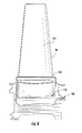
- FIG. 1 illustrates a schematic diagram of a gas turbine 10.
- the gas turbine 10 generally includes a compressor section 12, a plurality of combustors (not shown) disposed within a combustor section 14, and a turbine section 16. Additionally, the system 10 may include a shaft 18 coupled between the compressor section 12 and the turbine section 16.
- the turbine section 16 may generally include a turbine rotor 20 having a plurality of rotor disks 22 (one of which is shown) and a plurality of turbine blades 24 extending radially outwardly from and being coupled to each rotor disk 22 for rotation therewith. Each rotor disk 22 may, in turn, be coupled to a portion of the shaft 18 extending through the turbine section 16.
- the compressor section 12 supplies compressed air to the combustors of the combustor section 14. Air and fuel are mixed and burned within each combustor and hot gases of combustion flow in a hot gas path from the combustor section 14 to the turbine section 16, wherein energy is extracted from the hot gases by the turbine blades 24.
- the energy extracted by the turbine blades 24 is used to rotate to the rotor disks 22 which may, in turn, rotate the shaft 18. The mechanical rotational energy may then be used to power the compressor section 12 and generate electricity.
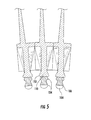
- FIGS 2-4 there are illustrated various views of one embodiment of an adaptor assembly 100 for coupling turbine blades 24 to one of the rotor disks 22 of the turbine rotor 20 in accordance with aspects of the present subject matter.
- FIG. 2 illustrates a perspective view of the adaptor assembly 100 coupled between the turbine blade 24 and the rotor disk 22.
- FIG. 3 illustrates an exploded view of the adaptor assembly 100 and turbine blade 24 shown in FIG. 2 .
- FIG. 4 illustrates a partial, side view of the adaptor assembly 100 and the turbine blade 24 shown in FIG. 2 , particularly illustrating the turbine blade 24 coupled within the adaptor assembly 100.
- the disclosed adaptor assembly 100 may generally comprise an attachment piece for coupling turbine blades 24 to one of the rotor disks 22 (only a portion of which is shown in FIG. 2 ) of the turbine rotor 20.
- the adaptor assembly 100 may be configured to allow turbine blades 24 having one attachment configuration to be coupled to rotor disks 22 having a different attachment configuration.
- the adaptor assembly 100 may include an adaptor body 102 having attachment features generally corresponding to the attachment features of the turbine blade 24 and the rotor disk 22.
- the adaptor body 102 may include an adaptor root 104 configured to be received within one of a plurality circumferentially spaced root slots 106 defmed in the rotor disk 22 and an adaptor slot 108 configured to receive a blade root 110 of the turbine blade 24.
- the turbine blade 24 described herein may generally be configured similarly to any suitable turbine blade known in the art.
- the blade root 110 may be configured to extend radially inwardly from a substantially planar platform 111 defining the radially inner boundary of the hot gases of combustion flowing through the turbine section 16 of the gas turbine 10.
- the turbine blade 24 may include an airfoil 113 extending radially outwardly from the platform 111.
- the adaptor root 104 may comprise a radially inwardly extending portion of the adaptor body 102 having a shape and/or profile generally corresponding to the shape and/or profile of the root slots 106 defined in the rotor disk 22.
- the root slots 106 of the rotor disk 22 may have a conventional fir tree-type configuration and may include one or more pairs of axially extending grooves 114.
- the adaptor root 104 may have a similar fir tree-type configuration and may include one or more pairs of axially extending tangs or lobes 116 generally configured to mate with the grooves 114 defined in the root slots 106.
- the adaptor root 104 may be configured to be axially inserted within one of the root slots 106, thereby allowing the adaptor body 102 to be coupled to and rotate with the rotor disk 22.
- blade root 110 of the turbine blade 24 may have a similar fir tree-type configuration and may include one or more pairs of axially extending tangs or lobes 112 configured to be axially inserted within one of the root slots 106.
- the root slots 106 and adaptor root 104 and/or blade root 110 may have any other suitable attachment configuration known in the art.
- the root slots 106 and adaptor root 106 may have corresponding dovetail-type attachment features.
- the adaptor slot 108 may generally be defined in the adaptor body 102 radially outwardly from the adaptor root 104.
- the adaptor body 102 may include a first side 118 and a second side 120 extending radially outwardly from the adaptor root 104, with the adaptor slot 108 being defined within the adaptor body 102 between the first and second sides 118, 120.
- the adaptor slot 108 may generally be configured to extend axially within the adaptor body 102 to form retaining walls 122, 128 which extend tangentially between the first and second sides 118, 120 of the adaptor body 102.
- each retaining walls 122, 128 can have a profile that is substantially identical to the profile of the one or more blade root lobes 112 and/or one or more root slots that are adjacent thereto such as when blade root 110 is positioned in slot 108.
- such portions 390, 391 can each have a width that is less than or equal to the width of the blade root lobe(s) and/or root slot(s) so that each portion can be inserted into root slot(s) without obstructing entry.
- the turbine blade 22 may be coupled to the adaptor body 102 by radially inserting the blade root 110 into the adaptor slot 108.
- the retaining walls 122, 128 may generally serve as axial stops for the turbine blade 24 and, thus, may provide a means for axially retaining and/or sealing the blade root 110 within the adaptor slot 108.
- the adaptor slot 108 may generally be configured to have a shape and/or profile corresponding to the shape and/or profile of the blade root 110.
- the blade root 110 has a fir tree-type features including a narrowed neck 134 and a lobe 136 diverging outwardly from the neck 134.
- the adaptor slot 108 may generally have a similar fir tree-type configuration and may define a shape and/or profile configured to receive the neck 134 and diverging lobe 136 of the blade root 110.
- the blade root 110 and adaptor slot 108 may have any other suitable attachment configuration known in the art.
- root slots 106 can include one or more top lobes 150 and one or more bottom lobes 154. Top lobes 150 are configured to accept blade root 110 while bottom lobes are configured to accept adaptor root 104.
- the adaptor assembly 100 may include one or more angel wings 164, 166 configured to provide radial sealing between the rotating components coupled to the rotor disk 22 (e.g., the adaptor assembly 100 and/or the turbine blade 24) and the stationary components (not shown) disposed forward and aft of such rotating components so as to prevent hot gas ingestion within the wheel space (not shown) adjacent to the rotor disk 22.
- retaining walls 122, 128 may include angel wings 166, 164, respectively.
- a first angel wing 166 may extending axially from the front face 142 of retaining wall 122 and a second angel wing 164 may extend axially from the front face 132 of retaining wall 128.
- retaining walls 122, 128 may each include two or more outwardly extending angel wings 164, 166.
- only one of the retaining walls 122, 128 may include one or more angel wing(s) 164, 166 extending outwardly therefrom.
- the present disclosure permits utilization of ceramic matrix composite materials for turbine blade components such as the blade root while the adaptor assembly can be formed from less expensive metal allows. Efforts have been made to replace the use of metal in the construction of turbine buckets with the use of ceramic materials, such as ceramic matrix composite materials or monolithic ceramic. As a result, many turbine buckets have been redesigned to accommodate the use of ceramic materials, such as by reshaping the blade root. Unfortunately, such reshaping can lead to problems in attaching the blade root to pre-existing rotor disks installed within a gas turbine. By utilizing the present disclosure, the blade root can be formed from desired materials while still being capable of attachment to pre-existing rotor disks or with new designs while keeping the ceramic while keeping the ceramic blade construction as simple as possible.
Landscapes
- Engineering & Computer Science (AREA)
- Mechanical Engineering (AREA)
- General Engineering & Computer Science (AREA)
- Chemical & Material Sciences (AREA)
- Ceramic Engineering (AREA)
- Architecture (AREA)
- Turbine Rotor Nozzle Sealing (AREA)
Applications Claiming Priority (1)
| Application Number | Priority Date | Filing Date | Title |
|---|---|---|---|
| US13/271,635 US8840374B2 (en) | 2011-10-12 | 2011-10-12 | Adaptor assembly for coupling turbine blades to rotor disks |
Publications (3)
| Publication Number | Publication Date |
|---|---|
| EP2581559A2 true EP2581559A2 (fr) | 2013-04-17 |
| EP2581559A3 EP2581559A3 (fr) | 2017-11-08 |
| EP2581559B1 EP2581559B1 (fr) | 2020-02-19 |
Family
ID=46603805
Family Applications (1)
| Application Number | Title | Priority Date | Filing Date |
|---|---|---|---|
| EP12179574.4A Active EP2581559B1 (fr) | 2011-10-12 | 2012-08-07 | Ensemble adaptateur pour accouplement d'aubes de turbine au disque rotor |
Country Status (3)
| Country | Link |
|---|---|
| US (1) | US8840374B2 (fr) |
| EP (1) | EP2581559B1 (fr) |
| CN (1) | CN103046968B (fr) |
Cited By (1)
| Publication number | Priority date | Publication date | Assignee | Title |
|---|---|---|---|---|
| WO2014092909A1 (fr) | 2012-12-12 | 2014-06-19 | United Technologies Corporation | Pale à pièces multiples pour moteur à turbine à gaz |
Families Citing this family (5)
| Publication number | Priority date | Publication date | Assignee | Title |
|---|---|---|---|---|
| EP2818635B1 (fr) * | 2013-06-25 | 2019-04-10 | Safran Aero Boosters SA | Tambour de compresseur de turbomachine axiale avec fixation mixte d'aubes |
| US9664056B2 (en) | 2013-08-23 | 2017-05-30 | General Electric Company | Turbine system and adapter |
| US11156111B2 (en) | 2018-08-31 | 2021-10-26 | Rolls-Royce Corporation | Pinned platform for blade with circumferential attachment |
| US10641111B2 (en) | 2018-08-31 | 2020-05-05 | Rolls-Royce Corporation | Turbine blade assembly with ceramic matrix composite components |
| US10633986B2 (en) | 2018-08-31 | 2020-04-28 | Rolls-Roye Corporation | Platform with axial attachment for blade with circumferential attachment |
Family Cites Families (15)
| Publication number | Priority date | Publication date | Assignee | Title |
|---|---|---|---|---|
| US14668A (en) | 1856-04-15 | Marshall lbfferts | ||
| US4111603A (en) * | 1976-05-17 | 1978-09-05 | Westinghouse Electric Corp. | Ceramic rotor blade assembly for a gas turbine engine |
| US4093399A (en) * | 1976-12-01 | 1978-06-06 | Electric Power Research Institute, Inc. | Turbine rotor with ceramic blades |
| US4084922A (en) * | 1976-12-27 | 1978-04-18 | Electric Power Research Institute, Inc. | Turbine rotor with pin mounted ceramic turbine blades |
| US4094615A (en) * | 1976-12-27 | 1978-06-13 | Electric Power Research Institute, Inc. | Blade attachment structure for gas turbine rotor |
| US4142836A (en) * | 1976-12-27 | 1979-03-06 | Electric Power Research Institute, Inc. | Multiple-piece ceramic turbine blade |
| US5318406A (en) * | 1992-11-02 | 1994-06-07 | General Electric Company | Multipart gas turbine blade |
| US6521175B1 (en) * | 1998-02-09 | 2003-02-18 | General Electric Co. | Superalloy optimized for high-temperature performance in high-pressure turbine disks |
| US6190131B1 (en) | 1999-08-31 | 2001-02-20 | General Electric Co. | Non-integral balanced coverplate and coverplate centering slot for a turbine |
| US7648340B2 (en) * | 2005-12-29 | 2010-01-19 | Rolls-Royce Power Engineering Plc | First stage turbine airfoil |
| EP1905954A1 (fr) * | 2006-09-20 | 2008-04-02 | Siemens Aktiengesellschaft | Aube de turbine |
| US7874804B1 (en) * | 2007-05-10 | 2011-01-25 | Florida Turbine Technologies, Inc. | Turbine blade with detached platform |
| US8251651B2 (en) * | 2009-01-28 | 2012-08-28 | United Technologies Corporation | Segmented ceramic matrix composite turbine airfoil component |
| EP2441917B1 (fr) * | 2010-10-18 | 2013-10-16 | Siemens Aktiengesellschaft | Elément d'adaptation d'un pied d'aube de turbine et procédé de fixation d'une aube dans un arbre rotatif d'une turbine à vapeur |
| US8740573B2 (en) * | 2011-04-26 | 2014-06-03 | General Electric Company | Adaptor assembly for coupling turbine blades to rotor disks |
-
2011
- 2011-10-12 US US13/271,635 patent/US8840374B2/en active Active
-
2012
- 2012-08-07 EP EP12179574.4A patent/EP2581559B1/fr active Active
- 2012-08-10 CN CN201210283751.XA patent/CN103046968B/zh active Active
Non-Patent Citations (1)
| Title |
|---|
| None |
Cited By (3)
| Publication number | Priority date | Publication date | Assignee | Title |
|---|---|---|---|---|
| WO2014092909A1 (fr) | 2012-12-12 | 2014-06-19 | United Technologies Corporation | Pale à pièces multiples pour moteur à turbine à gaz |
| EP2932048A1 (fr) * | 2012-12-12 | 2015-10-21 | United Technologies Corporation | Pale à pièces multiples pour moteur à turbine à gaz |
| EP2932048A4 (fr) * | 2012-12-12 | 2016-09-21 | United Technologies Corp | Pale à pièces multiples pour moteur à turbine à gaz |
Also Published As
| Publication number | Publication date |
|---|---|
| EP2581559A3 (fr) | 2017-11-08 |
| CN103046968A (zh) | 2013-04-17 |
| US8840374B2 (en) | 2014-09-23 |
| EP2581559B1 (fr) | 2020-02-19 |
| US20130094968A1 (en) | 2013-04-18 |
| CN103046968B (zh) | 2016-05-18 |
Similar Documents
| Publication | Publication Date | Title |
|---|---|---|
| US8740573B2 (en) | Adaptor assembly for coupling turbine blades to rotor disks | |
| EP2674577B1 (fr) | Ensemble de fixation d'aube rotorique pour turbomachine et turbomachine associée | |
| EP2581559B1 (fr) | Ensemble adaptateur pour accouplement d'aubes de turbine au disque rotor | |
| US6179560B1 (en) | Turbomachinery module with improved maintainability | |
| EP2613000B1 (fr) | Système de rétention axiale de segments rotatifs d'une turbine et procedé associé | |
| EP2503098A2 (fr) | Ensemble de disque de rotor et ensemble de blocage à cet effet | |
| EP2412926B1 (fr) | Aube creuse pour moteur à turbine à gaz | |
| EP2930311B1 (fr) | Ensemble des aubes de stator pour une turbine à gaz | |
| EP1243811A2 (fr) | Système pour l'équilibrage de rotors pour turbomachines | |
| US8439626B2 (en) | Turbine airfoil clocking | |
| US20120003091A1 (en) | Rotor assembly for use in gas turbine engines and method for assembling the same | |
| EP2400116A2 (fr) | Dispositif d'étanchéité d'un pied d'aube | |
| EP2540979A2 (fr) | Ensemble de rotor et son dispositif de retenue de la lame de turbine réversible | |
| JP2015129511A (ja) | タービンバケット閉鎖組立体及びその組立方法 | |
| US20180142564A1 (en) | Combined turbine nozzle and shroud deflection limiter | |
| EP2447475B1 (fr) | Agencement de fixation d'une aube | |
| EP3091189A1 (fr) | Ensemble d'aube directrice de compresseur de turbine à gaz | |
| EP3296515B1 (fr) | Ensemble d'aubes de stator comprenant un plug anti-rotation | |
| US20170226875A1 (en) | Mobile vane for a turbine engine, comprising a lug engaging in a locking notch of a rotor disk | |
| US9896946B2 (en) | Gas turbine engine rotor assembly and method of assembling the same | |
| US9540955B2 (en) | Stator assembly | |
| CN106050323B (zh) | 叶片安装的多级涡轮级间密封件和组装方法 | |
| US20180320532A1 (en) | Rotor assembly cover plate | |
| US10738638B2 (en) | Rotor blade with wheel space swirlers and method for forming a rotor blade with wheel space swirlers | |
| US10577945B2 (en) | Turbomachine rotor blade |
Legal Events
| Date | Code | Title | Description |
|---|---|---|---|
| PUAI | Public reference made under article 153(3) epc to a published international application that has entered the european phase |
Free format text: ORIGINAL CODE: 0009012 |
|
| AK | Designated contracting states |
Kind code of ref document: A2 Designated state(s): AL AT BE BG CH CY CZ DE DK EE ES FI FR GB GR HR HU IE IS IT LI LT LU LV MC MK MT NL NO PL PT RO RS SE SI SK SM TR |
|
| AX | Request for extension of the european patent |
Extension state: BA ME |
|
| PUAL | Search report despatched |
Free format text: ORIGINAL CODE: 0009013 |
|
| AK | Designated contracting states |
Kind code of ref document: A3 Designated state(s): AL AT BE BG CH CY CZ DE DK EE ES FI FR GB GR HR HU IE IS IT LI LT LU LV MC MK MT NL NO PL PT RO RS SE SI SK SM TR |
|
| AX | Request for extension of the european patent |
Extension state: BA ME |
|
| RIC1 | Information provided on ipc code assigned before grant |
Ipc: F01D 5/14 20060101ALI20171004BHEP Ipc: F01D 5/30 20060101AFI20171004BHEP |
|
| STAA | Information on the status of an ep patent application or granted ep patent |
Free format text: STATUS: REQUEST FOR EXAMINATION WAS MADE |
|
| STAA | Information on the status of an ep patent application or granted ep patent |
Free format text: STATUS: EXAMINATION IS IN PROGRESS |
|
| 17P | Request for examination filed |
Effective date: 20180508 |
|
| RBV | Designated contracting states (corrected) |
Designated state(s): AL AT BE BG CH CY CZ DE DK EE ES FI FR GB GR HR HU IE IS IT LI LT LU LV MC MK MT NL NO PL PT RO RS SE SI SK SM TR |
|
| 17Q | First examination report despatched |
Effective date: 20180531 |
|
| GRAP | Despatch of communication of intention to grant a patent |
Free format text: ORIGINAL CODE: EPIDOSNIGR1 |
|
| STAA | Information on the status of an ep patent application or granted ep patent |
Free format text: STATUS: GRANT OF PATENT IS INTENDED |
|
| INTG | Intention to grant announced |
Effective date: 20190823 |
|
| GRAS | Grant fee paid |
Free format text: ORIGINAL CODE: EPIDOSNIGR3 |
|
| GRAA | (expected) grant |
Free format text: ORIGINAL CODE: 0009210 |
|
| STAA | Information on the status of an ep patent application or granted ep patent |
Free format text: STATUS: THE PATENT HAS BEEN GRANTED |
|
| AK | Designated contracting states |
Kind code of ref document: B1 Designated state(s): AL AT BE BG CH CY CZ DE DK EE ES FI FR GB GR HR HU IE IS IT LI LT LU LV MC MK MT NL NO PL PT RO RS SE SI SK SM TR |
|
| REG | Reference to a national code |
Ref country code: GB Ref legal event code: FG4D |
|
| REG | Reference to a national code |
Ref country code: CH Ref legal event code: EP |
|
| REG | Reference to a national code |
Ref country code: DE Ref legal event code: R096 Ref document number: 602012067844 Country of ref document: DE |
|
| REG | Reference to a national code |
Ref country code: AT Ref legal event code: REF Ref document number: 1235189 Country of ref document: AT Kind code of ref document: T Effective date: 20200315 |
|
| REG | Reference to a national code |
Ref country code: IE Ref legal event code: FG4D |
|
| REG | Reference to a national code |
Ref country code: NL Ref legal event code: MP Effective date: 20200219 |
|
| PG25 | Lapsed in a contracting state [announced via postgrant information from national office to epo] |
Ref country code: NO Free format text: LAPSE BECAUSE OF FAILURE TO SUBMIT A TRANSLATION OF THE DESCRIPTION OR TO PAY THE FEE WITHIN THE PRESCRIBED TIME-LIMIT Effective date: 20200519 Ref country code: FI Free format text: LAPSE BECAUSE OF FAILURE TO SUBMIT A TRANSLATION OF THE DESCRIPTION OR TO PAY THE FEE WITHIN THE PRESCRIBED TIME-LIMIT Effective date: 20200219 Ref country code: RS Free format text: LAPSE BECAUSE OF FAILURE TO SUBMIT A TRANSLATION OF THE DESCRIPTION OR TO PAY THE FEE WITHIN THE PRESCRIBED TIME-LIMIT Effective date: 20200219 |
|
| REG | Reference to a national code |
Ref country code: LT Ref legal event code: MG4D |
|
| PG25 | Lapsed in a contracting state [announced via postgrant information from national office to epo] |
Ref country code: SE Free format text: LAPSE BECAUSE OF FAILURE TO SUBMIT A TRANSLATION OF THE DESCRIPTION OR TO PAY THE FEE WITHIN THE PRESCRIBED TIME-LIMIT Effective date: 20200219 Ref country code: BG Free format text: LAPSE BECAUSE OF FAILURE TO SUBMIT A TRANSLATION OF THE DESCRIPTION OR TO PAY THE FEE WITHIN THE PRESCRIBED TIME-LIMIT Effective date: 20200519 Ref country code: GR Free format text: LAPSE BECAUSE OF FAILURE TO SUBMIT A TRANSLATION OF THE DESCRIPTION OR TO PAY THE FEE WITHIN THE PRESCRIBED TIME-LIMIT Effective date: 20200520 Ref country code: IS Free format text: LAPSE BECAUSE OF FAILURE TO SUBMIT A TRANSLATION OF THE DESCRIPTION OR TO PAY THE FEE WITHIN THE PRESCRIBED TIME-LIMIT Effective date: 20200619 Ref country code: LV Free format text: LAPSE BECAUSE OF FAILURE TO SUBMIT A TRANSLATION OF THE DESCRIPTION OR TO PAY THE FEE WITHIN THE PRESCRIBED TIME-LIMIT Effective date: 20200219 Ref country code: HR Free format text: LAPSE BECAUSE OF FAILURE TO SUBMIT A TRANSLATION OF THE DESCRIPTION OR TO PAY THE FEE WITHIN THE PRESCRIBED TIME-LIMIT Effective date: 20200219 |
|
| PG25 | Lapsed in a contracting state [announced via postgrant information from national office to epo] |
Ref country code: NL Free format text: LAPSE BECAUSE OF FAILURE TO SUBMIT A TRANSLATION OF THE DESCRIPTION OR TO PAY THE FEE WITHIN THE PRESCRIBED TIME-LIMIT Effective date: 20200219 |
|
| PG25 | Lapsed in a contracting state [announced via postgrant information from national office to epo] |
Ref country code: CZ Free format text: LAPSE BECAUSE OF FAILURE TO SUBMIT A TRANSLATION OF THE DESCRIPTION OR TO PAY THE FEE WITHIN THE PRESCRIBED TIME-LIMIT Effective date: 20200219 Ref country code: SK Free format text: LAPSE BECAUSE OF FAILURE TO SUBMIT A TRANSLATION OF THE DESCRIPTION OR TO PAY THE FEE WITHIN THE PRESCRIBED TIME-LIMIT Effective date: 20200219 Ref country code: PT Free format text: LAPSE BECAUSE OF FAILURE TO SUBMIT A TRANSLATION OF THE DESCRIPTION OR TO PAY THE FEE WITHIN THE PRESCRIBED TIME-LIMIT Effective date: 20200712 Ref country code: DK Free format text: LAPSE BECAUSE OF FAILURE TO SUBMIT A TRANSLATION OF THE DESCRIPTION OR TO PAY THE FEE WITHIN THE PRESCRIBED TIME-LIMIT Effective date: 20200219 Ref country code: EE Free format text: LAPSE BECAUSE OF FAILURE TO SUBMIT A TRANSLATION OF THE DESCRIPTION OR TO PAY THE FEE WITHIN THE PRESCRIBED TIME-LIMIT Effective date: 20200219 Ref country code: SM Free format text: LAPSE BECAUSE OF FAILURE TO SUBMIT A TRANSLATION OF THE DESCRIPTION OR TO PAY THE FEE WITHIN THE PRESCRIBED TIME-LIMIT Effective date: 20200219 Ref country code: ES Free format text: LAPSE BECAUSE OF FAILURE TO SUBMIT A TRANSLATION OF THE DESCRIPTION OR TO PAY THE FEE WITHIN THE PRESCRIBED TIME-LIMIT Effective date: 20200219 Ref country code: RO Free format text: LAPSE BECAUSE OF FAILURE TO SUBMIT A TRANSLATION OF THE DESCRIPTION OR TO PAY THE FEE WITHIN THE PRESCRIBED TIME-LIMIT Effective date: 20200219 Ref country code: LT Free format text: LAPSE BECAUSE OF FAILURE TO SUBMIT A TRANSLATION OF THE DESCRIPTION OR TO PAY THE FEE WITHIN THE PRESCRIBED TIME-LIMIT Effective date: 20200219 |
|
| REG | Reference to a national code |
Ref country code: AT Ref legal event code: MK05 Ref document number: 1235189 Country of ref document: AT Kind code of ref document: T Effective date: 20200219 |
|
| REG | Reference to a national code |
Ref country code: DE Ref legal event code: R097 Ref document number: 602012067844 Country of ref document: DE |
|
| PLBE | No opposition filed within time limit |
Free format text: ORIGINAL CODE: 0009261 |
|
| STAA | Information on the status of an ep patent application or granted ep patent |
Free format text: STATUS: NO OPPOSITION FILED WITHIN TIME LIMIT |
|
| 26N | No opposition filed |
Effective date: 20201120 |
|
| PG25 | Lapsed in a contracting state [announced via postgrant information from national office to epo] |
Ref country code: AT Free format text: LAPSE BECAUSE OF FAILURE TO SUBMIT A TRANSLATION OF THE DESCRIPTION OR TO PAY THE FEE WITHIN THE PRESCRIBED TIME-LIMIT Effective date: 20200219 Ref country code: IT Free format text: LAPSE BECAUSE OF FAILURE TO SUBMIT A TRANSLATION OF THE DESCRIPTION OR TO PAY THE FEE WITHIN THE PRESCRIBED TIME-LIMIT Effective date: 20200219 |
|
| PG25 | Lapsed in a contracting state [announced via postgrant information from national office to epo] |
Ref country code: PL Free format text: LAPSE BECAUSE OF FAILURE TO SUBMIT A TRANSLATION OF THE DESCRIPTION OR TO PAY THE FEE WITHIN THE PRESCRIBED TIME-LIMIT Effective date: 20200219 Ref country code: SI Free format text: LAPSE BECAUSE OF FAILURE TO SUBMIT A TRANSLATION OF THE DESCRIPTION OR TO PAY THE FEE WITHIN THE PRESCRIBED TIME-LIMIT Effective date: 20200219 |
|
| PG25 | Lapsed in a contracting state [announced via postgrant information from national office to epo] |
Ref country code: MC Free format text: LAPSE BECAUSE OF FAILURE TO SUBMIT A TRANSLATION OF THE DESCRIPTION OR TO PAY THE FEE WITHIN THE PRESCRIBED TIME-LIMIT Effective date: 20200219 |
|
| REG | Reference to a national code |
Ref country code: CH Ref legal event code: PL |
|
| PG25 | Lapsed in a contracting state [announced via postgrant information from national office to epo] |
Ref country code: LU Free format text: LAPSE BECAUSE OF NON-PAYMENT OF DUE FEES Effective date: 20200807 Ref country code: CH Free format text: LAPSE BECAUSE OF NON-PAYMENT OF DUE FEES Effective date: 20200831 Ref country code: LI Free format text: LAPSE BECAUSE OF NON-PAYMENT OF DUE FEES Effective date: 20200831 |
|
| REG | Reference to a national code |
Ref country code: BE Ref legal event code: MM Effective date: 20200831 |
|
| PG25 | Lapsed in a contracting state [announced via postgrant information from national office to epo] |
Ref country code: FR Free format text: LAPSE BECAUSE OF NON-PAYMENT OF DUE FEES Effective date: 20200831 |
|
| PG25 | Lapsed in a contracting state [announced via postgrant information from national office to epo] |
Ref country code: IE Free format text: LAPSE BECAUSE OF NON-PAYMENT OF DUE FEES Effective date: 20200807 Ref country code: BE Free format text: LAPSE BECAUSE OF NON-PAYMENT OF DUE FEES Effective date: 20200831 |
|
| PG25 | Lapsed in a contracting state [announced via postgrant information from national office to epo] |
Ref country code: TR Free format text: LAPSE BECAUSE OF FAILURE TO SUBMIT A TRANSLATION OF THE DESCRIPTION OR TO PAY THE FEE WITHIN THE PRESCRIBED TIME-LIMIT Effective date: 20200219 Ref country code: MT Free format text: LAPSE BECAUSE OF FAILURE TO SUBMIT A TRANSLATION OF THE DESCRIPTION OR TO PAY THE FEE WITHIN THE PRESCRIBED TIME-LIMIT Effective date: 20200219 Ref country code: CY Free format text: LAPSE BECAUSE OF FAILURE TO SUBMIT A TRANSLATION OF THE DESCRIPTION OR TO PAY THE FEE WITHIN THE PRESCRIBED TIME-LIMIT Effective date: 20200219 |
|
| PG25 | Lapsed in a contracting state [announced via postgrant information from national office to epo] |
Ref country code: MK Free format text: LAPSE BECAUSE OF FAILURE TO SUBMIT A TRANSLATION OF THE DESCRIPTION OR TO PAY THE FEE WITHIN THE PRESCRIBED TIME-LIMIT Effective date: 20200219 Ref country code: AL Free format text: LAPSE BECAUSE OF FAILURE TO SUBMIT A TRANSLATION OF THE DESCRIPTION OR TO PAY THE FEE WITHIN THE PRESCRIBED TIME-LIMIT Effective date: 20200219 |
|
| PGFP | Annual fee paid to national office [announced via postgrant information from national office to epo] |
Ref country code: GB Payment date: 20230720 Year of fee payment: 12 |
|
| REG | Reference to a national code |
Ref country code: DE Ref legal event code: R082 Ref document number: 602012067844 Country of ref document: DE Ref country code: DE Ref legal event code: R081 Ref document number: 602012067844 Country of ref document: DE Owner name: GENERAL ELECTRIC TECHNOLOGY GMBH, CH Free format text: FORMER OWNER: GENERAL ELECTRIC CO., SCHENECTADY, N.Y., US |
|
| PGFP | Annual fee paid to national office [announced via postgrant information from national office to epo] |
Ref country code: DE Payment date: 20230720 Year of fee payment: 12 |
|
| REG | Reference to a national code |
Ref country code: GB Ref legal event code: 732E Free format text: REGISTERED BETWEEN 20240222 AND 20240228 |