EP2581485A1 - A method for assembling a front panel for a domestic appliance and a corresponding front panel - Google Patents
A method for assembling a front panel for a domestic appliance and a corresponding front panel Download PDFInfo
- Publication number
- EP2581485A1 EP2581485A1 EP11185162.2A EP11185162A EP2581485A1 EP 2581485 A1 EP2581485 A1 EP 2581485A1 EP 11185162 A EP11185162 A EP 11185162A EP 2581485 A1 EP2581485 A1 EP 2581485A1
- Authority
- EP
- European Patent Office
- Prior art keywords
- support plate
- decorative cover
- front panel
- glue bead
- embossing
- Prior art date
- Legal status (The legal status is an assumption and is not a legal conclusion. Google has not performed a legal analysis and makes no representation as to the accuracy of the status listed.)
- Granted
Links
- 238000000034 method Methods 0.000 title claims abstract description 23
- 239000003292 glue Substances 0.000 claims abstract description 124
- 239000011324 bead Substances 0.000 claims abstract description 109
- 239000012780 transparent material Substances 0.000 claims abstract description 7
- 238000004049 embossing Methods 0.000 claims description 49
- 230000008602 contraction Effects 0.000 claims description 12
- 238000004026 adhesive bonding Methods 0.000 claims description 5
- 239000000853 adhesive Substances 0.000 description 5
- 230000001070 adhesive effect Effects 0.000 description 5
- 239000002390 adhesive tape Substances 0.000 description 5
- 239000011888 foil Substances 0.000 description 5
- 239000004831 Hot glue Substances 0.000 description 2
- 230000008878 coupling Effects 0.000 description 2
- 238000010168 coupling process Methods 0.000 description 2
- 238000005859 coupling reaction Methods 0.000 description 2
- 230000000694 effects Effects 0.000 description 2
- 239000011521 glass Substances 0.000 description 2
- 239000004033 plastic Substances 0.000 description 2
- 229920003023 plastic Polymers 0.000 description 2
- 238000005452 bending Methods 0.000 description 1
- 239000002184 metal Substances 0.000 description 1
Images


Classifications
-
- D—TEXTILES; PAPER
- D06—TREATMENT OF TEXTILES OR THE LIKE; LAUNDERING; FLEXIBLE MATERIALS NOT OTHERWISE PROVIDED FOR
- D06F—LAUNDERING, DRYING, IRONING, PRESSING OR FOLDING TEXTILE ARTICLES
- D06F34/00—Details of control systems for washing machines, washer-dryers or laundry dryers
- D06F34/28—Arrangements for program selection, e.g. control panels therefor; Arrangements for indicating program parameters, e.g. the selected program or its progress
- D06F34/34—Arrangements for program selection, e.g. control panels therefor; Arrangements for indicating program parameters, e.g. the selected program or its progress characterised by mounting or attachment features, e.g. detachable control panels or detachable display panels
-
- A—HUMAN NECESSITIES
- A47—FURNITURE; DOMESTIC ARTICLES OR APPLIANCES; COFFEE MILLS; SPICE MILLS; SUCTION CLEANERS IN GENERAL
- A47L—DOMESTIC WASHING OR CLEANING; SUCTION CLEANERS IN GENERAL
- A47L15/00—Washing or rinsing machines for crockery or tableware
- A47L15/42—Details
- A47L15/4293—Arrangements for programme selection, e.g. control panels; Indication of the selected programme, programme progress or other parameters of the programme, e.g. by using display panels
Definitions
- the present invention relates to a method for assembling a front panel for a domestic appliance. Further, the present invention relates to a corresponding front panel for a domestic appliance, wherein said front panel comprises a decorative cover made of one or more at least partially transparent materials, a support plate with at least one cutout corresponding with said decorative cover and at least one holding device.
- the front panel for a domestic appliance includes several components.
- a decorative cover made of glass or another transparent material forms the foremost part of the front panel.
- a support plate made of a metal sheet of plastics form the central part of the front panel.
- One or more holding devices are provided for receiving control elements and/or display devices. The holding devices form the rear and/or inner parts of the front panel.
- the assembling of the components for the front panel requires several steps. A number of fasteners are necessary for connecting the components of the front panel. Usually, the neighbouring components of the front panel are connected by fasteners. The connection to the next components is made by further fasteners.
- the object of the present invention is achieved by the method according to claim 1.
- the present invention relates to a method for assembling a front panel for a domestic appliance, wherein said method comprises the following steps:
- the main idea of the present invention is that one glue bead allows the connection between three substantial components of the front panel.
- the glue bead is applied onto the rear side of the decorative cover.
- the support plate and one or more holding devices are directly fixed on the decorative cover by said glue bead. If only the holding device is fixed on the decorative cover by said glue bead, then the support plate may be clamped between the decorative cover and the holding device, so that the support plate is indirectly fixed on the decorative cover by said glue bead.
- the provided support plate comprises an embossing enclosing at least partially the cutout of said support plate or an embossing is prepared along the circumference of the cutout of the support plate, wherein the embossing is displaced rearwards.
- the volume of the glue bead is defined by the embossing. Tolerances of the embossing and/or the support plate can be compensated by a variable thickness of the glue bead. Also distorted support plates, which cannot be used for a conventional assembling method, are suitable for the inventive assembling method.
- the embossing includes a plurality of holes or a plurality of holes is prepared in the embossing, so that a part of the glue bead swells through said holes during attaching the support plate onto the rear side of the decorative cover.
- the holes allow that the glue bead is divided into two glue beads on the opposite sides of the embossing. One application of the glue bead results in two glue beads by the holes.
- the glue bead is prepared with a number of contractions in order to obtain a number of places for glue dots, and the holding device is prefixed onto the rear side of the support plate by said glue dots.
- the holding device may be attached onto the rear side of the support plate by glue dots, wherein said glue dots are joined behind the positions of the contractions.
- the holding device may comprise corresponding holes.
- the support plate is fixed by gluing the holding device onto the decorative cover.
- the support plate and/or the holding device are centred and/or aligned during attaching the support plate and/or the holding device, respectively.
- the attaching and centring of the support plate and/or holding device may be performed within one step in each case.
- the object of the present invention is further achieved by the front panel according to claim 8.
- the present invention relates to a front panel for a domestic appliance, wherein:
- the inventive front panel requires one glue bead for the connection between at least three substantial components of the front panel.
- the glue bead is applied onto the rear side of the decorative cover.
- the support plate and one or more holding devices are directly fixed on the decorative cover by said glue bead. If only the holding device is fixed on the decorative cover by said glue bead, then the support plate is clamped between the decorative cover and the holding device, so that the support plate is indirectly fixed on the decorative cover by said glue bead.
- the support plate comprises an embossing enclosing at least partially the cutout of said support plate, wherein the embossing is displaced rearwards.
- the volume of the glue bead is defined by the embossing. Tolerances of the embossing and/or the support plate are compensated by a variable thickness of the glue bead.
- the front panel may be made of a distorted support plate, which cannot be used for a conventional assembling method.
- the embossing may include a plurality of holes, so that a part of the glue bead penetrates through said holes.
- the holes divide the original glue bead into two glue beads on the opposite sides of the embossing.
- the glue bead may comprise a number of contractions, so that a number of places for glue dots is obtained, and the holding device may be prefixed on the rear side of the support plate by said glue dots.
- the decorative cover is the foremost component of the front panel.
- the side walls of the decorative cover may be illuminated or illuminable for display and/or design purposes.
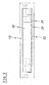
- FIG 1 illustrates a rear view of a decorative cover 10 for a front panel according to a first embodiment of the present invention.
- the front panel is provided for a domestic appliance.
- the decorative cover 10 is formed as a rectangular sheet and comprises four round holes 24.
- the round holes 24 are provided for receiving knobs or shafts of said knobs.
- the decorative cover 10 is made of glass.
- the decorative cover 10 may be made of plastics.
- a glue bead 18 is applied at an outer portion of the rear side of the decorative cover 10.
- the glue bead 18 has the form of a rectangular frame.
- An adhesive tape or a pierced adhesive foil may be used instead of said glue bead 18.
- the application of the glue bead 18 onto the decorative cover 10 is the first step of assembling the front panel of the first embodiment.
- FIG 2 illustrates a rear view of a support plate 12 with the decorative cover 10 for the front panel according to the first embodiment of the present invention.
- the support plate 12 is substantially formed as a rectangular sheet.
- a rectangular cutout is arranged in the central portion of the support plate 12. Said rectangular cutout is marginally smaller than the decorative cover 10 attached at the front side of the support plate 12.
- the rectangular cutout is enclosed by an embossing 22.
- the embossing 22 is provided for receiving the glue bead 18 of the decorative cover 10. The deepness of the embossing 22 defines the thickness of the glue bead 18 between the rear side of the decorative cover 10 and the front side of the support plate 12.
- the assembly of the support plate 12 and the decorative cover 10 is the second step of assembling the front panel of the first embodiment.
- FIG 3 illustrates a rear view of the support plate 12 with the decorative cover 10 for the front panel according to the first embodiment of the present invention.
- FIG 3 shows the same support plate 12 and the same decorative cover 10 as in FIG 2 .
- a further glue bead 20 is arranged on the rear side of the support plate 12.
- the glue bead 20 has the form of a rectangular frame and two transverse joints 26.
- the rectangular frame of the glue bead 20 has substantially the same size as the rectangular frame of the glue bead 18.
- an adhesive tape or a pierced adhesive foil may be used instead of the glue bead 20.
- the applying of the glue bead 20 onto the support plate 12 is the third step of assembling the front panel of the first embodiment.
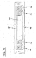
- FIG 4 illustrates a rear view of the support plate 12 with the decorative cover 10 and a holding frame 16 for the front panel according to the first embodiment of the present invention.
- the holding frame 16 is attached in a central portion of the rear side of the support plate 12.
- the holding frame 16 is fixed by the glue bead 20.
- knob housings 14 are also attached at the rear side of the support plate 12. Two knob housings 14 are arranged side-by-side on the left and right sides of the holding frame 16 in each case. Each knob housing 14 corresponds with one of the round holes 24 of the decorative cover 10.
- the knob housings 14 are also fixed by the glue bead 20.
- the fixing of the holding frame 16 and the knob housings 14 at the support plate 12 is the fourth step of assembling the front panel of the first embodiment.
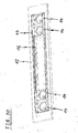
- FIG 5 illustrates a sectional side view of the support plate 12 with the decorative cover 10 and the holding frame 16 for the front panel according to the first embodiment of the present invention.
- FIG 5 clarifies the arrangement of the decorative cover 10, the support plate 12, the holding frame 16 and the glue beads 18 and 20.
- the decorative cover 10 is the foremost component of the front panel.
- the glue bead 18 between the decorative cover 10 and the support plate 12 is arranged in a space provided by the embossing 22.
- the decorative cover 10 lies directly against the support plate 12.
- the glue bead 20 between the support plate 12 and the holding frame 16 is arranged at rear side of the embossing 22 and opposite to the glue bead 18.
- FIG 6 illustrates a rear view of the decorative cover 10 for the front panel according to a second embodiment of the present invention. Same and similar components have the same reference numerals as in the first embodiment.
- the decorative cover 10 is formed as a rectangular sheet and comprises the four round holes 24.
- the round holes 24 are provided for receiving the knobs or the shafts of said knobs.
- the glue bead 18 is applied at an outer portion of the rear side of the decorative cover 10.
- the glue bead 18 has the form of a rectangular frame. Additionally, the glue bead 18 comprises six transverse joints 26, so that the round holes 24 are enclosed by the glue bead 18.
- an adhesive tape or a pierced adhesive foil may be used instead of said glue bead 18.
- the application of the glue bead 18 onto the decorative cover 10 is the first step of assembling the front panel of the second embodiment.
- FIG 7 illustrates a rear view of the support plate 12 with the decorative cover 10 for the front panel according to the second embodiment of the present invention.
- the support plate 12 of the second embodiment is similarly formed as the support plate 12 of the first embodiment.
- the embossing 22 comprises a plurality of holes 28. A part of the glue bead 18 expands through said holes 28, when the support plate 12 is put onto the decorative cover 10.
- the deepness of the embossing 22 defines the thickness of the glue bead 18 between the rear side of the decorative cover 10 and the front side of the support plate 12. That part of the glue bead 18 expanded through the holes 28 forms the glue bead 20 on the rear side of the support plate 12.
- the assembly of the support plate 12 and the decorative cover 10 is the second step of assembling the front panel of the second embodiment.
- FIG 8 illustrates a rear view of the support plate 12 with the decorative cover 10 and the holding frame 16 for the front panel according to the second embodiment of the present invention.
- the holding frame 16 and the four knob housings 14 are attached at the rear side of the support plate 12 in a similar way as in the first embodiment.
- the glue bead 20 between the support plate 12 on the one hand and the holding frame 16 and four knob housings 14 on the other hand is formed by the expansion of the glue bead 18 through the holes 28.
- the fixing of the holding frame 16 and the knob housings 14 at the support plate 12 is the third step of assembling the front panel of the second embodiment.
- FIG 9 illustrates a rear view of the decorative cover 10 for the front panel according to a third embodiment of the present invention.
- the glue bead 18 is applied at an outer portion of the rear side of the decorative cover 10 and has the form of a rectangular frame. Further, the glue bead 18 comprises the six transverse joints 26, so that the round holes 24 are enclosed by the glue bead 18 as in the second embodiment. Additionally, the glue bead 18 comprises a number of contractions 30 in its upper and lower parts. Said contractions 30 are provided in order to obtain places for glue dots.
- the application of the glue bead 18 onto the decorative cover 10 is the first step of assembling the front panel of the third embodiment.
- FIG 10 illustrates a rear view of the support plate 12 with the decorative cover 10 for the front panel according to the third embodiment of the present invention.
- the support plate 12 of the third embodiment has the same form as the support plate 12 of the second embodiment.
- a part of the glue bead 18 expands through the holes 28 in the embossing 22, except at the positions of the contractions 30 of the glue bead 18.
- the deepness of the embossing 22 defines the thickness of the glue bead 18 between the rear side of the decorative cover 10 and the front side of the support plate 12.
- the positions of the contractions 30 are provided for gluing dots of hot glue or UV glue.
- the assembly of the support plate 12 and the decorative cover 10 is the second step of assembling the front panel of the third embodiment.
- FIG 11 illustrates a rear view of the support plate 12 with the decorative cover 10 and the holding frame for the front panel according to the third embodiment of the present invention.
- the holding frame 16 and the four knob housings 14 are attached at the rear side of the support plate 12 in a similar way as in the second embodiment. Now the glue dots of hot glue or UV glue are set at the positions of the contractions 30. The holding frame 16 and the knob housings 14 are hold for a few seconds up to the glue of the gluing dots is hardened. In this way, a bending of the parts can be compensated. Thus, the assembly can be handled directly after the gluing process, since the holding frame 16 and the knob housings 14 are prefixed.
- the fixing of the holding frame 16 and the knob housings 14 at the support plate 12 is the third step of assembling the front panel of the third embodiment.
- FIG 12 illustrates a rear view of the decorative cover 10 and the support plate 12 for the front panel according to a fourth embodiment of the present invention.
- the support plate 12 is put onto the decorative cover 10. This is the first step of assembling the front panel of the fourth embodiment.
- FIG 13 illustrates a rear view of the decorative cover 10 and the support plate 12 with a glue bead 32 the front panel according to the fourth embodiment of the present invention.
- the glue bead 32 is applied onto the decorative cover 10.
- the glue bead 32 has the form of a rectangular frame.
- the glue bead 32 is inside the rectangular cutout of the support plate 12.
- an adhesive tape or a pierced adhesive foil may be used.
- FIG 14 illustrates a perspective front view of the knob housing 14 for the front panel according to the fourth embodiment of the present invention.
- Contact surfaces 34 and distance elements 36 are arranged at the front side of the knob housing 14.
- the contact surfaces 34 are arranged in lines at the upper and lower end portions of the front side, respectively.
- the distance elements 36 are arranged between the upper and lower lines of the contact surfaces 34.
- the contact surfaces 34 are provided to lie against the rear side of the support plate 12.
- the distance elements 36 are provided to lie against the rear side of the decorative cover 10.
- FIG 15 illustrates a perspective front view of the holding frame 16 for the front panel according to the fourth embodiment of the present invention.
- Contact surfaces 38 and distance elements 40 are arranged also at the front side of the holding frame 16.
- the longitudinal contact surfaces 38 form the upper and lower end portions of the front side, respectively.
- the distance elements 40 are arranged between the upper and lower contact surfaces 38.
- the contact surfaces 38 are provided to lie against the rear side of the support plate 12.
- the distance elements 40 are provided to lie against the rear side of the decorative cover 10.
- FIG 16 illustrates a rear view of the support plate 12 with the decorative cover 10 and the holding frame 16 for the front panel according to the fourth embodiment of the present invention.
- the holding frame 16 is attached in a central portion of the rear side of the support plate 12.
- the holding frame 16 is fixed at the decorative cover 10 by the glue bead 32.
- the support plate 12 is clamped between the decorative cover 10 and the holding frame 16.
- the four knob housings 14 are also attached at the rear side of the support plate 12.
- the knob housings 14 are also fixed at the decorative cover 10 by the glue bead 32.
- the support plate 12 is clamped between the decorative cover 10 on the one hand and four knob housings 14 on the other hand.
- the fixing of the holding frame 16 and the knob housings 14 at the support plate 12 is the third step of assembling the front panel of the fourth embodiment.
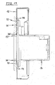
- FIG 17 illustrates a sectional side view of the support plate 12 with the decorative cover 10 and the knob housing 14 for the front panel according to the fourth embodiment of the present invention.
- FIG 17 clarifies the arrangement of the decorative cover 10, the support plate 12, the knob housing 14 and the glue bead 32.
- the decorative cover 10 is the foremost component of the front panel.
- the glue bead 32 between the decorative cover 10 and the knob housing 14 is arranged in a space provided by the distance elements 36.
- the support plate 12 is clamped between the decorative cover 10 on the one hand and four knob housings 14 on the other hand.
- FIG 18 illustrates a sectional side view of the support plate 12 with the decorative cover 10 and the holding frame 16 for the front panel according to the fourth embodiment of the present invention.
- FIG 18 clarifies the arrangement of the decorative cover 10, the support plate 12, the holding frame 16 and the glue bead 32.
- the decorative cover 10 is the foremost component of the front panel.
- the glue bead 32 between the decorative cover 10 and the holding frame 16 is arranged in a space provided by the distance elements 40.
- the support plate 12 is clamped between the decorative cover 10 and the holding frame 16.
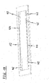
- FIG 19 illustrates a perspective front view of the support plate 12 for the front panel according to a fifth embodiment of the present invention.
- the support plate 12 includes a first embossing 42 at the upper and lower side of the cutout.
- the first embossing 42 is provided for receiving the holding frame 16 and the knob housings 14.
- the first embossing 42 comprises a number of centring elements 46.
- the support plate 12 includes a second embossing 44 enclosing the cutout.
- the second embossing 44 is provided for receiving the glue bead 18.
- FIG 20 illustrates a perspective front view of the support plate 12 with the holding frame 16 and the four knob housings 14 for the front panel according to the fifth embodiment of the present invention.
- the holding frame 16 and the four knob housings 14 are inserted in the cutout of the support plate 12.
- FIG 21 illustrates a perspective rear view of the support plate 12 with the holding frame 16 and the four knob housings 14 for the front panel according to the fifth embodiment of the present invention.
- the holding frame 16 and the knob housings 14 include hooks 48.
- the holding frame 16 and the knob housings 14 are inserted into the support plat 12, so that the contact surfaces 34 and 38 of the holding frame 16 and knob housings 14, respectively, contact the first embossing 42.
- the hooks 48 are provided for a pre-fixing the holding frame 16 and the knob housings 14.
- the glue bead 18 is applied onto the decorative cover 10.
- the support plate 12 with the holding frame 16 and the knob housings 14 is set downwards. The hooks 48 prevent that the holding frame 16 and the knob housings 14 get out of the support plate 12.
- the decorative cover 10 with the glue bead 18 can be set downwards onto the support plate 12 with the holding frame 16 and the knob housings 14, or the glue bead 18 is applied onto the support plate 12 with the holding frame 16 and the knob housings 14 and then the decorative cover 10 is set up.
- the hooks 48 are not necessary.
- FIG 22 illustrates a rear view of the decorative cover 10 for the front panel according to the fifth embodiment of the present invention.
- the decorative cover 10 is formed as a rectangular sheet and comprises the four round holes 24.
- the glue bead 18 is applied at the outer portion of the rear side of the decorative cover 10.
- the glue bead 18 has the form of a rectangular frame. Additionally, the glue bead 18 comprises six transverse joints 26, so that the round holes 24 are enclosed by the glue bead 18.
- an adhesive tape or a pierced adhesive foil may be used instead of said glue bead 18.
- FIG 23 illustrates a sectional side view of the support plate 12 with the decorative cover 10 and the holding frame 16 for the front panel according to the fifth embodiment of the present invention.
- FIG 23 clarifies the structure of the first embossing 42 and the second embossing 44.
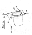
- FIG 24 illustrates a perspective front view of the knob housing 14 for the front panel according to the fifth embodiment of the present invention.
- the knob housing 14 comprises the hooks 48 at its rear side. Said hooks 48 form a snap-in mechanism with the support plate 12.
- FIG 25 illustrates a perspective front view of the holding frame 16 for the front panel according to the fifth embodiment of the present invention.
- the holding frame 16 includes the contact surfaces 38 and the distance elements 40.
- FIG 26 illustrates a partial sectional side view of the support plate 12 with the decorative cover 10 and the holding frame 16 for the front panel according to the fifth embodiment of the present invention.
- FIG 26 clarifies the arrangement of the first embossing 42 and the second embossing 44.
- a part of the glue bead 18 is between the second embossing 44 and the decorative cover 10.
- Another part of the glue bead 18 is between the holding frame 16 and the decorative cover 10.
- the contact surface 34 of the holding frame 16 is supported by the first embossing 42.
- the method of the present invention reduces the number of steps for said method.
- Each embodiment of the inventive method can be performed manually or by a robot.
- the side walls of the decorative cover 10 can be illuminated for display and/or design purposes.
- a microsection at the side walls of the decorative cover 10 may be provided for coupling out of light.
- the possible structures of the microsections allow different effects.
- the coupling of light into the decorative cover 10 may be performed via holes for the knobs and/or keys or via additional holes.
- the decorative cover 10 may at least partially have a concave or convex structure in order to obtain the effects of lenses.
Abstract
- providing a decorative cover (10) made of one or more at least partially transparent materials,
- providing a support plate (12) with at least one cutout corresponding with said decorative cover (10),
- providing at least one holding device (14, 16) for receiving control elements and/or display devices,
- applying a glue bead (18, 32) onto a rear side of the decorative cover (10),
- attaching the support plate (12) onto the rear side of the decorative cover (10), and
- attaching the holding device (14, 16) onto the glue bead (18, 32),
- so that the glue bead (18, 32) is at least partially covered by said support plate (12) and/or the holding device (14, 16).
Description
- The present invention relates to a method for assembling a front panel for a domestic appliance. Further, the present invention relates to a corresponding front panel for a domestic appliance, wherein said front panel comprises a decorative cover made of one or more at least partially transparent materials, a support plate with at least one cutout corresponding with said decorative cover and at least one holding device.
- The front panel for a domestic appliance includes several components. A decorative cover made of glass or another transparent material forms the foremost part of the front panel. A support plate made of a metal sheet of plastics form the central part of the front panel. One or more holding devices are provided for receiving control elements and/or display devices. The holding devices form the rear and/or inner parts of the front panel.
- The assembling of the components for the front panel requires several steps. A number of fasteners are necessary for connecting the components of the front panel. Usually, the neighbouring components of the front panel are connected by fasteners. The connection to the next components is made by further fasteners.
- It is an object of the present invention to provide a method for assembling a front panel for a domestic appliance and a corresponding front panel, wherein the number of assembling steps is reduced.
- The object of the present invention is achieved by the method according to claim 1.
- The present invention relates to a method for assembling a front panel for a domestic appliance, wherein said method comprises the following steps:
- providing a decorative cover made of one or more at least partially transparent materials,
- providing a support plate with at least one cutout corresponding with said decorative cover,
- providing at least one holding device for receiving control elements and/or display devices,
- applying a glue bead onto a rear side of the decorative cover,
- attaching the support plate onto the rear side of the decorative cover, and
- attaching the holding device onto the glue bead,
- so that the glue bead is at least partially covered by the support plate and/or the holding device.
- The main idea of the present invention is that one glue bead allows the connection between three substantial components of the front panel. The glue bead is applied onto the rear side of the decorative cover. The support plate and one or more holding devices are directly fixed on the decorative cover by said glue bead. If only the holding device is fixed on the decorative cover by said glue bead, then the support plate may be clamped between the decorative cover and the holding device, so that the support plate is indirectly fixed on the decorative cover by said glue bead.
- In particular, the provided support plate comprises an embossing enclosing at least partially the cutout of said support plate or an embossing is prepared along the circumference of the cutout of the support plate, wherein the embossing is displaced rearwards.
- Further, the volume of the glue bead is defined by the embossing. Tolerances of the embossing and/or the support plate can be compensated by a variable thickness of the glue bead. Also distorted support plates, which cannot be used for a conventional assembling method, are suitable for the inventive assembling method.
- Preferably, the embossing includes a plurality of holes or a plurality of holes is prepared in the embossing, so that a part of the glue bead swells through said holes during attaching the support plate onto the rear side of the decorative cover. The holes allow that the glue bead is divided into two glue beads on the opposite sides of the embossing. One application of the glue bead results in two glue beads by the holes.
- According to a further embodiment of the present invention the glue bead is prepared with a number of contractions in order to obtain a number of places for glue dots, and the holding device is prefixed onto the rear side of the support plate by said glue dots.
- With the contractions the holding device may be attached onto the rear side of the support plate by glue dots, wherein said glue dots are joined behind the positions of the contractions. In this case the holding device may comprise corresponding holes.
- According to another embodiment of the present invention the support plate is fixed by gluing the holding device onto the decorative cover.
- Further, the support plate and/or the holding device are centred and/or aligned during attaching the support plate and/or the holding device, respectively. The attaching and centring of the support plate and/or holding device may be performed within one step in each case.
- The object of the present invention is further achieved by the front panel according to claim 8.
- The present invention relates to a front panel for a domestic appliance, wherein:
- the front panel comprises a decorative cover made of one or more at least partially transparent materials,
- the front panel comprises a support plate with at least one cutout corresponding with said decorative cover,
- the front panel comprises at least one holding device for receiving control elements and/or display devices,
- a glue bead is applied on a rear side of the decorative cover,
- the support plate is attached on the rear side of the decorative cover, and
- the holding device is attached on the glue bead,
- so that the glue bead is at least partially covered by said support plate and/or the holding device.
- The inventive front panel requires one glue bead for the connection between at least three substantial components of the front panel. The glue bead is applied onto the rear side of the decorative cover. The support plate and one or more holding devices are directly fixed on the decorative cover by said glue bead. If only the holding device is fixed on the decorative cover by said glue bead, then the support plate is clamped between the decorative cover and the holding device, so that the support plate is indirectly fixed on the decorative cover by said glue bead.
- In particular, the support plate comprises an embossing enclosing at least partially the cutout of said support plate, wherein the embossing is displaced rearwards.
- Further, the volume of the glue bead is defined by the embossing. Tolerances of the embossing and/or the support plate are compensated by a variable thickness of the glue bead. The front panel may be made of a distorted support plate, which cannot be used for a conventional assembling method.
- The embossing may include a plurality of holes, so that a part of the glue bead penetrates through said holes. The holes divide the original glue bead into two glue beads on the opposite sides of the embossing.
- The glue bead may comprise a number of contractions, so that a number of places for glue dots is obtained, and the holding device may be prefixed on the rear side of the support plate by said glue dots.
- Preferably, the decorative cover is the foremost component of the front panel. In this case, the side walls of the decorative cover may be illuminated or illuminable for display and/or design purposes.
- Novel and inventive features of the present invention are set forth in the appended claims.
- The present invention will be described in further detail with reference to the drawings, in which
- FIG 1
- illustrates a rear view of a decorative cover for a front panel according to a first embodiment of the present invention,
- FIG 2
- illustrates a rear view of a support plate with the decorative cover for the front panel according to the first embodiment of the present invention,
- FIG 3
- illustrates a rear view of the support plate with the decorative cover for the front panel according to the first embodiment of the present invention,
- FIG 4
- illustrates a rear view of the support plate with the decorative cover and a holding frame and knob housings for the front panel according to the first embodiment of the present invention,
- FIG 5
- illustrates a sectional side view of the support plate with the decorative cover and the holding frame for the front panel according to the first embodiment of the present invention,
- FIG 6
- illustrates a rear view of the decorative cover for the front panel according to a second embodiment of the present invention,
- FIG 7
- illustrates a rear view of the support plate with the decorative cover for the front panel according to the second embodiment of the present invention,
- FIG 8
- illustrates a rear view of the support plate with the decorative cover and the holding frame for the front panel according to the second embodiment of the present invention,
- FIG 9
- illustrates a rear view of the decorative cover for the front panel according to a third embodiment of the present invention,
- FIG 10
- illustrates a rear view of the support plate with the decorative cover for the front panel according to the third embodiment of the present invention,
- FIG 11
- illustrates a rear view of the support plate with the decorative cover and the holding frame for the front panel according to the third embodiment of the present invention,
- FIG 12
- illustrates a rear view of the decorative cover and the support plate for the front panel according to a fourth embodiment of the present invention,
- FIG 13
- illustrates a rear view of the decorative cover and the support plate with a glue bead for the front panel according to the fourth embodiment of the present invention,
- FIG 14
- illustrates a perspective front view of the knob housing for the front panel according to the fourth embodiment of the present invention,
- FIG 15
- illustrates a perspective front view of the holding frame for the front panel according to the fourth embodiment of the present invention,
- FIG 16
- illustrates a rear view of the support plate with the decorative cover and the holding frame for the front panel according to the fourth embodiment of the present invention,
- FIG 17
- illustrates a sectional side view of the support plate with the decorative cover and the knob housing for the front panel according to the fourth embodiment of the present invention,
- FIG 18
- illustrates a sectional side view of the support plate with the decorative cover and the holding frame for the front panel according to the fourth embodiment of the present invention,
- FIG 19
- illustrates a perspective front view of the support plate for the front panel according to a fifth embodiment of the present invention,
- FIG 20
- illustrates a perspective front view of the support plate with the holding frame and knob housings for the front panel according to the fifth embodiment of the present invention,
- FIG 21
- illustrates a perspective rear view of the support plate with the holding frame and knob housings for the front panel according to the fifth embodiment of the present invention,
- FIG 22
- illustrates a rear view of a decorative cover for the front panel according to the fifth embodiment of the present invention,
- FIG 23
- illustrates a sectional side view of the support plate with the decorative cover and the holding frame for the front panel according to the fifth embodiment of the present invention,
- FIG 24
- illustrates a perspective front view of the knob housing for the front panel according to the fifth embodiment of the present invention,
- FIG 25
- illustrates a perspective front view of the holding frame for the front panel according to the fifth embodiment of the present invention, and
- FIG 26
- illustrates a partial sectional side view of the support plate with the decorative cover and the holding frame for the front panel according to the fifth embodiment of the present invention.
-
FIG 1 illustrates a rear view of adecorative cover 10 for a front panel according to a first embodiment of the present invention. The front panel is provided for a domestic appliance. - The
decorative cover 10 is formed as a rectangular sheet and comprises fourround holes 24. The round holes 24 are provided for receiving knobs or shafts of said knobs. In this example, thedecorative cover 10 is made of glass. Alternatively, thedecorative cover 10 may be made of plastics. - A
glue bead 18 is applied at an outer portion of the rear side of thedecorative cover 10. Theglue bead 18 has the form of a rectangular frame. An adhesive tape or a pierced adhesive foil may be used instead of saidglue bead 18. - The application of the
glue bead 18 onto thedecorative cover 10 is the first step of assembling the front panel of the first embodiment. -
FIG 2 illustrates a rear view of asupport plate 12 with thedecorative cover 10 for the front panel according to the first embodiment of the present invention. - The
support plate 12 is substantially formed as a rectangular sheet. A rectangular cutout is arranged in the central portion of thesupport plate 12. Said rectangular cutout is marginally smaller than thedecorative cover 10 attached at the front side of thesupport plate 12. The rectangular cutout is enclosed by anembossing 22. Theembossing 22 is provided for receiving theglue bead 18 of thedecorative cover 10. The deepness of theembossing 22 defines the thickness of theglue bead 18 between the rear side of thedecorative cover 10 and the front side of thesupport plate 12. - The assembly of the
support plate 12 and thedecorative cover 10 is the second step of assembling the front panel of the first embodiment. -
FIG 3 illustrates a rear view of thesupport plate 12 with thedecorative cover 10 for the front panel according to the first embodiment of the present invention.FIG 3 shows thesame support plate 12 and the samedecorative cover 10 as inFIG 2 . - Additionally, a
further glue bead 20 is arranged on the rear side of thesupport plate 12. Theglue bead 20 has the form of a rectangular frame and twotransverse joints 26. The rectangular frame of theglue bead 20 has substantially the same size as the rectangular frame of theglue bead 18. Also in this case, an adhesive tape or a pierced adhesive foil may be used instead of theglue bead 20. - The applying of the
glue bead 20 onto thesupport plate 12 is the third step of assembling the front panel of the first embodiment. -
FIG 4 illustrates a rear view of thesupport plate 12 with thedecorative cover 10 and a holdingframe 16 for the front panel according to the first embodiment of the present invention. - The holding
frame 16 is attached in a central portion of the rear side of thesupport plate 12. The holdingframe 16 is fixed by theglue bead 20. Fourknob housings 14 are also attached at the rear side of thesupport plate 12. Twoknob housings 14 are arranged side-by-side on the left and right sides of the holdingframe 16 in each case. Eachknob housing 14 corresponds with one of the round holes 24 of thedecorative cover 10. Theknob housings 14 are also fixed by theglue bead 20. - The fixing of the holding
frame 16 and theknob housings 14 at thesupport plate 12 is the fourth step of assembling the front panel of the first embodiment. -
FIG 5 illustrates a sectional side view of thesupport plate 12 with thedecorative cover 10 and the holdingframe 16 for the front panel according to the first embodiment of the present invention.FIG 5 clarifies the arrangement of thedecorative cover 10, thesupport plate 12, the holdingframe 16 and theglue beads - The
decorative cover 10 is the foremost component of the front panel. Theglue bead 18 between thedecorative cover 10 and thesupport plate 12 is arranged in a space provided by theembossing 22. Thus, thedecorative cover 10 lies directly against thesupport plate 12. Theglue bead 20 between thesupport plate 12 and the holdingframe 16 is arranged at rear side of theembossing 22 and opposite to theglue bead 18. -
FIG 6 illustrates a rear view of thedecorative cover 10 for the front panel according to a second embodiment of the present invention. Same and similar components have the same reference numerals as in the first embodiment. - The
decorative cover 10 is formed as a rectangular sheet and comprises the four round holes 24. The round holes 24 are provided for receiving the knobs or the shafts of said knobs. - The
glue bead 18 is applied at an outer portion of the rear side of thedecorative cover 10. Theglue bead 18 has the form of a rectangular frame. Additionally, theglue bead 18 comprises sixtransverse joints 26, so that the round holes 24 are enclosed by theglue bead 18. Alternatively, an adhesive tape or a pierced adhesive foil may be used instead of saidglue bead 18. - The application of the
glue bead 18 onto thedecorative cover 10 is the first step of assembling the front panel of the second embodiment. -
FIG 7 illustrates a rear view of thesupport plate 12 with thedecorative cover 10 for the front panel according to the second embodiment of the present invention. - The
support plate 12 of the second embodiment is similarly formed as thesupport plate 12 of the first embodiment. Additionally, theembossing 22 comprises a plurality ofholes 28. A part of theglue bead 18 expands through saidholes 28, when thesupport plate 12 is put onto thedecorative cover 10. The deepness of theembossing 22 defines the thickness of theglue bead 18 between the rear side of thedecorative cover 10 and the front side of thesupport plate 12. That part of theglue bead 18 expanded through theholes 28 forms theglue bead 20 on the rear side of thesupport plate 12. - The assembly of the
support plate 12 and thedecorative cover 10 is the second step of assembling the front panel of the second embodiment. -
FIG 8 illustrates a rear view of thesupport plate 12 with thedecorative cover 10 and the holdingframe 16 for the front panel according to the second embodiment of the present invention. - The holding
frame 16 and the fourknob housings 14 are attached at the rear side of thesupport plate 12 in a similar way as in the first embodiment. However, theglue bead 20 between thesupport plate 12 on the one hand and the holdingframe 16 and fourknob housings 14 on the other hand is formed by the expansion of theglue bead 18 through theholes 28. - The fixing of the holding
frame 16 and theknob housings 14 at thesupport plate 12 is the third step of assembling the front panel of the second embodiment. -
FIG 9 illustrates a rear view of thedecorative cover 10 for the front panel according to a third embodiment of the present invention. - The
glue bead 18 is applied at an outer portion of the rear side of thedecorative cover 10 and has the form of a rectangular frame. Further, theglue bead 18 comprises the sixtransverse joints 26, so that the round holes 24 are enclosed by theglue bead 18 as in the second embodiment. Additionally, theglue bead 18 comprises a number ofcontractions 30 in its upper and lower parts. Saidcontractions 30 are provided in order to obtain places for glue dots. - The application of the
glue bead 18 onto thedecorative cover 10 is the first step of assembling the front panel of the third embodiment. -
FIG 10 illustrates a rear view of thesupport plate 12 with thedecorative cover 10 for the front panel according to the third embodiment of the present invention. - The
support plate 12 of the third embodiment has the same form as thesupport plate 12 of the second embodiment. When thesupport plate 12 is put onto thedecorative cover 10, then a part of theglue bead 18 expands through theholes 28 in theembossing 22, except at the positions of thecontractions 30 of theglue bead 18. The deepness of theembossing 22 defines the thickness of theglue bead 18 between the rear side of thedecorative cover 10 and the front side of thesupport plate 12. The positions of thecontractions 30 are provided for gluing dots of hot glue or UV glue. - The assembly of the
support plate 12 and thedecorative cover 10 is the second step of assembling the front panel of the third embodiment. -
FIG 11 illustrates a rear view of thesupport plate 12 with thedecorative cover 10 and the holding frame for the front panel according to the third embodiment of the present invention. - The holding
frame 16 and the fourknob housings 14 are attached at the rear side of thesupport plate 12 in a similar way as in the second embodiment. Now the glue dots of hot glue or UV glue are set at the positions of thecontractions 30. The holdingframe 16 and theknob housings 14 are hold for a few seconds up to the glue of the gluing dots is hardened. In this way, a bending of the parts can be compensated. Thus, the assembly can be handled directly after the gluing process, since the holdingframe 16 and theknob housings 14 are prefixed. - The fixing of the holding
frame 16 and theknob housings 14 at thesupport plate 12 is the third step of assembling the front panel of the third embodiment. -
FIG 12 illustrates a rear view of thedecorative cover 10 and thesupport plate 12 for the front panel according to a fourth embodiment of the present invention. - In this embodiment the
support plate 12 is put onto thedecorative cover 10. This is the first step of assembling the front panel of the fourth embodiment. -
FIG 13 illustrates a rear view of thedecorative cover 10 and thesupport plate 12 with aglue bead 32 the front panel according to the fourth embodiment of the present invention. - In a second step of the fourth embodiment the
glue bead 32 is applied onto thedecorative cover 10. Theglue bead 32 has the form of a rectangular frame. Theglue bead 32 is inside the rectangular cutout of thesupport plate 12. Instead of theglue bead 32, an adhesive tape or a pierced adhesive foil may be used. -
FIG 14 illustrates a perspective front view of theknob housing 14 for the front panel according to the fourth embodiment of the present invention. - Contact surfaces 34 and
distance elements 36 are arranged at the front side of theknob housing 14. The contact surfaces 34 are arranged in lines at the upper and lower end portions of the front side, respectively. Thedistance elements 36 are arranged between the upper and lower lines of the contact surfaces 34. The contact surfaces 34 are provided to lie against the rear side of thesupport plate 12. Thedistance elements 36 are provided to lie against the rear side of thedecorative cover 10. -
FIG 15 illustrates a perspective front view of the holdingframe 16 for the front panel according to the fourth embodiment of the present invention. - Contact surfaces 38 and
distance elements 40 are arranged also at the front side of the holdingframe 16. The longitudinal contact surfaces 38 form the upper and lower end portions of the front side, respectively. Thedistance elements 40 are arranged between the upper and lower contact surfaces 38. The contact surfaces 38 are provided to lie against the rear side of thesupport plate 12. Thedistance elements 40 are provided to lie against the rear side of thedecorative cover 10. -
FIG 16 illustrates a rear view of thesupport plate 12 with thedecorative cover 10 and the holdingframe 16 for the front panel according to the fourth embodiment of the present invention. - The holding
frame 16 is attached in a central portion of the rear side of thesupport plate 12. The holdingframe 16 is fixed at thedecorative cover 10 by theglue bead 32. Thus, thesupport plate 12 is clamped between thedecorative cover 10 and the holdingframe 16. - The four
knob housings 14 are also attached at the rear side of thesupport plate 12. Theknob housings 14 are also fixed at thedecorative cover 10 by theglue bead 32. Thus, thesupport plate 12 is clamped between thedecorative cover 10 on the one hand and fourknob housings 14 on the other hand. - The fixing of the holding
frame 16 and theknob housings 14 at thesupport plate 12 is the third step of assembling the front panel of the fourth embodiment. -
FIG 17 illustrates a sectional side view of thesupport plate 12 with thedecorative cover 10 and theknob housing 14 for the front panel according to the fourth embodiment of the present invention.FIG 17 clarifies the arrangement of thedecorative cover 10, thesupport plate 12, theknob housing 14 and theglue bead 32. - The
decorative cover 10 is the foremost component of the front panel. Theglue bead 32 between thedecorative cover 10 and theknob housing 14 is arranged in a space provided by thedistance elements 36. Thesupport plate 12 is clamped between thedecorative cover 10 on the one hand and fourknob housings 14 on the other hand. -
FIG 18 illustrates a sectional side view of thesupport plate 12 with thedecorative cover 10 and the holdingframe 16 for the front panel according to the fourth embodiment of the present invention.FIG 18 clarifies the arrangement of thedecorative cover 10, thesupport plate 12, the holdingframe 16 and theglue bead 32. - The
decorative cover 10 is the foremost component of the front panel. Theglue bead 32 between thedecorative cover 10 and the holdingframe 16 is arranged in a space provided by thedistance elements 40. Thesupport plate 12 is clamped between thedecorative cover 10 and the holdingframe 16. -
FIG 19 illustrates a perspective front view of thesupport plate 12 for the front panel according to a fifth embodiment of the present invention. - The
support plate 12 includes afirst embossing 42 at the upper and lower side of the cutout. Thefirst embossing 42 is provided for receiving the holdingframe 16 and theknob housings 14. Thefirst embossing 42 comprises a number ofcentring elements 46. Further, thesupport plate 12 includes asecond embossing 44 enclosing the cutout. Thesecond embossing 44 is provided for receiving theglue bead 18. -
FIG 20 illustrates a perspective front view of thesupport plate 12 with the holdingframe 16 and the fourknob housings 14 for the front panel according to the fifth embodiment of the present invention. The holdingframe 16 and the fourknob housings 14 are inserted in the cutout of thesupport plate 12. -
FIG 21 illustrates a perspective rear view of thesupport plate 12 with the holdingframe 16 and the fourknob housings 14 for the front panel according to the fifth embodiment of the present invention. The holdingframe 16 and theknob housings 14 include hooks 48. - The holding
frame 16 and theknob housings 14 are inserted into thesupport plat 12, so that the contact surfaces 34 and 38 of the holdingframe 16 andknob housings 14, respectively, contact thefirst embossing 42. Thehooks 48 are provided for a pre-fixing the holdingframe 16 and theknob housings 14. Theglue bead 18 is applied onto thedecorative cover 10. Thesupport plate 12 with the holdingframe 16 and theknob housings 14 is set downwards. Thehooks 48 prevent that the holdingframe 16 and theknob housings 14 get out of thesupport plate 12. - Alternatively, the
decorative cover 10 with theglue bead 18 can be set downwards onto thesupport plate 12 with the holdingframe 16 and theknob housings 14, or theglue bead 18 is applied onto thesupport plate 12 with the holdingframe 16 and theknob housings 14 and then thedecorative cover 10 is set up. In this case, thehooks 48 are not necessary. -
FIG 22 illustrates a rear view of thedecorative cover 10 for the front panel according to the fifth embodiment of the present invention. Thedecorative cover 10 is formed as a rectangular sheet and comprises the four round holes 24. - The
glue bead 18 is applied at the outer portion of the rear side of thedecorative cover 10. Theglue bead 18 has the form of a rectangular frame. Additionally, theglue bead 18 comprises sixtransverse joints 26, so that the round holes 24 are enclosed by theglue bead 18. Alternatively, an adhesive tape or a pierced adhesive foil may be used instead of saidglue bead 18. -
FIG 23 illustrates a sectional side view of thesupport plate 12 with thedecorative cover 10 and the holdingframe 16 for the front panel according to the fifth embodiment of the present invention.FIG 23 clarifies the structure of thefirst embossing 42 and thesecond embossing 44. -
FIG 24 illustrates a perspective front view of theknob housing 14 for the front panel according to the fifth embodiment of the present invention. Theknob housing 14 comprises thehooks 48 at its rear side. Said hooks 48 form a snap-in mechanism with thesupport plate 12. -
FIG 25 illustrates a perspective front view of the holdingframe 16 for the front panel according to the fifth embodiment of the present invention. The holdingframe 16 includes the contact surfaces 38 and thedistance elements 40. -
FIG 26 illustrates a partial sectional side view of thesupport plate 12 with thedecorative cover 10 and the holdingframe 16 for the front panel according to the fifth embodiment of the present invention.FIG 26 clarifies the arrangement of thefirst embossing 42 and thesecond embossing 44. A part of theglue bead 18 is between thesecond embossing 44 and thedecorative cover 10. Another part of theglue bead 18 is between the holdingframe 16 and thedecorative cover 10. Thecontact surface 34 of the holdingframe 16 is supported by thefirst embossing 42. - The method of the present invention reduces the number of steps for said method. Each embodiment of the inventive method can be performed manually or by a robot.
- Since the
decorative cover 10 is smaller than thesupport plate 12, the side walls of thedecorative cover 10 can be illuminated for display and/or design purposes. A microsection at the side walls of thedecorative cover 10 may be provided for coupling out of light. The possible structures of the microsections allow different effects. The coupling of light into thedecorative cover 10 may be performed via holes for the knobs and/or keys or via additional holes. Thedecorative cover 10 may at least partially have a concave or convex structure in order to obtain the effects of lenses. -
- 10
- decorative cover
- 12
- support plate
- 14
- knob housing
- 16
- holding frame
- 18
- glue bead on the decorative cover
- 20
- glue bead on the support plate
- 22
- embossing
- 24
- round hole
- 26
- transverse joint
- 28
- hole in the embossing
- 30
- contraction
- 32
- glue bead on the decorative cover
- 34
- contact surface
- 36
- distance element
- 38
- contact surface
- 40
- distance element
- 42
- first embossing
- 44
- second embossing
- 46
- centring element
- 48
- hook
Claims (15)
- A method for assembling a front panel for a domestic appliance, wherein said method comprises the following steps:- providing a decorative cover (10) made of one or more at least partially transparent materials,- providing a support plate (12) with at least one cutout corresponding with said decorative cover (10),- providing at least one holding device (14, 16) for receiving control elements and/or display devices,- applying a glue bead (18, 32) onto a rear side of the decorative cover (10),- attaching the support plate (12) onto the rear side of the decorative cover (10), and- attaching the holding device (14, 16) onto the glue bead (18, 32),- so that the glue bead (18, 32) is at least partially covered by the support plate (12) and/or the holding device (14, 16).
- The method according to claim 1,
characterized in, that
the provided support plate (12) comprises an embossing (22) enclosing at least partially the cutout of said support plate (12) or an embossing (22) is prepared along the circumference of the cutout of the support plate (12), wherein the embossing (22) is displaced rearwards. - The method according to claim 2,
characterized in, that
the volume of the glue bead (18) is defined by the embossing (22). - The method according to claim 2 or 3,
characterized in, that
the embossing (22) includes a plurality of holes (28) or a plurality of holes (28) is prepared in the embossing (22), so that a part of the glue bead (18) swells through said holes (28) during attaching the support plate (12) onto the rear side of the decorative cover (10). - The method according to any one of the preceding claims,
characterized in, that
the glue bead (18) is prepared with a number of contractions (30) in order to obtain a number of places for glue dots, and the holding device (14, 16) is prefixed onto the rear side of the support plate (12) by said glue dots. - The method according to claim 5,
characterized in, that
the support plate (12) is fixed by gluing the holding device (14, 16) onto the decorative cover (10). - The method according to any one of the preceding claims,
characterized in, that
the support plate (12) and/or the holding device (14, 16) are centred and/or aligned during attaching the support plate (12) and/or the holding device (14, 16), respectively. - A front panel for a domestic appliance, wherein:- the front panel comprises a decorative cover (10) made of one or more at least partially transparent materials,- the front panel comprises a support plate (12) with at least one cutout corresponding with said decorative cover (10),- the front panel comprises at least one holding device (14, 16) for receiving control elements and/or display devices,- a glue bead (18, 32) is applied on a rear side of the decorative cover (10),- the support plate (12) is attached on the rear side of the decorative cover (10), and- the holding device (14, 16) is attached on the glue bead (18, 32),- so that the glue bead (18, 32) is at least partially covered by the support plate (12) and/or the holding device (14, 16).
- The front panel according to claim 8,
characterized in, that
the support plate (12) comprises an embossing (22) enclosing at least partially the cutout of said support plate (12), wherein the embossing (22) is displaced rearwards. - The front panel according to claim 9,
characterized in, that
the volume of the glue bead (18) is defined by the embossing (22). - The front panel according to claim 9 or 10,
characterized in, that
the embossing (22) includes a plurality of holes (28), so that a part of the glue bead (18) penetrates through said holes (28). - The front panel according to any one of the claims 8 to 11,
characterized in, that
the glue bead (18) comprises a number of contractions (30), so that a number of places for glue dots is obtained, and the holding device (14, 16) is prefixed on the rear side of the support plate (12) by said glue dots. - The front panel according to claim 12,
characterized in, that
the support plate (12) is fixed by the holding device (14, 16) glued on the decorative cover (10). - The front panel according to any one of the claims 8 to 13,
characterized in, that
the decorative cover (10 is the foremost component of the front panel. - The front panel according to claim 14,
characterized in, that
the side walls of the decorative cover (10) are illuminated or illuminable for display and/or design purposes.
Priority Applications (3)
| Application Number | Priority Date | Filing Date | Title |
|---|---|---|---|
| EP11185162.2A EP2581485B1 (en) | 2011-10-14 | 2011-10-14 | A method for assembling a front panel for a domestic appliance and a corresponding front panel |
| PL11185162T PL2581485T3 (en) | 2011-10-14 | 2011-10-14 | A method for assembling a front panel for a domestic appliance and a corresponding front panel |
| ES11185162.2T ES2496316T3 (en) | 2011-10-14 | 2011-10-14 | Mounting method of a front panel for a domestic appliance and corresponding front panel |
Applications Claiming Priority (1)
| Application Number | Priority Date | Filing Date | Title |
|---|---|---|---|
| EP11185162.2A EP2581485B1 (en) | 2011-10-14 | 2011-10-14 | A method for assembling a front panel for a domestic appliance and a corresponding front panel |
Publications (2)
| Publication Number | Publication Date |
|---|---|
| EP2581485A1 true EP2581485A1 (en) | 2013-04-17 |
| EP2581485B1 EP2581485B1 (en) | 2014-06-11 |
Family
ID=44862559
Family Applications (1)
| Application Number | Title | Priority Date | Filing Date |
|---|---|---|---|
| EP11185162.2A Active EP2581485B1 (en) | 2011-10-14 | 2011-10-14 | A method for assembling a front panel for a domestic appliance and a corresponding front panel |
Country Status (3)
| Country | Link |
|---|---|
| EP (1) | EP2581485B1 (en) |
| ES (1) | ES2496316T3 (en) |
| PL (1) | PL2581485T3 (en) |
Cited By (7)
| Publication number | Priority date | Publication date | Assignee | Title |
|---|---|---|---|---|
| EP3165668A1 (en) * | 2015-11-02 | 2017-05-10 | LG Electronics Inc. | Laundry treating apparatus |
| WO2018077057A1 (en) * | 2016-10-27 | 2018-05-03 | 青岛海尔洗衣机有限公司 | Control-panel structure and household appliance device |
| US9970143B2 (en) | 2015-11-02 | 2018-05-15 | Lg Electronics Inc. | Laundry treating apparatus and method of fabricating a laundry treating apparatus door |
| US10047473B2 (en) | 2015-11-02 | 2018-08-14 | Lg Electronics Inc. | Laundry treating apparatus |
| US10344422B2 (en) | 2015-11-02 | 2019-07-09 | Lg Electronics Inc. | Laundry treating apparatus |
| US10711389B2 (en) | 2015-11-02 | 2020-07-14 | Lg Electronics Inc. | Door hinge of a laundry treating apparatus |
| US10815602B2 (en) | 2015-11-02 | 2020-10-27 | Lg Electronics Inc. | Laundry treating apparatus |
Citations (5)
| Publication number | Priority date | Publication date | Assignee | Title |
|---|---|---|---|---|
| DE29610047U1 (en) * | 1996-06-07 | 1996-08-22 | Schwarzbich Joerg | Control console for household appliances |
| US5584563A (en) * | 1996-01-16 | 1996-12-17 | General Electric Company | Appliance control assembly |
| EP1639935A2 (en) * | 2004-09-23 | 2006-03-29 | Miele & Cie. KG | Box-shaped control panel. |
| DE102005024934A1 (en) * | 2005-05-31 | 2006-12-07 | BSH Bosch und Siemens Hausgeräte GmbH | A method for indicating the selection options for a domestic appliance has a sandwich of transparent layers carrying universal and language data separately around the control knob |
| EP1990698A1 (en) * | 2007-05-10 | 2008-11-12 | Electrolux Home Products Corporation N.V. | Improved modular control panel for a household appliance |
-
2011
- 2011-10-14 PL PL11185162T patent/PL2581485T3/en unknown
- 2011-10-14 EP EP11185162.2A patent/EP2581485B1/en active Active
- 2011-10-14 ES ES11185162.2T patent/ES2496316T3/en active Active
Patent Citations (5)
| Publication number | Priority date | Publication date | Assignee | Title |
|---|---|---|---|---|
| US5584563A (en) * | 1996-01-16 | 1996-12-17 | General Electric Company | Appliance control assembly |
| DE29610047U1 (en) * | 1996-06-07 | 1996-08-22 | Schwarzbich Joerg | Control console for household appliances |
| EP1639935A2 (en) * | 2004-09-23 | 2006-03-29 | Miele & Cie. KG | Box-shaped control panel. |
| DE102005024934A1 (en) * | 2005-05-31 | 2006-12-07 | BSH Bosch und Siemens Hausgeräte GmbH | A method for indicating the selection options for a domestic appliance has a sandwich of transparent layers carrying universal and language data separately around the control knob |
| EP1990698A1 (en) * | 2007-05-10 | 2008-11-12 | Electrolux Home Products Corporation N.V. | Improved modular control panel for a household appliance |
Cited By (15)
| Publication number | Priority date | Publication date | Assignee | Title |
|---|---|---|---|---|
| US10094063B2 (en) | 2015-11-02 | 2018-10-09 | Lg Electronics Inc. | Laundry treating apparatus and method of fabricating a laundry treating apparatus door |
| US10266983B2 (en) | 2015-11-02 | 2019-04-23 | Lg Electronics Inc. | Laundry treating apparatus |
| US9970143B2 (en) | 2015-11-02 | 2018-05-15 | Lg Electronics Inc. | Laundry treating apparatus and method of fabricating a laundry treating apparatus door |
| US10000879B2 (en) | 2015-11-02 | 2018-06-19 | Lg Electronics Inc. | Laundry treating apparatus |
| US10006159B2 (en) | 2015-11-02 | 2018-06-26 | Lg Electronics Inc. | Laundry treating apparatus |
| US10047473B2 (en) | 2015-11-02 | 2018-08-14 | Lg Electronics Inc. | Laundry treating apparatus |
| USRE49269E1 (en) | 2015-11-02 | 2022-11-01 | Lg Electronics Inc. | Laundry treating apparatus |
| US10161076B2 (en) | 2015-11-02 | 2018-12-25 | Lg Electronics Inc. | Laundry treating apparatus |
| EP3165668A1 (en) * | 2015-11-02 | 2017-05-10 | LG Electronics Inc. | Laundry treating apparatus |
| US10344422B2 (en) | 2015-11-02 | 2019-07-09 | Lg Electronics Inc. | Laundry treating apparatus |
| US10711389B2 (en) | 2015-11-02 | 2020-07-14 | Lg Electronics Inc. | Door hinge of a laundry treating apparatus |
| US10815602B2 (en) | 2015-11-02 | 2020-10-27 | Lg Electronics Inc. | Laundry treating apparatus |
| EP3845701A1 (en) * | 2015-11-02 | 2021-07-07 | LG Electronics Inc. | Laundry treating apparatus |
| EP3988700A1 (en) * | 2015-11-02 | 2022-04-27 | LG Electronics Inc. | Laundry treating apparatus |
| WO2018077057A1 (en) * | 2016-10-27 | 2018-05-03 | 青岛海尔洗衣机有限公司 | Control-panel structure and household appliance device |
Also Published As
| Publication number | Publication date |
|---|---|
| EP2581485B1 (en) | 2014-06-11 |
| PL2581485T3 (en) | 2014-11-28 |
| ES2496316T3 (en) | 2014-09-18 |
Similar Documents
| Publication | Publication Date | Title |
|---|---|---|
| EP2581485B1 (en) | A method for assembling a front panel for a domestic appliance and a corresponding front panel | |
| WO2009017864A3 (en) | Fastener-free primary structural joint for sandwich panels | |
| US20070277419A1 (en) | Structure of one-piece-form bezel and manufacturing method thereof | |
| JP5126033B2 (en) | Display device | |
| WO2016169200A1 (en) | Face frame for display module, display module, and display device | |
| US10509247B2 (en) | Back panel assembly and display device having the same | |
| US11765841B2 (en) | Control panel for an apparatus, in particular for a domestic appliance, and a method for assembling said control panel | |
| CN102866741B (en) | Touch-screen frame assembly and touch-screen | |
| JP6190972B2 (en) | Display device and manufacturing method of display device | |
| WO2011147532A1 (en) | Method for mounting a panel of an appliance, especially of a domestic appliance | |
| US5808863A (en) | Computer system having quick-detachable recyclable parts and method | |
| JP6205283B2 (en) | Curved display panel holder | |
| EP2530554B1 (en) | Portable electronic device | |
| JP2000514906A (en) | Apparatus for connecting a plastic material accessory to a module self-supporting element and fixing the module self-supporting element to a vehicle body structural element | |
| KR100381084B1 (en) | Flat panel display module and display unit having such a flat panel display module | |
| JP4637673B2 (en) | Door panel | |
| KR20060084585A (en) | Plasma display device | |
| CN108535894B (en) | Fitting strength test fixture | |
| KR20170079001A (en) | Case for display panel and display device comprising the same | |
| JP6594158B2 (en) | Electronic device and manufacturing method thereof | |
| TWI398891B (en) | Electrical device and keying holder structure thereof | |
| KR101518198B1 (en) | manufacture method of multidirectional wall clock and multidirectional wall clock | |
| CN103955094B (en) | Frame mechanism for optical equipment | |
| JP7194968B2 (en) | Gas stove and method for manufacturing gas stove | |
| JP2010084414A (en) | Door with lighting section |
Legal Events
| Date | Code | Title | Description |
|---|---|---|---|
| PUAI | Public reference made under article 153(3) epc to a published international application that has entered the european phase |
Free format text: ORIGINAL CODE: 0009012 |
|
| 17P | Request for examination filed |
Effective date: 20120328 |
|
| AK | Designated contracting states |
Kind code of ref document: A1 Designated state(s): AL AT BE BG CH CY CZ DE DK EE ES FI FR GB GR HR HU IE IS IT LI LT LU LV MC MK MT NL NO PL PT RO RS SE SI SK SM TR |
|
| AX | Request for extension of the european patent |
Extension state: BA ME |
|
| GRAP | Despatch of communication of intention to grant a patent |
Free format text: ORIGINAL CODE: EPIDOSNIGR1 |
|
| RIC1 | Information provided on ipc code assigned before grant |
Ipc: A47L 15/42 20060101ALI20131129BHEP Ipc: D06F 39/00 20060101AFI20131129BHEP |
|
| INTG | Intention to grant announced |
Effective date: 20140108 |
|
| GRAS | Grant fee paid |
Free format text: ORIGINAL CODE: EPIDOSNIGR3 |
|
| GRAA | (expected) grant |
Free format text: ORIGINAL CODE: 0009210 |
|
| STAA | Information on the status of an ep patent application or granted ep patent |
Free format text: STATUS: THE PATENT HAS BEEN GRANTED |
|
| AK | Designated contracting states |
Kind code of ref document: B1 Designated state(s): AL AT BE BG CH CY CZ DE DK EE ES FI FR GB GR HR HU IE IS IT LI LT LU LV MC MK MT NL NO PL PT RO RS SE SI SK SM TR |
|
| REG | Reference to a national code |
Ref country code: GB Ref legal event code: FG4D |
|
| REG | Reference to a national code |
Ref country code: CH Ref legal event code: EP |
|
| REG | Reference to a national code |
Ref country code: IE Ref legal event code: FG4D |
|
| REG | Reference to a national code |
Ref country code: AT Ref legal event code: REF Ref document number: 672325 Country of ref document: AT Kind code of ref document: T Effective date: 20140715 |
|
| REG | Reference to a national code |
Ref country code: DE Ref legal event code: R096 Ref document number: 602011007558 Country of ref document: DE Effective date: 20140724 |
|
| REG | Reference to a national code |
Ref country code: NL Ref legal event code: T3 |
|
| REG | Reference to a national code |
Ref country code: ES Ref legal event code: FG2A Ref document number: 2496316 Country of ref document: ES Kind code of ref document: T3 Effective date: 20140918 |
|
| PG25 | Lapsed in a contracting state [announced via postgrant information from national office to epo] |
Ref country code: NO Free format text: LAPSE BECAUSE OF FAILURE TO SUBMIT A TRANSLATION OF THE DESCRIPTION OR TO PAY THE FEE WITHIN THE PRESCRIBED TIME-LIMIT Effective date: 20140911 Ref country code: GR Free format text: LAPSE BECAUSE OF FAILURE TO SUBMIT A TRANSLATION OF THE DESCRIPTION OR TO PAY THE FEE WITHIN THE PRESCRIBED TIME-LIMIT Effective date: 20140912 Ref country code: LT Free format text: LAPSE BECAUSE OF FAILURE TO SUBMIT A TRANSLATION OF THE DESCRIPTION OR TO PAY THE FEE WITHIN THE PRESCRIBED TIME-LIMIT Effective date: 20140611 Ref country code: FI Free format text: LAPSE BECAUSE OF FAILURE TO SUBMIT A TRANSLATION OF THE DESCRIPTION OR TO PAY THE FEE WITHIN THE PRESCRIBED TIME-LIMIT Effective date: 20140611 |
|
| REG | Reference to a national code |
Ref country code: AT Ref legal event code: MK05 Ref document number: 672325 Country of ref document: AT Kind code of ref document: T Effective date: 20140611 |
|
| REG | Reference to a national code |
Ref country code: LT Ref legal event code: MG4D |
|
| PG25 | Lapsed in a contracting state [announced via postgrant information from national office to epo] |
Ref country code: HR Free format text: LAPSE BECAUSE OF FAILURE TO SUBMIT A TRANSLATION OF THE DESCRIPTION OR TO PAY THE FEE WITHIN THE PRESCRIBED TIME-LIMIT Effective date: 20140611 Ref country code: RS Free format text: LAPSE BECAUSE OF FAILURE TO SUBMIT A TRANSLATION OF THE DESCRIPTION OR TO PAY THE FEE WITHIN THE PRESCRIBED TIME-LIMIT Effective date: 20140611 Ref country code: LV Free format text: LAPSE BECAUSE OF FAILURE TO SUBMIT A TRANSLATION OF THE DESCRIPTION OR TO PAY THE FEE WITHIN THE PRESCRIBED TIME-LIMIT Effective date: 20140611 Ref country code: SE Free format text: LAPSE BECAUSE OF FAILURE TO SUBMIT A TRANSLATION OF THE DESCRIPTION OR TO PAY THE FEE WITHIN THE PRESCRIBED TIME-LIMIT Effective date: 20140611 |
|
| REG | Reference to a national code |
Ref country code: PL Ref legal event code: T3 |
|
| PG25 | Lapsed in a contracting state [announced via postgrant information from national office to epo] |
Ref country code: PT Free format text: LAPSE BECAUSE OF FAILURE TO SUBMIT A TRANSLATION OF THE DESCRIPTION OR TO PAY THE FEE WITHIN THE PRESCRIBED TIME-LIMIT Effective date: 20141013 Ref country code: RO Free format text: LAPSE BECAUSE OF FAILURE TO SUBMIT A TRANSLATION OF THE DESCRIPTION OR TO PAY THE FEE WITHIN THE PRESCRIBED TIME-LIMIT Effective date: 20140611 Ref country code: EE Free format text: LAPSE BECAUSE OF FAILURE TO SUBMIT A TRANSLATION OF THE DESCRIPTION OR TO PAY THE FEE WITHIN THE PRESCRIBED TIME-LIMIT Effective date: 20140611 Ref country code: CZ Free format text: LAPSE BECAUSE OF FAILURE TO SUBMIT A TRANSLATION OF THE DESCRIPTION OR TO PAY THE FEE WITHIN THE PRESCRIBED TIME-LIMIT Effective date: 20140611 Ref country code: SK Free format text: LAPSE BECAUSE OF FAILURE TO SUBMIT A TRANSLATION OF THE DESCRIPTION OR TO PAY THE FEE WITHIN THE PRESCRIBED TIME-LIMIT Effective date: 20140611 |
|
| PG25 | Lapsed in a contracting state [announced via postgrant information from national office to epo] |
Ref country code: IS Free format text: LAPSE BECAUSE OF FAILURE TO SUBMIT A TRANSLATION OF THE DESCRIPTION OR TO PAY THE FEE WITHIN THE PRESCRIBED TIME-LIMIT Effective date: 20141011 Ref country code: AT Free format text: LAPSE BECAUSE OF FAILURE TO SUBMIT A TRANSLATION OF THE DESCRIPTION OR TO PAY THE FEE WITHIN THE PRESCRIBED TIME-LIMIT Effective date: 20140611 |
|
| REG | Reference to a national code |
Ref country code: DE Ref legal event code: R026 Ref document number: 602011007558 Country of ref document: DE |
|
| PLBI | Opposition filed |
Free format text: ORIGINAL CODE: 0009260 |
|
| 26 | Opposition filed |
Opponent name: WHIRLPOOL EUROPE SRL Effective date: 20150311 |
|
| PLAX | Notice of opposition and request to file observation + time limit sent |
Free format text: ORIGINAL CODE: EPIDOSNOBS2 |
|
| PG25 | Lapsed in a contracting state [announced via postgrant information from national office to epo] |
Ref country code: DK Free format text: LAPSE BECAUSE OF FAILURE TO SUBMIT A TRANSLATION OF THE DESCRIPTION OR TO PAY THE FEE WITHIN THE PRESCRIBED TIME-LIMIT Effective date: 20140611 |
|
| REG | Reference to a national code |
Ref country code: DE Ref legal event code: R026 Ref document number: 602011007558 Country of ref document: DE Effective date: 20150311 |
|
| PG25 | Lapsed in a contracting state [announced via postgrant information from national office to epo] |
Ref country code: MC Free format text: LAPSE BECAUSE OF FAILURE TO SUBMIT A TRANSLATION OF THE DESCRIPTION OR TO PAY THE FEE WITHIN THE PRESCRIBED TIME-LIMIT Effective date: 20140611 Ref country code: LU Free format text: LAPSE BECAUSE OF FAILURE TO SUBMIT A TRANSLATION OF THE DESCRIPTION OR TO PAY THE FEE WITHIN THE PRESCRIBED TIME-LIMIT Effective date: 20141014 |
|
| REG | Reference to a national code |
Ref country code: IE Ref legal event code: MM4A |
|
| PG25 | Lapsed in a contracting state [announced via postgrant information from national office to epo] |
Ref country code: SI Free format text: LAPSE BECAUSE OF FAILURE TO SUBMIT A TRANSLATION OF THE DESCRIPTION OR TO PAY THE FEE WITHIN THE PRESCRIBED TIME-LIMIT Effective date: 20140611 |
|
| PLBB | Reply of patent proprietor to notice(s) of opposition received |
Free format text: ORIGINAL CODE: EPIDOSNOBS3 |
|
| REG | Reference to a national code |
Ref country code: FR Ref legal event code: PLFP Year of fee payment: 5 |
|
| PG25 | Lapsed in a contracting state [announced via postgrant information from national office to epo] |
Ref country code: IE Free format text: LAPSE BECAUSE OF NON-PAYMENT OF DUE FEES Effective date: 20141014 |
|
| PG25 | Lapsed in a contracting state [announced via postgrant information from national office to epo] |
Ref country code: SM Free format text: LAPSE BECAUSE OF FAILURE TO SUBMIT A TRANSLATION OF THE DESCRIPTION OR TO PAY THE FEE WITHIN THE PRESCRIBED TIME-LIMIT Effective date: 20140611 |
|
| PG25 | Lapsed in a contracting state [announced via postgrant information from national office to epo] |
Ref country code: CY Free format text: LAPSE BECAUSE OF FAILURE TO SUBMIT A TRANSLATION OF THE DESCRIPTION OR TO PAY THE FEE WITHIN THE PRESCRIBED TIME-LIMIT Effective date: 20140611 Ref country code: BG Free format text: LAPSE BECAUSE OF FAILURE TO SUBMIT A TRANSLATION OF THE DESCRIPTION OR TO PAY THE FEE WITHIN THE PRESCRIBED TIME-LIMIT Effective date: 20140611 |
|
| PG25 | Lapsed in a contracting state [announced via postgrant information from national office to epo] |
Ref country code: HU Free format text: LAPSE BECAUSE OF FAILURE TO SUBMIT A TRANSLATION OF THE DESCRIPTION OR TO PAY THE FEE WITHIN THE PRESCRIBED TIME-LIMIT; INVALID AB INITIO Effective date: 20111014 Ref country code: MT Free format text: LAPSE BECAUSE OF FAILURE TO SUBMIT A TRANSLATION OF THE DESCRIPTION OR TO PAY THE FEE WITHIN THE PRESCRIBED TIME-LIMIT Effective date: 20140611 Ref country code: BE Free format text: LAPSE BECAUSE OF FAILURE TO SUBMIT A TRANSLATION OF THE DESCRIPTION OR TO PAY THE FEE WITHIN THE PRESCRIBED TIME-LIMIT Effective date: 20140611 |
|
| REG | Reference to a national code |
Ref country code: FR Ref legal event code: PLFP Year of fee payment: 6 |
|
| APBM | Appeal reference recorded |
Free format text: ORIGINAL CODE: EPIDOSNREFNO |
|
| APAH | Appeal reference modified |
Free format text: ORIGINAL CODE: EPIDOSCREFNO |
|
| REG | Reference to a national code |
Ref country code: FR Ref legal event code: PLFP Year of fee payment: 7 |
|
| PLAB | Opposition data, opponent's data or that of the opponent's representative modified |
Free format text: ORIGINAL CODE: 0009299OPPO |
|
| R26 | Opposition filed (corrected) |
Opponent name: WHIRLPOOL EUROPE SRL Effective date: 20150311 |
|
| PLAB | Opposition data, opponent's data or that of the opponent's representative modified |
Free format text: ORIGINAL CODE: 0009299OPPO |
|
| PG25 | Lapsed in a contracting state [announced via postgrant information from national office to epo] |
Ref country code: MK Free format text: LAPSE BECAUSE OF FAILURE TO SUBMIT A TRANSLATION OF THE DESCRIPTION OR TO PAY THE FEE WITHIN THE PRESCRIBED TIME-LIMIT Effective date: 20140611 |
|
| R26 | Opposition filed (corrected) |
Opponent name: WHIRLPOOL EUROPE SRL Effective date: 20150311 |
|
| REG | Reference to a national code |
Ref country code: FR Ref legal event code: PLFP Year of fee payment: 8 |
|
| PG25 | Lapsed in a contracting state [announced via postgrant information from national office to epo] |
Ref country code: AL Free format text: LAPSE BECAUSE OF FAILURE TO SUBMIT A TRANSLATION OF THE DESCRIPTION OR TO PAY THE FEE WITHIN THE PRESCRIBED TIME-LIMIT Effective date: 20140611 |
|
| PLAB | Opposition data, opponent's data or that of the opponent's representative modified |
Free format text: ORIGINAL CODE: 0009299OPPO |
|
| R26 | Opposition filed (corrected) |
Opponent name: WHIRLPOOL EMEA S.P.A. Effective date: 20150311 |
|
| PLAY | Examination report in opposition despatched + time limit |
Free format text: ORIGINAL CODE: EPIDOSNORE2 |
|
| PLAH | Information related to despatch of examination report in opposition + time limit modified |
Free format text: ORIGINAL CODE: EPIDOSCORE2 |
|
| PLBC | Reply to examination report in opposition received |
Free format text: ORIGINAL CODE: EPIDOSNORE3 |
|
| PLAB | Opposition data, opponent's data or that of the opponent's representative modified |
Free format text: ORIGINAL CODE: 0009299OPPO |
|
| PGFP | Annual fee paid to national office [announced via postgrant information from national office to epo] |
Ref country code: NL Payment date: 20221019 Year of fee payment: 12 |
|
| R26 | Opposition filed (corrected) |
Opponent name: WHIRLPOOL EMEA S.P.A. Effective date: 20150311 |
|
| PGFP | Annual fee paid to national office [announced via postgrant information from national office to epo] |
Ref country code: TR Payment date: 20221013 Year of fee payment: 12 Ref country code: ES Payment date: 20221222 Year of fee payment: 12 |
|
| PGFP | Annual fee paid to national office [announced via postgrant information from national office to epo] |
Ref country code: PL Payment date: 20221011 Year of fee payment: 12 |
|
| P01 | Opt-out of the competence of the unified patent court (upc) registered |
Effective date: 20230625 |
|
| APBM | Appeal reference recorded |
Free format text: ORIGINAL CODE: EPIDOSNREFNO |
|
| APBP | Date of receipt of notice of appeal recorded |
Free format text: ORIGINAL CODE: EPIDOSNNOA2O |
|
| APAH | Appeal reference modified |
Free format text: ORIGINAL CODE: EPIDOSCREFNO |
|
| APBU | Appeal procedure closed |
Free format text: ORIGINAL CODE: EPIDOSNNOA9O |
|
| PGFP | Annual fee paid to national office [announced via postgrant information from national office to epo] |
Ref country code: GB Payment date: 20231024 Year of fee payment: 13 |
|
| PGFP | Annual fee paid to national office [announced via postgrant information from national office to epo] |
Ref country code: IT Payment date: 20231024 Year of fee payment: 13 Ref country code: FR Payment date: 20231026 Year of fee payment: 13 Ref country code: DE Payment date: 20231027 Year of fee payment: 13 Ref country code: CH Payment date: 20231102 Year of fee payment: 13 |
|
| PUAH | Patent maintained in amended form |
Free format text: ORIGINAL CODE: 0009272 |
|
| STAA | Information on the status of an ep patent application or granted ep patent |
Free format text: STATUS: PATENT MAINTAINED AS AMENDED |