EP2581304A2 - Rotor blade component cooling - Google Patents
Rotor blade component cooling Download PDFInfo
- Publication number
- EP2581304A2 EP2581304A2 EP12179925.8A EP12179925A EP2581304A2 EP 2581304 A2 EP2581304 A2 EP 2581304A2 EP 12179925 A EP12179925 A EP 12179925A EP 2581304 A2 EP2581304 A2 EP 2581304A2
- Authority
- EP
- European Patent Office
- Prior art keywords
- airflow
- rotor blade
- spar
- outlet
- inlet
- Prior art date
- Legal status (The legal status is an assumption and is not a legal conclusion. Google has not performed a legal analysis and makes no representation as to the accuracy of the status listed.)
- Granted
Links
- 238000001816 cooling Methods 0.000 title claims abstract description 14
- 238000000034 method Methods 0.000 claims description 7
- 230000008901 benefit Effects 0.000 description 4
- 230000003044 adaptive effect Effects 0.000 description 2
- 230000004075 alteration Effects 0.000 description 1
- 238000007664 blowing Methods 0.000 description 1
- 238000006073 displacement reaction Methods 0.000 description 1
- 230000037406 food intake Effects 0.000 description 1
- 238000006467 substitution reaction Methods 0.000 description 1
Images

Classifications
-
- B—PERFORMING OPERATIONS; TRANSPORTING
- B64—AIRCRAFT; AVIATION; COSMONAUTICS
- B64C—AEROPLANES; HELICOPTERS
- B64C27/00—Rotorcraft; Rotors peculiar thereto
- B64C27/32—Rotors
- B64C27/46—Blades
- B64C27/473—Constructional features
-
- B—PERFORMING OPERATIONS; TRANSPORTING
- B64—AIRCRAFT; AVIATION; COSMONAUTICS
- B64C—AEROPLANES; HELICOPTERS
- B64C27/00—Rotorcraft; Rotors peculiar thereto
- B64C27/54—Mechanisms for controlling blade adjustment or movement relative to rotor head, e.g. lag-lead movement
- B64C27/72—Means acting on blades
- B64C2027/7205—Means acting on blades on each blade individually, e.g. individual blade control [IBC]
-
- Y—GENERAL TAGGING OF NEW TECHNOLOGICAL DEVELOPMENTS; GENERAL TAGGING OF CROSS-SECTIONAL TECHNOLOGIES SPANNING OVER SEVERAL SECTIONS OF THE IPC; TECHNICAL SUBJECTS COVERED BY FORMER USPC CROSS-REFERENCE ART COLLECTIONS [XRACs] AND DIGESTS
- Y02—TECHNOLOGIES OR APPLICATIONS FOR MITIGATION OR ADAPTATION AGAINST CLIMATE CHANGE
- Y02T—CLIMATE CHANGE MITIGATION TECHNOLOGIES RELATED TO TRANSPORTATION
- Y02T50/00—Aeronautics or air transport
- Y02T50/30—Wing lift efficiency
Definitions
- the subject matter disclosed herein relates to rotors. More specifically, the subject matter disclosed herein relates to cooling of ancillary components of rotor blades.
- Some rotors for example, some main rotors for helicopters, are adaptive rotors having rotor blades which can change operational state. This is often accomplished by devices in the rotor blades which change the diameter, sweep, chord, tip shape of the blades, and/or other blade parameters. Airfoil sections of adaptive blades may incorporate flaps, slats, and active flow control. Such devices are driven by actuators disposed in the rotor blade. Whether such actuators are electrical, hydraulic, or other types of actuators, a certain amount of cooling is necessary for continued performance of the actuators. Typical cooling systems are complex, heavy, and prone to failure.
- a rotor blade for a rotary wing aircraft includes a component bay located substantially enclosed in the rotor blade and one or more components positioned in the component bay.
- An airflow inlet is located at the inboard side of the component bay and an airflow outlet is located at the component bay radially outboard of the airflow inlet.
- the airflow inlet and airflow outlet allow a continuous airflow through the component bay via centrifugal forces of rotation of the rotor blade, the continuous airflow cooling one or more components disposed at the component bay.
- a method of cooling a component of a rotor blade includes rotating a rotor blade about a rotor shaft arid urging air in a component bay out of the component bay through an airflow outlet via centrifugal forces of the rotor blade rotation. An airflow is urged into the component bay via an airflow inlet disposed radially inboard of the airflow outlet and the airflow is flowed past a component disposed in the component bay thereby removing thermal energy from the component.
- FIG. 1 is schematic illustration of an embodiment of a rotary wing aircraft
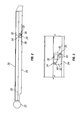
- FIG. 2 is a plan view of an embodiment of a rotor blade
- FIG. 3 is a cross-sectional view of an airflow outlet opening for an embodiment of a rotor blade
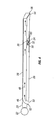
- FIG. 4 is a plan view of another embodiment of a rotor blade.
- FIG. 1 Shown in FIG. 1 is a schematic illustration of a rotary wing aircraft 10 having a main rotor assembly 12.
- the aircraft 10 includes an airframe 14 having an extended tail 16 at which is mounted an anti-torque rotor 18.
- the main rotor assembly 12 includes a plurality of rotor blades 20 located about a rotor shaft 22.
- One or more of the rotor blades 20 includes a control surface such as a trim tab 24 located at a trailing edge 26 of the rotor blade 20.
- control surface shown in FIG. 1 is a trim tab 24, it is to be appreciated that other types of on-blade control surfaces, such as conformal flaps, active flow control devices, unsteady and/or steady blowing devices, flaps, mass displacement devices, etc., are contemplated within the scope of the present disclosure.
- trim tab 24 is shown located at the trailing edge 26 of the rotor blade 20, it is to be appreciated that the control surface may be disposed in other locations, for example, a leading edge 28 of the rotor blade 20.
- the trim tab 24 or other control surface or component is driven by an actuator 30 located at the rotor blade 20.
- the actuator 30 is located in an actuator bay 32 within the rotor blade 20.
- a lower surface flush inlet opening 34 is formed through a skin 36 of the rotor blade 20 into the actuator bay 32.
- a flush outlet opening 38 is formed through the skin 36 into the actuator bay 32.
- the inlet opening 34 and the outlet opening 38 are arranged such that the inlet opening 34 is located at a higher pressure area of the rotor blade 20 than is the outlet opening 38.
- the inlet opening 34 may be located further inboard relative to the rotor shaft 22 and closer to the leading edge 28 of the rotor blade 20, while the outlet opening 38 is located relatively outboard and closer to the trailing edge 26 of the rotor blade 20.
- the actuator bay 32 may include a ramp 40 extending toward the outlet opening 38 to guide airflow through the outlet opening 38.
- the inlet opening 34 and outlet opening 38 are flush to the skin 36 of the rotor blade 20 to reduce the potential for foreign object damage and/or ingestion of debris into the actuator bay 32.
- screens or filters may be utilized at the inlet opening 34 and the outlet opening 36.
- the rotor blade 20 of FIG. 4 includes a spar 46 through which a spar airflow 48 is centrifugally urged from a spar inlet 50 at an inboard end 52 of the rotor blade to a spar outlet 54 at, for example, a blade tip 56.
- the actuator bay 32 is connected to the spar 46 via an inlet passage 58 and an outlet passage 60.
- the high pressure spar airflow 48 as the rotor blade 20 is rotated is urged through the spar 46, and a portion of the spar airflow is diverted through the inlet passage 58 into the actuator bay 32. Thermal energy is transferred from the actuator 30 to the spar airflow 48 thus cooling the actuator 30.
- the diverted spar airflow 48 exits the actuator bay 32 via the outlet passage 60 and rejoins the main spar airflow 48 in the spar 46 until the spar airflow 48 is ejected from the rotor blade 20 at the spar outlet 54.
Landscapes
- Engineering & Computer Science (AREA)
- Mechanical Engineering (AREA)
- Aviation & Aerospace Engineering (AREA)
- Structures Of Non-Positive Displacement Pumps (AREA)
- Turbine Rotor Nozzle Sealing (AREA)
- Motor Or Generator Cooling System (AREA)
Abstract
Description
- This invention was made with US Government support under contract HR0011-10-9-0002 awarded by DOT/FAA William J. Hughes Technical Center. The US Government has certain rights in this invention.
- The subject matter disclosed herein relates to rotors. More specifically, the subject matter disclosed herein relates to cooling of ancillary components of rotor blades.
- Some rotors, for example, some main rotors for helicopters, are adaptive rotors having rotor blades which can change operational state. This is often accomplished by devices in the rotor blades which change the diameter, sweep, chord, tip shape of the blades, and/or other blade parameters. Airfoil sections of adaptive blades may incorporate flaps, slats, and active flow control. Such devices are driven by actuators disposed in the rotor blade. Whether such actuators are electrical, hydraulic, or other types of actuators, a certain amount of cooling is necessary for continued performance of the actuators. Typical cooling systems are complex, heavy, and prone to failure.
- A rotor blade for a rotary wing aircraft includes a component bay located substantially enclosed in the rotor blade and one or more components positioned in the component bay. An airflow inlet is located at the inboard side of the component bay and an airflow outlet is located at the component bay radially outboard of the airflow inlet. The airflow inlet and airflow outlet allow a continuous airflow through the component bay via centrifugal forces of rotation of the rotor blade, the continuous airflow cooling one or more components disposed at the component bay.
- A method of cooling a component of a rotor blade includes rotating a rotor blade about a rotor shaft arid urging air in a component bay out of the component bay through an airflow outlet via centrifugal forces of the rotor blade rotation. An airflow is urged into the component bay via an airflow inlet disposed radially inboard of the airflow outlet and the airflow is flowed past a component disposed in the component bay thereby removing thermal energy from the component.
- These and other advantages and features will become more apparent from the following description taken in conjunction with the drawings.
- The subject matter, which is regarded as the invention, is particularly pointed out and distinctly claimed in the claims at the conclusion of the specification. The foregoing and other features, and advantages of the invention are apparent from the following detailed description taken in conjunction with the accompanying drawings in which:
-
FIG. 1 is schematic illustration of an embodiment of a rotary wing aircraft; -
FIG. 2 is a plan view of an embodiment of a rotor blade; -
FIG. 3 is a cross-sectional view of an airflow outlet opening for an embodiment of a rotor blade; and -
FIG. 4 is a plan view of another embodiment of a rotor blade. - The detailed description explains embodiments of the invention, together with advantages and features, by way of example with reference to the drawings.
- Shown in
FIG. 1 is a schematic illustration of arotary wing aircraft 10 having amain rotor assembly 12. Theaircraft 10 includes anairframe 14 having an extendedtail 16 at which is mounted ananti-torque rotor 18. Although the configuration illustrated is a single main rotor helicopter, it is to be appreciated that other machines such as twin rotor helicopters, turbo-props, and tilt-rotor aircraft, and other aircraft with props or rotors will also benefit from the system of the present disclosure. Themain rotor assembly 12 includes a plurality ofrotor blades 20 located about arotor shaft 22. One or more of therotor blades 20 includes a control surface such as atrim tab 24 located at atrailing edge 26 of therotor blade 20. While the control surface shown inFIG. 1 is atrim tab 24, it is to be appreciated that other types of on-blade control surfaces, such as conformal flaps, active flow control devices, unsteady and/or steady blowing devices, flaps, mass displacement devices, etc., are contemplated within the scope of the present disclosure. Further, while thetrim tab 24 is shown located at thetrailing edge 26 of therotor blade 20, it is to be appreciated that the control surface may be disposed in other locations, for example, a leadingedge 28 of therotor blade 20. - Referring now to
FIG. 2 , thetrim tab 24 or other control surface or component is driven by anactuator 30 located at therotor blade 20. Theactuator 30 is located in anactuator bay 32 within therotor blade 20. A lower surfaceflush inlet opening 34 is formed through askin 36 of therotor blade 20 into theactuator bay 32. Similarly, a flush outlet opening 38 is formed through theskin 36 into theactuator bay 32. The inlet opening 34 and the outlet opening 38 are arranged such that the inlet opening 34 is located at a higher pressure area of therotor blade 20 than is the outlet opening 38. For example, the inlet opening 34 may be located further inboard relative to therotor shaft 22 and closer to the leadingedge 28 of therotor blade 20, while the outlet opening 38 is located relatively outboard and closer to thetrailing edge 26 of therotor blade 20. In some embodiments, as shown inFIG. 3 , theactuator bay 32 may include aramp 40 extending toward the outlet opening 38 to guide airflow through the outlet opening 38. - Referring again to
FIG. 2 , when therotor blade 20 begins to rotate during operation of theaircraft 10, air inside theactuator bay 32 is forced toward anoutboard side 42 of theactuator bay 32 via centrifugal forces, and out of the outlet opening 38. The pressure reduction in the actuator bay 32 due to exit of the air through the outlet opening 38 draws anairflow 44 into theactuator bay 32 which sets up acontinuous airflow 44 through theactuator bay 32 when therotor blade 20 is rotating. Theairflow 44 centrifugally pumped through theactuator bay 32 via rotation of therotor blade 20 provides cooling for theactuator 30 located therein. For example, a 0.25 inch diameter inlet opening 34 and outlet opening 38 are sufficient to cool an approximately 200 watt electric actuator. It is to be appreciated that while airflow is described herein as cooling anactuator 30 located in therotor blade 20, this cooling scheme may be utilized to cool various other components in therotor blade 20 that require cooling, for example, radar components, sensors, or the like. - The inlet opening 34 and outlet opening 38 are flush to the
skin 36 of therotor blade 20 to reduce the potential for foreign object damage and/or ingestion of debris into theactuator bay 32. To further increase foreign object protection, screens or filters may be utilized at the inlet opening 34 and the outlet opening 36. - Another embodiment is shown in
FIG. 4 . Therotor blade 20 ofFIG. 4 includes aspar 46 through which aspar airflow 48 is centrifugally urged from aspar inlet 50 at aninboard end 52 of the rotor blade to aspar outlet 54 at, for example, ablade tip 56. Theactuator bay 32 is connected to thespar 46 via aninlet passage 58 and anoutlet passage 60. The highpressure spar airflow 48 as therotor blade 20 is rotated is urged through thespar 46, and a portion of the spar airflow is diverted through theinlet passage 58 into theactuator bay 32. Thermal energy is transferred from theactuator 30 to thespar airflow 48 thus cooling theactuator 30. The divertedspar airflow 48 exits theactuator bay 32 via theoutlet passage 60 and rejoins themain spar airflow 48 in thespar 46 until thespar airflow 48 is ejected from therotor blade 20 at thespar outlet 54. - While the invention has been described in detail in connection with only a limited number of embodiments, it should be readily understood that the invention is not limited to such disclosed embodiments. Rather, the invention can be modified to incorporate any number of variations, alterations, substitutions or equivalent arrangements not heretofore described, but which are commensurate with the spirit and scope of the invention. Additionally, while various embodiments of the invention have been described, it is to be understood that aspects of the invention may include only some of the described embodiments. Accordingly, the invention is not to be seen as limited by the foregoing description, but is only limited by the scope of the appended claims.
Claims (15)
- A rotor blade for a rotary wing aircraft comprising:a component bay disposed substantially enclosed in the rotor blade;one or more components disposed in the component bay;an airflow inlet disposed at the component bay; andan airflow outlet disposed at the component bay radially outboard of the airflow inlet, the airflow inlet and airflow outlet allowing a continuous airflow through the component bay via centrifugal forces of rotation of the rotor blade, the continuous airflow cooling the one or more components disposed at the component bay.
- The rotor blade of Claim 1, wherein the one or more components are one or more actuators.
- The rotor blade of Claim 1 or 2, wherein at least one of the airflow inlet and the airflow outlet extend through a skin of the rotor blade.
- The rotor blade of Claim 3, wherein the airflow inlet is substantially flush to the skin of the rotor blade.
- The rotor blade of any of the preceding Claims, wherein the component bay includes a ramp to guide the airflow through the airflow outlet.
- The rotor blade of any of the preceding Claims, wherein the airflow inlet is disposed closer to a leading edge of the rotor blade relative to the airflow outlet.
- The rotor blade of any of the preceding Claims, wherein at least one of the airflow inlet and the airflow outlet are in flow communication with an airflow spar extending through the rotor blade.
- The rotor blade of Claim 7, wherein both the airflow inlet and the airflow outlet are in flow communication with the airflow spar.
- The rotor blade of Claim 7 or 8, wherein the airflow spar extends from a spar inlet at an inboard end of the rotor blade to a spar outlet at a tip of the rotor blade.
- A method of cooling a component of a rotor blade comprising:rotating a rotor blade about a rotor shaft;urging air in a component bay out of the component bay through an airflow outlet via centrifugal forces of the rotor blade rotation;urging an airflow into the component bay via an airflow inlet disposed radially inboard of the airflow outlet; andflowing the airflow past a component disposed in the component bay thereby removing thermal energy from the component.
- The method of Claim 10, further comprising flowing the airflow through the airflow outlet extending through a skin of the rotor blade.
- The method of Claim 10 or 11, wherein the airflow inlet extends from a skin of the rotor blade to the component bay.
- The method of any of Claims 10 to 12, further comprising:urging the airflow into an airflow spar of the rotor blade;urging the airflow from the airflow spar into the component bay via the airflow inlet; andurging the airflow from the component bay into the airflow spar via the airflow outlet.
- The method of Claim 13, further comprising urging the airflow into the airflow spar of the rotor blade at an inboard end of the rotor blade.
- The method of Claim 13 or 14, further comprising urging the airflow ejecting the airflow from the airflow spar at a rotor blade tip.
Applications Claiming Priority (1)
| Application Number | Priority Date | Filing Date | Title |
|---|---|---|---|
| US13/272,781 US9090343B2 (en) | 2011-10-13 | 2011-10-13 | Rotor blade component cooling |
Publications (3)
| Publication Number | Publication Date |
|---|---|
| EP2581304A2 true EP2581304A2 (en) | 2013-04-17 |
| EP2581304A3 EP2581304A3 (en) | 2017-11-15 |
| EP2581304B1 EP2581304B1 (en) | 2019-07-24 |
Family
ID=46754891
Family Applications (1)
| Application Number | Title | Priority Date | Filing Date |
|---|---|---|---|
| EP12179925.8A Not-in-force EP2581304B1 (en) | 2011-10-13 | 2012-08-09 | Rotor blade component cooling |
Country Status (2)
| Country | Link |
|---|---|
| US (1) | US9090343B2 (en) |
| EP (1) | EP2581304B1 (en) |
Cited By (1)
| Publication number | Priority date | Publication date | Assignee | Title |
|---|---|---|---|---|
| EP3233630A4 (en) * | 2014-12-19 | 2018-05-30 | Sikorsky Aircraft Corporation | Aircraft rotor blade with reduced stress |
Families Citing this family (8)
| Publication number | Priority date | Publication date | Assignee | Title |
|---|---|---|---|---|
| US9004394B2 (en) * | 2010-09-09 | 2015-04-14 | Groen Brothers Aviation, Inc. | Mission-adaptive rotor blade with circulation control |
| US9637229B2 (en) * | 2011-07-11 | 2017-05-02 | Groen Aeronautics Corporation | Mission-adaptive rotor blade with circulation control |
| US8926272B2 (en) * | 2011-09-07 | 2015-01-06 | Textron Innovations Inc. | System for heat dissipation from an internal actuator in a rotor blade |
| WO2016118226A1 (en) * | 2015-01-22 | 2016-07-28 | Sikorsky Aircraft Corporation | Low noise rotor blade design |
| US20180297692A1 (en) * | 2015-10-17 | 2018-10-18 | Sikorsky Aircraft Corporation | Reduced blade vortex interaction |
| US10371455B2 (en) | 2017-07-11 | 2019-08-06 | Sikorsky Aircraft Corporation | Cooling system for rotor blade actuators |
| CN107416184A (en) * | 2017-08-01 | 2017-12-01 | 西华酷农无人机产业园运营有限公司 | A kind of unmanned plane propeller of high efficiency and heat radiation |
| CN107905961B (en) * | 2017-11-09 | 2019-12-20 | 新疆金风科技股份有限公司 | Heating deicing system and method for blade, blade and wind generating set |
Family Cites Families (39)
| Publication number | Priority date | Publication date | Assignee | Title |
|---|---|---|---|---|
| US2156133A (en) * | 1936-06-16 | 1939-04-25 | Theodore H Troller | Propeller |
| US2476002A (en) * | 1946-01-12 | 1949-07-12 | Edward A Stalker | Rotating wing |
| US2625997A (en) * | 1946-11-01 | 1953-01-20 | Doak Aircraft Company Inc | Helicopter stabilizing device |
| US2638990A (en) * | 1947-04-01 | 1953-05-19 | Autogiro Co Of America | Aircraft sustaining rotor blade with airflow control |
| US2516489A (en) * | 1948-01-16 | 1950-07-25 | Edward A Stalker | Jet propulsive means for aircraft employing boundary layer air or other air with gasturbine power plants |
| CH341717A (en) * | 1956-07-24 | 1959-10-15 | Devlieger Maurice | Method for improving the efficiency of rotary airfoils and airfoils for the implementation of the method |
| US3588273A (en) * | 1969-03-19 | 1971-06-28 | Honeywell Inc | Control apparatus |
| US3795375A (en) * | 1972-05-22 | 1974-03-05 | Kaman Aerospace Corp | System for continuously trimming helicopter rotor blades during flight |
| US3966145A (en) * | 1975-02-28 | 1976-06-29 | The Boeing Company | Structure for cooling helicopter tail rotor gearbox |
| US4045146A (en) * | 1976-05-17 | 1977-08-30 | Avco Corporation | Helicopter rotor blade |
| US4655685A (en) * | 1985-12-16 | 1987-04-07 | United Technologies Corporation | Helicopter main rotor blade having a short span slot near the tip end |
| US5720431A (en) | 1988-08-24 | 1998-02-24 | United Technologies Corporation | Cooled blades for a gas turbine engine |
| US5387083A (en) * | 1992-12-23 | 1995-02-07 | Alliedsignal Inc. | Helicopter servoflap actuator having mechanical stop and oil pump |
| JP2617281B2 (en) * | 1995-03-27 | 1997-06-04 | 株式会社コミュータヘリコプタ先進技術研究所 | Helicopter rotor with flap |
| US5791601A (en) * | 1995-08-22 | 1998-08-11 | Dancila; D. Stefan | Apparatus and method for aerodynamic blowing control using smart materials |
| FR2770826B1 (en) * | 1997-11-07 | 2000-01-07 | Eurocopter France | ROTOR BLADE WITH ADJUSTABLE SHUTTER |
| DE19808196C2 (en) * | 1998-02-27 | 2003-06-05 | Eurocopter Deutschland | Rotor blade for a helicopter |
| JP2907335B1 (en) * | 1998-03-24 | 1999-06-21 | 株式会社コミュータヘリコプタ先進技術研究所 | Flap drive for rotor blades |
| JP3053620B1 (en) * | 1999-02-25 | 2000-06-19 | 株式会社コミュータヘリコプタ先進技術研究所 | Rotary blade flap drive |
| US6203269B1 (en) * | 1999-02-25 | 2001-03-20 | United Technologies Corporation | Centrifugal air flow control |
| JP3004644B1 (en) * | 1999-03-03 | 2000-01-31 | 株式会社コミュータヘリコプタ先進技術研究所 | Rotary blade flap drive |
| US6196796B1 (en) * | 1999-04-22 | 2001-03-06 | Sikorsky Aircraft Corporation | High torque actuation system for an active rotor control system |
| US6513762B2 (en) * | 1999-05-18 | 2003-02-04 | Diversified Technologies, Inc. | Flap actuator system |
| US6231013B1 (en) * | 1999-06-16 | 2001-05-15 | Daimlerchrysler Ag | Airfoil member with a piezoelectrically actuated servo-flap |
| US6322324B1 (en) * | 2000-03-03 | 2001-11-27 | The Boeing Company | Helicopter in-flight rotor tracking system, method, and smart actuator therefor |
| FR2811635B1 (en) * | 2000-07-13 | 2003-01-03 | Eurocopter France | ROTARY WING AIRCRAFT WITH ELECTRIC PITCH CONTROL |
| US6932569B2 (en) * | 2002-05-17 | 2005-08-23 | Sikorsky Aircraft Corporation | Active control of multi-element rotor blade airfoils |
| RU2218477C1 (en) * | 2002-12-30 | 2003-12-10 | ООО "Научно-производственное предприятие "Триумф" | Method to increase rotor blade efficiency of wind-driven electric plant |
| US7217091B2 (en) * | 2004-07-20 | 2007-05-15 | General Electric Company | Methods and apparatus for deicing airfoils or rotor blades |
| JP4931507B2 (en) * | 2005-07-26 | 2012-05-16 | スネクマ | Cooling flow path formed in the wall |
| US7354247B2 (en) * | 2005-10-27 | 2008-04-08 | General Electric Company | Blade for a rotor of a wind energy turbine |
| US8029239B2 (en) * | 2005-11-18 | 2011-10-04 | General Electric Company | Rotor for a wind energy turbine and method for controlling the temperature inside a rotor hub |
| US7637462B2 (en) * | 2006-04-28 | 2009-12-29 | Anadish Kumar Pal | Surface flow diverting and static charging ducted pores on wing or blade tip to reduce wake and BVI noise |
| US7677868B2 (en) | 2006-12-07 | 2010-03-16 | Sikorsky Aircraft Corporation | Self-lubricated actuator for on-blade rotor control |
| US8672627B2 (en) * | 2006-12-14 | 2014-03-18 | Sikorsky Aircraft Corporation | On-blade actuator for helicopter rotor blade control flaps |
| US7785071B1 (en) * | 2007-05-31 | 2010-08-31 | Florida Turbine Technologies, Inc. | Turbine airfoil with spiral trailing edge cooling passages |
| WO2010023278A2 (en) * | 2008-08-29 | 2010-03-04 | Vestas Wind Systems A/S | Control system in wind turbine blades |
| HU227465B1 (en) * | 2009-08-04 | 2011-06-28 | Ferenc Apolczer | Method for constructing rotor blade with upraised boundary layer and rotor blade |
| US8376704B2 (en) * | 2009-11-05 | 2013-02-19 | General Electric Company | Systems and method of assembling an air distribution system for use in a rotor blade of a wind turbine |
-
2011
- 2011-10-13 US US13/272,781 patent/US9090343B2/en active Active
-
2012
- 2012-08-09 EP EP12179925.8A patent/EP2581304B1/en not_active Not-in-force
Non-Patent Citations (1)
| Title |
|---|
| None |
Cited By (1)
| Publication number | Priority date | Publication date | Assignee | Title |
|---|---|---|---|---|
| EP3233630A4 (en) * | 2014-12-19 | 2018-05-30 | Sikorsky Aircraft Corporation | Aircraft rotor blade with reduced stress |
Also Published As
| Publication number | Publication date |
|---|---|
| EP2581304A3 (en) | 2017-11-15 |
| US9090343B2 (en) | 2015-07-28 |
| EP2581304B1 (en) | 2019-07-24 |
| US20130094959A1 (en) | 2013-04-18 |
Similar Documents
| Publication | Publication Date | Title |
|---|---|---|
| US9090343B2 (en) | Rotor blade component cooling | |
| CN107161349B (en) | Propulsion system for aircraft | |
| EP2631175B1 (en) | Adaptive rotor blade | |
| CA3013689C (en) | Aircraft propulsion system with a boundary layer ingestion fan system and method | |
| EP3254962A1 (en) | Electric distributed propulsion anti-torque redundant power and control system | |
| CN109641663B (en) | Deicing module for an aircraft and method for deicing | |
| EP2431275B1 (en) | Rotor blade with integrated passive surface flap | |
| US10415404B2 (en) | Variable-pitch vane | |
| US20130224031A1 (en) | Airfoils for use in rotary machines | |
| EP3074605B1 (en) | Fan blade with segmented fan blade cover | |
| CN107878733A (en) | Translation fan blade for the fan component of aircraft afterbody installation | |
| US11014661B2 (en) | Tip jet orifice for aircraft brown out mitigation | |
| EP3219606B1 (en) | Cross flow fan with exit guide vanes | |
| US10301008B1 (en) | Hinged rotor blade to provide passive variable pitch | |
| CN110001920A (en) | The method of aircraft, wing, fixed-wing, Wing tip device and design interface | |
| EP3504119B1 (en) | Aircraft having an aft engine | |
| EP3031720B1 (en) | Guide vanes for a pusher propeller for rotary wing aircraft | |
| EP3141473B1 (en) | Drag reduction of high speed aircraft with a coaxial-rotor system | |
| EP3103718B1 (en) | Multi-element rotor blade | |
| WO2016118226A1 (en) | Low noise rotor blade design |
Legal Events
| Date | Code | Title | Description |
|---|---|---|---|
| PUAI | Public reference made under article 153(3) epc to a published international application that has entered the european phase |
Free format text: ORIGINAL CODE: 0009012 |
|
| AK | Designated contracting states |
Kind code of ref document: A2 Designated state(s): AL AT BE BG CH CY CZ DE DK EE ES FI FR GB GR HR HU IE IS IT LI LT LU LV MC MK MT NL NO PL PT RO RS SE SI SK SM TR |
|
| AX | Request for extension of the european patent |
Extension state: BA ME |
|
| REG | Reference to a national code |
Ref country code: DE Ref legal event code: R079 Ref document number: 602012062209 Country of ref document: DE Free format text: PREVIOUS MAIN CLASS: B64C0023020000 Ipc: B64C0027473000 |
|
| PUAL | Search report despatched |
Free format text: ORIGINAL CODE: 0009013 |
|
| AK | Designated contracting states |
Kind code of ref document: A3 Designated state(s): AL AT BE BG CH CY CZ DE DK EE ES FI FR GB GR HR HU IE IS IT LI LT LU LV MC MK MT NL NO PL PT RO RS SE SI SK SM TR |
|
| AX | Request for extension of the european patent |
Extension state: BA ME |
|
| RIC1 | Information provided on ipc code assigned before grant |
Ipc: B64C 27/72 20060101ALI20171010BHEP Ipc: B64C 27/473 20060101AFI20171010BHEP |
|
| STAA | Information on the status of an ep patent application or granted ep patent |
Free format text: STATUS: REQUEST FOR EXAMINATION WAS MADE |
|
| 17P | Request for examination filed |
Effective date: 20180514 |
|
| RBV | Designated contracting states (corrected) |
Designated state(s): AL AT BE BG CH CY CZ DE DK EE ES FI FR GB GR HR HU IE IS IT LI LT LU LV MC MK MT NL NO PL PT RO RS SE SI SK SM TR |
|
| GRAP | Despatch of communication of intention to grant a patent |
Free format text: ORIGINAL CODE: EPIDOSNIGR1 |
|
| STAA | Information on the status of an ep patent application or granted ep patent |
Free format text: STATUS: GRANT OF PATENT IS INTENDED |
|
| INTG | Intention to grant announced |
Effective date: 20190207 |
|
| GRAS | Grant fee paid |
Free format text: ORIGINAL CODE: EPIDOSNIGR3 |
|
| GRAA | (expected) grant |
Free format text: ORIGINAL CODE: 0009210 |
|
| STAA | Information on the status of an ep patent application or granted ep patent |
Free format text: STATUS: THE PATENT HAS BEEN GRANTED |
|
| AK | Designated contracting states |
Kind code of ref document: B1 Designated state(s): AL AT BE BG CH CY CZ DE DK EE ES FI FR GB GR HR HU IE IS IT LI LT LU LV MC MK MT NL NO PL PT RO RS SE SI SK SM TR |
|
| REG | Reference to a national code |
Ref country code: GB Ref legal event code: FG4D |
|
| REG | Reference to a national code |
Ref country code: CH Ref legal event code: EP |
|
| REG | Reference to a national code |
Ref country code: DE Ref legal event code: R096 Ref document number: 602012062209 Country of ref document: DE |
|
| REG | Reference to a national code |
Ref country code: AT Ref legal event code: REF Ref document number: 1157869 Country of ref document: AT Kind code of ref document: T Effective date: 20190815 |
|
| REG | Reference to a national code |
Ref country code: IE Ref legal event code: FG4D |
|
| PGFP | Annual fee paid to national office [announced via postgrant information from national office to epo] |
Ref country code: FR Payment date: 20190826 Year of fee payment: 8 Ref country code: DE Payment date: 20190828 Year of fee payment: 8 |
|
| REG | Reference to a national code |
Ref country code: NL Ref legal event code: MP Effective date: 20190724 |
|
| REG | Reference to a national code |
Ref country code: LT Ref legal event code: MG4D |
|
| PGFP | Annual fee paid to national office [announced via postgrant information from national office to epo] |
Ref country code: GB Payment date: 20190827 Year of fee payment: 8 |
|
| REG | Reference to a national code |
Ref country code: AT Ref legal event code: MK05 Ref document number: 1157869 Country of ref document: AT Kind code of ref document: T Effective date: 20190724 |
|
| PG25 | Lapsed in a contracting state [announced via postgrant information from national office to epo] |
Ref country code: NL Free format text: LAPSE BECAUSE OF FAILURE TO SUBMIT A TRANSLATION OF THE DESCRIPTION OR TO PAY THE FEE WITHIN THE PRESCRIBED TIME-LIMIT Effective date: 20190724 Ref country code: AT Free format text: LAPSE BECAUSE OF FAILURE TO SUBMIT A TRANSLATION OF THE DESCRIPTION OR TO PAY THE FEE WITHIN THE PRESCRIBED TIME-LIMIT Effective date: 20190724 Ref country code: SE Free format text: LAPSE BECAUSE OF FAILURE TO SUBMIT A TRANSLATION OF THE DESCRIPTION OR TO PAY THE FEE WITHIN THE PRESCRIBED TIME-LIMIT Effective date: 20190724 Ref country code: BG Free format text: LAPSE BECAUSE OF FAILURE TO SUBMIT A TRANSLATION OF THE DESCRIPTION OR TO PAY THE FEE WITHIN THE PRESCRIBED TIME-LIMIT Effective date: 20191024 Ref country code: PT Free format text: LAPSE BECAUSE OF FAILURE TO SUBMIT A TRANSLATION OF THE DESCRIPTION OR TO PAY THE FEE WITHIN THE PRESCRIBED TIME-LIMIT Effective date: 20191125 Ref country code: HR Free format text: LAPSE BECAUSE OF FAILURE TO SUBMIT A TRANSLATION OF THE DESCRIPTION OR TO PAY THE FEE WITHIN THE PRESCRIBED TIME-LIMIT Effective date: 20190724 Ref country code: LT Free format text: LAPSE BECAUSE OF FAILURE TO SUBMIT A TRANSLATION OF THE DESCRIPTION OR TO PAY THE FEE WITHIN THE PRESCRIBED TIME-LIMIT Effective date: 20190724 Ref country code: NO Free format text: LAPSE BECAUSE OF FAILURE TO SUBMIT A TRANSLATION OF THE DESCRIPTION OR TO PAY THE FEE WITHIN THE PRESCRIBED TIME-LIMIT Effective date: 20191024 Ref country code: FI Free format text: LAPSE BECAUSE OF FAILURE TO SUBMIT A TRANSLATION OF THE DESCRIPTION OR TO PAY THE FEE WITHIN THE PRESCRIBED TIME-LIMIT Effective date: 20190724 |
|
| PG25 | Lapsed in a contracting state [announced via postgrant information from national office to epo] |
Ref country code: IS Free format text: LAPSE BECAUSE OF FAILURE TO SUBMIT A TRANSLATION OF THE DESCRIPTION OR TO PAY THE FEE WITHIN THE PRESCRIBED TIME-LIMIT Effective date: 20191124 Ref country code: ES Free format text: LAPSE BECAUSE OF FAILURE TO SUBMIT A TRANSLATION OF THE DESCRIPTION OR TO PAY THE FEE WITHIN THE PRESCRIBED TIME-LIMIT Effective date: 20190724 Ref country code: RS Free format text: LAPSE BECAUSE OF FAILURE TO SUBMIT A TRANSLATION OF THE DESCRIPTION OR TO PAY THE FEE WITHIN THE PRESCRIBED TIME-LIMIT Effective date: 20190724 Ref country code: GR Free format text: LAPSE BECAUSE OF FAILURE TO SUBMIT A TRANSLATION OF THE DESCRIPTION OR TO PAY THE FEE WITHIN THE PRESCRIBED TIME-LIMIT Effective date: 20191025 Ref country code: AL Free format text: LAPSE BECAUSE OF FAILURE TO SUBMIT A TRANSLATION OF THE DESCRIPTION OR TO PAY THE FEE WITHIN THE PRESCRIBED TIME-LIMIT Effective date: 20190724 Ref country code: LV Free format text: LAPSE BECAUSE OF FAILURE TO SUBMIT A TRANSLATION OF THE DESCRIPTION OR TO PAY THE FEE WITHIN THE PRESCRIBED TIME-LIMIT Effective date: 20190724 |
|
| PG25 | Lapsed in a contracting state [announced via postgrant information from national office to epo] |
Ref country code: TR Free format text: LAPSE BECAUSE OF FAILURE TO SUBMIT A TRANSLATION OF THE DESCRIPTION OR TO PAY THE FEE WITHIN THE PRESCRIBED TIME-LIMIT Effective date: 20190724 |
|
| PG25 | Lapsed in a contracting state [announced via postgrant information from national office to epo] |
Ref country code: DK Free format text: LAPSE BECAUSE OF FAILURE TO SUBMIT A TRANSLATION OF THE DESCRIPTION OR TO PAY THE FEE WITHIN THE PRESCRIBED TIME-LIMIT Effective date: 20190724 Ref country code: IT Free format text: LAPSE BECAUSE OF FAILURE TO SUBMIT A TRANSLATION OF THE DESCRIPTION OR TO PAY THE FEE WITHIN THE PRESCRIBED TIME-LIMIT Effective date: 20190724 Ref country code: EE Free format text: LAPSE BECAUSE OF FAILURE TO SUBMIT A TRANSLATION OF THE DESCRIPTION OR TO PAY THE FEE WITHIN THE PRESCRIBED TIME-LIMIT Effective date: 20190724 Ref country code: RO Free format text: LAPSE BECAUSE OF FAILURE TO SUBMIT A TRANSLATION OF THE DESCRIPTION OR TO PAY THE FEE WITHIN THE PRESCRIBED TIME-LIMIT Effective date: 20190724 Ref country code: PL Free format text: LAPSE BECAUSE OF FAILURE TO SUBMIT A TRANSLATION OF THE DESCRIPTION OR TO PAY THE FEE WITHIN THE PRESCRIBED TIME-LIMIT Effective date: 20190724 |
|
| PG25 | Lapsed in a contracting state [announced via postgrant information from national office to epo] |
Ref country code: LU Free format text: LAPSE BECAUSE OF NON-PAYMENT OF DUE FEES Effective date: 20190809 Ref country code: IS Free format text: LAPSE BECAUSE OF FAILURE TO SUBMIT A TRANSLATION OF THE DESCRIPTION OR TO PAY THE FEE WITHIN THE PRESCRIBED TIME-LIMIT Effective date: 20200224 Ref country code: SK Free format text: LAPSE BECAUSE OF FAILURE TO SUBMIT A TRANSLATION OF THE DESCRIPTION OR TO PAY THE FEE WITHIN THE PRESCRIBED TIME-LIMIT Effective date: 20190724 Ref country code: MC Free format text: LAPSE BECAUSE OF FAILURE TO SUBMIT A TRANSLATION OF THE DESCRIPTION OR TO PAY THE FEE WITHIN THE PRESCRIBED TIME-LIMIT Effective date: 20190724 Ref country code: CH Free format text: LAPSE BECAUSE OF NON-PAYMENT OF DUE FEES Effective date: 20190831 Ref country code: CZ Free format text: LAPSE BECAUSE OF FAILURE TO SUBMIT A TRANSLATION OF THE DESCRIPTION OR TO PAY THE FEE WITHIN THE PRESCRIBED TIME-LIMIT Effective date: 20190724 Ref country code: LI Free format text: LAPSE BECAUSE OF NON-PAYMENT OF DUE FEES Effective date: 20190831 Ref country code: SM Free format text: LAPSE BECAUSE OF FAILURE TO SUBMIT A TRANSLATION OF THE DESCRIPTION OR TO PAY THE FEE WITHIN THE PRESCRIBED TIME-LIMIT Effective date: 20190724 |
|
| REG | Reference to a national code |
Ref country code: BE Ref legal event code: MM Effective date: 20190831 |
|
| REG | Reference to a national code |
Ref country code: DE Ref legal event code: R097 Ref document number: 602012062209 Country of ref document: DE |
|
| PLBE | No opposition filed within time limit |
Free format text: ORIGINAL CODE: 0009261 |
|
| STAA | Information on the status of an ep patent application or granted ep patent |
Free format text: STATUS: NO OPPOSITION FILED WITHIN TIME LIMIT |
|
| PG2D | Information on lapse in contracting state deleted |
Ref country code: IS |
|
| PG25 | Lapsed in a contracting state [announced via postgrant information from national office to epo] |
Ref country code: IE Free format text: LAPSE BECAUSE OF NON-PAYMENT OF DUE FEES Effective date: 20190809 |
|
| 26N | No opposition filed |
Effective date: 20200603 |
|
| PG25 | Lapsed in a contracting state [announced via postgrant information from national office to epo] |
Ref country code: BE Free format text: LAPSE BECAUSE OF NON-PAYMENT OF DUE FEES Effective date: 20190831 Ref country code: SI Free format text: LAPSE BECAUSE OF FAILURE TO SUBMIT A TRANSLATION OF THE DESCRIPTION OR TO PAY THE FEE WITHIN THE PRESCRIBED TIME-LIMIT Effective date: 20190724 |
|
| REG | Reference to a national code |
Ref country code: DE Ref legal event code: R119 Ref document number: 602012062209 Country of ref document: DE |
|
| GBPC | Gb: european patent ceased through non-payment of renewal fee |
Effective date: 20200809 |
|
| PG25 | Lapsed in a contracting state [announced via postgrant information from national office to epo] |
Ref country code: CY Free format text: LAPSE BECAUSE OF FAILURE TO SUBMIT A TRANSLATION OF THE DESCRIPTION OR TO PAY THE FEE WITHIN THE PRESCRIBED TIME-LIMIT Effective date: 20190724 |
|
| PG25 | Lapsed in a contracting state [announced via postgrant information from national office to epo] |
Ref country code: HU Free format text: LAPSE BECAUSE OF FAILURE TO SUBMIT A TRANSLATION OF THE DESCRIPTION OR TO PAY THE FEE WITHIN THE PRESCRIBED TIME-LIMIT; INVALID AB INITIO Effective date: 20120809 Ref country code: MT Free format text: LAPSE BECAUSE OF FAILURE TO SUBMIT A TRANSLATION OF THE DESCRIPTION OR TO PAY THE FEE WITHIN THE PRESCRIBED TIME-LIMIT Effective date: 20190724 Ref country code: DE Free format text: LAPSE BECAUSE OF NON-PAYMENT OF DUE FEES Effective date: 20210302 Ref country code: FR Free format text: LAPSE BECAUSE OF NON-PAYMENT OF DUE FEES Effective date: 20200831 |
|
| PG25 | Lapsed in a contracting state [announced via postgrant information from national office to epo] |
Ref country code: GB Free format text: LAPSE BECAUSE OF NON-PAYMENT OF DUE FEES Effective date: 20200809 |
|
| PG25 | Lapsed in a contracting state [announced via postgrant information from national office to epo] |
Ref country code: MK Free format text: LAPSE BECAUSE OF FAILURE TO SUBMIT A TRANSLATION OF THE DESCRIPTION OR TO PAY THE FEE WITHIN THE PRESCRIBED TIME-LIMIT Effective date: 20190724 |
|
| P01 | Opt-out of the competence of the unified patent court (upc) registered |
Effective date: 20230520 |