EP2581283A1 - Hybrid car control device, hybrid car control method, and hybrid car - Google Patents
Hybrid car control device, hybrid car control method, and hybrid car Download PDFInfo
- Publication number
- EP2581283A1 EP2581283A1 EP10852876.1A EP10852876A EP2581283A1 EP 2581283 A1 EP2581283 A1 EP 2581283A1 EP 10852876 A EP10852876 A EP 10852876A EP 2581283 A1 EP2581283 A1 EP 2581283A1
- Authority
- EP
- European Patent Office
- Prior art keywords
- state
- output power
- internal combustion
- combustion engine
- hybrid vehicle
- Prior art date
- Legal status (The legal status is an assumption and is not a legal conclusion. Google has not performed a legal analysis and makes no representation as to the accuracy of the status listed.)
- Granted
Links
- 238000000034 method Methods 0.000 title claims description 14
- 238000002485 combustion reaction Methods 0.000 claims description 42
- 239000002826 coolant Substances 0.000 claims description 11
- 238000010438 heat treatment Methods 0.000 claims 1
- 230000008569 process Effects 0.000 description 8
- 239000000446 fuel Substances 0.000 description 7
- 239000003054 catalyst Substances 0.000 description 6
- 230000009467 reduction Effects 0.000 description 6
- 238000010586 diagram Methods 0.000 description 4
- 230000007935 neutral effect Effects 0.000 description 2
- 230000001172 regenerating effect Effects 0.000 description 2
- 230000001133 acceleration Effects 0.000 description 1
- 239000003990 capacitor Substances 0.000 description 1
- 238000004140 cleaning Methods 0.000 description 1
- 230000003247 decreasing effect Effects 0.000 description 1
- 238000001514 detection method Methods 0.000 description 1
- 230000000694 effects Effects 0.000 description 1
- 230000005669 field effect Effects 0.000 description 1
- 229910044991 metal oxide Inorganic materials 0.000 description 1
- 150000004706 metal oxides Chemical class 0.000 description 1
- 239000000203 mixture Substances 0.000 description 1
- 238000012986 modification Methods 0.000 description 1
- 230000004048 modification Effects 0.000 description 1
- 238000010248 power generation Methods 0.000 description 1
- 230000004044 response Effects 0.000 description 1
- 239000004065 semiconductor Substances 0.000 description 1
- 238000004088 simulation Methods 0.000 description 1
Images


Classifications
-
- B—PERFORMING OPERATIONS; TRANSPORTING
- B60—VEHICLES IN GENERAL
- B60W—CONJOINT CONTROL OF VEHICLE SUB-UNITS OF DIFFERENT TYPE OR DIFFERENT FUNCTION; CONTROL SYSTEMS SPECIALLY ADAPTED FOR HYBRID VEHICLES; ROAD VEHICLE DRIVE CONTROL SYSTEMS FOR PURPOSES NOT RELATED TO THE CONTROL OF A PARTICULAR SUB-UNIT
- B60W20/00—Control systems specially adapted for hybrid vehicles
- B60W20/10—Controlling the power contribution of each of the prime movers to meet required power demand
- B60W20/15—Control strategies specially adapted for achieving a particular effect
-
- B—PERFORMING OPERATIONS; TRANSPORTING
- B60—VEHICLES IN GENERAL
- B60K—ARRANGEMENT OR MOUNTING OF PROPULSION UNITS OR OF TRANSMISSIONS IN VEHICLES; ARRANGEMENT OR MOUNTING OF PLURAL DIVERSE PRIME-MOVERS IN VEHICLES; AUXILIARY DRIVES FOR VEHICLES; INSTRUMENTATION OR DASHBOARDS FOR VEHICLES; ARRANGEMENTS IN CONNECTION WITH COOLING, AIR INTAKE, GAS EXHAUST OR FUEL SUPPLY OF PROPULSION UNITS IN VEHICLES
- B60K6/00—Arrangement or mounting of plural diverse prime-movers for mutual or common propulsion, e.g. hybrid propulsion systems comprising electric motors and internal combustion engines ; Control systems therefor, i.e. systems controlling two or more prime movers, or controlling one of these prime movers and any of the transmission, drive or drive units Informative references: mechanical gearings with secondary electric drive F16H3/72; arrangements for handling mechanical energy structurally associated with the dynamo-electric machine H02K7/00; machines comprising structurally interrelated motor and generator parts H02K51/00; dynamo-electric machines not otherwise provided for in H02K see H02K99/00
- B60K6/20—Arrangement or mounting of plural diverse prime-movers for mutual or common propulsion, e.g. hybrid propulsion systems comprising electric motors and internal combustion engines ; Control systems therefor, i.e. systems controlling two or more prime movers, or controlling one of these prime movers and any of the transmission, drive or drive units Informative references: mechanical gearings with secondary electric drive F16H3/72; arrangements for handling mechanical energy structurally associated with the dynamo-electric machine H02K7/00; machines comprising structurally interrelated motor and generator parts H02K51/00; dynamo-electric machines not otherwise provided for in H02K see H02K99/00 the prime-movers consisting of electric motors and internal combustion engines, e.g. HEVs
- B60K6/42—Arrangement or mounting of plural diverse prime-movers for mutual or common propulsion, e.g. hybrid propulsion systems comprising electric motors and internal combustion engines ; Control systems therefor, i.e. systems controlling two or more prime movers, or controlling one of these prime movers and any of the transmission, drive or drive units Informative references: mechanical gearings with secondary electric drive F16H3/72; arrangements for handling mechanical energy structurally associated with the dynamo-electric machine H02K7/00; machines comprising structurally interrelated motor and generator parts H02K51/00; dynamo-electric machines not otherwise provided for in H02K see H02K99/00 the prime-movers consisting of electric motors and internal combustion engines, e.g. HEVs characterised by the architecture of the hybrid electric vehicle
- B60K6/44—Series-parallel type
- B60K6/445—Differential gearing distribution type
-
- B—PERFORMING OPERATIONS; TRANSPORTING
- B60—VEHICLES IN GENERAL
- B60K—ARRANGEMENT OR MOUNTING OF PROPULSION UNITS OR OF TRANSMISSIONS IN VEHICLES; ARRANGEMENT OR MOUNTING OF PLURAL DIVERSE PRIME-MOVERS IN VEHICLES; AUXILIARY DRIVES FOR VEHICLES; INSTRUMENTATION OR DASHBOARDS FOR VEHICLES; ARRANGEMENTS IN CONNECTION WITH COOLING, AIR INTAKE, GAS EXHAUST OR FUEL SUPPLY OF PROPULSION UNITS IN VEHICLES
- B60K6/00—Arrangement or mounting of plural diverse prime-movers for mutual or common propulsion, e.g. hybrid propulsion systems comprising electric motors and internal combustion engines ; Control systems therefor, i.e. systems controlling two or more prime movers, or controlling one of these prime movers and any of the transmission, drive or drive units Informative references: mechanical gearings with secondary electric drive F16H3/72; arrangements for handling mechanical energy structurally associated with the dynamo-electric machine H02K7/00; machines comprising structurally interrelated motor and generator parts H02K51/00; dynamo-electric machines not otherwise provided for in H02K see H02K99/00
- B60K6/20—Arrangement or mounting of plural diverse prime-movers for mutual or common propulsion, e.g. hybrid propulsion systems comprising electric motors and internal combustion engines ; Control systems therefor, i.e. systems controlling two or more prime movers, or controlling one of these prime movers and any of the transmission, drive or drive units Informative references: mechanical gearings with secondary electric drive F16H3/72; arrangements for handling mechanical energy structurally associated with the dynamo-electric machine H02K7/00; machines comprising structurally interrelated motor and generator parts H02K51/00; dynamo-electric machines not otherwise provided for in H02K see H02K99/00 the prime-movers consisting of electric motors and internal combustion engines, e.g. HEVs
- B60K6/42—Arrangement or mounting of plural diverse prime-movers for mutual or common propulsion, e.g. hybrid propulsion systems comprising electric motors and internal combustion engines ; Control systems therefor, i.e. systems controlling two or more prime movers, or controlling one of these prime movers and any of the transmission, drive or drive units Informative references: mechanical gearings with secondary electric drive F16H3/72; arrangements for handling mechanical energy structurally associated with the dynamo-electric machine H02K7/00; machines comprising structurally interrelated motor and generator parts H02K51/00; dynamo-electric machines not otherwise provided for in H02K see H02K99/00 the prime-movers consisting of electric motors and internal combustion engines, e.g. HEVs characterised by the architecture of the hybrid electric vehicle
- B60K6/44—Series-parallel type
- B60K6/442—Series-parallel switching type
-
- B—PERFORMING OPERATIONS; TRANSPORTING
- B60—VEHICLES IN GENERAL
- B60W—CONJOINT CONTROL OF VEHICLE SUB-UNITS OF DIFFERENT TYPE OR DIFFERENT FUNCTION; CONTROL SYSTEMS SPECIALLY ADAPTED FOR HYBRID VEHICLES; ROAD VEHICLE DRIVE CONTROL SYSTEMS FOR PURPOSES NOT RELATED TO THE CONTROL OF A PARTICULAR SUB-UNIT
- B60W10/00—Conjoint control of vehicle sub-units of different type or different function
- B60W10/04—Conjoint control of vehicle sub-units of different type or different function including control of propulsion units
- B60W10/06—Conjoint control of vehicle sub-units of different type or different function including control of propulsion units including control of combustion engines
-
- B—PERFORMING OPERATIONS; TRANSPORTING
- B60—VEHICLES IN GENERAL
- B60W—CONJOINT CONTROL OF VEHICLE SUB-UNITS OF DIFFERENT TYPE OR DIFFERENT FUNCTION; CONTROL SYSTEMS SPECIALLY ADAPTED FOR HYBRID VEHICLES; ROAD VEHICLE DRIVE CONTROL SYSTEMS FOR PURPOSES NOT RELATED TO THE CONTROL OF A PARTICULAR SUB-UNIT
- B60W10/00—Conjoint control of vehicle sub-units of different type or different function
- B60W10/04—Conjoint control of vehicle sub-units of different type or different function including control of propulsion units
- B60W10/08—Conjoint control of vehicle sub-units of different type or different function including control of propulsion units including control of electric propulsion units, e.g. motors or generators
-
- B—PERFORMING OPERATIONS; TRANSPORTING
- B60—VEHICLES IN GENERAL
- B60W—CONJOINT CONTROL OF VEHICLE SUB-UNITS OF DIFFERENT TYPE OR DIFFERENT FUNCTION; CONTROL SYSTEMS SPECIALLY ADAPTED FOR HYBRID VEHICLES; ROAD VEHICLE DRIVE CONTROL SYSTEMS FOR PURPOSES NOT RELATED TO THE CONTROL OF A PARTICULAR SUB-UNIT
- B60W10/00—Conjoint control of vehicle sub-units of different type or different function
- B60W10/24—Conjoint control of vehicle sub-units of different type or different function including control of energy storage means
- B60W10/26—Conjoint control of vehicle sub-units of different type or different function including control of energy storage means for electrical energy, e.g. batteries or capacitors
-
- B—PERFORMING OPERATIONS; TRANSPORTING
- B60—VEHICLES IN GENERAL
- B60W—CONJOINT CONTROL OF VEHICLE SUB-UNITS OF DIFFERENT TYPE OR DIFFERENT FUNCTION; CONTROL SYSTEMS SPECIALLY ADAPTED FOR HYBRID VEHICLES; ROAD VEHICLE DRIVE CONTROL SYSTEMS FOR PURPOSES NOT RELATED TO THE CONTROL OF A PARTICULAR SUB-UNIT
- B60W10/00—Conjoint control of vehicle sub-units of different type or different function
- B60W10/30—Conjoint control of vehicle sub-units of different type or different function including control of auxiliary equipment, e.g. air-conditioning compressors or oil pumps
-
- B—PERFORMING OPERATIONS; TRANSPORTING
- B60—VEHICLES IN GENERAL
- B60W—CONJOINT CONTROL OF VEHICLE SUB-UNITS OF DIFFERENT TYPE OR DIFFERENT FUNCTION; CONTROL SYSTEMS SPECIALLY ADAPTED FOR HYBRID VEHICLES; ROAD VEHICLE DRIVE CONTROL SYSTEMS FOR PURPOSES NOT RELATED TO THE CONTROL OF A PARTICULAR SUB-UNIT
- B60W20/00—Control systems specially adapted for hybrid vehicles
- B60W20/10—Controlling the power contribution of each of the prime movers to meet required power demand
- B60W20/13—Controlling the power contribution of each of the prime movers to meet required power demand in order to stay within battery power input or output limits; in order to prevent overcharging or battery depletion
-
- B—PERFORMING OPERATIONS; TRANSPORTING
- B60—VEHICLES IN GENERAL
- B60W—CONJOINT CONTROL OF VEHICLE SUB-UNITS OF DIFFERENT TYPE OR DIFFERENT FUNCTION; CONTROL SYSTEMS SPECIALLY ADAPTED FOR HYBRID VEHICLES; ROAD VEHICLE DRIVE CONTROL SYSTEMS FOR PURPOSES NOT RELATED TO THE CONTROL OF A PARTICULAR SUB-UNIT
- B60W30/00—Purposes of road vehicle drive control systems not related to the control of a particular sub-unit, e.g. of systems using conjoint control of vehicle sub-units
- B60W30/18—Propelling the vehicle
- B60W30/188—Controlling power parameters of the driveline, e.g. determining the required power
-
- B—PERFORMING OPERATIONS; TRANSPORTING
- B60—VEHICLES IN GENERAL
- B60W—CONJOINT CONTROL OF VEHICLE SUB-UNITS OF DIFFERENT TYPE OR DIFFERENT FUNCTION; CONTROL SYSTEMS SPECIALLY ADAPTED FOR HYBRID VEHICLES; ROAD VEHICLE DRIVE CONTROL SYSTEMS FOR PURPOSES NOT RELATED TO THE CONTROL OF A PARTICULAR SUB-UNIT
- B60W50/00—Details of control systems for road vehicle drive control not related to the control of a particular sub-unit, e.g. process diagnostic or vehicle driver interfaces
- B60W50/06—Improving the dynamic response of the control system, e.g. improving the speed of regulation or avoiding hunting or overshoot
-
- B—PERFORMING OPERATIONS; TRANSPORTING
- B60—VEHICLES IN GENERAL
- B60W—CONJOINT CONTROL OF VEHICLE SUB-UNITS OF DIFFERENT TYPE OR DIFFERENT FUNCTION; CONTROL SYSTEMS SPECIALLY ADAPTED FOR HYBRID VEHICLES; ROAD VEHICLE DRIVE CONTROL SYSTEMS FOR PURPOSES NOT RELATED TO THE CONTROL OF A PARTICULAR SUB-UNIT
- B60W2510/00—Input parameters relating to a particular sub-units
- B60W2510/06—Combustion engines, Gas turbines
- B60W2510/0676—Engine temperature
-
- B—PERFORMING OPERATIONS; TRANSPORTING
- B60—VEHICLES IN GENERAL
- B60W—CONJOINT CONTROL OF VEHICLE SUB-UNITS OF DIFFERENT TYPE OR DIFFERENT FUNCTION; CONTROL SYSTEMS SPECIALLY ADAPTED FOR HYBRID VEHICLES; ROAD VEHICLE DRIVE CONTROL SYSTEMS FOR PURPOSES NOT RELATED TO THE CONTROL OF A PARTICULAR SUB-UNIT
- B60W2510/00—Input parameters relating to a particular sub-units
- B60W2510/24—Energy storage means
- B60W2510/242—Energy storage means for electrical energy
- B60W2510/244—Charge state
-
- B—PERFORMING OPERATIONS; TRANSPORTING
- B60—VEHICLES IN GENERAL
- B60W—CONJOINT CONTROL OF VEHICLE SUB-UNITS OF DIFFERENT TYPE OR DIFFERENT FUNCTION; CONTROL SYSTEMS SPECIALLY ADAPTED FOR HYBRID VEHICLES; ROAD VEHICLE DRIVE CONTROL SYSTEMS FOR PURPOSES NOT RELATED TO THE CONTROL OF A PARTICULAR SUB-UNIT
- B60W2510/00—Input parameters relating to a particular sub-units
- B60W2510/24—Energy storage means
- B60W2510/242—Energy storage means for electrical energy
- B60W2510/246—Temperature
-
- B—PERFORMING OPERATIONS; TRANSPORTING
- B60—VEHICLES IN GENERAL
- B60W—CONJOINT CONTROL OF VEHICLE SUB-UNITS OF DIFFERENT TYPE OR DIFFERENT FUNCTION; CONTROL SYSTEMS SPECIALLY ADAPTED FOR HYBRID VEHICLES; ROAD VEHICLE DRIVE CONTROL SYSTEMS FOR PURPOSES NOT RELATED TO THE CONTROL OF A PARTICULAR SUB-UNIT
- B60W2710/00—Output or target parameters relating to a particular sub-units
- B60W2710/06—Combustion engines, Gas turbines
- B60W2710/0677—Engine power
-
- Y—GENERAL TAGGING OF NEW TECHNOLOGICAL DEVELOPMENTS; GENERAL TAGGING OF CROSS-SECTIONAL TECHNOLOGIES SPANNING OVER SEVERAL SECTIONS OF THE IPC; TECHNICAL SUBJECTS COVERED BY FORMER USPC CROSS-REFERENCE ART COLLECTIONS [XRACs] AND DIGESTS
- Y02—TECHNOLOGIES OR APPLICATIONS FOR MITIGATION OR ADAPTATION AGAINST CLIMATE CHANGE
- Y02T—CLIMATE CHANGE MITIGATION TECHNOLOGIES RELATED TO TRANSPORTATION
- Y02T10/00—Road transport of goods or passengers
- Y02T10/10—Internal combustion engine [ICE] based vehicles
- Y02T10/40—Engine management systems
-
- Y—GENERAL TAGGING OF NEW TECHNOLOGICAL DEVELOPMENTS; GENERAL TAGGING OF CROSS-SECTIONAL TECHNOLOGIES SPANNING OVER SEVERAL SECTIONS OF THE IPC; TECHNICAL SUBJECTS COVERED BY FORMER USPC CROSS-REFERENCE ART COLLECTIONS [XRACs] AND DIGESTS
- Y02—TECHNOLOGIES OR APPLICATIONS FOR MITIGATION OR ADAPTATION AGAINST CLIMATE CHANGE
- Y02T—CLIMATE CHANGE MITIGATION TECHNOLOGIES RELATED TO TRANSPORTATION
- Y02T10/00—Road transport of goods or passengers
- Y02T10/60—Other road transportation technologies with climate change mitigation effect
- Y02T10/62—Hybrid vehicles
-
- Y—GENERAL TAGGING OF NEW TECHNOLOGICAL DEVELOPMENTS; GENERAL TAGGING OF CROSS-SECTIONAL TECHNOLOGIES SPANNING OVER SEVERAL SECTIONS OF THE IPC; TECHNICAL SUBJECTS COVERED BY FORMER USPC CROSS-REFERENCE ART COLLECTIONS [XRACs] AND DIGESTS
- Y10—TECHNICAL SUBJECTS COVERED BY FORMER USPC
- Y10S—TECHNICAL SUBJECTS COVERED BY FORMER USPC CROSS-REFERENCE ART COLLECTIONS [XRACs] AND DIGESTS
- Y10S903/00—Hybrid electric vehicles, HEVS
- Y10S903/902—Prime movers comprising electrical and internal combustion motors
- Y10S903/903—Prime movers comprising electrical and internal combustion motors having energy storing means, e.g. battery, capacitor
Definitions
- the present invention relates to a control device for a hybrid vehicle, a control method for a hybrid vehicle, and a hybrid vehicle, and more particularly to a technique of controlling a hybrid vehicle so that an internal combustion engine mounted thereon is stopped.
- Hybrid vehicles incorporating an electric motor as a driving source in addition to an internal combustion engine are known.
- the internal combustion engine when the vehicle speed is low, for example, the internal combustion engine is stopped and only the electric motor can be used for running.
- the internal combustion engine is started when the accelerator position becomes larger, for example. It is desired to drive the internal combustion engine with high thermal efficiency.
- Japanese Patent Laying-Open No. 2006-94626 discloses in paragraph 0034 and the like that an engine is driven when requested power that is set based on the accelerator position is equal to or greater than a threshold value.
- Japanese Patent Laying-Open No. 2006-94626 also discloses in paragraph 0036 and the like that the engine is operated based on the requested power that is reset to increase by a compatible value which is set to increase overall efficiency.
- requested power is set to increase after an internal combustion engine has been started, it is difficult for the requested power to become smaller than a threshold value used to determine whether or not to stop the internal combustion engine. This may lower the frequency with which the internal combustion engine is stopped and only an electric motor is used for the running of a hybrid vehicle.
- An object of the present invention is to increase the frequency with which an internal combustion engine is stopped.
- a control device for a hybrid vehicle which includes an internal combustion engine, an electric motor, and a power storage device that stores electric power to be supplied to the electric motor, and which runs using at least one of the internal combustion engine and the electric motor includes means for setting first output power in accordance with operation by a driver, means for setting second output power greater than the first output power, means for controlling the internal combustion engine to drive in accordance with the second output power, and stop means for stopping the internal combustion engine when the first output power is equal to or smaller than a predetermined threshold value.
- a control method for a hybrid vehicle which includes an internal combustion engine, an electric motor, and a power storage device that stores electric power to be supplied to the electric motor, and which runs using at least one of the internal combustion engine and the electric motor includes the steps of setting first output power in accordance with operation by a driver, setting second output power greater than the first output power, controlling the internal combustion engine to drive in accordance with the second output power, and stopping the internal combustion engine when the first output power is equal to or smaller than a predetermined threshold value.
- a hybrid vehicle which includes an internal combustion engine, an electric motor, and a power storage device that stores electric power to be supplied to the electric motor, and which runs using at least one of the internal combustion engine and the electric motor includes an operation unit operated by a driver, and a control unit that controls the hybrid vehicle in accordance with the operation on the operation unit by the driver.
- the control unit sets first output power in accordance with the operation by the driver, sets second output power greater than the first output power, controls the internal combustion engine to drive in accordance with the second output power, and stops the internal combustion engine when the first output power is equal to or smaller than a predetermined threshold value.
- the hybrid vehicle When the first output power is equal to or smaller than the predetermined threshold value, the hybrid vehicle is controlled so that the internal combustion engine is stopped.
- the first output power is smaller than the second output power.
- the first output power is more likely than the second output power to become equal to or smaller than the threshold value. Therefore, the frequency with which the internal combustion engine is stopped is increased.
- a hybrid vehicle incorporates an engine 100, a first motor generator 110, a second motor generator 120, a power split device 130, a reduction gear 140, and a battery 150.
- a hybrid vehicle that does not have a charge function from an external power supply is described by way of example in the following description, a plug-in hybrid vehicle that has a charge function from an external power supply may be used.
- ECU 170 Electronic Control Unit 170
- Engine 100, first motor generator 110, second motor generator 120 and battery 150 are controlled by an ECU (Electronic Control Unit) 170.
- ECU 170 may be divided into a plurality of ECUs.
- This vehicle runs using a driving force from at least one of engine 100 and second motor generator 120. That is, either one or both of engine 100 and second motor generator 120 are automatically selected as a driving source depending on the drive state.
- engine 100 and second motor generator 120 are controlled in response to a result of operation on an accelerator pedal 172 by a driver.
- the amount of operation on accelerator pedal 172 is detected by an accelerator position sensor (not shown).
- the hybrid vehicle runs using only second motor generator 120 as a driving source. In this case, engine 100 is stopped. However, engine 100 may be driven for power generation, for example.
- Engine 100 is an internal combustion engine. An air-fuel mixture is burned in a combustion chamber to rotate a crankshaft serving as an output shaft. Exhaust gas emitted from engine 100 is cleaned by a catalyst 102, and then emitted to the outside of the vehicle. Catalyst 102 performs a cleaning function when warmed up to a specific temperature. Catalyst 102 is warmed up by heat of the exhaust gas. Catalyst 102 is a three-way catalyst, for example.
- Coolant of engine 100 circulates by passing through an air conditioner 104 mounted on the hybrid vehicle.
- Air conditioner 104 heats the air in the vehicle interior by using the coolant of engine 100. More specifically, the coolant introduced into a heater core and the air exchange heat, to deliver warmed air into the vehicle interior.
- a well-known common technique can be utilized for air conditioner 104, and thus a detailed description thereof will not be repeated.
- Engine 100, first motor generator 110 and second motor generator 120 are connected via power split device 130.
- Motive power generated by engine 100 is split into two paths by power split device 130. One of them is a path for driving front wheels 160 via reduction gear 140. The other is a path for driving first motor generator 110 to generate electric power.
- First motor generator 110 is a three-phase alternating current rotating electric machine including a U-phase coil, a V-phase coil and a W-phase coil. First motor generator 110 generates electric power using motive power of engine 100 that is split by power split device 130. The electric power generated by first motor generator 110 is used depending on the running state of the vehicle or the SOC of battery 150. For example, during normal running, electric power generated by first motor generator 110 is directly used as electric power for driving second motor generator 120. On the other hand, when the SOC of battery 150 is lower than a predetermined value, electric power generated by first motor generator 110 is converted from alternating current into direct current by an inverter described later. Thereafter, the voltage is adjusted by a converter described later, and stored in battery 150.
- first motor generator 110 When first motor generator 110 acts as a power generator, first motor generator 110 generates negative torque.
- the negative torque as used herein refers to such torque that becomes a load on engine 100.
- first motor generator 110 receives power supply and acts as a motor, first motor generator 110 generates positive torque.
- the positive torque as used herein refers to such torque that does not become a load on engine 100, that is, such torque that assists in rotation of engine 100. This is applicable to second motor generator 120.
- Second motor generator 120 is a three-phase alternating current rotating electric machine including a U-phase coil, a V-phase coil and a W-phase coil. Second motor generator 120 is driven by at least one of electric power stored in battery 150 and electric power generated by first motor generator 110.
- the driving force from second motor generator 120 is transmitted to front wheels 160 via reduction gear 140. Accordingly, second motor generator 120 assists engine 100, or allows the vehicle to run with the driving force from second motor generator 120.
- the rear wheels may be driven instead of or in addition to front wheels 160.
- second motor generator 120 is driven by front wheels 160 via reduction gear 140, causing second motor generator 120 to operate as a power generator. Accordingly, second motor generator 120 operates as a regenerative brake for converting braking energy into electric power.
- the electric power generated by second motor generator 120 is stored in battery 150.
- Power split device 130 is formed of a planetary gear including a sun gear, pinion gears, a carrier, and a ring gear.
- the pinion gears are engaged with the sun gear and ring gear.
- the carrier supports the pinion gears so that they are rotatable on their own axes.
- the sun gear is coupled to the rotation shaft of first motor generator 110.
- the carrier is coupled to the crankshaft of engine 100.
- the ring gear is coupled to the rotation shaft of second motor generator 120 and reduction gear 140.
- first motor generator 110 and second motor generator 120 are coupled via power split device 130 formed of the planetary gear, the rotational speeds of engine 100, first motor generator 110 and second motor generator 120 have the relation represented by a straight line in an alignment chart.
- Battery 150 is a battery pack configured so that a plurality of battery modules, each formed by integrating a plurality of battery cells, are connected in series. Battery 150 has a voltage of about 200 V, for example. Battery 150 is charged with electric power supplied from first motor generator 110 and second motor generator 120, as well as from a power supply outside of the vehicle. A capacitor may be used instead of or in addition to battery 150.
- the hybrid vehicle includes a converter 200, a first inverter 210, a second inverter 220, and a system main relay 230.
- Converter 200 includes a reactor, two npn transistors, and two diodes.
- the reactor has one end connected to the positive electrode side of each battery, and the other end connected to a node between the two npn transistors.
- the two npn transistors are connected in series.
- the npn transistors are controlled by ECU 170.
- a diode is connected between the collector and the emitter of each npn transistor to allow current to flow from the emitter side to the collector side.
- npn transistor an IGBT (Insulated Gate Bipolar Transistor) can be used, for example.
- a power switching element such as a power MOSFET (Metal Oxide Semiconductor Field-Effect Transistor) can be used.
- a system voltage VH between converter 200 and each inverter is detected by a voltage sensor 180.
- the detection result from voltage sensor 180 is sent to ECU 170.
- First inverter 210 includes a U-phase arm, a V-phase arm and a W-phase arm.
- the U-phase arm, V-phase arm and W-phase arm are connected in parallel.
- the U-phase arm, V-phase arm and W-phase arm each have two npn transistors connected in series.
- a diode is connected between the collector and the emitter of each npn transistor to allow current to flow from the emitter side to the collector side. Then, the node between the npn transistors in each arm is connected to an end different from a neutral point 112 of each coil of first motor generator 110.
- First inverter 210 converts direct current supplied from battery 150 into alternating current, and supplies the alternating current to first motor generator 110. First inverter 210 also converts alternating current generated by first motor generator 110 into direct current.
- Second inverter 220 includes a U-phase arm, a V-phase arm and a W-phase arm.
- the U-phase arm, V-phase arm and W-phase arm are connected in parallel.
- the U-phase arm, V-phase arm and W-phase arm each have two npn transistors connected in series.
- a diode is connected between the collector and the emitter of each npn transistor to allow current to flow from the emitter side to the collector side. Then, the node between the npn transistors in each arm is connected to an end different from a neutral point 122 of each coil of second motor generator 120.
- Second inverter 220 converts direct current supplied from battery 150 into alternating current, and supplies the alternating current to second motor generator 120. Second inverter 220 also converts alternating current generated by second motor generator 120 into direct current.
- Converter 200, first inverter 210 and second inverter 220 are controlled by ECU 170.
- System main relay 230 is provided between battery 150 and converter 200.
- System main relay 230 is a relay for switching between a state in which battery 150 and the electrical system are connected and a state in which they are cut off. When system main relay 230 is in an opened state, battery 150 is cut off from the electrical system. When system main relay 230 is in a closed state, battery 150 is connected to the electrical system.
- system main relay 230 The state of system main relay 230 is controlled by ECU 170. For example, when ECU 170 is activated, system main relay 230 is closed. When ECU 170 is stopped, system main relay 230 is opened.
- a manner in which engine 100 is controlled is further described. As shown in Fig. 3 , when output power of the hybrid vehicle is smaller than an engine start threshold value, the hybrid vehicle runs using only the driving force from second motor generator 120.
- the output power is set as power used for running of the hybrid vehicle.
- the output power is calculated by ECU 170 in accordance with a map having the accelerator position, vehicle speed and the like as parameters, for example. It is noted that the way to calculate the output power is not limited thereto. It is noted that torque, acceleration, driving force, accelerator position or the like may be used instead of the output power.
- the hybrid vehicle When the output power of the hybrid vehicle becomes equal to or greater than the engine start threshold value, engine 100 is driven. Accordingly, the hybrid vehicle runs using the driving force from engine 100 in addition to or instead of the driving force from second motor generator 120. In addition, electric power generated by first motor generator 110 using the driving force from engine 100 is directly supplied to second motor generator 120.
- an operating point of engine 100 namely, an engine speed NE and output torque TE are determined by a point of intersection of the output power and an operating line.
- the output power is represented by equal-power lines.
- the operating line is predetermined by a developer based on the results of experiments and simulations.
- the operating line is set so that engine 100 can be driven with optimal (highest) fuel economy. That is, the optimal fuel economy is achieved by driving engine 100 along the operating line. It is noted that in a range between a predetermined torque TE1 and a predetermined torque TE2, the operating line is set so that vibration and noise are reduced. It is noted that the way to set the operating line is not limited thereto.
- the optimal fuel economy is not achieved.
- the output power is corrected to increase when driving engine 100, as shown in Fig. 6 . Specifically, the output power is increased to achieve the optimal fuel economy.
- the hybrid vehicle is controlled to attain second output power P2 corrected to increase, instead of first output power P1 set based on the accelerator position.
- the hybrid vehicle is controlled so that the output power of engine 100 is second output power P2.
- first output power P1 requested by the driver and second output power P2 is used, for example, to generate electric power using first motor generator 110 to charge battery 150.
- engine 100 After engine 100 is started, when the output power becomes equal to or smaller than an engine stop threshold value, engine 100 is stopped.
- the hybrid vehicle runs using only the driving force from second motor generator 120.
- the hybrid vehicle is controlled so that the output power of second motor generator 120 is first output power P1.
- the engine stop threshold value is set to be smaller than the engine start threshold value by the developer in consideration of hysteresis.
- ECU 170 in this embodiment is described.
- the function described below may be implemented by hardware, software, or cooperation of hardware and software.
- ECU 170 includes a first setting unit 301, a second setting unit 302, a controlling unit 304, a limiting unit 306, a first stopping unit 311, and a second stopping unit 312.
- First setting unit 301 sets the first output power in accordance with operation on accelerator pedal 172 by the driver.
- the first output power is set in accordance with a map having the accelerator position, vehicle speed and the like as parameters.
- Second setting unit 302 sets second output power P2 greater than first output power P1. Second output power P2 is set so that engine 100 is driven at an operating point where the optimal fuel economy is achieved.
- Controlling unit 304 controls engine 100 to drive in accordance with second output power P2.
- the hybrid vehicle is controlled so that the output power of engine 100 is second output power P2.
- Controlling unit 306 sets, depending on the temperature of battery 150, an upper limit value WOUT of electric power discharged from battery 150.
- upper limit value WOUT is set depending on the temperature of battery 150, based on a map shown in Fig. 9 . It is noted that the way to set upper limit value WOUT of electric power discharged from battery 150 is not limited thereto. The electric power discharged from battery 150 is limited to be equal to or smaller than upper limit value WOUT.
- first stopping unit 311 controls the hybrid vehicle so that engine 100 is stopped.
- second stopping unit 312 controls the hybrid vehicle so that engine 100 is stopped.
- the first state includes a state where the SOC of battery 150 is lower than a predetermined SOC, a state where the temperature of the coolant of engine 100 is lower than a predetermined temperature, a state where upper limit value WOUT of electric power discharged from battery 150 is smaller than a predetermined value, and a state where air conditioner 104 is operating to heat the air in the vehicle interior.
- the second state is a state other than the first state.
- the second state satisfies at least a condition that the SOC of battery 150 is equal to or higher than the predetermined SOC. More specifically, the second state is a state where the SOC of battery 150 is equal to or higher than the predetermined SOC, the temperature of the coolant of engine 100 is equal to or higher than the predetermined temperature, upper limit value WOUT of electric power discharged from battery 150 is equal to or greater than the predetermined value, and air conditioner 104 is operating to cool the air in the vehicle interior, or is in a stopped state.
- the temperature of the coolant of engine 100 is equal to or higher than the predetermined temperature
- upper limit value WOUT of electric power discharged from battery 150 is equal to or greater than the predetermined value
- air conditioner 104 is operating to cool the air in the vehicle interior, or is in a stopped state, when first output power P1 is equal to or smaller than the engine threshold value, the hybrid vehicle is controlled so that engine 100 is stopped.
- the first and second states are not limited to these states.
- the first state may be a state where the SOC of battery 150 is lower than the predetermined SOC
- the second state may be a state where the SOC of battery 150 is equal to or higher than the predetermined SOC.
- the state where the SOC of battery 150 is lower than the predetermined SOC is a state where, in short, electric power that can be discharged from battery 150 is smaller than a prescribed value, and electric power that can be charged to battery 150 is greater than a prescribed value.
- the state where the temperature of the coolant of engine 100 is equal to or lower than the predetermined temperature is a state where, in short, engine 100 needs to be warmed up.
- step (hereinafter abbreviated as S) 100 ECU 170 sets first output power P1 in accordance with operation on accelerator pedal 172 by the driver. Namely, first output power P1 is set in accordance with the accelerator position.
- ECU 170 determines whether or not first output power P1 is equal to or greater than the engine start threshold value. If first output power P1 is equal to or greater than the engine start threshold value (YES in S 102), the process proceeds to S104. If not (NO in S102), the process proceeds to S108.
- ECU 170 sets second output power P2 greater than first output power P1.
- ECU 170 controls the hybrid vehicle so that engine 100 is driven in accordance with second output power P2.
- ECU 170 controls the hybrid vehicle so that engine 100 is stopped and only second motor generator 120 is used as a driving source for running.
- the hybrid vehicle is controlled so that the output power of second motor generator 120 is first output power P1.
- ECU 170 determines whether or not the drive state of the vehicle is the first state. If the drive state of the vehicle is the first state (YES in S110), the process proceeds to S 112. If the drive state of the vehicle is the second state (NO in S 110), the process proceeds to S114.
- ECU 170 determines whether or not second output power P2 is equal to or smaller than the engine stop threshold value. If second output power P2 is equal to or smaller than the engine stop threshold value (YES in S112), the process proceeds to S116. If not (NO in S 112), the process returns to S104.
- ECU 170 determines whether or not first output power P1 is equal to or smaller than the engine stop threshold value. If first output power P1 is equal to or smaller than the engine stop threshold value (YES in S114), the process proceeds to S 116. If not (NO in S 114), the process returns to S 104.
- ECU 170 stops engine 100.
- engine 100 is controlled to be driven in accordance with second output power P2 greater than first output power P1 set in accordance with the operation on accelerator pedal 172 by the driver.
- first output power P1 is equal to or smaller than the engine stop threshold value in the second state
- First output power P1 is smaller than second output power P2.
- first output power P1 is more likely than second output power P2 to become equal to or smaller than the engine start threshold value. Therefore, the frequency with which engine 100 is stopped is increased.
- the present invention can also be applied to a hybrid vehicle incorporating only a motor generator 122 mainly used as a driving source, and not including a motor generator mainly used as a power generator.
- the present invention can also be applied to a series-type hybrid vehicle in which engine 100 is used only to drive first motor generator 110, and second motor generator 120 is always used for running.
Landscapes
- Engineering & Computer Science (AREA)
- Transportation (AREA)
- Mechanical Engineering (AREA)
- Chemical & Material Sciences (AREA)
- Combustion & Propulsion (AREA)
- Automation & Control Theory (AREA)
- Human Computer Interaction (AREA)
- Electric Propulsion And Braking For Vehicles (AREA)
- Hybrid Electric Vehicles (AREA)
Abstract
Description
- The present invention relates to a control device for a hybrid vehicle, a control method for a hybrid vehicle, and a hybrid vehicle, and more particularly to a technique of controlling a hybrid vehicle so that an internal combustion engine mounted thereon is stopped.
- Hybrid vehicles incorporating an electric motor as a driving source in addition to an internal combustion engine are known. In such hybrid vehicle, when the vehicle speed is low, for example, the internal combustion engine is stopped and only the electric motor can be used for running. The internal combustion engine is started when the accelerator position becomes larger, for example. It is desired to drive the internal combustion engine with high thermal efficiency.
- Japanese Patent Laying-Open No.
2006-94626 2006-94626 - PTL 1: Japanese Patent Laying-Open No.
2006-94626 - However, if requested power is set to increase after an internal combustion engine has been started, it is difficult for the requested power to become smaller than a threshold value used to determine whether or not to stop the internal combustion engine. This may lower the frequency with which the internal combustion engine is stopped and only an electric motor is used for the running of a hybrid vehicle.
- An object of the present invention is to increase the frequency with which an internal combustion engine is stopped.
- A control device for a hybrid vehicle which includes an internal combustion engine, an electric motor, and a power storage device that stores electric power to be supplied to the electric motor, and which runs using at least one of the internal combustion engine and the electric motor includes means for setting first output power in accordance with operation by a driver, means for setting second output power greater than the first output power, means for controlling the internal combustion engine to drive in accordance with the second output power, and stop means for stopping the internal combustion engine when the first output power is equal to or smaller than a predetermined threshold value.
- A control method for a hybrid vehicle which includes an internal combustion engine, an electric motor, and a power storage device that stores electric power to be supplied to the electric motor, and which runs using at least one of the internal combustion engine and the electric motor includes the steps of setting first output power in accordance with operation by a driver, setting second output power greater than the first output power, controlling the internal combustion engine to drive in accordance with the second output power, and stopping the internal combustion engine when the first output power is equal to or smaller than a predetermined threshold value.
- A hybrid vehicle which includes an internal combustion engine, an electric motor, and a power storage device that stores electric power to be supplied to the electric motor, and which runs using at least one of the internal combustion engine and the electric motor includes an operation unit operated by a driver, and a control unit that controls the hybrid vehicle in accordance with the operation on the operation unit by the driver. The control unit sets first output power in accordance with the operation by the driver, sets second output power greater than the first output power, controls the internal combustion engine to drive in accordance with the second output power, and stops the internal combustion engine when the first output power is equal to or smaller than a predetermined threshold value.
- When the first output power is equal to or smaller than the predetermined threshold value, the hybrid vehicle is controlled so that the internal combustion engine is stopped. The first output power is smaller than the second output power. Thus, the first output power is more likely than the second output power to become equal to or smaller than the threshold value. Therefore, the frequency with which the internal combustion engine is stopped is increased.
-
-
Fig. 1 is a schematic structural diagram showing a hybrid vehicle. -
Fig. 2 shows an electrical system of the hybrid vehicle. -
Fig. 3 shows time periods during which an engine is driven and stopped, respectively. -
Fig. 4 shows an operating line of the engine and equal-power lines (No. 1). -
Fig. 5 shows the operating line of the engine and equal-power line (No. 2). -
Fig. 6 shows the operating line of the engine and equal-power lines (No. 3). -
Fig. 7 shows first output power P1 set based on an accelerator position, and second output power P2 corrected to increase. -
Fig. 8 is a functional block diagram of an ECU. -
Fig. 9 shows an upper limit value WOUT of electric power discharged from a battery. -
Fig. 10 is a flowchart showing a control configuration of the hybrid vehicle. -
Fig. 11 is a schematic structural diagram showing a hybrid vehicle in another embodiment (No. 1). -
Fig. 12 is a schematic structural diagram showing a hybrid vehicle in another embodiment (No. 2). - Embodiments of the present invention will be described below with reference to the drawings. In the following description, the same parts are denoted with the same reference numerals. Their designations and functions are also the same. Therefore, a detailed description thereof will not be repeated.
- Referring to
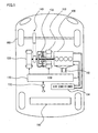
Fig. 1 , a hybrid vehicle incorporates anengine 100, afirst motor generator 110, asecond motor generator 120, apower split device 130, areduction gear 140, and abattery 150. Although a hybrid vehicle that does not have a charge function from an external power supply is described by way of example in the following description, a plug-in hybrid vehicle that has a charge function from an external power supply may be used. -
Engine 100,first motor generator 110,second motor generator 120 andbattery 150 are controlled by an ECU (Electronic Control Unit) 170. ECU 170 may be divided into a plurality of ECUs. - This vehicle runs using a driving force from at least one of
engine 100 andsecond motor generator 120. That is, either one or both ofengine 100 andsecond motor generator 120 are automatically selected as a driving source depending on the drive state. - For example,
engine 100 andsecond motor generator 120 are controlled in response to a result of operation on anaccelerator pedal 172 by a driver. The amount of operation on accelerator pedal 172 (accelerator position) is detected by an accelerator position sensor (not shown). - When the accelerator position is small and when the vehicle speed is low, for example, the hybrid vehicle runs using only
second motor generator 120 as a driving source. In this case,engine 100 is stopped. However,engine 100 may be driven for power generation, for example. - When the accelerator position is large, when the vehicle speed is high, or when an SOC (State Of Charge) of
battery 150 is low, for example,engine 100 is driven. In this case, the hybrid vehicle runs using onlyengine 100, or both ofengine 100 andsecond motor generator 120, as a driving source. -
Engine 100 is an internal combustion engine. An air-fuel mixture is burned in a combustion chamber to rotate a crankshaft serving as an output shaft. Exhaust gas emitted fromengine 100 is cleaned by acatalyst 102, and then emitted to the outside of the vehicle. Catalyst 102 performs a cleaning function when warmed up to a specific temperature. Catalyst 102 is warmed up by heat of the exhaust gas. Catalyst 102 is a three-way catalyst, for example. - Coolant of
engine 100 circulates by passing through anair conditioner 104 mounted on the hybrid vehicle.Air conditioner 104 heats the air in the vehicle interior by using the coolant ofengine 100. More specifically, the coolant introduced into a heater core and the air exchange heat, to deliver warmed air into the vehicle interior. A well-known common technique can be utilized forair conditioner 104, and thus a detailed description thereof will not be repeated. -
Engine 100,first motor generator 110 andsecond motor generator 120 are connected viapower split device 130. Motive power generated byengine 100 is split into two paths bypower split device 130. One of them is a path for drivingfront wheels 160 viareduction gear 140. The other is a path for drivingfirst motor generator 110 to generate electric power. -
First motor generator 110 is a three-phase alternating current rotating electric machine including a U-phase coil, a V-phase coil and a W-phase coil.First motor generator 110 generates electric power using motive power ofengine 100 that is split bypower split device 130. The electric power generated byfirst motor generator 110 is used depending on the running state of the vehicle or the SOC ofbattery 150. For example, during normal running, electric power generated byfirst motor generator 110 is directly used as electric power for drivingsecond motor generator 120. On the other hand, when the SOC ofbattery 150 is lower than a predetermined value, electric power generated byfirst motor generator 110 is converted from alternating current into direct current by an inverter described later. Thereafter, the voltage is adjusted by a converter described later, and stored inbattery 150. - When
first motor generator 110 acts as a power generator,first motor generator 110 generates negative torque. The negative torque as used herein refers to such torque that becomes a load onengine 100. Whenfirst motor generator 110 receives power supply and acts as a motor,first motor generator 110 generates positive torque. The positive torque as used herein refers to such torque that does not become a load onengine 100, that is, such torque that assists in rotation ofengine 100. This is applicable tosecond motor generator 120. -
Second motor generator 120 is a three-phase alternating current rotating electric machine including a U-phase coil, a V-phase coil and a W-phase coil.Second motor generator 120 is driven by at least one of electric power stored inbattery 150 and electric power generated byfirst motor generator 110. - The driving force from
second motor generator 120 is transmitted tofront wheels 160 viareduction gear 140. Accordingly,second motor generator 120assists engine 100, or allows the vehicle to run with the driving force fromsecond motor generator 120. The rear wheels may be driven instead of or in addition tofront wheels 160. - During regenerative braking of the hybrid vehicle,
second motor generator 120 is driven byfront wheels 160 viareduction gear 140, causingsecond motor generator 120 to operate as a power generator. Accordingly,second motor generator 120 operates as a regenerative brake for converting braking energy into electric power. The electric power generated bysecond motor generator 120 is stored inbattery 150. - Power split
device 130 is formed of a planetary gear including a sun gear, pinion gears, a carrier, and a ring gear. The pinion gears are engaged with the sun gear and ring gear. The carrier supports the pinion gears so that they are rotatable on their own axes. The sun gear is coupled to the rotation shaft offirst motor generator 110. The carrier is coupled to the crankshaft ofengine 100. The ring gear is coupled to the rotation shaft ofsecond motor generator 120 andreduction gear 140. - Since
engine 100,first motor generator 110 andsecond motor generator 120 are coupled viapower split device 130 formed of the planetary gear, the rotational speeds ofengine 100,first motor generator 110 andsecond motor generator 120 have the relation represented by a straight line in an alignment chart. -
Battery 150 is a battery pack configured so that a plurality of battery modules, each formed by integrating a plurality of battery cells, are connected in series.Battery 150 has a voltage of about 200 V, for example.Battery 150 is charged with electric power supplied fromfirst motor generator 110 andsecond motor generator 120, as well as from a power supply outside of the vehicle. A capacitor may be used instead of or in addition tobattery 150. - Referring to
Fig. 2 , an electrical system of the hybrid vehicle is further described. The hybrid vehicle includes aconverter 200, afirst inverter 210, asecond inverter 220, and a systemmain relay 230. -
Converter 200 includes a reactor, two npn transistors, and two diodes. The reactor has one end connected to the positive electrode side of each battery, and the other end connected to a node between the two npn transistors. - The two npn transistors are connected in series. The npn transistors are controlled by
ECU 170. A diode is connected between the collector and the emitter of each npn transistor to allow current to flow from the emitter side to the collector side. - As the npn transistor, an IGBT (Insulated Gate Bipolar Transistor) can be used, for example. Instead of the npn transistor, a power switching element such as a power MOSFET (Metal Oxide Semiconductor Field-Effect Transistor) can be used.
- When electric power discharged from
battery 150 is supplied tofirst motor generator 110 orsecond motor generator 120, the voltage is boosted byconverter 200. Conversely, when electric power generated byfirst motor generator 110 orsecond motor generator 120 is charged tobattery 150, the voltage is decreased byconverter 200. - A system voltage VH between
converter 200 and each inverter is detected by avoltage sensor 180. The detection result fromvoltage sensor 180 is sent toECU 170. -
First inverter 210 includes a U-phase arm, a V-phase arm and a W-phase arm. The U-phase arm, V-phase arm and W-phase arm are connected in parallel. The U-phase arm, V-phase arm and W-phase arm each have two npn transistors connected in series. A diode is connected between the collector and the emitter of each npn transistor to allow current to flow from the emitter side to the collector side. Then, the node between the npn transistors in each arm is connected to an end different from aneutral point 112 of each coil offirst motor generator 110. -
First inverter 210 converts direct current supplied frombattery 150 into alternating current, and supplies the alternating current tofirst motor generator 110.First inverter 210 also converts alternating current generated byfirst motor generator 110 into direct current. -
Second inverter 220 includes a U-phase arm, a V-phase arm and a W-phase arm. The U-phase arm, V-phase arm and W-phase arm are connected in parallel. The U-phase arm, V-phase arm and W-phase arm each have two npn transistors connected in series. A diode is connected between the collector and the emitter of each npn transistor to allow current to flow from the emitter side to the collector side. Then, the node between the npn transistors in each arm is connected to an end different from aneutral point 122 of each coil ofsecond motor generator 120. -
Second inverter 220 converts direct current supplied frombattery 150 into alternating current, and supplies the alternating current tosecond motor generator 120.Second inverter 220 also converts alternating current generated bysecond motor generator 120 into direct current. -
Converter 200,first inverter 210 andsecond inverter 220 are controlled byECU 170. - System
main relay 230 is provided betweenbattery 150 andconverter 200. Systemmain relay 230 is a relay for switching between a state in whichbattery 150 and the electrical system are connected and a state in which they are cut off. When systemmain relay 230 is in an opened state,battery 150 is cut off from the electrical system. When systemmain relay 230 is in a closed state,battery 150 is connected to the electrical system. - The state of system
main relay 230 is controlled byECU 170. For example, whenECU 170 is activated, systemmain relay 230 is closed. WhenECU 170 is stopped, systemmain relay 230 is opened. - Referring to
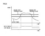
Fig. 3 , a manner in whichengine 100 is controlled is further described. As shown inFig. 3 , when output power of the hybrid vehicle is smaller than an engine start threshold value, the hybrid vehicle runs using only the driving force fromsecond motor generator 120. - The output power is set as power used for running of the hybrid vehicle. The output power is calculated by
ECU 170 in accordance with a map having the accelerator position, vehicle speed and the like as parameters, for example. It is noted that the way to calculate the output power is not limited thereto. It is noted that torque, acceleration, driving force, accelerator position or the like may be used instead of the output power. - When the output power of the hybrid vehicle becomes equal to or greater than the engine start threshold value,
engine 100 is driven. Accordingly, the hybrid vehicle runs using the driving force fromengine 100 in addition to or instead of the driving force fromsecond motor generator 120. In addition, electric power generated byfirst motor generator 110 using the driving force fromengine 100 is directly supplied tosecond motor generator 120. - As shown in
Fig. 4 , an operating point ofengine 100, namely, an engine speed NE and output torque TE are determined by a point of intersection of the output power and an operating line. - The output power is represented by equal-power lines. The operating line is predetermined by a developer based on the results of experiments and simulations. The operating line is set so that
engine 100 can be driven with optimal (highest) fuel economy. That is, the optimal fuel economy is achieved by drivingengine 100 along the operating line. It is noted that in a range between a predetermined torque TE1 and a predetermined torque TE2, the operating line is set so that vibration and noise are reduced. It is noted that the way to set the operating line is not limited thereto. - When the point of intersection of the output power and the operating line is in the range between predetermined torque TE1 and predetermined torque TE2 as shown in
Fig. 5 , the optimal fuel economy is not achieved. In view of this, to achieve the optimal fuel economy, the output power is corrected to increase when drivingengine 100, as shown inFig. 6 . Specifically, the output power is increased to achieve the optimal fuel economy. - As a result, as shown in
Fig. 7 , afterengine 100 is started at time T1, the hybrid vehicle is controlled to attain second output power P2 corrected to increase, instead of first output power P1 set based on the accelerator position. For example, the hybrid vehicle is controlled so that the output power ofengine 100 is second output power P2. - The difference between first output power P1 requested by the driver and second output power P2 is used, for example, to generate electric power using
first motor generator 110 to chargebattery 150. - After
engine 100 is started, when the output power becomes equal to or smaller than an engine stop threshold value,engine 100 is stopped. Thus, the hybrid vehicle runs using only the driving force fromsecond motor generator 120. For example, the hybrid vehicle is controlled so that the output power ofsecond motor generator 120 is first output power P1. The engine stop threshold value is set to be smaller than the engine start threshold value by the developer in consideration of hysteresis. - Whether to compare first output power P1 set based on the accelerator position with the engine stop threshold value, or to compare second output power P2 corrected to increase with the engine stop threshold value is switched depending on the drive state of the hybrid vehicle.
- Referring to
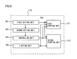
Fig. 8 , the function ofECU 170 in this embodiment is described. The function described below may be implemented by hardware, software, or cooperation of hardware and software. -
ECU 170 includes afirst setting unit 301, asecond setting unit 302, a controllingunit 304, a limitingunit 306, a first stoppingunit 311, and a second stoppingunit 312. - First setting
unit 301 sets the first output power in accordance with operation onaccelerator pedal 172 by the driver. For example, the first output power is set in accordance with a map having the accelerator position, vehicle speed and the like as parameters. -
Second setting unit 302 sets second output power P2 greater than first output power P1. Second output power P2 is set so thatengine 100 is driven at an operating point where the optimal fuel economy is achieved. -
Controlling unit 304 controlsengine 100 to drive in accordance with second output power P2. For example, the hybrid vehicle is controlled so that the output power ofengine 100 is second output power P2. -
Controlling unit 306 sets, depending on the temperature ofbattery 150, an upper limit value WOUT of electric power discharged frombattery 150. For example, upper limit value WOUT is set depending on the temperature ofbattery 150, based on a map shown inFig. 9 . It is noted that the way to set upper limit value WOUT of electric power discharged frombattery 150 is not limited thereto. The electric power discharged frombattery 150 is limited to be equal to or smaller than upper limit value WOUT. - Referring back to
Fig. 8 , when second output power P2 is equal to or smaller than the predetermined engine stop threshold value in a first state, first stoppingunit 311 controls the hybrid vehicle so thatengine 100 is stopped. - When first output power P1 is equal to or smaller than the engine threshold value in a second state different from the first state, second stopping
unit 312 controls the hybrid vehicle so thatengine 100 is stopped. - The first state includes a state where the SOC of
battery 150 is lower than a predetermined SOC, a state where the temperature of the coolant ofengine 100 is lower than a predetermined temperature, a state where upper limit value WOUT of electric power discharged frombattery 150 is smaller than a predetermined value, and a state whereair conditioner 104 is operating to heat the air in the vehicle interior. - Therefore, in a state where the SOC of
battery 150 is lower than a predetermined SOC, a state where the temperature of the coolant ofengine 100 is lower than a predetermined temperature, a state where upper limit value WOUT of electric power discharged frombattery 150 is smaller than a predetermined value, or a state whereair conditioner 104 is operating to heat the air in the vehicle interior, when second output power P2 is equal to or smaller than the predetermined engine stop threshold value, the hybrid vehicle is controlled so thatengine 100 is stopped. - The second state is a state other than the first state. Thus, the second state satisfies at least a condition that the SOC of
battery 150 is equal to or higher than the predetermined SOC. More specifically, the second state is a state where the SOC ofbattery 150 is equal to or higher than the predetermined SOC, the temperature of the coolant ofengine 100 is equal to or higher than the predetermined temperature, upper limit value WOUT of electric power discharged frombattery 150 is equal to or greater than the predetermined value, andair conditioner 104 is operating to cool the air in the vehicle interior, or is in a stopped state. - Therefore, in a state that satisfies all of the conditions that the SOC of
battery 150 is equal to or higher than the predetermined SOC, the temperature of the coolant ofengine 100 is equal to or higher than the predetermined temperature, upper limit value WOUT of electric power discharged frombattery 150 is equal to or greater than the predetermined value, andair conditioner 104 is operating to cool the air in the vehicle interior, or is in a stopped state, when first output power P1 is equal to or smaller than the engine threshold value, the hybrid vehicle is controlled so thatengine 100 is stopped. - The first and second states are not limited to these states. For example, the first state may be a state where the SOC of
battery 150 is lower than the predetermined SOC, and the second state may be a state where the SOC ofbattery 150 is equal to or higher than the predetermined SOC. - The state where the SOC of
battery 150 is lower than the predetermined SOC is a state where, in short, electric power that can be discharged frombattery 150 is smaller than a prescribed value, and electric power that can be charged tobattery 150 is greater than a prescribed value. - The state where the temperature of the coolant of
engine 100 is equal to or lower than the predetermined temperature is a state where, in short,engine 100 needs to be warmed up. - Referring to
Fig. 10 , a control configuration of the hybrid vehicle is described. - In step (hereinafter abbreviated as S) 100,
ECU 170 sets first output power P1 in accordance with operation onaccelerator pedal 172 by the driver. Namely, first output power P1 is set in accordance with the accelerator position. - In S102,
ECU 170 determines whether or not first output power P1 is equal to or greater than the engine start threshold value. If first output power P1 is equal to or greater than the engine start threshold value (YES in S 102), the process proceeds to S104. If not (NO in S102), the process proceeds to S108. - In S104,
ECU 170 sets second output power P2 greater than first output power P1. - In S106,
ECU 170 controls the hybrid vehicle so thatengine 100 is driven in accordance with second output power P2. - In S108,
ECU 170 controls the hybrid vehicle so thatengine 100 is stopped and onlysecond motor generator 120 is used as a driving source for running. For example, the hybrid vehicle is controlled so that the output power ofsecond motor generator 120 is first output power P1. - In S110,
ECU 170 determines whether or not the drive state of the vehicle is the first state. If the drive state of the vehicle is the first state (YES in S110), the process proceeds toS 112. If the drive state of the vehicle is the second state (NO in S 110), the process proceeds to S114. - In
S 112,ECU 170 determines whether or not second output power P2 is equal to or smaller than the engine stop threshold value. If second output power P2 is equal to or smaller than the engine stop threshold value (YES in S112), the process proceeds to S116. If not (NO in S 112), the process returns to S104. - In
S 114,ECU 170 determines whether or not first output power P1 is equal to or smaller than the engine stop threshold value. If first output power P1 is equal to or smaller than the engine stop threshold value (YES in S114), the process proceeds to S 116. If not (NO in S 114), the process returns toS 104. - In S 116,
ECU 170 stopsengine 100. - As described above, according to the hybrid vehicle in this embodiment,
engine 100 is controlled to be driven in accordance with second output power P2 greater than first output power P1 set in accordance with the operation onaccelerator pedal 172 by the driver. When first output power P1 is equal to or smaller than the engine stop threshold value in the second state,engine 100 is stopped. First output power P1 is smaller than second output power P2. Thus, first output power P1 is more likely than second output power P2 to become equal to or smaller than the engine start threshold value. Therefore, the frequency with whichengine 100 is stopped is increased. - As shown in
Fig. 11 , the present invention can also be applied to a hybrid vehicle incorporating only amotor generator 122 mainly used as a driving source, and not including a motor generator mainly used as a power generator. - As shown in
Fig. 12 , the present invention can also be applied to a series-type hybrid vehicle in whichengine 100 is used only to drivefirst motor generator 110, andsecond motor generator 120 is always used for running. - It should be understood that the embodiments disclosed herein are illustrative and non-restrictive in every respect. The scope of the present invention is defined by the terms of the claims, rather than the description above, and is intended to include any modifications within the scope and meaning equivalent to the terms of the claims.
- 100 engine; 102 catalyst; 104 air conditioner; 110 first motor generator; 120 second motor generator; 130 power split device; 140 reduction gear; 150 battery; 160 front wheel; 170 ECU; 172 accelerator pedal; 200 converter; 210 first inverter; 220 second inverter; 230 system main relay; 301 first setting unit; 302 second setting unit; 304 controlling unit; 306 limiting unit; 311 first stopping unit; 312 second stopping unit.
Claims (8)
- A control device for a hybrid vehicle which includes an internal combustion engine (100), an electric motor (120), and a power storage device (150) that stores electric power to be supplied to said electric motor (120), and which runs using at least one of said internal combustion engine (100) and said electric motor (120), comprising:means for setting first output power in accordance with operation by a driver;means for setting second output power greater than said first output power;means for controlling said internal combustion engine (100) to drive in accordance with said second output power; andstop means for stopping said internal combustion engine (100) when said first output power is equal to or smaller than a predetermined threshold value.
- The control device for a hybrid vehicle according to claim 1, further comprising means for stopping said internal combustion engine (100) when said second output power is equal to or smaller than said threshold value in a first state, wherein
said stop means stops said internal combustion engine (100) when said first output power is equal to or smaller than said threshold value in a second state different from said first state. - The control device for a hybrid vehicle according to claim 2, wherein
said first state includes a state where a state of charge of said power storage device (150) is lower than a predetermined state of charge, and
said second state is a state that satisfies at least a condition that the state of charge of said power storage device (150) is equal to or higher than said predetermined state of charge. - The control device for a hybrid vehicle according to claim 2, wherein
said first state includes a state where the temperature of coolant of said internal combustion engine (100) is lower than a predetermined temperature, and
said second state is a state that satisfies at least a condition that the temperature of the coolant of said internal combustion engine (100) is equal to or higher than said predetermined temperature. - The control device for a hybrid vehicle according to claim 2, further comprising means for setting, depending on the temperature of said power storage device (150), an upper limit value of electric power discharged from said power storage device (150), wherein
said first state includes a state where said upper limit value is smaller than a predetermined value, and
said second state is a state that satisfies at least a condition that said upper limit value is equal to or greater than said predetermined value. - The control device for a hybrid vehicle according to claim 2, wherein
said hybrid vehicle further includes an air conditioner for heating the air in the vehicle interior by using coolant of said internal combustion engine (100),
said first state includes a state where said air conditioner is operating to heat the air in said vehicle interior, and
said second state is a state that satisfies at least a condition that said air conditioner is operating to cool the air in said vehicle interior, or a condition that said air conditioner is in a stopped state. - A control method for a hybrid vehicle which includes an internal combustion engine (100), an electric motor (120), and a power storage device (150) that stores electric power to be supplied to said electric motor (120), and which runs using at least one of said internal combustion engine (100) and said electric motor (120), comprising the steps of:setting first output power in accordance with operation by a driver;setting second output power greater than said first output power;controlling said internal combustion engine (100) to drive in accordance with said second output power; andstopping said internal combustion engine (100) when said first output power is equal to or smaller than a predetermined threshold value.
- A hybrid vehicle which includes an internal combustion engine (100), an electric motor (120), and a power storage device (150) that stores electric power to be supplied to said electric motor (120), and which runs using at least one of said internal combustion engine (100) and said electric motor (120), comprising:an operation unit (172) operated by a driver; anda control unit (170) that controls said hybrid vehicle in accordance with operation on said operation unit by the driver, whereinsaid control unit (170) sets first output power in accordance with the operation by the driver, sets second output power greater than said first output power, controls said internal combustion engine (100) to drive in accordance with said second output power, and stops said internal combustion engine (100) when said first output power is equal to or smaller than a predetermined threshold value.
Applications Claiming Priority (1)
| Application Number | Priority Date | Filing Date | Title |
|---|---|---|---|
| PCT/JP2010/059812 WO2011155037A1 (en) | 2010-06-10 | 2010-06-10 | Hybrid car control device, hybrid car control method, and hybrid car |
Publications (3)
| Publication Number | Publication Date |
|---|---|
| EP2581283A1 true EP2581283A1 (en) | 2013-04-17 |
| EP2581283A4 EP2581283A4 (en) | 2014-08-06 |
| EP2581283B1 EP2581283B1 (en) | 2015-11-11 |
Family
ID=45097667
Family Applications (1)
| Application Number | Title | Priority Date | Filing Date |
|---|---|---|---|
| EP10852876.1A Not-in-force EP2581283B1 (en) | 2010-06-10 | 2010-06-10 | Hybrid vehicle control device, hybrid vehicle control method, and hybrid vehicle |
Country Status (4)
| Country | Link |
|---|---|
| US (1) | US8718851B2 (en) |
| EP (1) | EP2581283B1 (en) |
| JP (1) | JP5549730B2 (en) |
| WO (1) | WO2011155037A1 (en) |
Families Citing this family (3)
| Publication number | Priority date | Publication date | Assignee | Title |
|---|---|---|---|---|
| JP5549730B2 (en) * | 2010-06-10 | 2014-07-16 | トヨタ自動車株式会社 | Hybrid vehicle control device, hybrid vehicle control method, and hybrid vehicle |
| JP6394580B2 (en) * | 2015-12-11 | 2018-09-26 | 株式会社デンソー | Vehicle control device |
| JP7006311B2 (en) * | 2018-01-29 | 2022-01-24 | トヨタ自動車株式会社 | Electric vehicle and control method of electric vehicle |
Citations (4)
| Publication number | Priority date | Publication date | Assignee | Title |
|---|---|---|---|---|
| JPH11299004A (en) * | 1998-04-08 | 1999-10-29 | Toyota Motor Corp | Charge control method for hybrid vehicle |
| US20050067200A1 (en) * | 2003-09-26 | 2005-03-31 | Ford Global Technologies, Llc | System and method for controlling stopping and starting of a vehicle engine |
| US20090125173A1 (en) * | 2007-11-08 | 2009-05-14 | Toyota Jidosha Kabushiki Kaisha | Hybrid vehicle with internal combustion engine and electric motor installed |
| EP2141056A1 (en) * | 2008-06-30 | 2010-01-06 | Byd Company Limited | A hybrid power system and its controlling method |
Family Cites Families (13)
| Publication number | Priority date | Publication date | Assignee | Title |
|---|---|---|---|---|
| JP4040241B2 (en) | 2000-08-03 | 2008-01-30 | トヨタ自動車株式会社 | Vehicle control device |
| JP2004076599A (en) * | 2002-08-12 | 2004-03-11 | Nissan Motor Co Ltd | Engine automatic stop and restart device for hybrid vehicle |
| JP2006094626A (en) | 2004-09-24 | 2006-04-06 | Toyota Motor Corp | Hybrid vehicle and its control method |
| JP4277849B2 (en) | 2005-04-22 | 2009-06-10 | トヨタ自動車株式会社 | Hybrid vehicle and control method thereof |
| US7632212B2 (en) | 2005-11-25 | 2009-12-15 | Toyota Jidosha Kabushiki Kaisha | Hybrid vehicle and control method of the same |
| US8649924B2 (en) * | 2007-11-30 | 2014-02-11 | Bosch Corporation | Torque control map to initiate engine startup processing in a hybrid vehicle |
| JP2009154724A (en) | 2007-12-26 | 2009-07-16 | Toyota Motor Corp | Controller for power transmission device for vehicle |
| JP5680279B2 (en) * | 2008-03-06 | 2015-03-04 | 日産自動車株式会社 | Engine stop control device for hybrid vehicle |
| JP2009248732A (en) | 2008-04-04 | 2009-10-29 | Toyota Motor Corp | Hybrid vehicle and method of controlling the same |
| DE102008020497A1 (en) * | 2008-04-23 | 2009-11-05 | Claas Selbstfahrende Erntemaschinen Gmbh | Operating method for an internal combustion engine |
| JP5176742B2 (en) * | 2008-07-18 | 2013-04-03 | マツダ株式会社 | Control method and apparatus for hybrid vehicle |
| US8755960B2 (en) * | 2009-05-14 | 2014-06-17 | GM Global Technology Operations LLC | Method for managing battery power within a hybrid powertrain system |
| JP5549730B2 (en) * | 2010-06-10 | 2014-07-16 | トヨタ自動車株式会社 | Hybrid vehicle control device, hybrid vehicle control method, and hybrid vehicle |
-
2010
- 2010-06-10 JP JP2012519169A patent/JP5549730B2/en active Active
- 2010-06-10 US US13/700,881 patent/US8718851B2/en active Active
- 2010-06-10 EP EP10852876.1A patent/EP2581283B1/en not_active Not-in-force
- 2010-06-10 WO PCT/JP2010/059812 patent/WO2011155037A1/en active Application Filing
Patent Citations (4)
| Publication number | Priority date | Publication date | Assignee | Title |
|---|---|---|---|---|
| JPH11299004A (en) * | 1998-04-08 | 1999-10-29 | Toyota Motor Corp | Charge control method for hybrid vehicle |
| US20050067200A1 (en) * | 2003-09-26 | 2005-03-31 | Ford Global Technologies, Llc | System and method for controlling stopping and starting of a vehicle engine |
| US20090125173A1 (en) * | 2007-11-08 | 2009-05-14 | Toyota Jidosha Kabushiki Kaisha | Hybrid vehicle with internal combustion engine and electric motor installed |
| EP2141056A1 (en) * | 2008-06-30 | 2010-01-06 | Byd Company Limited | A hybrid power system and its controlling method |
Non-Patent Citations (1)
| Title |
|---|
| See also references of WO2011155037A1 * |
Also Published As
| Publication number | Publication date |
|---|---|
| JPWO2011155037A1 (en) | 2013-08-01 |
| US8718851B2 (en) | 2014-05-06 |
| US20130079969A1 (en) | 2013-03-28 |
| EP2581283B1 (en) | 2015-11-11 |
| EP2581283A4 (en) | 2014-08-06 |
| JP5549730B2 (en) | 2014-07-16 |
| WO2011155037A1 (en) | 2011-12-15 |
Similar Documents
| Publication | Publication Date | Title |
|---|---|---|
| EP2743150B1 (en) | Vehicle, vehicle control method and vehicle control device | |
| US8589052B2 (en) | Vehicle control system | |
| US9145125B2 (en) | Control apparatus for vehicle | |
| WO2012131941A1 (en) | Vehicle, engine control method, and engine control device | |
| JP5714239B2 (en) | Vehicle control system | |
| JP5590157B2 (en) | Vehicle, vehicle control method, and vehicle control apparatus | |
| JP5747988B2 (en) | Vehicle, vehicle control method and control device | |
| EP2615286B1 (en) | Control device and control method for engine | |
| JP2010255504A (en) | Control device for hybrid vehicle | |
| JP2014080190A (en) | Vehicle, engine control method and engine control device | |
| EP2581283B1 (en) | Hybrid vehicle control device, hybrid vehicle control method, and hybrid vehicle | |
| JP2012075228A (en) | Apparatus for diagnosing cooling system | |
| JP2014189252A (en) | Vehicle controller | |
| JP5733331B2 (en) | Vehicle control system | |
| WO2012111068A1 (en) | Vehicle, and vehicle control method | |
| WO2012114504A1 (en) | Vehicle, and method and device for controlling vehicle | |
| JP2012228902A (en) | Vehicle control device | |
| WO2012053068A1 (en) | Vehicle, control method for power train, and control apparatus for power train | |
| JP5697397B2 (en) | Hybrid car | |
| JP2012240469A (en) | Controller of vehicle | |
| WO2012105018A1 (en) | Vehicle and method for controlling vehicle | |
| JP2012100419A (en) | Driving unit and motor vehicle |
Legal Events
| Date | Code | Title | Description |
|---|---|---|---|
| PUAI | Public reference made under article 153(3) epc to a published international application that has entered the european phase |
Free format text: ORIGINAL CODE: 0009012 |
|
| 17P | Request for examination filed |
Effective date: 20121204 |
|
| AK | Designated contracting states |
Kind code of ref document: A1 Designated state(s): AL AT BE BG CH CY CZ DE DK EE ES FI FR GB GR HR HU IE IS IT LI LT LU LV MC MK MT NL NO PL PT RO SE SI SK SM TR |
|
| DAX | Request for extension of the european patent (deleted) | ||
| A4 | Supplementary search report drawn up and despatched |
Effective date: 20140707 |
|
| RIC1 | Information provided on ipc code assigned before grant |
Ipc: B60W 10/30 20060101ALI20140701BHEP Ipc: B60W 10/26 20060101ALI20140701BHEP Ipc: B60W 20/00 20060101ALI20140701BHEP Ipc: B60W 10/06 20060101AFI20140701BHEP |
|
| RIN1 | Information on inventor provided before grant (corrected) |
Inventor name: ITOYAMA, DAISUKE C/O TOYOTA JIDOSHA KABUSHIKI KAIS Inventor name: KAMIJO, YUSUKE C/O TOYOTA JIDOSHA KABUSHIKI KAISHA Inventor name: MORISAKI, KEISUKE C/O TOYOTA JIDOSHA KABUSHIKI KAI Inventor name: YAGUCHI, HIDEAKI C/O TOYOTA JIDOSHA KABUSHIKI KAIS |
|
| REG | Reference to a national code |
Ref country code: DE Ref legal event code: R079 Ref document number: 602010029091 Country of ref document: DE Free format text: PREVIOUS MAIN CLASS: B60W0010060000 Ipc: B60W0020000000 |
|
| GRAP | Despatch of communication of intention to grant a patent |
Free format text: ORIGINAL CODE: EPIDOSNIGR1 |
|
| GRAJ | Information related to disapproval of communication of intention to grant by the applicant or resumption of examination proceedings by the epo deleted |
Free format text: ORIGINAL CODE: EPIDOSDIGR1 |
|
| GRAP | Despatch of communication of intention to grant a patent |
Free format text: ORIGINAL CODE: EPIDOSNIGR1 |
|
| RIC1 | Information provided on ipc code assigned before grant |
Ipc: B60W 10/08 20060101ALI20150424BHEP Ipc: B60W 10/26 20060101ALI20150424BHEP Ipc: B60W 10/30 20060101ALI20150424BHEP Ipc: B60K 6/445 20071001ALI20150424BHEP Ipc: B60W 10/06 20060101ALI20150424BHEP Ipc: B60W 20/00 20060101AFI20150424BHEP |
|
| INTG | Intention to grant announced |
Effective date: 20150519 |
|
| INTG | Intention to grant announced |
Effective date: 20150602 |
|
| GRAS | Grant fee paid |
Free format text: ORIGINAL CODE: EPIDOSNIGR3 |
|
| GRAA | (expected) grant |
Free format text: ORIGINAL CODE: 0009210 |
|
| AK | Designated contracting states |
Kind code of ref document: B1 Designated state(s): AL AT BE BG CH CY CZ DE DK EE ES FI FR GB GR HR HU IE IS IT LI LT LU LV MC MK MT NL NO PL PT RO SE SI SK SM TR |
|
| REG | Reference to a national code |
Ref country code: GB Ref legal event code: FG4D |
|
| REG | Reference to a national code |
Ref country code: CH Ref legal event code: EP |
|
| REG | Reference to a national code |
Ref country code: IE Ref legal event code: FG4D |
|
| REG | Reference to a national code |
Ref country code: AT Ref legal event code: REF Ref document number: 760281 Country of ref document: AT Kind code of ref document: T Effective date: 20151215 |
|
| REG | Reference to a national code |
Ref country code: DE Ref legal event code: R096 Ref document number: 602010029091 Country of ref document: DE |
|
| REG | Reference to a national code |
Ref country code: LT Ref legal event code: MG4D |
|
| REG | Reference to a national code |
Ref country code: NL Ref legal event code: MP Effective date: 20160211 |
|
| REG | Reference to a national code |
Ref country code: DE Ref legal event code: R084 Ref document number: 602010029091 Country of ref document: DE |
|
| REG | Reference to a national code |
Ref country code: AT Ref legal event code: MK05 Ref document number: 760281 Country of ref document: AT Kind code of ref document: T Effective date: 20151111 |
|
| PG25 | Lapsed in a contracting state [announced via postgrant information from national office to epo] |
Ref country code: NL Free format text: LAPSE BECAUSE OF FAILURE TO SUBMIT A TRANSLATION OF THE DESCRIPTION OR TO PAY THE FEE WITHIN THE PRESCRIBED TIME-LIMIT Effective date: 20151111 Ref country code: NO Free format text: LAPSE BECAUSE OF FAILURE TO SUBMIT A TRANSLATION OF THE DESCRIPTION OR TO PAY THE FEE WITHIN THE PRESCRIBED TIME-LIMIT Effective date: 20160211 Ref country code: IS Free format text: LAPSE BECAUSE OF FAILURE TO SUBMIT A TRANSLATION OF THE DESCRIPTION OR TO PAY THE FEE WITHIN THE PRESCRIBED TIME-LIMIT Effective date: 20160311 Ref country code: HR Free format text: LAPSE BECAUSE OF FAILURE TO SUBMIT A TRANSLATION OF THE DESCRIPTION OR TO PAY THE FEE WITHIN THE PRESCRIBED TIME-LIMIT Effective date: 20151111 Ref country code: ES Free format text: LAPSE BECAUSE OF FAILURE TO SUBMIT A TRANSLATION OF THE DESCRIPTION OR TO PAY THE FEE WITHIN THE PRESCRIBED TIME-LIMIT Effective date: 20151111 Ref country code: IT Free format text: LAPSE BECAUSE OF FAILURE TO SUBMIT A TRANSLATION OF THE DESCRIPTION OR TO PAY THE FEE WITHIN THE PRESCRIBED TIME-LIMIT Effective date: 20151111 Ref country code: LT Free format text: LAPSE BECAUSE OF FAILURE TO SUBMIT A TRANSLATION OF THE DESCRIPTION OR TO PAY THE FEE WITHIN THE PRESCRIBED TIME-LIMIT Effective date: 20151111 |
|
| PG25 | Lapsed in a contracting state [announced via postgrant information from national office to epo] |
Ref country code: SE Free format text: LAPSE BECAUSE OF FAILURE TO SUBMIT A TRANSLATION OF THE DESCRIPTION OR TO PAY THE FEE WITHIN THE PRESCRIBED TIME-LIMIT Effective date: 20151111 Ref country code: FI Free format text: LAPSE BECAUSE OF FAILURE TO SUBMIT A TRANSLATION OF THE DESCRIPTION OR TO PAY THE FEE WITHIN THE PRESCRIBED TIME-LIMIT Effective date: 20151111 Ref country code: GR Free format text: LAPSE BECAUSE OF FAILURE TO SUBMIT A TRANSLATION OF THE DESCRIPTION OR TO PAY THE FEE WITHIN THE PRESCRIBED TIME-LIMIT Effective date: 20160212 Ref country code: LV Free format text: LAPSE BECAUSE OF FAILURE TO SUBMIT A TRANSLATION OF THE DESCRIPTION OR TO PAY THE FEE WITHIN THE PRESCRIBED TIME-LIMIT Effective date: 20151111 Ref country code: PT Free format text: LAPSE BECAUSE OF FAILURE TO SUBMIT A TRANSLATION OF THE DESCRIPTION OR TO PAY THE FEE WITHIN THE PRESCRIBED TIME-LIMIT Effective date: 20160311 Ref country code: PL Free format text: LAPSE BECAUSE OF FAILURE TO SUBMIT A TRANSLATION OF THE DESCRIPTION OR TO PAY THE FEE WITHIN THE PRESCRIBED TIME-LIMIT Effective date: 20151111 Ref country code: AT Free format text: LAPSE BECAUSE OF FAILURE TO SUBMIT A TRANSLATION OF THE DESCRIPTION OR TO PAY THE FEE WITHIN THE PRESCRIBED TIME-LIMIT Effective date: 20151111 |
|
| PG25 | Lapsed in a contracting state [announced via postgrant information from national office to epo] |
Ref country code: CZ Free format text: LAPSE BECAUSE OF FAILURE TO SUBMIT A TRANSLATION OF THE DESCRIPTION OR TO PAY THE FEE WITHIN THE PRESCRIBED TIME-LIMIT Effective date: 20151111 |
|
| REG | Reference to a national code |
Ref country code: DE Ref legal event code: R097 Ref document number: 602010029091 Country of ref document: DE |
|
| PG25 | Lapsed in a contracting state [announced via postgrant information from national office to epo] |
Ref country code: SM Free format text: LAPSE BECAUSE OF FAILURE TO SUBMIT A TRANSLATION OF THE DESCRIPTION OR TO PAY THE FEE WITHIN THE PRESCRIBED TIME-LIMIT Effective date: 20151111 Ref country code: SK Free format text: LAPSE BECAUSE OF FAILURE TO SUBMIT A TRANSLATION OF THE DESCRIPTION OR TO PAY THE FEE WITHIN THE PRESCRIBED TIME-LIMIT Effective date: 20151111 Ref country code: RO Free format text: LAPSE BECAUSE OF FAILURE TO SUBMIT A TRANSLATION OF THE DESCRIPTION OR TO PAY THE FEE WITHIN THE PRESCRIBED TIME-LIMIT Effective date: 20151111 Ref country code: EE Free format text: LAPSE BECAUSE OF FAILURE TO SUBMIT A TRANSLATION OF THE DESCRIPTION OR TO PAY THE FEE WITHIN THE PRESCRIBED TIME-LIMIT Effective date: 20151111 Ref country code: DK Free format text: LAPSE BECAUSE OF FAILURE TO SUBMIT A TRANSLATION OF THE DESCRIPTION OR TO PAY THE FEE WITHIN THE PRESCRIBED TIME-LIMIT Effective date: 20151111 |
|
| PLBE | No opposition filed within time limit |
Free format text: ORIGINAL CODE: 0009261 |
|
| STAA | Information on the status of an ep patent application or granted ep patent |
Free format text: STATUS: NO OPPOSITION FILED WITHIN TIME LIMIT |
|
| 26N | No opposition filed |
Effective date: 20160812 |
|
| PG25 | Lapsed in a contracting state [announced via postgrant information from national office to epo] |
Ref country code: SI Free format text: LAPSE BECAUSE OF FAILURE TO SUBMIT A TRANSLATION OF THE DESCRIPTION OR TO PAY THE FEE WITHIN THE PRESCRIBED TIME-LIMIT Effective date: 20151111 |
|
| PG25 | Lapsed in a contracting state [announced via postgrant information from national office to epo] |
Ref country code: BE Free format text: LAPSE BECAUSE OF FAILURE TO SUBMIT A TRANSLATION OF THE DESCRIPTION OR TO PAY THE FEE WITHIN THE PRESCRIBED TIME-LIMIT Effective date: 20151111 |
|
| PG25 | Lapsed in a contracting state [announced via postgrant information from national office to epo] |
Ref country code: MC Free format text: LAPSE BECAUSE OF FAILURE TO SUBMIT A TRANSLATION OF THE DESCRIPTION OR TO PAY THE FEE WITHIN THE PRESCRIBED TIME-LIMIT Effective date: 20151111 |
|
| REG | Reference to a national code |
Ref country code: CH Ref legal event code: PL |
|
| GBPC | Gb: european patent ceased through non-payment of renewal fee |
Effective date: 20160610 |
|
| REG | Reference to a national code |
Ref country code: IE Ref legal event code: MM4A |
|
| REG | Reference to a national code |
Ref country code: FR Ref legal event code: ST Effective date: 20170228 |
|
| PG25 | Lapsed in a contracting state [announced via postgrant information from national office to epo] |
Ref country code: FR Free format text: LAPSE BECAUSE OF NON-PAYMENT OF DUE FEES Effective date: 20160630 Ref country code: CH Free format text: LAPSE BECAUSE OF NON-PAYMENT OF DUE FEES Effective date: 20160630 Ref country code: LI Free format text: LAPSE BECAUSE OF NON-PAYMENT OF DUE FEES Effective date: 20160630 |
|
| PG25 | Lapsed in a contracting state [announced via postgrant information from national office to epo] |
Ref country code: GB Free format text: LAPSE BECAUSE OF NON-PAYMENT OF DUE FEES Effective date: 20160610 Ref country code: IE Free format text: LAPSE BECAUSE OF NON-PAYMENT OF DUE FEES Effective date: 20160610 |
|
| PG25 | Lapsed in a contracting state [announced via postgrant information from national office to epo] |
Ref country code: HU Free format text: LAPSE BECAUSE OF FAILURE TO SUBMIT A TRANSLATION OF THE DESCRIPTION OR TO PAY THE FEE WITHIN THE PRESCRIBED TIME-LIMIT; INVALID AB INITIO Effective date: 20100610 Ref country code: CY Free format text: LAPSE BECAUSE OF FAILURE TO SUBMIT A TRANSLATION OF THE DESCRIPTION OR TO PAY THE FEE WITHIN THE PRESCRIBED TIME-LIMIT Effective date: 20151111 |
|
| PG25 | Lapsed in a contracting state [announced via postgrant information from national office to epo] |
Ref country code: TR Free format text: LAPSE BECAUSE OF FAILURE TO SUBMIT A TRANSLATION OF THE DESCRIPTION OR TO PAY THE FEE WITHIN THE PRESCRIBED TIME-LIMIT Effective date: 20151111 Ref country code: MK Free format text: LAPSE BECAUSE OF FAILURE TO SUBMIT A TRANSLATION OF THE DESCRIPTION OR TO PAY THE FEE WITHIN THE PRESCRIBED TIME-LIMIT Effective date: 20151111 Ref country code: MT Free format text: LAPSE BECAUSE OF NON-PAYMENT OF DUE FEES Effective date: 20160630 Ref country code: LU Free format text: LAPSE BECAUSE OF NON-PAYMENT OF DUE FEES Effective date: 20160610 |
|
| PG25 | Lapsed in a contracting state [announced via postgrant information from national office to epo] |
Ref country code: BG Free format text: LAPSE BECAUSE OF FAILURE TO SUBMIT A TRANSLATION OF THE DESCRIPTION OR TO PAY THE FEE WITHIN THE PRESCRIBED TIME-LIMIT Effective date: 20151111 |
|
| PG25 | Lapsed in a contracting state [announced via postgrant information from national office to epo] |
Ref country code: AL Free format text: LAPSE BECAUSE OF FAILURE TO SUBMIT A TRANSLATION OF THE DESCRIPTION OR TO PAY THE FEE WITHIN THE PRESCRIBED TIME-LIMIT Effective date: 20151111 |
|
| RIC2 | Information provided on ipc code assigned after grant |
Ipc: B60W 10/06 20060101ALI20150424BHEP Ipc: B60W 20/00 20160101AFI20150424BHEP Ipc: B60W 10/26 20060101ALI20150424BHEP Ipc: B60W 10/08 20060101ALI20150424BHEP Ipc: B60K 6/445 20071001ALI20150424BHEP Ipc: B60W 10/30 20060101ALI20150424BHEP |
|
| PGFP | Annual fee paid to national office [announced via postgrant information from national office to epo] |
Ref country code: DE Payment date: 20220420 Year of fee payment: 13 |
|
| P01 | Opt-out of the competence of the unified patent court (upc) registered |
Effective date: 20230427 |
|
| REG | Reference to a national code |
Ref country code: DE Ref legal event code: R119 Ref document number: 602010029091 Country of ref document: DE |
|
| PG25 | Lapsed in a contracting state [announced via postgrant information from national office to epo] |
Ref country code: DE Free format text: LAPSE BECAUSE OF NON-PAYMENT OF DUE FEES Effective date: 20240103 |