EP2581260A1 - Passenger seat for railway transport vehicle - Google Patents
Passenger seat for railway transport vehicle Download PDFInfo
- Publication number
- EP2581260A1 EP2581260A1 EP12188199.9A EP12188199A EP2581260A1 EP 2581260 A1 EP2581260 A1 EP 2581260A1 EP 12188199 A EP12188199 A EP 12188199A EP 2581260 A1 EP2581260 A1 EP 2581260A1
- Authority
- EP
- European Patent Office
- Prior art keywords
- seat
- backrest
- guide
- structural frame
- rest position
- Prior art date
- Legal status (The legal status is an assumption and is not a legal conclusion. Google has not performed a legal analysis and makes no representation as to the accuracy of the status listed.)
- Granted
Links
- 210000002105 tongue Anatomy 0.000 description 3
- 238000006073 displacement reaction Methods 0.000 description 2
- 230000000694 effects Effects 0.000 description 1
- 239000006260 foam Substances 0.000 description 1
- 238000012423 maintenance Methods 0.000 description 1
- 238000012986 modification Methods 0.000 description 1
- 230000004048 modification Effects 0.000 description 1
- 230000000284 resting effect Effects 0.000 description 1
Images


Classifications
-
- B—PERFORMING OPERATIONS; TRANSPORTING
- B60—VEHICLES IN GENERAL
- B60N—SEATS SPECIALLY ADAPTED FOR VEHICLES; VEHICLE PASSENGER ACCOMMODATION NOT OTHERWISE PROVIDED FOR
- B60N2/00—Seats specially adapted for vehicles; Arrangement or mounting of seats in vehicles
- B60N2/02—Seats specially adapted for vehicles; Arrangement or mounting of seats in vehicles the seat or part thereof being movable, e.g. adjustable
- B60N2/22—Seats specially adapted for vehicles; Arrangement or mounting of seats in vehicles the seat or part thereof being movable, e.g. adjustable the back-rest being adjustable
- B60N2/2222—Seats specially adapted for vehicles; Arrangement or mounting of seats in vehicles the seat or part thereof being movable, e.g. adjustable the back-rest being adjustable the back-rest having two or more parts
-
- B—PERFORMING OPERATIONS; TRANSPORTING
- B60—VEHICLES IN GENERAL
- B60N—SEATS SPECIALLY ADAPTED FOR VEHICLES; VEHICLE PASSENGER ACCOMMODATION NOT OTHERWISE PROVIDED FOR
- B60N2/00—Seats specially adapted for vehicles; Arrangement or mounting of seats in vehicles
- B60N2/02—Seats specially adapted for vehicles; Arrangement or mounting of seats in vehicles the seat or part thereof being movable, e.g. adjustable
- B60N2/22—Seats specially adapted for vehicles; Arrangement or mounting of seats in vehicles the seat or part thereof being movable, e.g. adjustable the back-rest being adjustable
- B60N2/2209—Seats specially adapted for vehicles; Arrangement or mounting of seats in vehicles the seat or part thereof being movable, e.g. adjustable the back-rest being adjustable by longitudinal displacement of the cushion, e.g. back-rest hinged on the bottom to the cushion and linked on the top to the vehicle frame
-
- B—PERFORMING OPERATIONS; TRANSPORTING
- B60—VEHICLES IN GENERAL
- B60N—SEATS SPECIALLY ADAPTED FOR VEHICLES; VEHICLE PASSENGER ACCOMMODATION NOT OTHERWISE PROVIDED FOR
- B60N2/00—Seats specially adapted for vehicles; Arrangement or mounting of seats in vehicles
- B60N2/64—Back-rests or cushions
- B60N2/66—Lumbar supports
- B60N2/667—Lumbar supports having flexible support member bowed by applied forces
- B60N2/6671—Lumbar supports having flexible support member bowed by applied forces with cable actuators
-
- B—PERFORMING OPERATIONS; TRANSPORTING
- B61—RAILWAYS
- B61D—BODY DETAILS OR KINDS OF RAILWAY VEHICLES
- B61D33/00—Seats
- B61D33/0007—Details; Accessories
- B61D33/0014—Seat frames
- B61D33/0021—Seat frames for adjustable or reclining seats
Definitions
- the present invention relates to the field of seats for the passengers of a railway transport vehicle, in particular for a railway vehicle of the TGV ® type for "high speed train".
- a passenger seat conventionally comprises a seat, substantially horizontal, on which is articulated a backrest, substantially vertical, the seat and the backrest being both mounted on a rigid guide frame forming the frame of the seat.
- the seat has several different positions to allow the passenger to adopt the most appropriate position when resting (rest position) or, for example, when using a laptop (working position).
- the seat angle In the working position, the seat angle, defined between the seat and the backrest, is of the order of 115 ° which allows the passenger to keep his back substantially straight when using his laptop. or when reading a book. In the rest position, the angle of the seat is of the order of 125 ° to allow the passenger to lie down.
- the seat conventionally comprises one or more jacks, controlled by the user using a joystick, which guide the inclination of the backrest and thus increase the angle of the seat.
- the seat base moves forward so that the seatback impinges only slightly on the space dedicated to the passenger seated in a seat at the rear.
- a passenger seat for a railway vehicle comprising seats aligned in line, does not allow persons with reduced mobility to access a seat located near the window, the seat of the seat located near the corridor preventing the passenger's movement.
- An immediate solution would be to increase the seat pitch but it increases the cost of travel per passenger.
- the invention relates to a passenger seat for a transport vehicle, in particular a rail vehicle, comprising a structural frame, a seat and a backrest hinged to the seat, the seat and backrest being guided by the structural frame, the backrest comprising at least an upper part and a lower part hinged together, the lower part of the backrest being articulated on the seat around a pivot connection and guided in the structural frame between at least one working position and at least one rest position of the seat, the opening angle of the seat, defined between the lower part of the backrest and the seat, being higher in the rest position than in the working position.
- a folder in two parts thus makes it possible to form a folder whose curvature is regular in the rest position while allowing it to remain straight in working position.
- the parts of the backrest also have different angles of inclination with respect to the horizontal direction.
- By increasing the inclination of the lower part of the backrest it is advantageous to limit the inclination of the upper part of the backrest resulting in an overall decrease in the overall size of the seat. This allows to obtain a wide angle of opening of the seat in the rest position while limiting the advance of the seat.
- the comfort of the passenger is improved without increasing the distance between two rows of seats, that is to say, the seat pitch.
- the seat is guided in translation in the structural frame so as to limit the size of the seat when in the rest position.
- the structural frame comprises at least two guide grooves of the backrest, the lower part of the backrest comprising at least one guide pin mounted in each guide groove of the frame, said guide fingers are arranged to translate in said grooves of guiding the backrest so as to define the angular position of the lower part of the backrest when it is guided between the working position and the rest position.
- the lower part of the backrest has only one freedom of movement in the frame which allows to adjust precisely its angular position and thus the curvature of the seat.
- said guide grooves of the file are rectilinear and extend obliquely relative to each other.
- said guide fingers are parallel. More preferably, the guide fingers are spaced apart by a fixed distance during the manipulation of the seat. The articulation of the lower part of the backrest is thus made around two axes translating parallel to each other by sliding in the guide grooves of the backrest, thus enabling a weakly consumer tilting of the rear space of the seat.
- the thickness of a guide pin is substantially equal to that of the guide groove of the file in which it is mounted. The operating clearance is then low which limits any angular movement of the lower part of the backrest in the guide grooves.
- the structural frame comprises at least two lateral supports, each lateral support having two grooves for guiding the backrest so as to guide the backrest so that precise and balanced. More preferably, the guide groove of the backrest located in the lower position is longer than the guide groove in the upper position so as to increase the angle of the seat while limiting the advance of the seat.
- the upper part of the backrest is connected to the lower part of the backrest by a pivot connection which makes it possible to ensure continuity in the curvature of the seat while allowing the lower part to drive the upper part of the backrest during of the manipulation of the seat.
- the seat comprises means for pivoting the seat towards the seat back for a given position of the seat.
- the seat can rotate to be folded back to the backrest which reduces the advance of the seat. The passage of persons with reduced mobility is then advantageously facilitated.
- the structural frame comprises at least one guide groove of the seat arranged to guide the course of the seat during its guidance between the working position and the rest position.
- the seat remains substantially horizontal for any position of the seat which ensures the comfort of the passenger.
- the seat comprising at least one guide pin mounted in the guide groove of the seat, the thickness of the guide pin is less than that of the guide groove of the seat so as to allow a pivoting of the seat and thus the passage of people with reduced mobility.
- the seat comprises a jack mounted between the seat and the structural frame arranged to move the seat between the working position and the rest position.
- a cylinder preferably pneumatic, facilitates the modification of the seat position.
- a displacement of the seat advantageously allows a coordinated movement of the lower and upper parts of the folder.
- the seat comprises a jack mounted between the lower part of the backrest and the structural frame arranged to move the lower part of the backrest between the working position and the rest position.
- the lower portion of the backrest comprises at least two parallel side bars which are curved so as to promote a regular curvature of the seat and to reduce the length of the seat which extends in the continuity of the lower part of the backrest.
- a passenger seat 1 for a railway vehicle according to the invention is represented diagrammatically on the figure 1 .
- the covering of the seat 1 (foams, etc.) has not been shown so that its internal structure is visible.
- the seat 1 comprises a structural frame which is integral with the railway vehicle (not shown).
- the structural frame comprises transverse crosspieces 2 on which can be mounted one or two seats 1.
- the transverse crosspieces 2 are preferably secured to each other and mounted to the floor of the railway vehicle via a fixing foot (not shown).
- the structural frame further comprises an upper frame 3, which extends substantially vertically and which is fixed integrally to an upper cross member 2, and a lower frame 5, which extends obliquely and which is fixed integrally to a lower cross member 2 as represented on the Figures 1 and 2 .
- the seat 1 comprises a seat 7 extending substantially horizontally and an articulated backrest on the seat 7, the backrest extending substantially vertically to support the back of a passenger sitting on the seat 7.
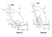
- the opening angle ⁇ of the seat 1 is defined as the angle formed between the lower part of the backrest 6 and the seat 7 as represented on the Figures 4A and 4B . Indeed, as the lower part of the backrest 6 and the seat 7 extend respectively in planes, the opening angle ⁇ of the seat 1 corresponds to the angle formed between the two planes.
- the seat 1 makes it possible to define at least one rest position PR in which the opening angle ⁇ R is of the order of 125 ° and in which the seat 7 is advanced and the backrest is inclined with respect to the position vertical as depicted on the Figure 4A .
- the rest position PR allows the passenger to lie down his body to rest. Indeed, the rest position PR makes it possible to approach the supine position while limiting the size of the seat 1 in the horizontal direction so as not to reduce the seat pitch in the railway vehicle.
- the seat 1 makes it possible to define at least one working position PT in which the opening angle ⁇ T is of the order of 115 ° and in which the seat 7 is moved backwards and the backrest is raised, close to the position vertical, as shown on the Figure 4B .
- the PT working position ensures a suitable posture for the passenger when he is, for example, reading or using a laptop or tablet.
- the backrest comprises an upper portion 4 and a lower portion 6 which are hinged together to increase the angle of the seat ⁇ while limiting the advance of the seat 7.
- the seat angle ⁇ grew linearly with the advance of the seat which penalized the seat pitch.
- the lower part of the backrest 6 makes it possible to increase the angle of the seat ⁇ while limiting the advance of the seat 7.
- the upper part 4 of the folder is in the form of a rectangular frame and substantially curved to match the shape of the passenger's back.
- the upper part 4 comprises two parallel lateral bars 41 which extend vertically and which are guided in lateral slides of the upper frame 3, the translation of the upper part 4 of the backrest with respect to the upper frame 3 being represented by an arrow T 4 on the figure 1 .
- a pneumatic jack (not shown) is placed between the lower part 6 of the backrest and the upper frame 3 to facilitate movement of the lower part of the backrest 6 between the working position and the rest position.
- the lower end of the upper part 4 of the backrest comprises a transverse bar 42 connecting the vertical side bars 41 as shown in FIG. figure 3 .
- the crossbar 42 is articulated to the lower part 6 of the backrest so as to allow pivoting about a transverse axis A.
- the articulation means 8 of the lower part 6 of the backrest on its upper part 4 will be presented later. when describing the lower part 6 of the file.
- a headrest is fixed to the upper end of the upper part 4 of the backrest so as to improve the comfort of the user in the rest position PR as in working position PT.
- the lower part 6 of the backrest has two parallel side bars 61 which are curved.
- each lateral bar 61 has successively a first straight end portion 61A, a curved portion 61B and a second straight end portion 61C as shown in FIG. figure 3 .
- the angle of curvature of a side bar 61 is of the order of 125 ° so that the seat has a regular curvature when in the rest position PR or PT working position.
- the lateral bars 61 are connected, at the first straight part 61A, by an upper transverse bar 62 and, at the curved part 61B, by an intermediate transverse bar 63.
- the hinge means 8 of the lower 6 and upper 4 of the file about the axis A are in the form of articulated tongues mounted laterally to the seat 1.
- each articulated tongue has a first end 81 secured integrally to the transverse bar 42 of the upper part 4 of the backrest and a second end 82 secured integrally to the upper transverse bar 62 of the lower part 6 of the backrest.
- Such articulation means 8 have a low cost and are simple to maintain.
- the lower part 6 of the backrest is articulated to the seat 7 so as to allow pivoting about a transverse axis B as shown in FIG. figure 3 .
- the articulation means of the lower parts 6 and the seat 7 will be presented later in the description of the seat 7.
- the lower frame 5 comprises two supports 51 which extend laterally and externally to the lower part 6 of the backrest.
- Each support 51 comprises three rectilinear guide grooves 52, 53 and 54 which guide the lower part 6 of the backrest as well as the seat 7.
- the first guide groove 52 of the support 51 located in the upper position, extends obliquely with respect to the vertical axis and forms an angle of about 138 ° with respect to the latter.
- the second guide groove 53 of the support 51 located in the intermediate position, extends obliquely with respect to the vertical axis and forms an angle of about 125 ° with respect to the latter.
- the third guide groove 54 of the support 51 located in the lower position, extends obliquely with respect to the vertical axis and forms an angle of about 106 ° with respect to the latter.
- the first and second guide grooves 52, 53 will now be presented in detail for guiding the lower part 6 of the backrest.
- the third guide groove 54 will be presented later with the seat 7.
- the first and second guide grooves 52, 53 make it possible to guide the inclination of the lower part 6 of the seat between the working positions PT and rest PR.
- the lower part 6 comprises first and second guide fingers 64, 65 arranged to translate respectively into the first and second guide grooves 52, 53 of the lower frame 5.
- a first guide pin 64 is attached to the upper end of the first straight portion 61A of each side bar 61 of the lower portion 6 of the backrest.
- a second guide pin 65 is attached to the first straight portion 61A of each side bar 61 near its curved portion 61B.
- the first and second guide fingers 64, 65 extend rectilinearly towards the supports 51 of the lower frame 5.
- the first guide fingers 64 form a first guide axis in the first grooves 52 of the supports 51 while the second guide fingers 65 form a second guide axis in the second grooves 53 of the supports 51.
- Such an assembly limits the movements of the lower part 6 of the backrest. Indeed, a guide axis can move only in a rectilinear path (guide groove) and its displacement defines the position of the other guide axis since the axes are integral with the lower portion 6. This results the lower part of the backrest 6 has only one degree of freedom and its angular inclination is perfectly defined for any position of the seat 1.
- the first and second guide fingers 64, 65 have a thickness substantially equal to the thickness of the first and second guide grooves 52, 53 so that the guidance is accurate by limiting the guide play. Thanks to the two guide grooves 52, 53, the angular inclination of the lower part 6 of the backrest is perfectly defined, only a functional guide play is allowed.
- the seat 1 is in the rest position PR while it is in the working position PT when the first and second second guide fingers 64, 65 are in upper abutment. The manipulation of the seat 1 between its different positions will be presented later.
- the length of the second rectilinear guide groove 53 is greater than that of the first rectilinear guide groove 52 so as to increase the angle of the seat on a reduced stroke of the seat 7.
- the seat 7 comprises two parallel lateral bars 71 which extend substantially horizontally and a transverse bar 72 connecting the front ends of the lateral bars 71.
- the hinge means 9 of the lower part 6 of the backrest and the seat 7 around the axis B are in the form of axles mounted laterally to the seat 1.
- the rear part of each horizontal bar 71 of the seat 7 comprises a vertical tongue 91 connected to the side bar 61 of the lower part 6 of the backrest by a rod 92 passing through its straight portion 61C in its transverse direction.
- Such articulation means 9 have a low cost and are simple to maintain.
- each guide pin 73 of the seat 7 is rectilinear and extends transversely towards its support 51 from the rear end of each lateral bar 71 of the seat 7.
- the guide pin 73 of the seat 7 has a thickness substantially equal to that of the first and second guide fingers 64, 65 of the lower part 6 of the folder.
- the third guide groove 54 has, unlike the first and second guide grooves 52, 53, a thickness wider than that of the finger 73 which it guides.
- the third guide groove 54 has a thickness substantially twice as large as that of the guide pin 73 of the seat 7 as shown in FIG. figure 3 . This allows, advantageously, a pivoting of the seat 7 towards the backrest around the pivot axis B as represented by the arrow P on the figure 3 .
- the pivoting of the seat 7 advantageously frees space at the front of the seat 1, for example, to allow the passage of people with reduced mobility.
- the guide pin 73 of the seat 7 is in contact with the upper edge of the third guide groove 54 when using the seat (horizontal seat) while the guide pin 73 of the seat 7 is in position. contact with the lower edge of the third guide groove 54 when the seat 7 is raised (vertical seat).
- the seat 1 When the guide pin 73 of the seat 7 is in forward abutment in the third guide groove 54, the seat 1 is in the rest position PR while it is in the working position PT when the guide pin 73 of the seat 7 is in rear stop.
- At least one jack 10 preferably pneumatic
- a first end is fixed to the seat 7 and a second end is fixed to the frame.
- a pneumatic cylinder 10 is attached to each side bar 71 of the seat 7 and extends parallel thereto.
- the pneumatic cylinder 10 has a longer length in the rest position PR than in PT working position.
- the seat 1 advantageously comprises control means (not shown) for controlling the length of the jack 10 and thus facilitate the handling of the seat 1 between the rest positions PR and working PT.
- control means not shown
- the seat 7 is moved back so that the third guide pin 73 is in rear abutment in the third guide groove 54 of the lower frame 5.
- the first and second guide fingers 64, 65 are in upper abutment in their first and second guide grooves 52, 53.
- the lower and upper portions 4 of the backrest are aligned similarly to the prior art. which makes it possible to form a right file.
- the angle of the seat ⁇ T is of the order of 115 ° and the horizontal advancing distance D T of the seat 1 is minimal as shown in FIG. Figure 4B .
- the seat 7 can be raised to the backrest by pivoting about the pivot axis B which is possible due to the play in translation between the third guide pin 73 and the third guide groove 54.
- the passenger controls the pneumatic cylinders 10, for example by means of a button installed in an armrest of the seat 1, so that the latter elongate.
- the pneumatic cylinders are not controlled by the passenger but dimensioned to facilitate the passage of the seat from the rest position PR to the working position PT, the cylinders providing passive assistance.
- the guide fingers 64, 65, 73 are translated into their respective guide grooves 52, 53, 54 which has the effect of moving the seat 7 forward.
- upper 4 of the backrest being guided in the upper frame 3, the angle formed between the lower 6 and upper 4 of the folder increases due to the rotation of the lower part 6 of the file about the axis A.
- the seat 7 being guided in the lower frame 5, the angle ⁇ formed between the lower part 6 of the backrest and the seat 7 increases due to the rotation of the lower part 6 of the file about the axis B.
- the lower part 6 of the backrest to form a seat 1 of regular curvature which ensures optimal comfort in the rest position while limiting the advance of the seat 7.
- the lower part 6 of the folder advantageously allows to participate in the horizontal maintenance of the passenger in rest position PR.
- the seat 7 is advanced so that the third guide pin 73 is in forward abutment in the third guide groove 54 of the lower frame 5.
- first and second guide fingers 64, 65 are in lower abutment in their first and second guide grooves 52, 53 in the rest position PR.
- the angle of the seat ⁇ R is of the order of 125 ° and the horizontal forward distance D R of the seat 1 is maximum as shown in FIG. Figure 4A .
- the seat 7 can be raised to the backrest by pivoting about the pivot axis B which is possible due to the play in translation between the third finger guide 73 and the third guide groove 54.
- the seat 1 comprises a lumbar support 11 mounted between the transverse bars 61 of the lower part 6 of the backrest as shown in FIG. figure 3 .
- a lumbar support 11 is known in itself to those skilled in the art and will not be detailed further.
- the lumbar support 11 may advantageously be controlled to exert a lumbar support of determined value.
- the seat 1 comprises a control cable (not shown) connecting the lumbar support 11 to the seat control means (not shown), preferably installed in an armrest of the seat 1.
- the lumbar support is a function of the tension of the cable.
- the control means advantageously make it possible to adjust the tension of the cable and, consequently, the value of the lumbar support.
- the seat 1 comprises a control cable (not shown) connecting the lumbar support 11 to the upper part 4 of the folder.
- the tension of the cable is changed according to the variations in distance between the lower parts 6 and upper 4 of the folder.
- the tension of the control cable is modified according to the position of the seat 1.
- the tension of the control cable can be adjusted so that the value of the support lumbar is adjusted according to the position of the seat 1.
- the adjustment of the lumbar support is automatic and it is not necessary to provide dedicated control means in the seat 1, the control of the lumbar support being related to the control of the seat position 1 which is advantageous.
Landscapes
- Engineering & Computer Science (AREA)
- Mechanical Engineering (AREA)
- Aviation & Aerospace Engineering (AREA)
- Transportation (AREA)
- Seats For Vehicles (AREA)
Abstract
Description
La présente invention concerne le domaine des sièges pour les passagers d'un véhicule ferroviaire de transport, en particulier, pour un véhicule ferroviaire du type TGV ® pour « train à grande vitesse ».The present invention relates to the field of seats for the passengers of a railway transport vehicle, in particular for a railway vehicle of the TGV ® type for "high speed train".
Un siège passager comporte de manière classique une assise, sensiblement horizontale, sur laquelle est articulé un dossier, sensiblement vertical, l'assise et le dossier étant tous les deux montés sur un châssis rigide de guidage formant l'ossature du siège. Traditionnellement, le siège comporte plusieurs positions différentes pour permettre au passager d'adopter la position la plus adéquate lorsqu'il se repose (position de repos) ou, par exemple, lorsqu'il utilise un ordinateur portable (position de travail).A passenger seat conventionally comprises a seat, substantially horizontal, on which is articulated a backrest, substantially vertical, the seat and the backrest being both mounted on a rigid guide frame forming the frame of the seat. Traditionally, the seat has several different positions to allow the passenger to adopt the most appropriate position when resting (rest position) or, for example, when using a laptop (working position).
En position de travail, l'angle de siège, défini entre l'assise et le bas de dossier, est de l'ordre de 115° ce qui permet au passager de conserver son dos sensiblement droit lors de l'utilisation de son ordinateur portable ou lors de la lecture d'un livre. En position de repos, l'angle du siège est de l'ordre de 125° pour permettre au passager de s'allonger. Pour basculer de la position de travail à la position de repos, le siège comporte de manière classique un ou plusieurs vérins, commandés par l'utilisateur à l'aide d'une manette, qui viennent guider l'inclinaison du dossier et ainsi augmenter l'angle du siège. Lors de l'inclinaison, l'assise du siège se déplace vers l'avant afin que le dossier du siège n'empiète que faiblement sur l'espace dédié au passager assis sur un siège situé à l'arrière.In the working position, the seat angle, defined between the seat and the backrest, is of the order of 115 ° which allows the passenger to keep his back substantially straight when using his laptop. or when reading a book. In the rest position, the angle of the seat is of the order of 125 ° to allow the passenger to lie down. To switch from the working position to the rest position, the seat conventionally comprises one or more jacks, controlled by the user using a joystick, which guide the inclination of the backrest and thus increase the angle of the seat. When tilting, the seat base moves forward so that the seatback impinges only slightly on the space dedicated to the passenger seated in a seat at the rear.
Pour améliorer le confort des passagers, il a été proposé d'augmenter l'angle de siège en position de repos. Pour ce faire, une solution immédiate consiste à augmenter la distance entre deux rangées de sièges, c'est-à-dire le pas de siège, afin de ménager suffisamment de place à l'assise pour se translater horizontalement vers l'avant pour permettre une forte inclinaison du dossier. Une telle solution n'est pas envisageable car une augmentation du pas de siège diminue le nombre de sièges de passager par voiture et par conséquent augmente le coût du voyage par passager.To improve the comfort of the passengers, it has been proposed to increase the seat angle in the rest position. To do this, an immediate solution is to increase the distance between two rows of seats, that is to say the seat pitch, to provide enough room for the seat to translate horizontally forward to allow a strong inclination of the file. Such a solution is not possible because an increase in the seat pitch reduces the number of passenger seats per car and therefore increases the cost of travel per passenger.
Par ailleurs, pour un véhicule ferroviaire comportant des sièges alignés en file, un siège passager selon l'art antérieur ne permet pas à des personnes à mobilité réduite d'accéder à un siège situé à proximité de la fenêtre, l'assise du siège situé à proximité du couloir empêchant la circulation du passager. Une solution immédiate serait d'augmenter le pas de siège mais cela augmente le coût du voyage par passager.Moreover, for a railway vehicle comprising seats aligned in line, a passenger seat according to the prior art does not allow persons with reduced mobility to access a seat located near the window, the seat of the seat located near the corridor preventing the passenger's movement. An immediate solution would be to increase the seat pitch but it increases the cost of travel per passenger.
Afin d'éliminer au moins certains de ces inconvénients, l'invention concerne un siège de passager pour véhicule de transport, notamment ferroviaire, comportant un châssis structural, une assise et un dossier articulé sur l'assise, l'assise et le dossier étant guidés par le châssis structural, le dossier comportant au moins une partie supérieure et une partie inférieure articulées entre elles, la partie inférieure du dossier étant articulée sur l'assise autour d'une liaison pivot et guidée dans le châssis structural entre au moins une position de travail et au moins une position de repos du siège, l'angle d'ouverture du siège, définie entre la partie inférieure du dossier et l'assise, étant supérieure en position de repos qu'en position de travail.In order to eliminate at least some of these drawbacks, the invention relates to a passenger seat for a transport vehicle, in particular a rail vehicle, comprising a structural frame, a seat and a backrest hinged to the seat, the seat and backrest being guided by the structural frame, the backrest comprising at least an upper part and a lower part hinged together, the lower part of the backrest being articulated on the seat around a pivot connection and guided in the structural frame between at least one working position and at least one rest position of the seat, the opening angle of the seat, defined between the lower part of the backrest and the seat, being higher in the rest position than in the working position.
Un dossier en deux parties permet ainsi de former un dossier dont la courbure est régulière en position de repos tout en permettant qu'il demeure droit en position de travail. Les parties du dossier possèdent en outre des angles d'inclinaison différents par rapport à la direction horizontale. En augmentant l'inclinaison de la partie inférieure du dossier, on limite de manière avantageuse l'inclinaison de la partie supérieure du dossier ce qui entraîne une diminution globale de l'encombrement du siège. Cela permet d'obtenir un grand angle d'ouverture du siège en position de repos tout en limitant l'avancée de l'assise. Ainsi, le confort du passager est amélioré sans augmenter la distance entre deux rangées de sièges, c'est-à-dire, le pas de siège.A folder in two parts thus makes it possible to form a folder whose curvature is regular in the rest position while allowing it to remain straight in working position. The parts of the backrest also have different angles of inclination with respect to the horizontal direction. By increasing the inclination of the lower part of the backrest, it is advantageous to limit the inclination of the upper part of the backrest resulting in an overall decrease in the overall size of the seat. This allows to obtain a wide angle of opening of the seat in the rest position while limiting the advance of the seat. Thus, the comfort of the passenger is improved without increasing the distance between two rows of seats, that is to say, the seat pitch.
De manière préférée, l'assise est guidée en translation dans le châssis structural de manière à limiter l'encombrement du siège lorsqu'il est en position de repos.Preferably, the seat is guided in translation in the structural frame so as to limit the size of the seat when in the rest position.
De préférence, le châssis structural comporte au moins deux rainures de guidage du dossier, la partie inférieure du dossier comportant au moins un doigt de guidage monté dans chaque rainure de guidage du châssis, lesdits doigts de guidage sont agencés pour se translater dans lesdites rainures de guidage du dossier de manière à définir la position angulaire de la partie inférieure du dossier lors de son guidage entre la position de travail et la position de repos. La partie inférieure du dossier ne possède qu'une unique liberté de mouvement dans le châssis ce qui permet de régler avec précision sa position angulaire et donc la courbure du siège.Preferably, the structural frame comprises at least two guide grooves of the backrest, the lower part of the backrest comprising at least one guide pin mounted in each guide groove of the frame, said guide fingers are arranged to translate in said grooves of guiding the backrest so as to define the angular position of the lower part of the backrest when it is guided between the working position and the rest position. The lower part of the backrest has only one freedom of movement in the frame which allows to adjust precisely its angular position and thus the curvature of the seat.
De manière préférée, lesdites rainures de guidage du dossier sont rectilignes et s'étendent obliquement l'une par rapport à l'autre. Autrement dit, les rainures de guidage du dossier ne sont pas parallèles. De manière préférée, lesdits doigts de guidage sont parallèles. De préférence encore, les doigts de guidage sont écartés d'une distance fixe au cours de la manipulation du siège. L'articulation de la partie inférieure du dossier est ainsi réalisée autour de deux axes se translatant parallèlement entre eux par coulissement dans les rainures de guidage du dossier, permettant ainsi un basculement faiblement consommateur de l'espace arrière du siège.Preferably, said guide grooves of the file are rectilinear and extend obliquely relative to each other. In other words, the guide grooves of the folder are not parallel. In a preferred manner, said guide fingers are parallel. More preferably, the guide fingers are spaced apart by a fixed distance during the manipulation of the seat. The articulation of the lower part of the backrest is thus made around two axes translating parallel to each other by sliding in the guide grooves of the backrest, thus enabling a weakly consumer tilting of the rear space of the seat.
De préférence encore, l'épaisseur d'un doigt de guidage est sensiblement égale à celle de la rainure de guidage du dossier dans lequel il est monté. Le jeu de fonctionnement est alors faible ce qui limite tout mouvement angulaire de la de la partie inférieure du dossier dans les rainures de guidage.More preferably, the thickness of a guide pin is substantially equal to that of the guide groove of the file in which it is mounted. The operating clearance is then low which limits any angular movement of the lower part of the backrest in the guide grooves.
De préférence, le châssis structural comporte au moins deux supports latéraux, chaque support latéral comportant deux rainures de guidage du dossier de manière à guider le dossier de manière précise et équilibrée. De préférence encore, la rainure de guidage du dossier située en position inférieure est plus longue que la rainure de guidage située en position supérieure de manière à augmenter l'angle du siège tout en limitant l'avancée de l'assise.Preferably, the structural frame comprises at least two lateral supports, each lateral support having two grooves for guiding the backrest so as to guide the backrest so that precise and balanced. More preferably, the guide groove of the backrest located in the lower position is longer than the guide groove in the upper position so as to increase the angle of the seat while limiting the advance of the seat.
De manière avantageuse, la partie supérieure du dossier est reliée à la partie inférieure du dossier par une liaison pivot ce qui permet d'assurer une continuité dans la courbure du siège tout en permettant à la partie inférieure d'entraîner la partie supérieure du dossier lors de la manipulation du siège.Advantageously, the upper part of the backrest is connected to the lower part of the backrest by a pivot connection which makes it possible to ensure continuity in the curvature of the seat while allowing the lower part to drive the upper part of the backrest during of the manipulation of the seat.
Selon un aspect de l'invention, le siège comporte des moyens de pivotement de l'assise vers le dossier du siège pour une position donnée du siège. Pour toute position du siège (position de repos, position de travail ou position intermédiaire), l'assise peut pivoter pour être repliée vers le dossier ce qui permet de diminuer l'avancée de l'assise. Le passage de personnes à mobilité réduite est alors avantageusement facilité.According to one aspect of the invention, the seat comprises means for pivoting the seat towards the seat back for a given position of the seat. For any position of the seat (rest position, working position or intermediate position), the seat can rotate to be folded back to the backrest which reduces the advance of the seat. The passage of persons with reduced mobility is then advantageously facilitated.
De préférence, le châssis structural comporte au moins une rainure de guidage de l'assise agencée pour guider la course de l'assise lors de son guidage entre la position de travail et la position de repos. Ainsi, l'assise demeure sensiblement horizontale pour toute position du siège ce qui assure le confort du passager.Preferably, the structural frame comprises at least one guide groove of the seat arranged to guide the course of the seat during its guidance between the working position and the rest position. Thus, the seat remains substantially horizontal for any position of the seat which ensures the comfort of the passenger.
De préférence encore, l'assise comportant au moins un doigt de guidage monté dans la rainure de guidage de l'assise, l'épaisseur du doigt de guidage est inférieure à celle de la rainure de guidage de l'assise de manière à autoriser un pivotement de l'assise et ainsi le passage de personnes à mobilité réduite.More preferably, the seat comprising at least one guide pin mounted in the guide groove of the seat, the thickness of the guide pin is less than that of the guide groove of the seat so as to allow a pivoting of the seat and thus the passage of people with reduced mobility.
Selon un aspect préféré, le siège comporte un vérin monté entre l'assise et le châssis structural agencé pour déplacer l'assise entre la position de travail et la position de repos. Un vérin, de préférence, pneumatique, permet de faciliter la modification de la position du siège. En outre, un déplacement de l'assise permet avantageusement un déplacement coordonné des parties inférieure et supérieure du dossier.According to a preferred aspect, the seat comprises a jack mounted between the seat and the structural frame arranged to move the seat between the working position and the rest position. A cylinder, preferably pneumatic, facilitates the modification of the seat position. In addition, a displacement of the seat advantageously allows a coordinated movement of the lower and upper parts of the folder.
De préférence encore, le siège comporte un vérin monté entre la partie inférieure du dossier et le châssis structural agencé pour déplacer la partie inférieure du dossier entre la position de travail et la position de repos.More preferably, the seat comprises a jack mounted between the lower part of the backrest and the structural frame arranged to move the lower part of the backrest between the working position and the rest position.
De préférence, la partie inférieure du dossier comporte au moins deux barres latérales parallèles qui sont incurvées de manière à favoriser une courbure régulière du siège et à réduire la longueur de l'assise qui s'étend dans la continuité de la partie inférieure du dossier.Preferably, the lower portion of the backrest comprises at least two parallel side bars which are curved so as to promote a regular curvature of the seat and to reduce the length of the seat which extends in the continuity of the lower part of the backrest.
L'invention sera mieux comprise à la lecture de la description qui va suivre, donnée uniquement à titre d'exemple, et se référant aux dessins annexés sur lesquels :
- la
figure 1 est une représentation schématique de la structure d'un siège selon l'invention ; - la
figure 2 est une vue de côté du siège de lafigure 1 ; - la
figure 3 est une vue en perspective rapprochée de la partie inférieure du dossier du siège de lafigure 1 ; - la
figure 4A est une représentation schématique de côté du siège de lafigure 1 en position de repos ; et - la
figure 4B est une représentation schématique de côté du siège de lafigure 1 en position de travail.
- the
figure 1 is a schematic representation of the structure of a seat according to the invention; - the
figure 2 is a side view of the headquarters of thefigure 1 ; - the
figure 3 is a close perspective view of the lower part of the seat back of thefigure 1 ; - the
Figure 4A is a schematic side view of the headquarters of thefigure 1 in the rest position; and - the
Figure 4B is a schematic side view of the headquarters of thefigure 1 in working position.
Il faut noter que les figures exposent l'invention de manière détaillée pour mettre en oeuvre l'invention, lesdites figures pouvant bien entendu servir à mieux définir l'invention le cas échéant.It should be noted that the figures disclose the invention in detail to implement the invention, said figures can of course be used to better define the invention where appropriate.
Un siège 1 de passager pour véhicule ferroviaire selon l'invention est représenté de manière schématique sur la
Le siège 1 comprend un châssis structural qui est solidaire du véhicule ferroviaire (non représenté). Dans cet exemple, le châssis structural comporte des traverses transversales 2 sur lesquelles peuvent être montées un ou deux sièges 1. Les traverses transversales 2 sont de préférence solidarisées entres elles et montées au plancher du véhicule ferroviaire via un pied de fixation (non représenté).The
Le châssis structural comporte en outre un châssis supérieur 3, qui s'étend sensiblement verticalement et qui est fixé solidairement à une traverse supérieure 2, et un châssis inférieur 5, qui s'étend obliquement et qui est fixé solidairement à une traverse inférieure 2 comme représenté sur les
Toujours en référence à la
Le siège 1 permet de définir au moins une position de repos PR dans laquelle l'angle d'ouverture βR est de l'ordre de 125° et dans laquelle l'assise 7 est avancée et le dossier est incliné par rapport à la position verticale comme représenté sur la
Le siège 1 permet de définir au moins une position de travail PT dans laquelle l'angle d'ouverture βT est de l'ordre de 115° et dans laquelle l'assise 7 est reculée et le dossier est relevé, proche de la position verticale, comme représentée sur la
Afin de permettre une posture adaptée au repos du passager tout en conservant un pas de siège de valeur réduite, le dossier comporte une partie supérieure 4 et une partie inférieure 6 qui sont articulées entre elles de manière à augmenter l'angle du siège β tout en limitant l'avancée de l'assise 7. Dans l'art antérieur, l'angle du siège β croissait linéairement avec l'avancée de l'assise ce qui pénalisait le pas de siège. Grâce à l'invention, la partie inférieure du dossier 6 permet d'augmenter l'angle du siège β tout en limitant l'avancée de l'assise 7.In order to allow a posture adapted to the rest of the passenger while maintaining a seat pitch of reduced value, the backrest comprises an
L'invention a été ici présentée avec un dossier en deux parties mais il va de soi qu'il pourrait en comprendre plus de deux, par exemple, trois.The invention has been presented here with a folder in two parts but it goes without saying that it could include more than two, for example, three.
En référence aux
De manière préférée, un appui-tête est fixé à l'extrémité supérieure de la partie supérieure 4 du dossier de manière à améliorer le confort de l'utilisateur en position de repos PR comme en position de travail PT.Preferably, a headrest is fixed to the upper end of the
En référence aux
Les barres latérales 61 sont reliées, au niveau de la première partie rectiligne 61A, par une barre transversale supérieure 62 et, au niveau de la partie incurvée 61B, par une barre transversale intermédiaire 63.The lateral bars 61 are connected, at the first
Dans cet exemple, en référence à la
La partie inférieure 6 du dossier est articulée à l'assise 7 de manière à autoriser un pivotement autour d'un axe transversale B comme représenté sur la
Afin que l'angle d'ouverture β du siège 1 soit défini de manière précise pour permettre un confort optimal du passager, la partie inférieure 6 du dossier est guidée dans le châssis inférieur 5 comme représenté en détails sur les
Par la suite, un unique support 51 du châssis inférieur 5 est décrit, les supports 51 étant symétriques l'un par rapport à l'autre comme représenté sur la
La première rainure de guidage 52 du support 51, située en position supérieure, s'étend obliquement par rapport à l'axe vertical et forme un angle d'environ 138° par rapport à ce dernier. La deuxième rainure de guidage 53 du support 51, située en position intermédiaire, s'étend obliquement par rapport à l'axe vertical et forme un angle d'environ 125° par rapport à ce dernier. La troisième rainure de guidage 54 du support 51, située en position inférieure, s'étend obliquement par rapport à l'axe vertical et forme un angle d'environ 106° par rapport à ce dernier.The
Les première et deuxième rainures de guidage 52, 53 vont être maintenant présentées en détails pour le guidage de la partie inférieure 6 du dossier. La troisième rainure de guidage 54 sera présentée par la suite avec l'assise 7.The first and
Les première et deuxième rainures de guidage 52, 53 permettent de guider l'inclinaison de la partie inférieure 6 du siège entre les positions de travail PT et de repos PR. Dans cet exemple, la partie inférieure 6 comporte des premiers et deuxièmes doigts de guidage 64, 65 agencés pour se translater respectivement dans les première et deuxième rainures de guidage 52, 53 du châssis inférieur 5. En référence à la
Les premiers et deuxièmes doigts de guidage 64, 65 possèdent une épaisseur sensiblement égale à l'épaisseur des première et deuxième rainures de guidage 52, 53 de manière à ce que le guidage soit précis en limitant le jeu de guidage. Grâce aux deux rainures de guidage 52, 53, l'inclinaison angulaire de la partie inférieure 6 du dossier est parfaitement définie, seule un jeu fonctionnel de guidage étant autorisé. Lorsque les premiers et deuxièmes doigts de guidage 64, 65 sont en butée inférieure dans leurs première et deuxième rainures de guidage 52, 53, le siège 1 est en position de repos PR tandis qu'il est en position de travail PT lorsque les premiers et deuxièmes doigts de guidage 64, 65 sont en butée supérieure. La manipulation du siège 1 entre ses différentes positions sera présentée par la suite.The first and
De préférence, la longueur de la deuxième rainure rectiligne de guidage 53 est supérieure à celle de la première rainure rectiligne de guidage 52 de manière à augmenter l'angle du siège sur une course réduite de l'assise 7.Preferably, the length of the second
En référence à la
Dans cet exemple, en référence à la
L'extrémité arrière de chaque barre latérale 71 de l'assise 7 comporte un doigt de guidage 73 agencé pour se translater dans la troisième rainure de guidage 54 du châssis inférieur 5. La troisième rainure de guidage 54 permet de guider la course horizontale de l'assise 7 entre les positions de travail PT et de repos PR. En référence à la
Le doigt de guidage 73 de l'assise 7 possède une épaisseur sensiblement égale à celle des premiers et deuxièmes doigts de guidage 64, 65 de la partie inferieure 6 du dossier. La troisième rainure de guidage 54 comporte, contrairement aux première et deuxième rainures de guidage 52, 53, une épaisseur plus large que celle du doigt 73 qu'elle guide. Dans cet exemple, la troisième rainure de guidage 54 comporte une épaisseur sensiblement deux fois plus grande que celle du doigt de guidage 73 de l'assise 7 comme représenté sur la
Lorsque le doigt de guidage 73 de l'assise 7 est en butée avant dans la troisième rainure de guidage 54, le siège 1 est en position de repos PR tandis qu'il est en position de travail PT lorsque le doigt de guidage 73 de l'assise 7 est en butée arrière.When the
De manière préférée, pour faciliter la manipulation du siège 1, il est prévu au moins un vérin 10, de préférence pneumatique, dont une première extrémité est fixée à l'assise 7 et dont une deuxième extrémité est fixée au châssis. Dans cet exemple, en référence à la
La manipulation du siège 1 entre ses différentes positions va être maintenant présentée en référence aux
En référence à la
Pour modifier la position du siège 1, le passager commande les vérins pneumatiques 10, par exemple au moyen d'un bouton installé dans un accoudoir du siège 1, de manière à ce que ces derniers s'allongent. De manière préférée, les vérins pneumatiques ne sont pas commandés par le passager mais dimensionnés pour faciliter le passage du siège de la position de repos PR à la position de travail PT, les vérins fournissant une aide passive.To change the position of the
Au fur et à mesure de l'allongement des vérins 10, les doigts de guidage 64, 65, 73 se translatent dans leurs rainures de guidage 52, 53, 54 respectives ce qui a pour effet d'avancer l'assise 7. La partie supérieure 4 du dossier étant guidée dans le châssis supérieur 3, l'angle formé entre les parties inférieure 6 et supérieure 4 du dossier augmente du fait de la rotation de la partie inférieure 6 du dossier autour de l'axe A. De manière similaire, l'assise 7 étant guidée dans le châssis inférieur 5, l'angle β formé entre la partie inférieure 6 du dossier et l'assise 7 augmente du fait de la rotation de la partie inférieure 6 du dossier autour de l'axe B. Autrement dit, la partie inférieure 6 du dossier permet de former un siège 1 de courbure régulière ce qui assure un confort optimal en position de repos tout en limitant l'avancée de l'assise 7. En effet, la partie inférieure 6 du dossier permet avantageusement de participer au maintien horizontal du passager en position de repos PR.As the
En référence à la
De manière préférée, le siège 1 comporte un support lombaire 11 monté entre les barres transversale 61 de la partie inférieure 6 du dossier comme représenté sur la
Selon un aspect de l'invention, le siège 1 comporte un câble de commande (non représenté) reliant le support lombaire 11 à des moyens de commande du siège (non représentés), de préférence, installé dans un accoudoir du siège 1. De manière classique, l'appui lombaire est fonction de la tension du câble. Les moyens de commande permettent avantageusement de régler la tension du câble et, par voie de conséquence, la valeur de l'appui lombaire.According to one aspect of the invention, the
Selon un autre aspect de l'invention, le siège 1 comporte un câble de commande (non représenté) reliant le support lombaire 11 à la partie supérieure 4 du dossier. Il en résulte que la tension du câble est modifiée en fonction des variations de distance entre les parties inférieure 6 et supérieure 4 du dossier. En d'autres termes, la tension du câble de commande est modifiée en fonction de la position du siège 1. Par connaissance, d'une part, de la plage de variation de la longueur du câble de commande entre les positions de travail PT et de repos PR et, d'autre part, de la plage de variation d'appui lombaire entre les positions de travail PT et de repos PR, on peut régler la tension du câble de commande de manière à ce que la valeur de l'appui lombaire soit ajustée en fonction de la position du siège 1. Autrement dit, le réglage de l'appui lombaire est automatique et il n'est pas nécessaire de prévoir des moyens de commande dédiés dans le siège 1, la commande de l'appui lombaire étant lié à la commande de la position du siège 1 ce qui est avantageux.According to another aspect of the invention, the
Claims (10)
Applications Claiming Priority (1)
| Application Number | Priority Date | Filing Date | Title |
|---|---|---|---|
| FR1159207A FR2981307B1 (en) | 2011-10-12 | 2011-10-12 | PASSENGER SEAT FOR RAIL TRANSPORT VEHICLE |
Publications (2)
| Publication Number | Publication Date |
|---|---|
| EP2581260A1 true EP2581260A1 (en) | 2013-04-17 |
| EP2581260B1 EP2581260B1 (en) | 2016-07-13 |
Family
ID=46970162
Family Applications (1)
| Application Number | Title | Priority Date | Filing Date |
|---|---|---|---|
| EP12188199.9A Active EP2581260B1 (en) | 2011-10-12 | 2012-10-11 | Passenger seat for railway transport vehicle |
Country Status (3)
| Country | Link |
|---|---|
| EP (1) | EP2581260B1 (en) |
| ES (1) | ES2594769T3 (en) |
| FR (1) | FR2981307B1 (en) |
Cited By (3)
| Publication number | Priority date | Publication date | Assignee | Title |
|---|---|---|---|---|
| EP2942231A1 (en) * | 2014-05-09 | 2015-11-11 | AMI Industries, Inc. | Reclining seat |
| WO2017056337A1 (en) * | 2015-10-02 | 2017-04-06 | テイ・エス テック株式会社 | Seat frame |
| CN109109889A (en) * | 2018-10-26 | 2019-01-01 | 中车南京浦镇车辆有限公司 | The mounting structure of railcar drivers' cab invaginating assistant driver seat |
Citations (4)
| Publication number | Priority date | Publication date | Assignee | Title |
|---|---|---|---|---|
| US3572829A (en) * | 1968-07-18 | 1971-03-30 | Companie Nationale Air France | Tiltable air plane seat |
| EP0016937A1 (en) * | 1979-04-07 | 1980-10-15 | Otto Zapf | Seating furniture |
| US20060082182A1 (en) * | 2004-10-20 | 2006-04-20 | Lear Corporation | Slouch rear seat system |
| EP1946958A1 (en) * | 2007-01-18 | 2008-07-23 | Nhk Spring Co.Ltd. | Vehicle seat assembly |
-
2011
- 2011-10-12 FR FR1159207A patent/FR2981307B1/en active Active
-
2012
- 2012-10-11 EP EP12188199.9A patent/EP2581260B1/en active Active
- 2012-10-11 ES ES12188199.9T patent/ES2594769T3/en active Active
Patent Citations (4)
| Publication number | Priority date | Publication date | Assignee | Title |
|---|---|---|---|---|
| US3572829A (en) * | 1968-07-18 | 1971-03-30 | Companie Nationale Air France | Tiltable air plane seat |
| EP0016937A1 (en) * | 1979-04-07 | 1980-10-15 | Otto Zapf | Seating furniture |
| US20060082182A1 (en) * | 2004-10-20 | 2006-04-20 | Lear Corporation | Slouch rear seat system |
| EP1946958A1 (en) * | 2007-01-18 | 2008-07-23 | Nhk Spring Co.Ltd. | Vehicle seat assembly |
Cited By (7)
| Publication number | Priority date | Publication date | Assignee | Title |
|---|---|---|---|---|
| EP2942231A1 (en) * | 2014-05-09 | 2015-11-11 | AMI Industries, Inc. | Reclining seat |
| US9585480B2 (en) | 2014-05-09 | 2017-03-07 | Ami Industries, Inc. | Systems and methods for reclining seats |
| EP4067165A1 (en) * | 2014-05-09 | 2022-10-05 | AMI Industries, Inc. | Reclining seat |
| WO2017056337A1 (en) * | 2015-10-02 | 2017-04-06 | テイ・エス テック株式会社 | Seat frame |
| WO2017056521A1 (en) * | 2015-10-02 | 2017-04-06 | テイ・エス テック株式会社 | Seat frame |
| US10787103B2 (en) | 2015-10-02 | 2020-09-29 | Ts Tech Co., Ltd. | Seat frame |
| CN109109889A (en) * | 2018-10-26 | 2019-01-01 | 中车南京浦镇车辆有限公司 | The mounting structure of railcar drivers' cab invaginating assistant driver seat |
Also Published As
| Publication number | Publication date |
|---|---|
| FR2981307B1 (en) | 2014-04-11 |
| EP2581260B1 (en) | 2016-07-13 |
| FR2981307A1 (en) | 2013-04-19 |
| ES2594769T3 (en) | 2016-12-22 |
Similar Documents
| Publication | Publication Date | Title |
|---|---|---|
| EP1366987B1 (en) | Seat convertible into bed having a deformable armrest | |
| EP1345810B1 (en) | Seat convertible into a bed, in particular for aircraft | |
| EP0429350B1 (en) | Improvements to front seats of motor vehicles | |
| EP2878481B1 (en) | Passenger seat with bucket structure and adjustable position | |
| EP3385115B1 (en) | Armchair for vehicle passenger comprising a resting configuration | |
| EP0575243B1 (en) | Vehicle seat with multiple adjustment | |
| EP2581260B1 (en) | Passenger seat for railway transport vehicle | |
| EP2581261B1 (en) | Passenger seat for railway transport vehicle comprising a device for adjusting the lumbar support | |
| EP2757041A1 (en) | Seat device including a seat back which can be folded forwards | |
| EP0231698B1 (en) | Folding seats for vehicles | |
| FR2599313A1 (en) | VEHICLE CENTURY HAVING A SEAT SURFACE ADJUSTABLE AT HEIGHT AND INCLINATION. | |
| EP3634177B1 (en) | Articulated seat device | |
| EP1537805B1 (en) | Resting furniture such as a sofa, arm-chair or seat for use close to a wall. | |
| FR2965716A1 (en) | Wheel chair for enabling e.g. muscular dystrophy affected person, e.g. to move to ground depending on occupation, has actuator adjusting angular position of armrests around axis of articulation with respect to backrest | |
| WO2002047513A1 (en) | Multiple-position armchair | |
| WO2016177755A1 (en) | Child car seat having adjustable strap guiding elements | |
| FR2957863A1 (en) | Retractable footrest for seat of motor vehicle, has first connecting rod whose end is articulated with end of second connecting rod, where other end of first rod and end of third connecting rod cooperate with each other by driving device | |
| FR3079464A1 (en) | VEHICLE SEAT HIGH BACK FOLDER ADJUSTMENT DEVICE, BACKREST AND VEHICLE SEAT COMPRISING SUCH HIGH BACK FILE ADJUSTMENT DEVICE | |
| FR2616719A1 (en) | Improvements to folding seats of vehicles | |
| EP2735249B1 (en) | Headboard with built-in adjustable backrest | |
| FR3074106A1 (en) | VEHICLE SEAT WITH IMPROVED COMFORT | |
| EP2014198B1 (en) | Retractable bed base and bed including such a bed base | |
| FR3125691A3 (en) | Device for adjusting the synchronized inclination of the seat cushion and the back of a seat | |
| FR2805500A1 (en) | Mechanism, for transforming adjacent rows of seats into resting couches, has link arm, stored against rear row of seats for normal access, and pivoted to attach to forward seat to form part of mechanism | |
| FR2777516A1 (en) | Vehicle seat with automatic adjustment of element of seat, |
Legal Events
| Date | Code | Title | Description |
|---|---|---|---|
| PUAI | Public reference made under article 153(3) epc to a published international application that has entered the european phase |
Free format text: ORIGINAL CODE: 0009012 |
|
| AK | Designated contracting states |
Kind code of ref document: A1 Designated state(s): AL AT BE BG CH CY CZ DE DK EE ES FI FR GB GR HR HU IE IS IT LI LT LU LV MC MK MT NL NO PL PT RO RS SE SI SK SM TR |
|
| AX | Request for extension of the european patent |
Extension state: BA ME |
|
| 17P | Request for examination filed |
Effective date: 20131014 |
|
| RBV | Designated contracting states (corrected) |
Designated state(s): AL AT BE BG CH CY CZ DE DK EE ES FI FR GB GR HR HU IE IS IT LI LT LU LV MC MK MT NL NO PL PT RO RS SE SI SK SM TR |
|
| RAP1 | Party data changed (applicant data changed or rights of an application transferred) |
Owner name: SNCF MOBILITES |
|
| 17Q | First examination report despatched |
Effective date: 20150702 |
|
| REG | Reference to a national code |
Ref country code: DE Ref legal event code: R079 Ref document number: 602012020375 Country of ref document: DE Free format text: PREVIOUS MAIN CLASS: B60N0002220000 Ipc: B60N0002660000 |
|
| GRAP | Despatch of communication of intention to grant a patent |
Free format text: ORIGINAL CODE: EPIDOSNIGR1 |
|
| RIC1 | Information provided on ipc code assigned before grant |
Ipc: B61D 33/00 20060101ALI20151118BHEP Ipc: B60N 2/22 20060101ALI20151118BHEP Ipc: B60N 2/66 20060101AFI20151118BHEP |
|
| INTG | Intention to grant announced |
Effective date: 20151214 |
|
| RIN1 | Information on inventor provided before grant (corrected) |
Inventor name: GALLAIS, CEDRIC Inventor name: PERDRIEL, PHILIPPE |
|
| GRAP | Despatch of communication of intention to grant a patent |
Free format text: ORIGINAL CODE: EPIDOSNIGR1 |
|
| INTG | Intention to grant announced |
Effective date: 20160419 |
|
| GRAS | Grant fee paid |
Free format text: ORIGINAL CODE: EPIDOSNIGR3 |
|
| GRAA | (expected) grant |
Free format text: ORIGINAL CODE: 0009210 |
|
| AK | Designated contracting states |
Kind code of ref document: B1 Designated state(s): AL AT BE BG CH CY CZ DE DK EE ES FI FR GB GR HR HU IE IS IT LI LT LU LV MC MK MT NL NO PL PT RO RS SE SI SK SM TR |
|
| REG | Reference to a national code |
Ref country code: GB Ref legal event code: FG4D Free format text: NOT ENGLISH |
|
| REG | Reference to a national code |
Ref country code: AT Ref legal event code: REF Ref document number: 811990 Country of ref document: AT Kind code of ref document: T Effective date: 20160715 Ref country code: CH Ref legal event code: EP |
|
| REG | Reference to a national code |
Ref country code: IE Ref legal event code: FG4D Free format text: LANGUAGE OF EP DOCUMENT: FRENCH |
|
| REG | Reference to a national code |
Ref country code: DE Ref legal event code: R096 Ref document number: 602012020375 Country of ref document: DE |
|
| REG | Reference to a national code |
Ref country code: NL Ref legal event code: FP |
|
| REG | Reference to a national code |
Ref country code: FR Ref legal event code: PLFP Year of fee payment: 5 |
|
| REG | Reference to a national code |
Ref country code: LT Ref legal event code: MG4D |
|
| REG | Reference to a national code |
Ref country code: ES Ref legal event code: FG2A Ref document number: 2594769 Country of ref document: ES Kind code of ref document: T3 Effective date: 20161222 |
|
| PG25 | Lapsed in a contracting state [announced via postgrant information from national office to epo] |
Ref country code: IS Free format text: LAPSE BECAUSE OF FAILURE TO SUBMIT A TRANSLATION OF THE DESCRIPTION OR TO PAY THE FEE WITHIN THE PRESCRIBED TIME-LIMIT Effective date: 20161113 Ref country code: RS Free format text: LAPSE BECAUSE OF FAILURE TO SUBMIT A TRANSLATION OF THE DESCRIPTION OR TO PAY THE FEE WITHIN THE PRESCRIBED TIME-LIMIT Effective date: 20160713 Ref country code: HR Free format text: LAPSE BECAUSE OF FAILURE TO SUBMIT A TRANSLATION OF THE DESCRIPTION OR TO PAY THE FEE WITHIN THE PRESCRIBED TIME-LIMIT Effective date: 20160713 Ref country code: FI Free format text: LAPSE BECAUSE OF FAILURE TO SUBMIT A TRANSLATION OF THE DESCRIPTION OR TO PAY THE FEE WITHIN THE PRESCRIBED TIME-LIMIT Effective date: 20160713 Ref country code: NO Free format text: LAPSE BECAUSE OF FAILURE TO SUBMIT A TRANSLATION OF THE DESCRIPTION OR TO PAY THE FEE WITHIN THE PRESCRIBED TIME-LIMIT Effective date: 20161013 Ref country code: LT Free format text: LAPSE BECAUSE OF FAILURE TO SUBMIT A TRANSLATION OF THE DESCRIPTION OR TO PAY THE FEE WITHIN THE PRESCRIBED TIME-LIMIT Effective date: 20160713 |
|
| PG25 | Lapsed in a contracting state [announced via postgrant information from national office to epo] |
Ref country code: GR Free format text: LAPSE BECAUSE OF FAILURE TO SUBMIT A TRANSLATION OF THE DESCRIPTION OR TO PAY THE FEE WITHIN THE PRESCRIBED TIME-LIMIT Effective date: 20161014 Ref country code: SE Free format text: LAPSE BECAUSE OF FAILURE TO SUBMIT A TRANSLATION OF THE DESCRIPTION OR TO PAY THE FEE WITHIN THE PRESCRIBED TIME-LIMIT Effective date: 20160713 Ref country code: LV Free format text: LAPSE BECAUSE OF FAILURE TO SUBMIT A TRANSLATION OF THE DESCRIPTION OR TO PAY THE FEE WITHIN THE PRESCRIBED TIME-LIMIT Effective date: 20160713 Ref country code: PL Free format text: LAPSE BECAUSE OF FAILURE TO SUBMIT A TRANSLATION OF THE DESCRIPTION OR TO PAY THE FEE WITHIN THE PRESCRIBED TIME-LIMIT Effective date: 20160713 Ref country code: PT Free format text: LAPSE BECAUSE OF FAILURE TO SUBMIT A TRANSLATION OF THE DESCRIPTION OR TO PAY THE FEE WITHIN THE PRESCRIBED TIME-LIMIT Effective date: 20161114 |
|
| REG | Reference to a national code |
Ref country code: DE Ref legal event code: R097 Ref document number: 602012020375 Country of ref document: DE |
|
| PG25 | Lapsed in a contracting state [announced via postgrant information from national office to epo] |
Ref country code: EE Free format text: LAPSE BECAUSE OF FAILURE TO SUBMIT A TRANSLATION OF THE DESCRIPTION OR TO PAY THE FEE WITHIN THE PRESCRIBED TIME-LIMIT Effective date: 20160713 Ref country code: RO Free format text: LAPSE BECAUSE OF FAILURE TO SUBMIT A TRANSLATION OF THE DESCRIPTION OR TO PAY THE FEE WITHIN THE PRESCRIBED TIME-LIMIT Effective date: 20160713 |
|
| PLBE | No opposition filed within time limit |
Free format text: ORIGINAL CODE: 0009261 |
|
| STAA | Information on the status of an ep patent application or granted ep patent |
Free format text: STATUS: NO OPPOSITION FILED WITHIN TIME LIMIT |
|
| PG25 | Lapsed in a contracting state [announced via postgrant information from national office to epo] |
Ref country code: BG Free format text: LAPSE BECAUSE OF FAILURE TO SUBMIT A TRANSLATION OF THE DESCRIPTION OR TO PAY THE FEE WITHIN THE PRESCRIBED TIME-LIMIT Effective date: 20161013 Ref country code: SK Free format text: LAPSE BECAUSE OF FAILURE TO SUBMIT A TRANSLATION OF THE DESCRIPTION OR TO PAY THE FEE WITHIN THE PRESCRIBED TIME-LIMIT Effective date: 20160713 Ref country code: DK Free format text: LAPSE BECAUSE OF FAILURE TO SUBMIT A TRANSLATION OF THE DESCRIPTION OR TO PAY THE FEE WITHIN THE PRESCRIBED TIME-LIMIT Effective date: 20160713 Ref country code: CZ Free format text: LAPSE BECAUSE OF FAILURE TO SUBMIT A TRANSLATION OF THE DESCRIPTION OR TO PAY THE FEE WITHIN THE PRESCRIBED TIME-LIMIT Effective date: 20160713 Ref country code: SM Free format text: LAPSE BECAUSE OF FAILURE TO SUBMIT A TRANSLATION OF THE DESCRIPTION OR TO PAY THE FEE WITHIN THE PRESCRIBED TIME-LIMIT Effective date: 20160713 |
|
| 26N | No opposition filed |
Effective date: 20170418 |
|
| REG | Reference to a national code |
Ref country code: IE Ref legal event code: MM4A |
|
| PG25 | Lapsed in a contracting state [announced via postgrant information from national office to epo] |
Ref country code: SI Free format text: LAPSE BECAUSE OF FAILURE TO SUBMIT A TRANSLATION OF THE DESCRIPTION OR TO PAY THE FEE WITHIN THE PRESCRIBED TIME-LIMIT Effective date: 20160713 |
|
| REG | Reference to a national code |
Ref country code: FR Ref legal event code: PLFP Year of fee payment: 6 |
|
| PG25 | Lapsed in a contracting state [announced via postgrant information from national office to epo] |
Ref country code: IE Free format text: LAPSE BECAUSE OF NON-PAYMENT OF DUE FEES Effective date: 20161011 |
|
| PG25 | Lapsed in a contracting state [announced via postgrant information from national office to epo] |
Ref country code: HU Free format text: LAPSE BECAUSE OF FAILURE TO SUBMIT A TRANSLATION OF THE DESCRIPTION OR TO PAY THE FEE WITHIN THE PRESCRIBED TIME-LIMIT; INVALID AB INITIO Effective date: 20121011 Ref country code: CY Free format text: LAPSE BECAUSE OF FAILURE TO SUBMIT A TRANSLATION OF THE DESCRIPTION OR TO PAY THE FEE WITHIN THE PRESCRIBED TIME-LIMIT Effective date: 20160713 |
|
| PG25 | Lapsed in a contracting state [announced via postgrant information from national office to epo] |
Ref country code: MK Free format text: LAPSE BECAUSE OF FAILURE TO SUBMIT A TRANSLATION OF THE DESCRIPTION OR TO PAY THE FEE WITHIN THE PRESCRIBED TIME-LIMIT Effective date: 20160713 Ref country code: MC Free format text: LAPSE BECAUSE OF FAILURE TO SUBMIT A TRANSLATION OF THE DESCRIPTION OR TO PAY THE FEE WITHIN THE PRESCRIBED TIME-LIMIT Effective date: 20160713 Ref country code: MT Free format text: LAPSE BECAUSE OF FAILURE TO SUBMIT A TRANSLATION OF THE DESCRIPTION OR TO PAY THE FEE WITHIN THE PRESCRIBED TIME-LIMIT Effective date: 20160713 |
|
| REG | Reference to a national code |
Ref country code: FR Ref legal event code: PLFP Year of fee payment: 7 |
|
| PG25 | Lapsed in a contracting state [announced via postgrant information from national office to epo] |
Ref country code: AL Free format text: LAPSE BECAUSE OF FAILURE TO SUBMIT A TRANSLATION OF THE DESCRIPTION OR TO PAY THE FEE WITHIN THE PRESCRIBED TIME-LIMIT Effective date: 20160713 |
|
| REG | Reference to a national code |
Ref country code: AT Ref legal event code: UEP Ref document number: 811990 Country of ref document: AT Kind code of ref document: T Effective date: 20160713 |
|
| REG | Reference to a national code |
Ref country code: BE Ref legal event code: PD Owner name: SNCF VOYAGEURS; FR Free format text: DETAILS ASSIGNMENT: CHANGE OF OWNER(S), ASSIGNMENT; FORMER OWNER NAME: SOCIETE NATIONALE SNCF Effective date: 20210916 Ref country code: BE Ref legal event code: HC Owner name: SOCIETE NATIONALE SNCF; FR Free format text: DETAILS ASSIGNMENT: CHANGE OF OWNER(S), CHANGE OF OWNER(S) NAME; FORMER OWNER NAME: SNCF MOBILITES Effective date: 20210916 |
|
| REG | Reference to a national code |
Ref country code: NL Ref legal event code: PD Owner name: SNCF VOYAGEURS; FR Free format text: DETAILS ASSIGNMENT: CHANGE OF OWNER(S), ASSIGNMENT; FORMER OWNER NAME: SOCIETE NATIONALE SNCF Effective date: 20220222 |
|
| PGFP | Annual fee paid to national office [announced via postgrant information from national office to epo] |
Ref country code: BE Payment date: 20221017 Year of fee payment: 11 |
|
| REG | Reference to a national code |
Ref country code: DE Ref legal event code: R081 Ref document number: 602012020375 Country of ref document: DE Owner name: SNCF VOYAGEURS, FR Free format text: FORMER OWNER: SNCF MOBILITES, SAINT-DENIS, FR |
|
| REG | Reference to a national code |
Ref country code: GB Ref legal event code: 732E Free format text: REGISTERED BETWEEN 20230914 AND 20230920 |
|
| REG | Reference to a national code |
Ref country code: AT Ref legal event code: PC Ref document number: 811990 Country of ref document: AT Kind code of ref document: T Owner name: SNCF VOYAGEURS, FR Effective date: 20230822 |
|
| PGFP | Annual fee paid to national office [announced via postgrant information from national office to epo] |
Ref country code: NL Payment date: 20230926 Year of fee payment: 12 Ref country code: LU Payment date: 20230926 Year of fee payment: 12 |
|
| REG | Reference to a national code |
Ref country code: LU Ref legal event code: PD Owner name: SNCF VOYAGEURS; FR Free format text: FORMER OWNER: SOCIETE NATIONALE SNCF Effective date: 20230704 Ref country code: LU Ref legal event code: HC Owner name: SOCIETE NATIONALE SNCF; FR Free format text: FORMER OWNER: SNCF MOBILITES Effective date: 20230704 |
|
| PGFP | Annual fee paid to national office [announced via postgrant information from national office to epo] |
Ref country code: GB Payment date: 20231019 Year of fee payment: 12 |
|
| PGFP | Annual fee paid to national office [announced via postgrant information from national office to epo] |
Ref country code: ES Payment date: 20231114 Year of fee payment: 12 |
|
| PGFP | Annual fee paid to national office [announced via postgrant information from national office to epo] |
Ref country code: TR Payment date: 20231005 Year of fee payment: 12 Ref country code: IT Payment date: 20231009 Year of fee payment: 12 Ref country code: FR Payment date: 20231023 Year of fee payment: 12 Ref country code: DE Payment date: 20231011 Year of fee payment: 12 Ref country code: CH Payment date: 20231102 Year of fee payment: 12 Ref country code: AT Payment date: 20230921 Year of fee payment: 12 |
|
| PGFP | Annual fee paid to national office [announced via postgrant information from national office to epo] |
Ref country code: BE Payment date: 20231016 Year of fee payment: 12 |