EP2581041A1 - Blood collection device - Google Patents
Blood collection device Download PDFInfo
- Publication number
- EP2581041A1 EP2581041A1 EP13150955.6A EP13150955A EP2581041A1 EP 2581041 A1 EP2581041 A1 EP 2581041A1 EP 13150955 A EP13150955 A EP 13150955A EP 2581041 A1 EP2581041 A1 EP 2581041A1
- Authority
- EP
- European Patent Office
- Prior art keywords
- cannula
- tubular
- blood collection
- collection device
- hub
- Prior art date
- Legal status (The legal status is an assumption and is not a legal conclusion. Google has not performed a legal analysis and makes no representation as to the accuracy of the status listed.)
- Granted
Links
- 239000008280 blood Substances 0.000 title claims abstract description 57
- 210000004369 blood Anatomy 0.000 title claims abstract description 57
- 230000007246 mechanism Effects 0.000 claims abstract description 26
- 238000013022 venting Methods 0.000 claims abstract description 25
- 239000012528 membrane Substances 0.000 claims abstract description 17
- 239000012530 fluid Substances 0.000 claims abstract description 11
- 238000004891 communication Methods 0.000 claims abstract description 10
- 239000000463 material Substances 0.000 claims abstract description 8
- 229920003023 plastic Polymers 0.000 claims description 4
- 230000003292 diminished effect Effects 0.000 claims description 2
- 210000004204 blood vessel Anatomy 0.000 description 7
- 238000001514 detection method Methods 0.000 description 4
- 238000004519 manufacturing process Methods 0.000 description 4
- 238000007789 sealing Methods 0.000 description 3
- 238000012790 confirmation Methods 0.000 description 2
- 238000001746 injection moulding Methods 0.000 description 2
- 238000001990 intravenous administration Methods 0.000 description 2
- 238000000034 method Methods 0.000 description 2
- 230000007704 transition Effects 0.000 description 2
- 241001631457 Cannula Species 0.000 description 1
- 239000004698 Polyethylene Substances 0.000 description 1
- 238000004026 adhesive bonding Methods 0.000 description 1
- 230000036772 blood pressure Effects 0.000 description 1
- 230000003111 delayed effect Effects 0.000 description 1
- 238000013461 design Methods 0.000 description 1
- 230000035515 penetration Effects 0.000 description 1
- 239000004033 plastic Substances 0.000 description 1
- -1 polyethylene Polymers 0.000 description 1
- 229920000573 polyethylene Polymers 0.000 description 1
- 229920001169 thermoplastic Polymers 0.000 description 1
- 239000004416 thermosoftening plastic Substances 0.000 description 1
- 238000003466 welding Methods 0.000 description 1
Images

Classifications
-
- A—HUMAN NECESSITIES
- A61—MEDICAL OR VETERINARY SCIENCE; HYGIENE
- A61B—DIAGNOSIS; SURGERY; IDENTIFICATION
- A61B5/00—Measuring for diagnostic purposes; Identification of persons
- A61B5/15—Devices for taking samples of blood
- A61B5/150007—Details
- A61B5/150374—Details of piercing elements or protective means for preventing accidental injuries by such piercing elements
- A61B5/150381—Design of piercing elements
- A61B5/150473—Double-ended needles, e.g. used with pre-evacuated sampling tubes
- A61B5/150488—Details of construction of shaft
-
- A—HUMAN NECESSITIES
- A61—MEDICAL OR VETERINARY SCIENCE; HYGIENE
- A61B—DIAGNOSIS; SURGERY; IDENTIFICATION
- A61B5/00—Measuring for diagnostic purposes; Identification of persons
- A61B5/15—Devices for taking samples of blood
- A61B5/150007—Details
- A61B5/150015—Source of blood
- A61B5/15003—Source of blood for venous or arterial blood
-
- A—HUMAN NECESSITIES
- A61—MEDICAL OR VETERINARY SCIENCE; HYGIENE
- A61B—DIAGNOSIS; SURGERY; IDENTIFICATION
- A61B5/00—Measuring for diagnostic purposes; Identification of persons
- A61B5/15—Devices for taking samples of blood
- A61B5/150007—Details
- A61B5/150206—Construction or design features not otherwise provided for; manufacturing or production; packages; sterilisation of piercing element, piercing device or sampling device
- A61B5/150213—Venting means
-
- A—HUMAN NECESSITIES
- A61—MEDICAL OR VETERINARY SCIENCE; HYGIENE
- A61B—DIAGNOSIS; SURGERY; IDENTIFICATION
- A61B5/00—Measuring for diagnostic purposes; Identification of persons
- A61B5/15—Devices for taking samples of blood
- A61B5/150007—Details
- A61B5/150206—Construction or design features not otherwise provided for; manufacturing or production; packages; sterilisation of piercing element, piercing device or sampling device
- A61B5/150259—Improved gripping, e.g. with high friction pattern or projections on the housing surface or an ergonometric shape
-
- A—HUMAN NECESSITIES
- A61—MEDICAL OR VETERINARY SCIENCE; HYGIENE
- A61B—DIAGNOSIS; SURGERY; IDENTIFICATION
- A61B5/00—Measuring for diagnostic purposes; Identification of persons
- A61B5/15—Devices for taking samples of blood
- A61B5/150007—Details
- A61B5/150374—Details of piercing elements or protective means for preventing accidental injuries by such piercing elements
- A61B5/150381—Design of piercing elements
- A61B5/150389—Hollow piercing elements, e.g. canulas, needles, for piercing the skin
-
- A—HUMAN NECESSITIES
- A61—MEDICAL OR VETERINARY SCIENCE; HYGIENE
- A61B—DIAGNOSIS; SURGERY; IDENTIFICATION
- A61B5/00—Measuring for diagnostic purposes; Identification of persons
- A61B5/15—Devices for taking samples of blood
- A61B5/150007—Details
- A61B5/150374—Details of piercing elements or protective means for preventing accidental injuries by such piercing elements
- A61B5/150534—Design of protective means for piercing elements for preventing accidental needle sticks, e.g. shields, caps, protectors, axially extensible sleeves, pivotable protective sleeves
- A61B5/150572—Pierceable protectors, e.g. shields, caps, sleeves or films, e.g. for hygienic purposes
-
- A—HUMAN NECESSITIES
- A61—MEDICAL OR VETERINARY SCIENCE; HYGIENE
- A61B—DIAGNOSIS; SURGERY; IDENTIFICATION
- A61B5/00—Measuring for diagnostic purposes; Identification of persons
- A61B5/15—Devices for taking samples of blood
- A61B5/153—Devices specially adapted for taking samples of venous or arterial blood, e.g. with syringes
- A61B5/1535—Devices specially adapted for taking samples of venous or arterial blood, e.g. with syringes comprising means for indicating vein or arterial entry
Definitions
- the invention relates to a blood collection device comprising a cannula hub defining a chamber, an inlet cannula and an outlet cannula both being mounted to the cannula hub and communicating with the chamber, a closed sleeve mounted over a portion of the outlet cannula disposed externally of the cannula hub, and a venting mechanism providing communication between the chamber and ambient surroundings.
- Blood collection devices of the above kind have long been used to collect blood from patients, wherein the patients' vessels from which blood is to be drawn are often rather small and/or not visible. If the tip of the inlet cannula is not in communication with the interior of the blood vessel, the procedure of collecting blood is likely to be unsuccessful and the patient may be harmed additionally by the penetration of delicate underlying structures. Accordingly, confirmation of accurate placement of the cannula tip into a blood vessel is desirable for blood drawing procedures.
- Known intravenous blood collection devices therefore include mechanisms for indicating when the inlet cannula tip is in communication with the interior of a blood vessel, for example, a transparent portion of the cannula hub from which the presence of blood can be observed.
- the observation of blood in the cannula hub is known as "flashback".
- flashback detection has been less than satisfactory for many such blood collection devices, since the flow of blood into the transparent portion of the cannula hub is impeded by air backpressure in the cannula hub and, thus, flashback confirmation is not visible or delayed. This delay can impede the determination of the precise moment at which the cannula tip enters the blood vessel, which may cause the healthcare worker inserting the needle to miss or perforate the vessel and penetrate into delicate surrounding structures.
- intravenous blood collection devices have been provided with a venting mechanism providing communication between a flashback chamber of the cannula hub and ambient surroundings.
- the blood collection device of the invention comprises a cannula hub defining a chamber; an inlet cannula defining an axis and having a distal end and a lumen extending therethrough, the inlet cannula being mounted to the cannula hub such that the distal end of the inlet cannula is external of the cannula hub and such that the lumen through the inlet cannula communicates with the chamber; an outlet cannula having a proximal end and a lumen extending therethrough, the outlet cannula being mounted to the cannula hub such that the proximal end of the outlet cannula is external of the cannula hub and such that the lumen of the outlet cannula communicates with the chamber; a closed sleeve mounted over a portion of the outlet cannula disposed externally of the cannula hub; and a venting mechanism providing communication between the chamber and ambient surroundings, wherein the venting mechanism comprises a tubular insert defining
- the blood collection device of the invention and, in particular, the specific design of its venting mechanism allows blood flashback to occur particularly rapidly upon entry of the inlet cannula into the blood vessel. This makes particularly quick and reliable venipuncture detection possible and, thus, helps to ensure that the inlet cannula is correctly placed in the patient on the first try. In the end, blood can be collected with the device of the invention in a manner that is particularly gentle on the patient.
- the inlet cannula and the outlet cannula can either be two separate parts or they can be integrally formed from a single cannula that is provided with an opening in the region of the flashback chamber which allows for communication between both the lumen of the inlet cannula and the lumen of the outlet cannula with the flashback chamber.
- the membrane can be configured such that upon contact with blood the membrane either remains permeable for air or becomes impermeable not only for blood but also for air. In the latter case the membrane could be referred to as self-sealing.
- the tubular insert of the venting mechanism is received in a tubular projection extending from the cannula hub.
- the tubular projection extends in a direction transverse, in particular perpendicular, to the axis of the inlet cannula.
- the manufacturing of the device is particularly simple and inexpensive, if the tubular projection is integral with the cannula hub, in particular with a first part of the cannula hub carrying the inlet cannula.
- the tubular insert of the venting mechanism is fixed in the tubular projection by means of a press fit.
- the tubular insert of the venting mechanism may have a collar formed on its outer surface adjacent an end facing away from the cannula hub.
- the collar fulfils a sealing function as it helps to prevent blood from exiting the flashback chamber.
- an outer diameter of the collar is substantially equal to an outer diameter of the tubular projection, since this leads to a smooth transition from collar to tubular projection in the assembled state.
- the fluid passage is diminished by an inner collar in the region of the tubular projection adjacent the chamber of the cannula hub.
- This inner collar adds to the sealing function in that it also helps to prevent blood from exiting the flashback chamber.
- the cannula hub is formed from first and second parts, the first part carrying the inlet cannula and the second part carrying the outlet cannula.
- the first part comprises a grip portion and a tubular portion extending proximal therefrom in the direction of the cannula axis.
- the grip portion makes the handling of the device easier, while the tubular portion extending therefrom may be designed to give a clear view on blood entering the flashback chamber.
- the second part is of generally tubular shape and partly received in the tubular portion of the first part by means of a press fit.
- the second part needs only to be pushed into the first part for assembly of the device, which adds to the simple and cost effective manufacturing of the device.
- the second part and at least the tubular portion of the first part are made from a transparent plastic material. This simplifies flashback detection and makes the manufacturing of the device even more cost effective, since the first and second parts can be made by injection molding and no additional windows for flash back detection have to be implemented.
- Fig. 1 is a perspective view of a blood collection device in accordance with the invention
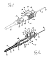
- Fig. 2 is a cross sectional view of the blood collection device of Fig. 1 ;
- Fig. 3 is a cross sectional view of a blood collection device according to a further embodiment of the invention.
- the blood collection device shown in Figs. 1 and 2 comprises a cannula hub 10 which carries an inlet cannula 12 and an outlet cannula 14.
- Inlet and outlet cannulas 12, 14 are aligned and define a needle axis.
- the inlet cannula 12 and the outlet cannula 14 form separate parts.
- the cannula hub 10 is formed from a first part 16 and a second part 18. Both the first and second parts 16, 18 are made from a transparent plastic material, e.g. by injection molding.
- the first part 16 includes a distal grip portion 20 for easy handling of the blood collection device, and a tubular portion 22 extending proximal therefrom.
- the second part 18 includes a tubular portion 24 and a threaded portion 26 extending proximal therefrom.
- the tubular portion 24 of the second part 18 has a slightly tapered outer surface and is received in the tubular portion 22 of the first part 16 by means of a press fit.
- the threaded portion 26 makes it possible to attach a blood collection tube, bag, container or the like (not shown) to the device.
- the inlet cannula 12 has a tip 30 at its distal end which is adapted to be inserted into a patient's blood vessel for drawing blood.
- the inlet cannula 12 is mounted to the first part 16 of the cannula hub 10 such that its lumen communicates with the flashback chamber 28.
- the outlet cannula 14 is mounted to the second part 18 of the cannula hub 10 such that a lumen of the outlet cannula 14 communicates with the flashback chamber 28.
- the outlet cannula 14 has a proximal portion 32 extending from the second part 18 of the cannula hub 10 which is adapted to be inserted into an blood collection tube, bag, container or the like (not shown) for collecting blood from the flashback chamber.
- the proximal portion 32 of the outlet cannula 14 is covered by a rubber sleeve 34.
- the outlet cannula 14 has a tip 36 at its proximal end for puncturing the rubber sleeve 34 when the blood collection tube, bag, container or the like is to be connected to the device.
- the blood collection device further comprises a venting mechanism 38 providing communication between the flashback chamber 28 and ambient surroundings.
- the venting mechanism 38 comprises a tubular insert 40 defining a fluid passage 42 therethrough, and a membrane 44 extending across the fluid passage 42.
- the membrane 44 sits on a shoulder 46 extending along the inner surface 48 of the tubular insert 40 and may be attached to the tubular insert 40, for example, by gluing, welding, etc.
- the membrane 44 is made from a material permeable for air and substantially impermeable for blood.
- the membrane 44 can be configured such that upon contact with blood the membrane 44 either remains permeable for air or becomes impermeable not only for blood but also for air.
- suitable materials include but are not limited to plastic, thermoplastic and polyethylene.
- the tubular insert 40 of the venting mechanism 38 is received in a tubular projection 50 which is formed integral with the first part 16 of the cannula hub 10.
- the tubular projection 50 extends perpendicularly to the needle axis from the first part 16 of the cannula hub 10, more specifically in the proximal region of the grip portion 20 thereof.
- the tubular insert 40 of the venting mechanism 38 is fixed in the tubular projection 50 by means of a press fit.
- An outer collar 52 is formed at an outer surface of the tubular insert 40 adjacent an end of the tubular insert 40 facing away from the cannula hub 10.
- the outer diameter of the collar 52 is substantially equal to an outer diameter of the tubular projection 50.
- an inner collar 54 is provided in the transition region from the tubular projection 50 to the flashback chamber 28 in the transition region from the tubular projection 50 to the flashback chamber 28, an inner collar 54 is provided.
- the length of the tubular insert 40 is selected such that the outer collar 52 abuts on the end of the tubular projection 50 facing away from the flashback chamber 28, while the end of the tubular insert 40 facing towards the flashback chamber 28 abuts on the inner collar 54, when the tubular insert 40 is fully inserted into the tubular projection 50.
- the inlet cannula 12 In use, when the inlet cannula 12 is inserted into the blood vessel of a patient blood enters the inlet cannula 12 due to the blood pressure, thereby displacing air from the lumen of the inlet cannula 12 into the flashback chamber 28. Instead of being compressed in the flashback chamber 28 and thereby building up backpressure, the displaced air can escape from the flashback chamber 28 via the membrane 44 of the venting mechanism 38, such that the blood in the inlet cannula 12 is free to flow into the flashback chamber thereby indicating successful venipuncture.
- membrane 44 as well as the press fit of the tubular insert 40 in the tubular projection 50 together with the outer and inner collars 52, 54 prevent blood from escaping the flashback chamber 28 via the venting mechanism 38.
- Fig. 3 illustrates another embodiment of a blood collection device in accordance with the invention, which is essentially identical to the blood collection device shown in Figs. 1 and 2 except for the fact that the inlet cannula 12 and the outlet cannula 14 do not form separate parts. Instead, in the blood collection device of Fig. 3 the inlet cannula 12 and the outlet cannula 14 are integrally formed from a single cannula 56 provided with an opening 58 that not only distinguishes the inlet cannula 12 from the outlet cannula 14 but also allows for communication between both the lumen of the inlet cannula 12 and the lumen of the outlet cannula 14 with the flashback chamber 28.
- the opening 58 e.g. a slot or a puncture, can be positioned anywhere in the region of the flashback chamber 28.
Landscapes
- Health & Medical Sciences (AREA)
- Life Sciences & Earth Sciences (AREA)
- Engineering & Computer Science (AREA)
- Molecular Biology (AREA)
- Animal Behavior & Ethology (AREA)
- Pathology (AREA)
- Physics & Mathematics (AREA)
- Biomedical Technology (AREA)
- Heart & Thoracic Surgery (AREA)
- Medical Informatics (AREA)
- Hematology (AREA)
- Surgery (AREA)
- Biophysics (AREA)
- General Health & Medical Sciences (AREA)
- Public Health (AREA)
- Veterinary Medicine (AREA)
- Manufacturing & Machinery (AREA)
- Vascular Medicine (AREA)
- Measurement Of The Respiration, Hearing Ability, Form, And Blood Characteristics Of Living Organisms (AREA)
- External Artificial Organs (AREA)
Abstract
Description
- RELATED APPLICATION INFORMATION
- This application claims priority from Indian Provisional Patent Application No.
1861/DEL/2009 filed onSeptember 9, 2009 - The invention relates to a blood collection device comprising a cannula hub defining a chamber, an inlet cannula and an outlet cannula both being mounted to the cannula hub and communicating with the chamber, a closed sleeve mounted over a portion of the outlet cannula disposed externally of the cannula hub, and a venting mechanism providing communication between the chamber and ambient surroundings.
- Blood collection devices of the above kind have long been used to collect blood from patients, wherein the patients' vessels from which blood is to be drawn are often rather small and/or not visible. If the tip of the inlet cannula is not in communication with the interior of the blood vessel, the procedure of collecting blood is likely to be unsuccessful and the patient may be harmed additionally by the penetration of delicate underlying structures. Accordingly, confirmation of accurate placement of the cannula tip into a blood vessel is desirable for blood drawing procedures.
- Known intravenous blood collection devices therefore include mechanisms for indicating when the inlet cannula tip is in communication with the interior of a blood vessel, for example, a transparent portion of the cannula hub from which the presence of blood can be observed. The observation of blood in the cannula hub is known as "flashback". However, flashback detection has been less than satisfactory for many such blood collection devices, since the flow of blood into the transparent portion of the cannula hub is impeded by air backpressure in the cannula hub and, thus, flashback confirmation is not visible or delayed. This delay can impede the determination of the precise moment at which the cannula tip enters the blood vessel, which may cause the healthcare worker inserting the needle to miss or perforate the vessel and penetrate into delicate surrounding structures. Accordingly, intravenous blood collection devices have been provided with a venting mechanism providing communication between a flashback chamber of the cannula hub and ambient surroundings.
- It is an object of the invention to provide a blood collection device which allows for a more efficient use and a gentler treatment of the patient and which is easy and inexpensive to manufacture.
- This object is satisfied by a blood collection device in accordance with claim 1.
- The blood collection device of the invention comprises a cannula hub defining a chamber; an inlet cannula defining an axis and having a distal end and a lumen extending therethrough, the inlet cannula being mounted to the cannula hub such that the distal end of the inlet cannula is external of the cannula hub and such that the lumen through the inlet cannula communicates with the chamber; an outlet cannula having a proximal end and a lumen extending therethrough, the outlet cannula being mounted to the cannula hub such that the proximal end of the outlet cannula is external of the cannula hub and such that the lumen of the outlet cannula communicates with the chamber; a closed sleeve mounted over a portion of the outlet cannula disposed externally of the cannula hub; and a venting mechanism providing communication between the chamber and ambient surroundings, wherein the venting mechanism comprises a tubular insert defining a fluid passage therethrough and a membrane extending across the fluid passage, wherein the membrane is made from a material permeable for air and substantially impermeable for blood.
- The blood collection device of the invention and, in particular, the specific design of its venting mechanism allows blood flashback to occur particularly rapidly upon entry of the inlet cannula into the blood vessel. This makes particularly quick and reliable venipuncture detection possible and, thus, helps to ensure that the inlet cannula is correctly placed in the patient on the first try. In the end, blood can be collected with the device of the invention in a manner that is particularly gentle on the patient.
- According to the invention, the inlet cannula and the outlet cannula can either be two separate parts or they can be integrally formed from a single cannula that is provided with an opening in the region of the flashback chamber which allows for communication between both the lumen of the inlet cannula and the lumen of the outlet cannula with the flashback chamber.
- Furthermore, the membrane can be configured such that upon contact with blood the membrane either remains permeable for air or becomes impermeable not only for blood but also for air. In the latter case the membrane could be referred to as self-sealing.
- According to an embodiment of the invention, the tubular insert of the venting mechanism is received in a tubular projection extending from the cannula hub. Preferably, the tubular projection extends in a direction transverse, in particular perpendicular, to the axis of the inlet cannula.
- The manufacturing of the device is particularly simple and inexpensive, if the tubular projection is integral with the cannula hub, in particular with a first part of the cannula hub carrying the inlet cannula.
- According to a further embodiment, the tubular insert of the venting mechanism is fixed in the tubular projection by means of a press fit. This makes the assembly of the device particularly simple and cost effective, since the venting mechanism can be prepared separately from the cannula hub, whereupon the tubular insert has merely to be pushed into the tubular projection.
- In order to prevent the tubular insert from being pushed too far into the tubular projection, the tubular insert of the venting mechanism may have a collar formed on its outer surface adjacent an end facing away from the cannula hub. In addition, the collar fulfils a sealing function as it helps to prevent blood from exiting the flashback chamber.
- Preferably, an outer diameter of the collar is substantially equal to an outer diameter of the tubular projection, since this leads to a smooth transition from collar to tubular projection in the assembled state.
- According to a further embodiment, the fluid passage is diminished by an inner collar in the region of the tubular projection adjacent the chamber of the cannula hub. This inner collar adds to the sealing function in that it also helps to prevent blood from exiting the flashback chamber.
- According to another embodiment, the cannula hub is formed from first and second parts, the first part carrying the inlet cannula and the second part carrying the outlet cannula.
- Preferably, the first part comprises a grip portion and a tubular portion extending proximal therefrom in the direction of the cannula axis. The grip portion makes the handling of the device easier, while the tubular portion extending therefrom may be designed to give a clear view on blood entering the flashback chamber.
- According to a further embodiment, the second part is of generally tubular shape and partly received in the tubular portion of the first part by means of a press fit. Thus, the second part needs only to be pushed into the first part for assembly of the device, which adds to the simple and cost effective manufacturing of the device.
- Preferably, the second part and at least the tubular portion of the first part are made from a transparent plastic material. This simplifies flashback detection and makes the manufacturing of the device even more cost effective, since the first and second parts can be made by injection molding and no additional windows for flash back detection have to be implemented.
- A preferred embodiment of the invention is described in the following description and in the accompanying drawings, wherein:
-
Fig. 1 is a perspective view of a blood collection device in accordance with the invention; -
Fig. 2 is a cross sectional view of the blood collection device ofFig. 1 ; and -
Fig. 3 is a cross sectional view of a blood collection device according to a further embodiment of the invention. - The blood collection device shown in
Figs. 1 and 2 comprises acannula hub 10 which carries aninlet cannula 12 and anoutlet cannula 14. Inlet andoutlet cannulas inlet cannula 12 and theoutlet cannula 14 form separate parts. - The
cannula hub 10 is formed from afirst part 16 and asecond part 18. Both the first andsecond parts - The
first part 16 includes adistal grip portion 20 for easy handling of the blood collection device, and atubular portion 22 extending proximal therefrom. - The
second part 18 includes atubular portion 24 and a threadedportion 26 extending proximal therefrom. Thetubular portion 24 of thesecond part 18 has a slightly tapered outer surface and is received in thetubular portion 22 of thefirst part 16 by means of a press fit. The threadedportion 26 makes it possible to attach a blood collection tube, bag, container or the like (not shown) to the device. - The
tubular portions second parts flashback chamber 28 of thecannula hub 10. - The
inlet cannula 12 has atip 30 at its distal end which is adapted to be inserted into a patient's blood vessel for drawing blood. Theinlet cannula 12 is mounted to thefirst part 16 of thecannula hub 10 such that its lumen communicates with theflashback chamber 28. - The
outlet cannula 14 is mounted to thesecond part 18 of thecannula hub 10 such that a lumen of theoutlet cannula 14 communicates with theflashback chamber 28. Theoutlet cannula 14 has aproximal portion 32 extending from thesecond part 18 of thecannula hub 10 which is adapted to be inserted into an blood collection tube, bag, container or the like (not shown) for collecting blood from the flashback chamber. Theproximal portion 32 of theoutlet cannula 14 is covered by arubber sleeve 34. Theoutlet cannula 14 has atip 36 at its proximal end for puncturing therubber sleeve 34 when the blood collection tube, bag, container or the like is to be connected to the device. - The blood collection device further comprises a
venting mechanism 38 providing communication between theflashback chamber 28 and ambient surroundings. - The
venting mechanism 38 comprises atubular insert 40 defining afluid passage 42 therethrough, and amembrane 44 extending across thefluid passage 42. Themembrane 44 sits on ashoulder 46 extending along theinner surface 48 of thetubular insert 40 and may be attached to thetubular insert 40, for example, by gluing, welding, etc. - The
membrane 44 is made from a material permeable for air and substantially impermeable for blood. Themembrane 44 can be configured such that upon contact with blood themembrane 44 either remains permeable for air or becomes impermeable not only for blood but also for air. Examples for suitable materials include but are not limited to plastic, thermoplastic and polyethylene. - The
tubular insert 40 of theventing mechanism 38 is received in atubular projection 50 which is formed integral with thefirst part 16 of thecannula hub 10. Thetubular projection 50 extends perpendicularly to the needle axis from thefirst part 16 of thecannula hub 10, more specifically in the proximal region of thegrip portion 20 thereof. - The
tubular insert 40 of theventing mechanism 38 is fixed in thetubular projection 50 by means of a press fit. Anouter collar 52 is formed at an outer surface of thetubular insert 40 adjacent an end of thetubular insert 40 facing away from thecannula hub 10. The outer diameter of thecollar 52 is substantially equal to an outer diameter of thetubular projection 50. - In the transition region from the
tubular projection 50 to theflashback chamber 28, aninner collar 54 is provided. The length of thetubular insert 40 is selected such that theouter collar 52 abuts on the end of thetubular projection 50 facing away from theflashback chamber 28, while the end of thetubular insert 40 facing towards theflashback chamber 28 abuts on theinner collar 54, when thetubular insert 40 is fully inserted into thetubular projection 50. - In use, when the
inlet cannula 12 is inserted into the blood vessel of a patient blood enters theinlet cannula 12 due to the blood pressure, thereby displacing air from the lumen of theinlet cannula 12 into theflashback chamber 28. Instead of being compressed in theflashback chamber 28 and thereby building up backpressure, the displaced air can escape from theflashback chamber 28 via themembrane 44 of theventing mechanism 38, such that the blood in theinlet cannula 12 is free to flow into the flashback chamber thereby indicating successful venipuncture. At the same time,membrane 44 as well as the press fit of thetubular insert 40 in thetubular projection 50 together with the outer andinner collars flashback chamber 28 via theventing mechanism 38. -
Fig. 3 illustrates another embodiment of a blood collection device in accordance with the invention, which is essentially identical to the blood collection device shown inFigs. 1 and 2 except for the fact that theinlet cannula 12 and theoutlet cannula 14 do not form separate parts. Instead, in the blood collection device ofFig. 3 theinlet cannula 12 and theoutlet cannula 14 are integrally formed from asingle cannula 56 provided with anopening 58 that not only distinguishes theinlet cannula 12 from theoutlet cannula 14 but also allows for communication between both the lumen of theinlet cannula 12 and the lumen of theoutlet cannula 14 with theflashback chamber 28. Theopening 58, e.g. a slot or a puncture, can be positioned anywhere in the region of theflashback chamber 28. - List of Reference Numerals
- 10 cannula hub
- 12 inlet cannula
- 14 outlet cannula
- 16 first part
- 18 second part
- 20 grip portion
- 22 tubular portion
- 24 tubular portion
- 26 threaded portion
- 28 flashback chamber
- 30 tip
- 32 proximal portion
- 34 rubber sleeve
- 36 tip
- 38 venting mechanism
- 40 tubular insert
- 42 fluid passage
- 44 membrane
- 46 shoulder
- 48 inner surface
- 50 tubular projection
- 52 outer collar
- 54 inner collar
- 56 single cannula
- 58 opening
Claims (9)
- A blood collection device comprising:a cannula (10) hub defining a chamber (28);a cannula (56) defining an axis and having a distal end, a proximal end and a lumen extending therethrough, the cannula (56) being mounted to the cannula hub (10) such that the distal end and the proximal end of the cannula (56) are external of the cannula hub (10) and such that the lumen through the cannula (56) communicates with the chamber (28) by means of an opening (58);a closed sleeve (34) mounted over a portion (32) of the cannula (56) disposed externally of the cannula hub (10); anda venting mechanism (38) providing communication between the chamber (28) and ambient surroundings, the venting mechanism (38) comprising a tubular insert (40) defining a fluid passage (42) therethrough and a membrane (44) extending across the fluid passage (42), wherein the membrane (44) is made from a material permeable for air and substantially impermeable for blood, the tubular insert (40) of the venting mechanism (38) having an outer collar (52) formed at its outer surface,
characterized in that
the tubular insert (40) of the venting mechanism (38) is received in a tubular projection (50) extending from the cannula hub (10); and the outer collar (52) is formed adjacent an end facing away from the cannula hub (10), wherein an outer diameter of the outer collar (52) is substantially equal to an outer diameter of the tubular projection (50). - A blood collection device in accordance with claim 1, characterized in that
the tubular projection (50) extends in a direction transverse, in particular perpendicular, to the axis of the cannula (56). - A blood collection device in accordance with claim 1 or 2, characterized in that
the tubular projection (50) is integral with the cannula hub (10). - A blood collection device in accordance with anyone of claims 1 to 3, characterized in that
the tubular insert (40) of the venting mechanism (38) is fixed in the tubular projection (50) by means of a press fit. - A blood collection device in accordance with anyone of claims 1 to 4, characterized in that
in the region of the tubular projection (50) adjacent the chamber (28) of the cannula hub (10), the fluid passage is diminished by an inner collar (54). - A blood collection device in accordance with anyone of the preceding claims,
characterized in that
the cannula hub (10) is formed from first and second parts (16, 18). - A blood collection device in accordance with claim 6, characterized in that
the first part (16) comprises a grip portion (20) and a tubular portion (22) extending proximal therefrom in the direction of the cannula axis. - A blood collection device in accordance with claim 7, characterized in that
the second part (18) is of generally tubular shape and partly received in the tubular portion (24) of the first part by means of a press fit. - A blood collection device in accordance with anyone of claims 6 to 8, characterized in that
the second part (18) and at least the tubular portion (22) of the first part (16) are made from a transparent plastic material.
Priority Applications (3)
| Application Number | Priority Date | Filing Date | Title |
|---|---|---|---|
| EP15003536.8A EP3011903B1 (en) | 2009-09-09 | 2010-09-07 | Blood collection device |
| EP14171411.3A EP2774539B1 (en) | 2009-09-09 | 2010-09-07 | Blood collection device |
| EP17199090.6A EP3292818B1 (en) | 2009-09-09 | 2010-09-07 | Blood collection device |
Applications Claiming Priority (2)
| Application Number | Priority Date | Filing Date | Title |
|---|---|---|---|
| IN1861DE2009 | 2009-09-09 | ||
| EP10773981A EP2349000B1 (en) | 2009-09-09 | 2010-09-07 | Blood collection device |
Related Parent Applications (2)
| Application Number | Title | Priority Date | Filing Date |
|---|---|---|---|
| EP10773981.5 Division | 2010-09-07 | ||
| EP10773981A Division EP2349000B1 (en) | 2009-09-09 | 2010-09-07 | Blood collection device |
Related Child Applications (3)
| Application Number | Title | Priority Date | Filing Date |
|---|---|---|---|
| EP17199090.6A Division EP3292818B1 (en) | 2009-09-09 | 2010-09-07 | Blood collection device |
| EP15003536.8A Division EP3011903B1 (en) | 2009-09-09 | 2010-09-07 | Blood collection device |
| EP14171411.3A Division EP2774539B1 (en) | 2009-09-09 | 2010-09-07 | Blood collection device |
Publications (2)
| Publication Number | Publication Date |
|---|---|
| EP2581041A1 true EP2581041A1 (en) | 2013-04-17 |
| EP2581041B1 EP2581041B1 (en) | 2014-06-11 |
Family
ID=43425941
Family Applications (5)
| Application Number | Title | Priority Date | Filing Date |
|---|---|---|---|
| EP13150955.6A Active EP2581041B1 (en) | 2009-09-09 | 2010-09-07 | Blood collection device |
| EP10773981A Active EP2349000B1 (en) | 2009-09-09 | 2010-09-07 | Blood collection device |
| EP15003536.8A Active EP3011903B1 (en) | 2009-09-09 | 2010-09-07 | Blood collection device |
| EP17199090.6A Active EP3292818B1 (en) | 2009-09-09 | 2010-09-07 | Blood collection device |
| EP14171411.3A Active EP2774539B1 (en) | 2009-09-09 | 2010-09-07 | Blood collection device |
Family Applications After (4)
| Application Number | Title | Priority Date | Filing Date |
|---|---|---|---|
| EP10773981A Active EP2349000B1 (en) | 2009-09-09 | 2010-09-07 | Blood collection device |
| EP15003536.8A Active EP3011903B1 (en) | 2009-09-09 | 2010-09-07 | Blood collection device |
| EP17199090.6A Active EP3292818B1 (en) | 2009-09-09 | 2010-09-07 | Blood collection device |
| EP14171411.3A Active EP2774539B1 (en) | 2009-09-09 | 2010-09-07 | Blood collection device |
Country Status (13)
| Country | Link |
|---|---|
| US (1) | US9877675B2 (en) |
| EP (5) | EP2581041B1 (en) |
| JP (2) | JP5781515B2 (en) |
| CN (1) | CN102596033B (en) |
| AU (1) | AU2010293874B2 (en) |
| BR (1) | BR112012005394B8 (en) |
| ES (2) | ES2564496T3 (en) |
| MX (1) | MX2012002848A (en) |
| RU (1) | RU2547076C2 (en) |
| SG (1) | SG178995A1 (en) |
| UA (1) | UA107472C2 (en) |
| WO (1) | WO2011030282A1 (en) |
| ZA (1) | ZA201202189B (en) |
Families Citing this family (27)
| Publication number | Priority date | Publication date | Assignee | Title |
|---|---|---|---|---|
| WO2011011436A2 (en) | 2009-07-21 | 2011-01-27 | The General Hospital Corporation D/B/A | Peripheral blood sampling methods and devices |
| US9186100B2 (en) | 2011-04-26 | 2015-11-17 | Velano Vascular, Inc. | Systems and methods for phlebotomy through a peripheral IV catheter |
| US10076272B2 (en) | 2011-04-26 | 2018-09-18 | Velano Vascular, Inc. | Systems and methods for phlebotomy through a peripheral IV catheter |
| US8366685B2 (en) | 2011-04-26 | 2013-02-05 | Creative Vascular, Llc | Systems and methods for phlebotomy through a peripheral IV catheter |
| US8864684B2 (en) | 2011-10-13 | 2014-10-21 | Magnolia Medical Technologies, Inc. | Fluid diversion mechanism for bodily-fluid sampling |
| US9022950B2 (en) * | 2012-05-30 | 2015-05-05 | Magnolia Medical Technologies, Inc. | Fluid diversion mechanism for bodily-fluid sampling |
| US9060724B2 (en) | 2012-05-30 | 2015-06-23 | Magnolia Medical Technologies, Inc. | Fluid diversion mechanism for bodily-fluid sampling |
| WO2014022275A1 (en) | 2012-08-01 | 2014-02-06 | Magnolia Medical Technologies, Inc. | Fluid diversion mechanism for bodily-fluid sampling |
| EP3906952A1 (en) | 2012-10-11 | 2021-11-10 | Magnolia Medical Technologies, Inc. | Systems and methods for delivering a fluid to a patient with reduced contamination |
| WO2014085800A1 (en) | 2012-11-30 | 2014-06-05 | Magnolia Medical Technologies, Inc. | Syringe based fluid diversion mechanism for bodily-fluid sampling |
| US10772548B2 (en) | 2012-12-04 | 2020-09-15 | Magnolia Medical Technologies, Inc. | Sterile bodily-fluid collection device and methods |
| EP4218575A3 (en) | 2012-12-04 | 2023-09-06 | Magnolia Medical Technologies, Inc. | Sterile bodily-fluid collection device and methods |
| EP3038534B1 (en) * | 2014-11-12 | 2017-11-29 | Poly Medicure Limited | Needle assembly with flashback chamber for collecting blood or other liquid samples |
| US10010282B2 (en) * | 2015-07-24 | 2018-07-03 | Kurin, Inc. | Blood sample optimization system and blood contaminant sequestration device and method |
| WO2017041087A1 (en) | 2015-09-03 | 2017-03-09 | Bullington Gregory J | Apparatus and methods for maintaining sterility of a specimen container |
| US10300247B2 (en) | 2016-02-03 | 2019-05-28 | Velano Vascular, Inc. | Devices and methods for fluid transfer through a placed peripheral intravenous catheter |
| WO2018125929A1 (en) | 2016-12-27 | 2018-07-05 | Kurin, Inc. | Blood sample optimization system and blood contaminant sequestration device and method |
| US10827964B2 (en) * | 2017-02-10 | 2020-11-10 | Kurin, Inc. | Blood contaminant sequestration device with one-way air valve and air-permeable blood barrier with closure mechanism |
| US11617525B2 (en) * | 2017-02-10 | 2023-04-04 | Kurin, Inc. | Blood contaminant sequestration device with passive fluid control junction |
| KR20230129611A (en) | 2017-03-21 | 2023-09-08 | 벨라노 바스큘라, 인크. | Devices and methods for fluid transfer through a placed peripheral intravenous catheter |
| US10773056B2 (en) | 2017-03-21 | 2020-09-15 | Velano Vascular, Inc. | Systems and methods for controlling catheter device size |
| US11076787B2 (en) | 2017-09-12 | 2021-08-03 | Magnolia Medical Technologies, Inc. | Fluid control devices and methods of using the same |
| EP3721086A4 (en) | 2017-12-07 | 2021-11-10 | Magnolia Medical Technologies, Inc. | Fluid control devices and methods of using the same |
| JP2022523153A (en) | 2019-02-08 | 2022-04-21 | マグノリア メディカル テクノロジーズ,インコーポレイテッド | Equipment and methods for fluid collection and distribution |
| EP4265186A3 (en) | 2019-03-11 | 2024-01-17 | Magnolia Medical Technologies, Inc. | Fluid control devices |
| AU2020333843A1 (en) | 2019-08-20 | 2022-03-31 | Velano Vascular, Inc. | Fluid transfer devices with extended length catheters and methods of using the same |
| WO2022115653A1 (en) | 2020-11-26 | 2022-06-02 | Avia Vascular, Llc | Blood collection devices, systems, and methods |
Citations (3)
| Publication number | Priority date | Publication date | Assignee | Title |
|---|---|---|---|---|
| EP0619096A1 (en) * | 1993-02-22 | 1994-10-12 | Issei Suzuki | Needle assembly for a blood sample collection |
| EP1579805A1 (en) * | 2002-06-07 | 2005-09-28 | Becton, Dickinson and Company | Flashback device for venous specimen collection |
| US20050283093A1 (en) * | 2004-06-02 | 2005-12-22 | Becton, Dickinson And Company | Flashback blood collection needle |
Family Cites Families (17)
| Publication number | Priority date | Publication date | Assignee | Title |
|---|---|---|---|---|
| US4929235A (en) * | 1985-07-31 | 1990-05-29 | Universal Medical Instrument Corp. | Self-sealing percutaneous tube introducer |
| WO1996005875A1 (en) * | 1994-08-25 | 1996-02-29 | Baxter International Inc. | Closed system blood sampling device |
| JPH08150134A (en) * | 1994-09-26 | 1996-06-11 | Issei Suzuki | Blood-gathering needle |
| US5833662A (en) * | 1995-01-19 | 1998-11-10 | Stevens; Robert C. | Hemostasis cannula system |
| JPH08257018A (en) * | 1995-03-22 | 1996-10-08 | Nissho Corp | Blood-gathering adapter |
| US5873841A (en) * | 1997-02-07 | 1999-02-23 | Vascular Logics, Inc. | Syringe with decelerating device |
| JP2000166903A (en) | 1998-12-01 | 2000-06-20 | Issei Suzuki | Vacuum blood drawing needle |
| US6355023B1 (en) * | 1999-11-15 | 2002-03-12 | Gaylord Hospital | Closed system access device |
| CA2406994C (en) * | 2000-04-18 | 2010-09-07 | Mdc Investment Holdings, Inc. | Medical device with shield having a retractable needle |
| US6398743B1 (en) * | 2000-07-28 | 2002-06-04 | Mdc Investment Holdings, Inc. | Medical device for inserting a guide wire having a retractable needle |
| US7780610B2 (en) * | 2000-05-01 | 2010-08-24 | Terumo Kabushiki Kaisha | Component measuring instrument and chip |
| JP3674949B2 (en) * | 2001-05-02 | 2005-07-27 | ニプロ株式会社 | Blood collection needle |
| RU40158U1 (en) * | 2004-02-13 | 2004-09-10 | Попов Михаил Юрьевич | BLOOD TAKING DEVICE |
| US20050273019A1 (en) * | 2004-06-02 | 2005-12-08 | Becton, Dickinson And Company | Blood collection set with venting mechanism |
| JP2006020934A (en) * | 2004-07-09 | 2006-01-26 | Nipro Corp | Blood collection needle |
| JP2010514501A (en) * | 2006-12-29 | 2010-05-06 | タイコ ヘルスケア グループ リミテッド パートナーシップ | Vented phlebotomy needle with flashback chamber |
| US7766879B2 (en) * | 2008-03-07 | 2010-08-03 | Becton, Dickinson And Company | Flashback blood collection needle |
-
2010
- 2010-09-07 BR BR112012005394A patent/BR112012005394B8/en active IP Right Grant
- 2010-09-07 RU RU2012113381/14A patent/RU2547076C2/en active
- 2010-09-07 EP EP13150955.6A patent/EP2581041B1/en active Active
- 2010-09-07 MX MX2012002848A patent/MX2012002848A/en active IP Right Grant
- 2010-09-07 EP EP10773981A patent/EP2349000B1/en active Active
- 2010-09-07 AU AU2010293874A patent/AU2010293874B2/en active Active
- 2010-09-07 WO PCT/IB2010/054013 patent/WO2011030282A1/en active Application Filing
- 2010-09-07 EP EP15003536.8A patent/EP3011903B1/en active Active
- 2010-09-07 ES ES14171411.3T patent/ES2564496T3/en active Active
- 2010-09-07 ES ES13150955.6T patent/ES2495434T3/en active Active
- 2010-09-07 CN CN201080040291.7A patent/CN102596033B/en active Active
- 2010-09-07 EP EP17199090.6A patent/EP3292818B1/en active Active
- 2010-09-07 UA UAA201204355A patent/UA107472C2/en unknown
- 2010-09-07 EP EP14171411.3A patent/EP2774539B1/en active Active
- 2010-09-07 JP JP2012528485A patent/JP5781515B2/en active Active
- 2010-09-07 SG SG2012015475A patent/SG178995A1/en unknown
- 2010-09-07 US US13/394,638 patent/US9877675B2/en active Active
-
2012
- 2012-03-26 ZA ZA2012/02189A patent/ZA201202189B/en unknown
-
2015
- 2015-07-15 JP JP2015141016A patent/JP5997326B2/en not_active Expired - Fee Related
Patent Citations (3)
| Publication number | Priority date | Publication date | Assignee | Title |
|---|---|---|---|---|
| EP0619096A1 (en) * | 1993-02-22 | 1994-10-12 | Issei Suzuki | Needle assembly for a blood sample collection |
| EP1579805A1 (en) * | 2002-06-07 | 2005-09-28 | Becton, Dickinson and Company | Flashback device for venous specimen collection |
| US20050283093A1 (en) * | 2004-06-02 | 2005-12-22 | Becton, Dickinson And Company | Flashback blood collection needle |
Also Published As
| Publication number | Publication date |
|---|---|
| JP2015226799A (en) | 2015-12-17 |
| US9877675B2 (en) | 2018-01-30 |
| WO2011030282A1 (en) | 2011-03-17 |
| ZA201202189B (en) | 2012-11-28 |
| EP3011903B1 (en) | 2017-11-01 |
| SG178995A1 (en) | 2012-04-27 |
| RU2012113381A (en) | 2013-10-20 |
| CN102596033B (en) | 2014-12-31 |
| UA107472C2 (en) | 2015-01-12 |
| US20120172754A1 (en) | 2012-07-05 |
| JP5997326B2 (en) | 2016-09-28 |
| EP2349000A1 (en) | 2011-08-03 |
| RU2547076C2 (en) | 2015-04-10 |
| EP2774539B1 (en) | 2016-02-17 |
| EP3011903A1 (en) | 2016-04-27 |
| ES2495434T3 (en) | 2014-09-17 |
| EP2581041B1 (en) | 2014-06-11 |
| EP3292818A1 (en) | 2018-03-14 |
| JP2013504363A (en) | 2013-02-07 |
| AU2010293874A1 (en) | 2012-04-19 |
| JP5781515B2 (en) | 2015-09-24 |
| EP2774539A1 (en) | 2014-09-10 |
| BR112012005394B1 (en) | 2020-09-15 |
| AU2010293874B2 (en) | 2013-11-14 |
| ES2564496T3 (en) | 2016-03-23 |
| EP3292818B1 (en) | 2019-05-15 |
| BR112012005394B8 (en) | 2021-06-22 |
| CN102596033A (en) | 2012-07-18 |
| MX2012002848A (en) | 2012-07-03 |
| EP2349000B1 (en) | 2013-03-13 |
| BR112012005394A2 (en) | 2016-04-05 |
Similar Documents
| Publication | Publication Date | Title |
|---|---|---|
| US9877675B2 (en) | Blood collection device | |
| US10813579B2 (en) | Blood collection device | |
| KR100893709B1 (en) | Safe retained needle | |
| CN101574547B (en) | Safety indwelling needle | |
| EP1254680B1 (en) | Flashback blood collection needle | |
| US20060106348A1 (en) | Safety intravenous starter | |
| EP0495497A1 (en) | Intravenous catheter | |
| EP1344492A1 (en) | Needle assembly | |
| JP4801050B2 (en) | Blood collection devices, especially blood collection devices for newborns and children or small animals | |
| JP3610568B2 (en) | Blood collection needle | |
| AU2014200804B2 (en) | Blood collection device | |
| CN109316637B (en) | Drainage system with retention ring | |
| JP5297063B2 (en) | Catheter indwelling device | |
| EP2042089A1 (en) | Blood collection needle assembly | |
| JP4007681B2 (en) | Winged blood collection needle | |
| BR112016024175B1 (en) | NEEDLE ASSEMBLY TO COLLECT BLOOD OR OTHER LIQUID SAMPLES | |
| JP3644405B2 (en) | Blood collection needle | |
| JP3674949B2 (en) | Blood collection needle | |
| WO1999020322A1 (en) | Sterile adapter | |
| JP3981978B2 (en) | Blood collection needle | |
| JP2019051031A (en) | Ampoule needle assembly | |
| JPS58212455A (en) | Medical needle and production thereof | |
| JP2004283364A (en) | Blood collecting needle |
Legal Events
| Date | Code | Title | Description |
|---|---|---|---|
| PUAI | Public reference made under article 153(3) epc to a published international application that has entered the european phase |
Free format text: ORIGINAL CODE: 0009012 |
|
| AC | Divisional application: reference to earlier application |
Ref document number: 2349000 Country of ref document: EP Kind code of ref document: P |
|
| AK | Designated contracting states |
Kind code of ref document: A1 Designated state(s): AL AT BE BG CH CY CZ DE DK EE ES FI FR GB GR HR HU IE IS IT LI LT LU LV MC MK MT NL NO PL PT RO SE SI SK SM TR |
|
| 17P | Request for examination filed |
Effective date: 20130920 |
|
| RBV | Designated contracting states (corrected) |
Designated state(s): AL AT BE BG CH CY CZ DE DK EE ES FI FR GB GR HR HU IE IS IT LI LT LU LV MC MK MT NL NO PL PT RO SE SI SK SM TR |
|
| GRAP | Despatch of communication of intention to grant a patent |
Free format text: ORIGINAL CODE: EPIDOSNIGR1 |
|
| INTG | Intention to grant announced |
Effective date: 20131216 |
|
| GRAS | Grant fee paid |
Free format text: ORIGINAL CODE: EPIDOSNIGR3 |
|
| GRAA | (expected) grant |
Free format text: ORIGINAL CODE: 0009210 |
|
| AC | Divisional application: reference to earlier application |
Ref document number: 2349000 Country of ref document: EP Kind code of ref document: P |
|
| AK | Designated contracting states |
Kind code of ref document: B1 Designated state(s): AL AT BE BG CH CY CZ DE DK EE ES FI FR GB GR HR HU IE IS IT LI LT LU LV MC MK MT NL NO PL PT RO SE SI SK SM TR |
|
| REG | Reference to a national code |
Ref country code: GB Ref legal event code: FG4D |
|
| REG | Reference to a national code |
Ref country code: CH Ref legal event code: EP |
|
| REG | Reference to a national code |
Ref country code: IE Ref legal event code: FG4D |
|
| REG | Reference to a national code |
Ref country code: AT Ref legal event code: REF Ref document number: 671807 Country of ref document: AT Kind code of ref document: T Effective date: 20140715 |
|
| REG | Reference to a national code |
Ref country code: DE Ref legal event code: R096 Ref document number: 602010016727 Country of ref document: DE Effective date: 20140724 |
|
| REG | Reference to a national code |
Ref country code: ES Ref legal event code: FG2A Ref document number: 2495434 Country of ref document: ES Kind code of ref document: T3 Effective date: 20140917 |
|
| PG25 | Lapsed in a contracting state [announced via postgrant information from national office to epo] |
Ref country code: LT Free format text: LAPSE BECAUSE OF FAILURE TO SUBMIT A TRANSLATION OF THE DESCRIPTION OR TO PAY THE FEE WITHIN THE PRESCRIBED TIME-LIMIT Effective date: 20140611 Ref country code: FI Free format text: LAPSE BECAUSE OF FAILURE TO SUBMIT A TRANSLATION OF THE DESCRIPTION OR TO PAY THE FEE WITHIN THE PRESCRIBED TIME-LIMIT Effective date: 20140611 Ref country code: GR Free format text: LAPSE BECAUSE OF FAILURE TO SUBMIT A TRANSLATION OF THE DESCRIPTION OR TO PAY THE FEE WITHIN THE PRESCRIBED TIME-LIMIT Effective date: 20140912 Ref country code: NO Free format text: LAPSE BECAUSE OF FAILURE TO SUBMIT A TRANSLATION OF THE DESCRIPTION OR TO PAY THE FEE WITHIN THE PRESCRIBED TIME-LIMIT Effective date: 20140911 |
|
| REG | Reference to a national code |
Ref country code: NL Ref legal event code: VDEP Effective date: 20140611 |
|
| REG | Reference to a national code |
Ref country code: AT Ref legal event code: MK05 Ref document number: 671807 Country of ref document: AT Kind code of ref document: T Effective date: 20140611 |
|
| REG | Reference to a national code |
Ref country code: LT Ref legal event code: MG4D |
|
| PG25 | Lapsed in a contracting state [announced via postgrant information from national office to epo] |
Ref country code: SE Free format text: LAPSE BECAUSE OF FAILURE TO SUBMIT A TRANSLATION OF THE DESCRIPTION OR TO PAY THE FEE WITHIN THE PRESCRIBED TIME-LIMIT Effective date: 20140611 Ref country code: LV Free format text: LAPSE BECAUSE OF FAILURE TO SUBMIT A TRANSLATION OF THE DESCRIPTION OR TO PAY THE FEE WITHIN THE PRESCRIBED TIME-LIMIT Effective date: 20140611 Ref country code: HR Free format text: LAPSE BECAUSE OF FAILURE TO SUBMIT A TRANSLATION OF THE DESCRIPTION OR TO PAY THE FEE WITHIN THE PRESCRIBED TIME-LIMIT Effective date: 20140611 |
|
| PG25 | Lapsed in a contracting state [announced via postgrant information from national office to epo] |
Ref country code: PT Free format text: LAPSE BECAUSE OF FAILURE TO SUBMIT A TRANSLATION OF THE DESCRIPTION OR TO PAY THE FEE WITHIN THE PRESCRIBED TIME-LIMIT Effective date: 20141013 Ref country code: SK Free format text: LAPSE BECAUSE OF FAILURE TO SUBMIT A TRANSLATION OF THE DESCRIPTION OR TO PAY THE FEE WITHIN THE PRESCRIBED TIME-LIMIT Effective date: 20140611 Ref country code: EE Free format text: LAPSE BECAUSE OF FAILURE TO SUBMIT A TRANSLATION OF THE DESCRIPTION OR TO PAY THE FEE WITHIN THE PRESCRIBED TIME-LIMIT Effective date: 20140611 Ref country code: CZ Free format text: LAPSE BECAUSE OF FAILURE TO SUBMIT A TRANSLATION OF THE DESCRIPTION OR TO PAY THE FEE WITHIN THE PRESCRIBED TIME-LIMIT Effective date: 20140611 Ref country code: RO Free format text: LAPSE BECAUSE OF FAILURE TO SUBMIT A TRANSLATION OF THE DESCRIPTION OR TO PAY THE FEE WITHIN THE PRESCRIBED TIME-LIMIT Effective date: 20140611 |
|
| PG25 | Lapsed in a contracting state [announced via postgrant information from national office to epo] |
Ref country code: AT Free format text: LAPSE BECAUSE OF FAILURE TO SUBMIT A TRANSLATION OF THE DESCRIPTION OR TO PAY THE FEE WITHIN THE PRESCRIBED TIME-LIMIT Effective date: 20140611 Ref country code: IS Free format text: LAPSE BECAUSE OF FAILURE TO SUBMIT A TRANSLATION OF THE DESCRIPTION OR TO PAY THE FEE WITHIN THE PRESCRIBED TIME-LIMIT Effective date: 20141011 Ref country code: NL Free format text: LAPSE BECAUSE OF FAILURE TO SUBMIT A TRANSLATION OF THE DESCRIPTION OR TO PAY THE FEE WITHIN THE PRESCRIBED TIME-LIMIT Effective date: 20140611 Ref country code: PL Free format text: LAPSE BECAUSE OF FAILURE TO SUBMIT A TRANSLATION OF THE DESCRIPTION OR TO PAY THE FEE WITHIN THE PRESCRIBED TIME-LIMIT Effective date: 20140611 |
|
| REG | Reference to a national code |
Ref country code: DE Ref legal event code: R097 Ref document number: 602010016727 Country of ref document: DE |
|
| PLBE | No opposition filed within time limit |
Free format text: ORIGINAL CODE: 0009261 |
|
| STAA | Information on the status of an ep patent application or granted ep patent |
Free format text: STATUS: NO OPPOSITION FILED WITHIN TIME LIMIT |
|
| PG25 | Lapsed in a contracting state [announced via postgrant information from national office to epo] |
Ref country code: MC Free format text: LAPSE BECAUSE OF FAILURE TO SUBMIT A TRANSLATION OF THE DESCRIPTION OR TO PAY THE FEE WITHIN THE PRESCRIBED TIME-LIMIT Effective date: 20140611 Ref country code: DK Free format text: LAPSE BECAUSE OF FAILURE TO SUBMIT A TRANSLATION OF THE DESCRIPTION OR TO PAY THE FEE WITHIN THE PRESCRIBED TIME-LIMIT Effective date: 20140611 Ref country code: LU Free format text: LAPSE BECAUSE OF FAILURE TO SUBMIT A TRANSLATION OF THE DESCRIPTION OR TO PAY THE FEE WITHIN THE PRESCRIBED TIME-LIMIT Effective date: 20140907 |
|
| REG | Reference to a national code |
Ref country code: CH Ref legal event code: PL |
|
| 26N | No opposition filed |
Effective date: 20150312 |
|
| REG | Reference to a national code |
Ref country code: IE Ref legal event code: MM4A |
|
| REG | Reference to a national code |
Ref country code: DE Ref legal event code: R097 Ref document number: 602010016727 Country of ref document: DE Effective date: 20150312 |
|
| PG25 | Lapsed in a contracting state [announced via postgrant information from national office to epo] |
Ref country code: SI Free format text: LAPSE BECAUSE OF FAILURE TO SUBMIT A TRANSLATION OF THE DESCRIPTION OR TO PAY THE FEE WITHIN THE PRESCRIBED TIME-LIMIT Effective date: 20140611 Ref country code: CH Free format text: LAPSE BECAUSE OF NON-PAYMENT OF DUE FEES Effective date: 20140930 Ref country code: LI Free format text: LAPSE BECAUSE OF NON-PAYMENT OF DUE FEES Effective date: 20140930 |
|
| PG25 | Lapsed in a contracting state [announced via postgrant information from national office to epo] |
Ref country code: IE Free format text: LAPSE BECAUSE OF NON-PAYMENT OF DUE FEES Effective date: 20140907 |
|
| REG | Reference to a national code |
Ref country code: DE Ref legal event code: R082 Ref document number: 602010016727 Country of ref document: DE Representative=s name: WUESTHOFF & WUESTHOFF, PATENTANWAELTE PARTG MB, DE |
|
| PG25 | Lapsed in a contracting state [announced via postgrant information from national office to epo] |
Ref country code: SM Free format text: LAPSE BECAUSE OF FAILURE TO SUBMIT A TRANSLATION OF THE DESCRIPTION OR TO PAY THE FEE WITHIN THE PRESCRIBED TIME-LIMIT Effective date: 20140611 |
|
| PG25 | Lapsed in a contracting state [announced via postgrant information from national office to epo] |
Ref country code: CY Free format text: LAPSE BECAUSE OF FAILURE TO SUBMIT A TRANSLATION OF THE DESCRIPTION OR TO PAY THE FEE WITHIN THE PRESCRIBED TIME-LIMIT Effective date: 20140611 Ref country code: BG Free format text: LAPSE BECAUSE OF FAILURE TO SUBMIT A TRANSLATION OF THE DESCRIPTION OR TO PAY THE FEE WITHIN THE PRESCRIBED TIME-LIMIT Effective date: 20140611 Ref country code: MT Free format text: LAPSE BECAUSE OF FAILURE TO SUBMIT A TRANSLATION OF THE DESCRIPTION OR TO PAY THE FEE WITHIN THE PRESCRIBED TIME-LIMIT Effective date: 20140611 |
|
| PG25 | Lapsed in a contracting state [announced via postgrant information from national office to epo] |
Ref country code: HU Free format text: LAPSE BECAUSE OF FAILURE TO SUBMIT A TRANSLATION OF THE DESCRIPTION OR TO PAY THE FEE WITHIN THE PRESCRIBED TIME-LIMIT; INVALID AB INITIO Effective date: 20100907 Ref country code: BE Free format text: LAPSE BECAUSE OF FAILURE TO SUBMIT A TRANSLATION OF THE DESCRIPTION OR TO PAY THE FEE WITHIN THE PRESCRIBED TIME-LIMIT Effective date: 20140611 Ref country code: TR Free format text: LAPSE BECAUSE OF FAILURE TO SUBMIT A TRANSLATION OF THE DESCRIPTION OR TO PAY THE FEE WITHIN THE PRESCRIBED TIME-LIMIT Effective date: 20140611 |
|
| REG | Reference to a national code |
Ref country code: FR Ref legal event code: PLFP Year of fee payment: 7 |
|
| REG | Reference to a national code |
Ref country code: FR Ref legal event code: PLFP Year of fee payment: 8 |
|
| PG25 | Lapsed in a contracting state [announced via postgrant information from national office to epo] |
Ref country code: MK Free format text: LAPSE BECAUSE OF FAILURE TO SUBMIT A TRANSLATION OF THE DESCRIPTION OR TO PAY THE FEE WITHIN THE PRESCRIBED TIME-LIMIT Effective date: 20140611 |
|
| REG | Reference to a national code |
Ref country code: FR Ref legal event code: PLFP Year of fee payment: 9 |
|
| PG25 | Lapsed in a contracting state [announced via postgrant information from national office to epo] |
Ref country code: AL Free format text: LAPSE BECAUSE OF FAILURE TO SUBMIT A TRANSLATION OF THE DESCRIPTION OR TO PAY THE FEE WITHIN THE PRESCRIBED TIME-LIMIT Effective date: 20140611 |
|
| REG | Reference to a national code |
Ref country code: DE Ref legal event code: R082 Ref document number: 602010016727 Country of ref document: DE Representative=s name: THUM, MOETSCH, WEICKERT PATENTANWAELTE PARTG M, DE Ref country code: DE Ref legal event code: R082 Ref document number: 602010016727 Country of ref document: DE Representative=s name: THUM & PARTNER THUM MOETSCH WEICKERT PATENTANW, DE |
|
| P01 | Opt-out of the competence of the unified patent court (upc) registered |
Effective date: 20230524 |
|
| PGFP | Annual fee paid to national office [announced via postgrant information from national office to epo] |
Ref country code: GB Payment date: 20230921 Year of fee payment: 14 |
|
| PGFP | Annual fee paid to national office [announced via postgrant information from national office to epo] |
Ref country code: FR Payment date: 20230919 Year of fee payment: 14 Ref country code: DE Payment date: 20230919 Year of fee payment: 14 |
|
| PGFP | Annual fee paid to national office [announced via postgrant information from national office to epo] |
Ref country code: ES Payment date: 20231019 Year of fee payment: 14 |
|
| PGFP | Annual fee paid to national office [announced via postgrant information from national office to epo] |
Ref country code: IT Payment date: 20230929 Year of fee payment: 14 |