EP2580562B1 - Device and method for indicating if a fastening element has reached a tensile yield limit load. - Google Patents
Device and method for indicating if a fastening element has reached a tensile yield limit load. Download PDFInfo
- Publication number
- EP2580562B1 EP2580562B1 EP11729935.4A EP11729935A EP2580562B1 EP 2580562 B1 EP2580562 B1 EP 2580562B1 EP 11729935 A EP11729935 A EP 11729935A EP 2580562 B1 EP2580562 B1 EP 2580562B1
- Authority
- EP
- European Patent Office
- Prior art keywords
- physical quantity
- fastening element
- shaft
- fastening
- tensile yield
- Prior art date
- Legal status (The legal status is an assumption and is not a legal conclusion. Google has not performed a legal analysis and makes no representation as to the accuracy of the status listed.)
- Active
Links
Images



Classifications
-
- G—PHYSICS
- G01—MEASURING; TESTING
- G01L—MEASURING FORCE, STRESS, TORQUE, WORK, MECHANICAL POWER, MECHANICAL EFFICIENCY, OR FLUID PRESSURE
- G01L3/00—Measuring torque, work, mechanical power, or mechanical efficiency, in general
- G01L3/02—Rotary-transmission dynamometers
- G01L3/04—Rotary-transmission dynamometers wherein the torque-transmitting element comprises a torsionally-flexible shaft
- G01L3/10—Rotary-transmission dynamometers wherein the torque-transmitting element comprises a torsionally-flexible shaft involving electric or magnetic means for indicating
- G01L3/101—Rotary-transmission dynamometers wherein the torque-transmitting element comprises a torsionally-flexible shaft involving electric or magnetic means for indicating involving magnetic or electromagnetic means
- G01L3/102—Rotary-transmission dynamometers wherein the torque-transmitting element comprises a torsionally-flexible shaft involving electric or magnetic means for indicating involving magnetic or electromagnetic means involving magnetostrictive means
-
- G—PHYSICS
- G01—MEASURING; TESTING
- G01L—MEASURING FORCE, STRESS, TORQUE, WORK, MECHANICAL POWER, MECHANICAL EFFICIENCY, OR FLUID PRESSURE
- G01L1/00—Measuring force or stress, in general
- G01L1/12—Measuring force or stress, in general by measuring variations in the magnetic properties of materials resulting from the application of stress
-
- B—PERFORMING OPERATIONS; TRANSPORTING
- B25—HAND TOOLS; PORTABLE POWER-DRIVEN TOOLS; MANIPULATORS
- B25B—TOOLS OR BENCH DEVICES NOT OTHERWISE PROVIDED FOR, FOR FASTENING, CONNECTING, DISENGAGING, OR HOLDING
- B25B23/00—Details of, or accessories for, spanners, wrenches, screwdrivers
- B25B23/14—Arrangement of torque limiters or torque indicators in wrenches or screwdrivers
- B25B23/142—Arrangement of torque limiters or torque indicators in wrenches or screwdrivers specially adapted for hand operated wrenches or screwdrivers
- B25B23/1422—Arrangement of torque limiters or torque indicators in wrenches or screwdrivers specially adapted for hand operated wrenches or screwdrivers torque indicators or adjustable torque limiters
- B25B23/1425—Arrangement of torque limiters or torque indicators in wrenches or screwdrivers specially adapted for hand operated wrenches or screwdrivers torque indicators or adjustable torque limiters by electrical means
-
- B—PERFORMING OPERATIONS; TRANSPORTING
- B25—HAND TOOLS; PORTABLE POWER-DRIVEN TOOLS; MANIPULATORS
- B25B—TOOLS OR BENCH DEVICES NOT OTHERWISE PROVIDED FOR, FOR FASTENING, CONNECTING, DISENGAGING, OR HOLDING
- B25B23/00—Details of, or accessories for, spanners, wrenches, screwdrivers
- B25B23/14—Arrangement of torque limiters or torque indicators in wrenches or screwdrivers
-
- G—PHYSICS
- G01—MEASURING; TESTING
- G01L—MEASURING FORCE, STRESS, TORQUE, WORK, MECHANICAL POWER, MECHANICAL EFFICIENCY, OR FLUID PRESSURE
- G01L3/00—Measuring torque, work, mechanical power, or mechanical efficiency, in general
- G01L3/02—Rotary-transmission dynamometers
- G01L3/04—Rotary-transmission dynamometers wherein the torque-transmitting element comprises a torsionally-flexible shaft
- G01L3/10—Rotary-transmission dynamometers wherein the torque-transmitting element comprises a torsionally-flexible shaft involving electric or magnetic means for indicating
-
- G—PHYSICS
- G01—MEASURING; TESTING
- G01L—MEASURING FORCE, STRESS, TORQUE, WORK, MECHANICAL POWER, MECHANICAL EFFICIENCY, OR FLUID PRESSURE
- G01L5/00—Apparatus for, or methods of, measuring force, work, mechanical power, or torque, specially adapted for specific purposes
-
- G—PHYSICS
- G01—MEASURING; TESTING
- G01L—MEASURING FORCE, STRESS, TORQUE, WORK, MECHANICAL POWER, MECHANICAL EFFICIENCY, OR FLUID PRESSURE
- G01L5/00—Apparatus for, or methods of, measuring force, work, mechanical power, or torque, specially adapted for specific purposes
- G01L5/0028—Force sensors associated with force applying means
- G01L5/0042—Force sensors associated with force applying means applying a torque
-
- G—PHYSICS
- G01—MEASURING; TESTING
- G01L—MEASURING FORCE, STRESS, TORQUE, WORK, MECHANICAL POWER, MECHANICAL EFFICIENCY, OR FLUID PRESSURE
- G01L5/00—Apparatus for, or methods of, measuring force, work, mechanical power, or torque, specially adapted for specific purposes
- G01L5/24—Apparatus for, or methods of, measuring force, work, mechanical power, or torque, specially adapted for specific purposes for determining value of torque or twisting moment for tightening a nut or other member which is similarly stressed
-
- G—PHYSICS
- G01—MEASURING; TESTING
- G01N—INVESTIGATING OR ANALYSING MATERIALS BY DETERMINING THEIR CHEMICAL OR PHYSICAL PROPERTIES
- G01N27/00—Investigating or analysing materials by the use of electric, electrochemical, or magnetic means
- G01N27/72—Investigating or analysing materials by the use of electric, electrochemical, or magnetic means by investigating magnetic variables
Definitions
- the present invention relates to a device and a method for indicating if a fastening element at fastening in a piece has reached a tensile yield limit load.
- the fastening element comprises a threaded shaft, which shaft comprises a magnetostrictive material.
- the fastening element At fastening of the fastening element in the piece influence of friction between the fastening element and the piece results in that the stress in the fastening element only roughly can be estimated. If the fastening element is loaded to a too high stress the fastening element can be weakened or break. Due to the uncertainty in the stress of the fastening element, it is necessary to fastening the fastening element with a safety marginal to an optimal load. Accordingly, the fastening element is not used optimally, which results in that thicker dimensions or greater number of fastening elements is necessary. The thicker dimension of the fastening element or the greater number of fastening elements subsequent results in that the weight of a structure comprising the fastening element and the piece increases.
- the weight of the structure is limited.
- fastening element is used in transport structures, such as cars, trains, aeroplanes, etcetera
- an increased weight of the structure results in increased operation costs.
- fastening element is fasten with sufficient high stress for the structure to be held together in a safe manner.
- Known methods for measuring the stress in fastening elements is based on that an ultrasonic signal is sent by means of a transmitter from a torsion head of the fastening element to the end of the shaft of the fastening element, wherein the signal is reflected at the end of the shaft of the fastening element.
- the method has the disadvantage that the transmitter and the torsion head of the fastening element must be in physical contact with each other and that contact means, such as a gel or similar is necessary in order to obtain sufficient signal transferring. Thereby it is difficult to perform the measurement of the stress in the fastening element at a rotating state of the fastening element. Furthermore, it may be necessary to use special designed ends of the shaft of the fastening element in order to obtain sufficient signal response.
- a method for measuring a single axis tensile yield limit load of a shaft comprising a magnetostrictive material is known. The method is based on identifying a maximum of the magnetic susceptibility, which maximum corresponds to the single axis tensile yield limit load. The method is on the other hand not applicable to a multi axis stress condition for determining a tensile yield limit load, such as at fastening of a fastening element comprising tensile and torsion stresses, because the maximum of the magnetic susceptibility does not correspond to the multi axis tensile yield limit load.
- the document JP56019423 relates to a device for determining an axial force in a screw that is fastened in a structure. The determination is based on measurement of magnetic changes that is formed by means of compressive stresses in the head of the screw.
- a first object of the present invention is to provide a device and a method for indicating if a fastening element at fastening in a piece has reached a tensile yield limit load.
- a second object of the present invention is to provide a device and a method for controlling the fastening of a fastened element in dependency of a tensile yield limit load.
- a third object of the present invention is to provide a device and a method for fastening a fastening element to an optimal load.
- the first object is achieved by means of a device according to the preamble of claim 1 and being characterized in that the device comprises means for generating an alternating magnetic field that penetrates the shaft, means for measuring a physical quantity that depends on the momentary magnetic susceptibility of the shaft, wherein the means for measuring the physical quantity is adapted to be exposed to said magnetic field after the magnetic field's penetration of the shaft, a control unit adapted to receive measured values of said physical quantity and detect a significant change of the physical quantity, wherein the control unit is adapted to based on the significant change determined and indicate if the shaft of the fastening element has reached the tensile yield limit load.
- the momentary magnetic susceptibility of the shaft is changed at a change of the stress in the shaft of the fastening element that comprises the magnetostrictive material.
- the generated magnetic field is influenced at penetration of the shaft by the momentary magnetic susceptibility of the shaft.
- the means for measuring the physical quantity is exposed to the magnetic field after its penetration of the shaft and is adapted to measure the physical quantity, which physical quantity depends on the momentary magnetic susceptibility of the shaft.
- the control unit is adapted to receive measured values of the physical quantity from the means for measuring the physical quantity and to detect the significant change of the physical quantity.
- the significant change of the physical quantity corresponds to the tensile yield limit load of the shaft of the fastening element.
- the control unit is adapted to indicate that the fastening element has reached the tensile yield limit load.
- tensile yield limit load relates to the load when the material of the shaft of the fastening element transcends from an elastic state to a plastic state.
- the momentary magnetic susceptibility often denoted with the Greek letter X, relates to a material property that describes how magnetic a material becomes in an external magnetic field.
- the momentary magnetic susceptibility is influenced by the stress in the material.
- the device has the advantage that no physical contact with the fastening element is necessary for indicating the tensile yield limit load. Thereby, the tensile yield limit load can be indicated during fastening of the fastening element in the piece.
- the device it is possible to avoid that the fastening element is being fastened to a load that results in a weakening or break of the fastening element. Moreover, the risk that the fastening element is fastened to a too low stress for holding together the structure is reduced.
- the device can be used on all types of fastening elements with a shaft that comprises a magnetostrictive material.
- the significant change of the physical quantity is detected in relation to a strain of the shaft.
- the strain of the shaft is determined based on a rotation of the fastening element or a threaded fastening installation element, and a threaded pitch of said threaded shaft or fastening installation element.
- threaded pitch relates to the degree of displacement of the shaft or the fastening installation element in axial direction at a certain rotation of the fastening element.
- the threaded pitch differs between different variants of fastening elements and different variants of fastening installation elements.
- the fastening installation element is for example a bolt or similar element that at a rotation influences the stress in the shaft of the fastening element.
- control unit is adapted to identify a mainly constant rate of change of the physical quantity in relation to the strain of the shaft, wherein said significant change of the physical quantity is detected when a change from the mainly constant rate of change of the physical quantity exceeds a first certain value.
- the mainly constant rate of change of the physical quantity is present at least during a part of the elastic state until the tensile yield limit load of the fastening element. At the tensile yield limit load the significant change of the physical quantity arises, which change deviates from the mainly constant rate of change.
- control unit is adapted to detect the significant change of the physical quantity when an absolute change of the physical quantity from any of an initial value or a maximal value has arisen.
- the significant change of the physical quantity at the tensile yield limit load based on the absolute change of the physical quantity is different for different variants of fastening elements, such as fastening elements with different strength, length, geometry, dimensions, etcetera.
- the fastening element is fastened with a constant or a mainly constant rotation speed, wherein the significant change of the physical quantity is detected in relation to the time for the fastening of the fastening element.
- the strain of the shaft of the fastening element at a constant rotation speed is dependent on the time of the fastening.
- the means for measuring the physical quantity is a sensor element adapted to be exposed to said magnetic field after the magnetic field's penetration of the shaft, wherein said physical quantity is at least one of a resistance and an inductance of the sensor element.
- the resistance and the inductance of the sensor element are dependent on the momentary magnetic susceptibility of the shaft.
- the sensor element is adapted to at least partly surround a torsion head of the fastening element while the torsion head is affected by a torsion force.
- the sensor element is an inductive component, such as a coil.
- the inductive component is adapted to at exposure of the alternating magnetic field induce an electrical current, which electrical current is being detected by the control unit.
- the means for generating the alternating magnetic field is adapted to receive an alternating electric current with a frequency between 1 Hz and 1 MHz, preferably between 28 Hz and 350 Hz, wherein said alternating magnetic field is being generated.
- the means for generating the alternating magnetic field is an inductive component, such as a coil, which inductive component is adapted to at least partly surround a torsion head of the fastening element while the torsion head is affected by a torsion force.
- the inductive component is a magnetic field sensor detecting the magnetic field based on one of the Hall-effect and the magnetoresistance of the sensor.
- the device comprises means for generating a static magnetic field that penetrates the shaft.
- the static magnetic field By means of the static magnetic field the significant change of the physical quantity is enhanced, wherein the detection of the significant change of the physical quantity is facilitated.
- the second object of the invention is provided by an embodiment of the invention according to claim 11, wherein the device comprises a torsion transfer unit adapted to transfer a torsion force to the fastening element or a threaded fastening installation element, wherein the torsion transfer unit is adapted to by means of the control unit be controlled in dependency of an indication of a reached tensile yield limit load.
- control unit is adapted to interrupt the torsion transfer unit transferring of the torsion force to the fastening element at an indication of a reached tensile yield limit load. Thereby, the fastening element is prevented from being loaded into the plastic state.
- control unit is adapted to interrupt the torsion transfer unit's transferring of the torsion force to the fastening element at an indication of a tensile yield limit load according to the Rp0.2 limit.
- control unit is adapted to store information of a reached tensile yield limit load for a specific fastening element.
- the third object of the invention is provided by an embodiment of the invention according to claim 12, wherein the torsion transfer unit is adapted to based on indication of a reached tensile yield limit load rotate the fastening element so that the load of the fastening element is corrected with a certain correction value.
- the tensile yield limit load is used as a reference for correcting the load of the fastening element in the piece with a certain correction value. By means of the correction, it is possible to load the fastening element with the certain correction value from the tensile yield limit load into the plastic state or with the certain correction value into the elastic state.
- control unit is adapted to store information of said correction with the certain correction value from the tensile yield limit load for a specific fastening element.
- control unit is adapted to receive measuring values for said physical quantity and store information of the physical quantity at a termination of the fastening of the fastening element.
- the fastening of the fastening element is terminated at the tensile yield limit load or after the correction of the stress of the fastening element with the certain correction value from the tensile yield limit load.
- the device is adapted, after terminated fastening of the fastening element, to generate an alternating magnetic field that penetrates the shaft of the fastening element by means of the means for generating the alternating magnetic field, measuring the physical quantity that depends on the momentary magnetic susceptibility of the shaft by means of the means for measuring the physical quantity, comparing the physical quantity at fastening of the fastening element with the physical quantity a time period after terminated fastening, and determining if the change of the physical quantity exceeds a certain control value by means of the control unit, wherein the control unit is adapted, when the physical quantity exceeds the certain control value for the change, to indicate that the change exceeds the certain control value.
- a time period after terminated fastening of the fastening element such as a couple of months or years, the stress in the fastening element may decrease due to movements in the piece, the material in the piece or the fastening element yields, etcetera.
- the stress in the fastening element may decrease due to movements in the piece, the material in the piece or the fastening element yields, etcetera.
- the method according to 12 comprises the steps of
- the method comprises the steps of:
- the method comprises the steps of:
- the method comprises:
- the tensile yield limit load is difficult to determine from the shape of the stress-strain curve due to that the yield point is not well defined.
- the tensile yield limit load may be defined based on the constant rate of change of the physical quantity, preferably the inductance, in relation to the offset strain, such as 0,1 or 0,2 % strain. The significant change is detected when a point of the measured physical quantity with the determined strain intersects the established line in the graph representing the strain versus the physical quantity.
- the intersection of the measured physical quantity with the determined strain is detected with an error margin corresponding to that the difference between the measured physical quantity at the determined strain and the physical quantity of the established line at the corresponding strain of the line is less than the second certain value.
- the determination of the significant change using the offset strain provides an improved reliability in determining and indicating that the fastening element has reached the tensile yield limit load in comparison to a deviation from a the mainly constant rate of change of the physical quantity.
- constant rate of change refers to the slope of the values of measurements of the physical quantity with the determined strain.
- the method comprises:
- the method comprises:
- the method comprises:
- the method comprises:
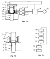
- Figure 1a discloses a cross section of a device 1 for determining and indicating if a fastening element 3 at fastening in a piece 5 has reached a tensile yield limit load.
- Figure 1 b discloses an enlargement of a part of the device 1 that is shown in figure 1a . The determination and the indication of the tensile yield limit occurs accordingly in real time during fastening of the fastening element 3.
- the fastening element 3 comprises a threaded shaft 7 that comprises a magnetostrictive material.
- the fastening element 3 can for example be a screw or similar threaded element.
- the threaded shaft 7 comprises a magnostrictive material, which material's magnetic properties are influenced by mechanical stress in the material.
- the magnetostrictive material comprises for example different alloys of iron or nickel.
- the fastening element 3 has a torsion head 8 in connection to the threaded shaft 7 for receiving a torsion force.
- the device 1 comprises means 9, 12 for generating an alternating magnetic field that penetrates the shaft 7 and the torsion head 8.
- the means for generating the alternating magnetic field comprises a first coil 9 that is provided with an alternating current from a first current supply unit 12.
- the first coil 9 is positioned around the torsion head 8 without being in contact with the torsion head 8.
- an air gap present located and an external torsion socket 13 is adapted to transfer a torsion force to the torsion head 8.
- the device 1 comprises means 9, 14 for measuring a physical quantity that depends on the momentary magnetic susceptibility of the shaft 7.
- the means for measuring the physical quantity comprises a sensor element adapted to be influenced by the alternating magnetic field.
- the sensor element is a coil, in this case the first coil 9.
- the first coil 9 is adapted to be exposed by the alternating magnetic field after the magnetic field's penetration of the shaft 7.
- the means for measuring the physical quantity comprises also a measuring unit 14 adapted to measure the physical quantity that arises in the first coil 9 after being exposed to the alternating magnetic field.
- the physical quantity is for example the inductance and the resistance of the first coil 9.
- the measuring unit 14 is adapted to measure the physical quantity based on the current that is being induced in the first coil 9 due to the alternating magnetic field.
- the means 9, 12 for generating the alternating magnetic field and the means 9, 14 for measuring the physical quantity is accordingly the same first coil 9.
- the means 9, 12 for generating the alternating magnetic field and the means 9, 14 for measuring the physical quantity are different coils.
- the device 1 comprises a control unit 16 adapted to receive measuring values of the physical quantity from the measuring unit 14.
- the control unit 16 is adapted to detect a significant change of the physical quantity based on the received measured values of the physical quantity.
- the control unit 16 is adapted, at a detection of the significant change, to determine and indicate if the shaft 7 of the fastening element 3 has reached the tensile yield limit load.
- the indication of the tensile yield limit load can for example be realized by means of an indication means 18, such as a lamp, a loud speaker or similar indication means 18.
- the device 1 comprises a torsion transfer unit 19 adapted to transfer a torsion force to the torsion head 8 of the fastening element 3.
- the torsion force is transferred by means of a torsion socket 13.
- the indication of a tensile yield limit load is realized by means of that the control unit 16 transmits a stop signal to the torsion transfer unit 19, wherein the transfer of the torsion force from the torsion transfer unit 19 to the torsion head 8 of the fastening element is interrupted.
- the indication of the tensile yield limit load is realized by means of that the control unit 16 transfers an indication signal to the torsion transfer unit 19, which indication signal induces the torsion transfer unit 19 to transfer a torsion force to the torsion head 8 of the fastening element 3 so that the load of the fastening element 3 is corrected with a certain correction value from the tensile yield limit load.
- the control unit 16 is accordingly adapted to control the torsion transfer unit's transfer of torsion force to the torsion head 8 of the fastening element 3 in dependency of an indication of a reached tensile yield limit load. Thereby, the control unit 16 is adapted to correct a reached tensile yield limit load with a certain correction value.
- the fastening element 3 can be corrected with the certain correction value from the tensile yield limit load so that the fastening element 3 resumes into the elastic state or so that the fastening element 3 enters into the plastic state.
- the device 1 comprises means 20, 22 for generating a static magnetic field that penetrates the shaft 7.
- the static magnetic field is for example generated by means of a second coil 20 that surrounds the torsion head 8 of the fastening element 3.
- the second coil 20 generates the static magnetic field by means of that a second current supply unit 22 provides the second coil 20 with a direct current.
- the second coil 20 is positioned around the first coil 9.
- the torsion head 8 extends in a plane that is mainly parallel with a surface of the piece 5.
- the first coil 9 is being essentially arranged in said plane.
- the second coil 20 is essentially arranged in the plane.
- the first coil 9 is adapted to receive an alternating current with a frequency between 1 Hz and 1 MHz, preferably between 28 Hz and 350 Hz, for generating the alternating magnetic field.
- an alternating current with a frequency between 1 Hz and 1 MHz, preferably between 28 Hz and 350 Hz, for generating the alternating magnetic field.
- the magnetic field can not penetrate the surface of the fastening element 3 due to the so called skin effect. Accordingly, it is not possible to detect a tensile yield limit load of the fastening element 3 at too high frequencies.
- Figure 1 c discloses a block diagram of a method for determining a tensile yield limit load at fastening of the fastening element 3. The method is adapted to be used continuously during fastening of the fastening element 3.
- Block 30 of the method comprises generating an alternating magnetic field that penetrates the shaft 7 of the fastening element 3.
- the magnetic field is influenced by the magnetostrictive properties of the shaft 7 of the fastening element 3.
- the method comprises measuring a physical quantity that depends on the momentary magnetic susceptibility of the shaft 7 of the fastening element 3.
- the physical quantity is for example the resistance or the inductance of the first coil 9.
- the method comprises detecting a significant change of the physical quantity.
- the detection of the significant change of the physical quantity is realized by means of identifying a mainly constant rate of change of the physical quantity in relation to the strain of the shaft 7 of the fastening element 3 and to identify a deviation from the mainly constant rate of change of the physical quantity.
- the detection of the significant change of the physical quantity is realized by means of detecting an absolute change of a physical quantity based on an initial value or an maximal value of the physical quantity.
- the method comprises determining if the shaft 7 of the fastening element has reached the tensile yield limit load based on the significant change of the physical quantity.
- the method comprises according to block 38 indicating that the tensile yield limit load has been reached.
- the indication comprises transferring an indication signal, which indication signal in block 40 initiates a correction of the load of the fastening element 3.
- the method is repeated from block 30. Accordingly, the method is adapted to be iterated until the tensile yield limit load is being indicated.
- Figure 2a , 2b , 3a and 3b discloses different embodiments of the control unit's 16 detection of the significant change of the physical quantity.
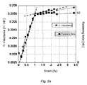
- Figure 2a discloses a diagram over the inverse of the inductance and the fastening force with the strain of the fastening element 3.
- the significant change of the physical quantity the inverse of the inductance is detected by means of identifying the mainly constant change of the inverse of the inductance in relation to the strain of the shaft 7 of the fastening element 3.
- the significant change of the physical quantity the inverse of the inductance is detected when a deviation from the mainly constant rate of change of the physical quantity the inverse of the inductance exceeds a first certain value.
- the continuous rate of change of the inverse of the inductance in relation to the strain is deviating and a new rate of change is initiated.
- the deviating rate of change is drawn with a dashed and dotted line which rate of change is slower than the initial identified rate of change.
- the deviating rate of change does not necessarily need to be continuous.
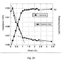
- figure 2b discloses a diagram where the physical quantity inductance in relation to the strain and the fastening force in relation to the strain is shown. The determination of the significant change of the physical quantity the inductance is realized in a corresponding way.
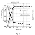
- Figure 3a discloses a diagram of the inductance and the fastening force with the strain of the fastening element 3.
- the significant change of the physical quantity the inductance is detected by means of identifying an absolute change of the inductance based on an initial value or a maximal value.
- the absolute change of the physical quantity the inductance from an initial value or a maximal value is dependent on the type of fastening element and tensile yield limit definition.
- FIG 3a the detection of the significant change is shown based on four different signal changes, marked with a, b, c, d, from an initial value to the tensile yield limit load Rp0.01 and Rp0.2 for a certain type of fastening element.
- the signal changes a and b the significant change of the physical quantity the inductance is based on an initial value of the physical quantity.
- the signal changes c and d the significant change of the inductance is based on a maximal value of the physical quantity.
- the tensile yield limit load such as Rp0.01 and Rp0.2.
- Rp0.01 and Rp0.2 the tensile yield limit load
- a and c the detection of the significant change of the physical quantity the inductance is realized for a tensile yield limit load of type Rp0.01.
- b and d the detection of the significant change of the physical quantity the inductance is realized for a tensile yield limit load of type Rp0.2.
- Figure 4 discloses a diagram that presents a dependency between torsion angle, fastening force and strain of the fastening element 3.
- the strain of the shaft 7 is determined based on a torsion of the fastening element 3 or a fastening installation element with a torsion angle.
- the torsion corresponds to a strain and an fastening force of the shaft 7 of the fastening element 3.
- the dependency between the torsion angle, the fastening force and the strain of the fastening element 3 depend on a threaded pitch of the threaded shaft or the fastening installation element.
- the fastening installation element is for example a bolt or similar element that at rotation is pressed towards the piece 5, which results in an increased stress of the shaft 7 of the fastening element 3.
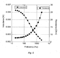
- Figure 5 discloses how the inductance and the resistance vary with the frequency when the coil 9 is positioned in connection to the fastening element 3.
- the coil 9 is positioned above the torsion head 8.
- the coil 9 generates an alternating magnetic field that influence the torsion head 8 and the shaft 7 of the fastening element 3, which torsion head 8 and shaft 7 in turn influence the inductance and the resistance of the coil 9.
- Figure 5 discloses accordingly the magnetic response from the fastening element 3 measured with the coil 9. At an increase in the frequency of the alternating magnetic field the resistance and the inductance of the coil 9 decrease, and vice verse.
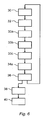
- Figure 6 discloses a block diagram over a method according to a second embodiment of the invention, which is suitable to use in such situations.
- the method differs from the method shown in fig. 1 c in that the method comprises the step of, in a block 33a, determining the strain of the shaft 7 of the fastening element 3.
- the strain of the shaft 7 can for example be determined based on a rotation of the fastening element 3 or a threaded fastening installation element, and a threaded pitch of said threaded shaft 7 or fastening installation element.
- the method further comprises the step, in a block 33b, identifying a mainly constant rate of change of the physical quantity in relation to the strain of the shaft 7 while fastening the fastening element 3.
- An example of establishment of constant rate of change is shown in fig. 7a and illustrated in the form of a first line L1.
- the method further comprises the step, in a block 33c, establishing a line L2 in the graph representing the strain on a first axis versus the physical quantity on a second axis, see fig. 7a .
- the line L2 is established so that the line L2 originates from the first axis at a certain offset strain, in fig. 7a 0,2% strain, and extending with the identified mainly constant rate of change of the physical quantity.
- the method further comprises the step, in a block 34a, detecting the significant change of the physical quantity relating to the tensile yield limit load of the fastening elements 3 when the measured physical quantity with the determined strain intersects the established line L2.
- the intersection is detected when a difference D1 between the measured physical quantity and the value of the physical quantity of the established line at the determined strain and the corresponding strain of the established line L2 is less than a second certain value C2.
- the tensile yield limit load can more reliable be detected in comparison to other ways of detecting the significant change. This is in particular of importance for fasting elements 3 that provide a weak response on the significant change of the physical quantity at the tensile yield limit load.
- Figure 7a discloses an example of a graph used for detecting the significant change relating to a tensile yield limit load of the method disclosed in fig. 6 .
- the first axis of the graph in this case the x-axis, represents the determined strain of the shaft 7.
- the second axis of the graph, in this case the y-axis represents the measured physical quantity the inverse inductance.
- the measurements of the inverse inductance and the determination of the strain of the shaft 7 are collected continuously during fasting the fasting element 3.
- the values of the measurements of the inverse inductance and the determination of the strain is plotted in the graph and is depicted as dots in the graph.
- a second line L2 is established, which second line L2 originates from the first axis with a certain offset strain, in this case 0,2% strain, and extends from the first axis with the established constant rate of change, i.e. the slope of the first line L1. Accordingly, the second line L2 has the same inclination as the first line L1.
- the significant change of the measured inverse inductance is detected when the difference D1 between the measured physical quantity at the determined strain and the value of the physical quantity of the established line L2 at the corresponding strain of the established line L2 is less than a second certain value C2, see fig. 7b disclosing an enlargement of a part of fig. 7a where the significant change is detected for the dot marked with an X and an error margin.
- the significant change is detected when the measured values of the inverse inductance with the strain intersects the established line L2 with the error margin.
- the magnetic susceptibility at low excitation frequencies, ⁇ can be described as inverse proportional to the magnetic anisotropy, K. This is in particular true for material with a susceptibility that has a low degree of influence with thermal variations.
- K K 0 + C ⁇ and where ⁇ is the mechanical stress in the fastening element 3, C is a constant that depends on the materials magnetostriction and K 0 is the magnetic anisotropy without added mechanical stress.
- the inductance for the coil system is proportional to the permeability of the magnetic material that is in close connection with the coil system.
- the permeability is about equal to the susceptibility, because ⁇ > > 1: L ⁇ ⁇ ⁇ X which results in that: L ⁇ ⁇ ⁇ 1 K ⁇ 1 K 0 + C ⁇ thus: 1 L ⁇ K 0 + C ⁇
- first current supply unit 12 and the second current supply unit 22 can be the same current supply unit.
- the torsion force is transmitted either by means of an external torsion socket 13, such as shown in figure 1 a and 1 b, or by means of an internal tool, such as a female screw tool.
- the means 9, 12 for generating the alternating magnetic field and the means 9, 14 for measuring the physical quantity is located either in a static condition or in a rotating condition together with a torsion transfer unit 13, 19 rotating the fastening element 3 or fastening installation element.
Landscapes
- Physics & Mathematics (AREA)
- General Physics & Mathematics (AREA)
- Chemical & Material Sciences (AREA)
- Analytical Chemistry (AREA)
- Engineering & Computer Science (AREA)
- Mechanical Engineering (AREA)
- Electromagnetism (AREA)
- Life Sciences & Earth Sciences (AREA)
- Health & Medical Sciences (AREA)
- Electrochemistry (AREA)
- Biochemistry (AREA)
- General Health & Medical Sciences (AREA)
- Immunology (AREA)
- Pathology (AREA)
- Chemical Kinetics & Catalysis (AREA)
- Force Measurement Appropriate To Specific Purposes (AREA)
- Investigating Strength Of Materials By Application Of Mechanical Stress (AREA)
- Investigating Or Analyzing Materials By The Use Of Magnetic Means (AREA)
- Details Of Spanners, Wrenches, And Screw Drivers And Accessories (AREA)
Description
- The present invention relates to a device and a method for indicating if a fastening element at fastening in a piece has reached a tensile yield limit load. The fastening element comprises a threaded shaft, which shaft comprises a magnetostrictive material.
- At fastening of the fastening element in the piece influence of friction between the fastening element and the piece results in that the stress in the fastening element only roughly can be estimated. If the fastening element is loaded to a too high stress the fastening element can be weakened or break. Due to the uncertainty in the stress of the fastening element, it is necessary to fastening the fastening element with a safety marginal to an optimal load. Accordingly, the fastening element is not used optimally, which results in that thicker dimensions or greater number of fastening elements is necessary. The thicker dimension of the fastening element or the greater number of fastening elements subsequent results in that the weight of a structure comprising the fastening element and the piece increases. In many application, it is important that the weight of the structure is limited. For example when fastening element is used in transport structures, such as cars, trains, aeroplanes, etcetera, an increased weight of the structure results in increased operation costs. It is also important that the fastening element is fasten with sufficient high stress for the structure to be held together in a safe manner.
- Known methods for measuring the stress in fastening elements is based on that an ultrasonic signal is sent by means of a transmitter from a torsion head of the fastening element to the end of the shaft of the fastening element, wherein the signal is reflected at the end of the shaft of the fastening element. The method has the disadvantage that the transmitter and the torsion head of the fastening element must be in physical contact with each other and that contact means, such as a gel or similar is necessary in order to obtain sufficient signal transferring. Thereby it is difficult to perform the measurement of the stress in the fastening element at a rotating state of the fastening element. Furthermore, it may be necessary to use special designed ends of the shaft of the fastening element in order to obtain sufficient signal response.
- A method for measuring a single axis tensile yield limit load of a shaft comprising a magnetostrictive material is known. The method is based on identifying a maximum of the magnetic susceptibility, which maximum corresponds to the single axis tensile yield limit load. The method is on the other hand not applicable to a multi axis stress condition for determining a tensile yield limit load, such as at fastening of a fastening element comprising tensile and torsion stresses, because the maximum of the magnetic susceptibility does not correspond to the multi axis tensile yield limit load.
- The document
JP56019423 - A first object of the present invention is to provide a device and a method for indicating if a fastening element at fastening in a piece has reached a tensile yield limit load. A second object of the present invention is to provide a device and a method for controlling the fastening of a fastened element in dependency of a tensile yield limit load. A third object of the present invention is to provide a device and a method for fastening a fastening element to an optimal load.
- The first object is achieved by means of a device according to the preamble of
claim 1 and being characterized in that the device comprises means for generating an alternating magnetic field that penetrates the shaft,
means for measuring a physical quantity that depends on the momentary magnetic susceptibility of the shaft, wherein the means for measuring the physical quantity is adapted to be exposed to said magnetic field after the magnetic field's penetration of the shaft,
a control unit adapted to receive measured values of said physical quantity and detect a significant change of the physical quantity, wherein the control unit is adapted to based on the significant change determined and indicate if the shaft of the fastening element has reached the tensile yield limit load. - The momentary magnetic susceptibility of the shaft is changed at a change of the stress in the shaft of the fastening element that comprises the magnetostrictive material. The generated magnetic field is influenced at penetration of the shaft by the momentary magnetic susceptibility of the shaft. The means for measuring the physical quantity is exposed to the magnetic field after its penetration of the shaft and is adapted to measure the physical quantity, which physical quantity depends on the momentary magnetic susceptibility of the shaft.
- The control unit is adapted to receive measured values of the physical quantity from the means for measuring the physical quantity and to detect the significant change of the physical quantity. The significant change of the physical quantity corresponds to the tensile yield limit load of the shaft of the fastening element. When detecting the significant change of the physical quantity the control unit is adapted to indicate that the fastening element has reached the tensile yield limit load.
- The term "tensile yield limit load" relates to the load when the material of the shaft of the fastening element transcends from an elastic state to a plastic state.
- The term "the momentary magnetic susceptibility", often denoted with the Greek letter X, relates to a material property that describes how magnetic a material becomes in an external magnetic field. For magnetostrictive materials, the momentary magnetic susceptibility is influenced by the stress in the material.
- The device has the advantage that no physical contact with the fastening element is necessary for indicating the tensile yield limit load. Thereby, the tensile yield limit load can be indicated during fastening of the fastening element in the piece. By means of the device, it is possible to avoid that the fastening element is being fastened to a load that results in a weakening or break of the fastening element. Moreover, the risk that the fastening element is fastened to a too low stress for holding together the structure is reduced.
- Based on the information on tensile yield limit load it is possible to optimize the fastening of the fastening element in the piece. Thereby, it is possible to reduce the weight of a structure comprising the fastening element and the piece. The device can be used on all types of fastening elements with a shaft that comprises a magnetostrictive material.
- According to an embodiment of the invention, the significant change of the physical quantity is detected in relation to a strain of the shaft.
- According to an embodiment of the invention, the strain of the shaft is determined based on a rotation of the fastening element or a threaded fastening installation element, and a threaded pitch of said threaded shaft or fastening installation element.
- The term "threaded pitch" relates to the degree of displacement of the shaft or the fastening installation element in axial direction at a certain rotation of the fastening element. The threaded pitch differs between different variants of fastening elements and different variants of fastening installation elements. The fastening installation element is for example a bolt or similar element that at a rotation influences the stress in the shaft of the fastening element.
- According to an embodiment of the invention, the control unit is adapted to identify a mainly constant rate of change of the physical quantity in relation to the strain of the shaft, wherein said significant change of the physical quantity is detected when a change from the mainly constant rate of change of the physical quantity exceeds a first certain value.
- The mainly constant rate of change of the physical quantity is present at least during a part of the elastic state until the tensile yield limit load of the fastening element. At the tensile yield limit load the significant change of the physical quantity arises, which change deviates from the mainly constant rate of change.
- According to an embodiment of the invention, the control unit is adapted to detect the significant change of the physical quantity when an absolute change of the physical quantity from any of an initial value or a maximal value has arisen.
- The significant change of the physical quantity at the tensile yield limit load based on the absolute change of the physical quantity is different for different variants of fastening elements, such as fastening elements with different strength, length, geometry, dimensions, etcetera.
- According to an embodiment of the invention, the fastening element is fastened with a constant or a mainly constant rotation speed, wherein the significant change of the physical quantity is detected in relation to the time for the fastening of the fastening element. The strain of the shaft of the fastening element at a constant rotation speed is dependent on the time of the fastening.
- According to an embodiment of the invention, the means for measuring the physical quantity is a sensor element adapted to be exposed to said magnetic field after the magnetic field's penetration of the shaft, wherein said physical quantity is at least one of a resistance and an inductance of the sensor element. The resistance and the inductance of the sensor element are dependent on the momentary magnetic susceptibility of the shaft.
- According to an embodiment of the invention, the sensor element is adapted to at least partly surround a torsion head of the fastening element while the torsion head is affected by a torsion force.
- According to an embodiment of the invention, the sensor element is an inductive component, such as a coil. The inductive component is adapted to at exposure of the alternating magnetic field induce an electrical current, which electrical current is being detected by the control unit.
- According to an embodiment of the invention, the means for generating the alternating magnetic field is adapted to receive an alternating electric current with a frequency between 1 Hz and 1 MHz, preferably between 28 Hz and 350 Hz, wherein said alternating magnetic field is being generated.
- According to an embodiment of the invention, the means for generating the alternating magnetic field is an inductive component, such as a coil, which inductive component is adapted to at least partly surround a torsion head of the fastening element while the torsion head is affected by a torsion force.
- According to one embodiment of the invention, the inductive component is a magnetic field sensor detecting the magnetic field based on one of the Hall-effect and the magnetoresistance of the sensor.
- According to an embodiment of the invention, the device comprises means for generating a static magnetic field that penetrates the shaft. By means of the static magnetic field the significant change of the physical quantity is enhanced, wherein the detection of the significant change of the physical quantity is facilitated.
- The second object of the invention is provided by an embodiment of the invention according to claim 11, wherein the device comprises a torsion transfer unit adapted to transfer a torsion force to the fastening element or a threaded fastening installation element, wherein the torsion transfer unit is adapted to by means of the control unit be controlled in dependency of an indication of a reached tensile yield limit load.
- According to an embodiment of the invention, the control unit is adapted to interrupt the torsion transfer unit transferring of the torsion force to the fastening element at an indication of a reached tensile yield limit load. Thereby, the fastening element is prevented from being loaded into the plastic state.
- According to an embodiment of the invention, the control unit is adapted to interrupt the torsion transfer unit's transferring of the torsion force to the fastening element at an indication of a tensile yield limit load according to the Rp0.2 limit.
- According to an embodiment of the invention, the control unit is adapted to store information of a reached tensile yield limit load for a specific fastening element.
- The third object of the invention is provided by an embodiment of the invention according to claim 12, wherein the torsion transfer unit is adapted to based on indication of a reached tensile yield limit load rotate the fastening element so that the load of the fastening element is corrected with a certain correction value.
- The tensile yield limit load is used as a reference for correcting the load of the fastening element in the piece with a certain correction value. By means of the correction, it is possible to load the fastening element with the certain correction value from the tensile yield limit load into the plastic state or with the certain correction value into the elastic state.
- According to an embodiment of the invention, the control unit is adapted to store information of said correction with the certain correction value from the tensile yield limit load for a specific fastening element.
- According to an embodiment of the invention, the control unit is adapted to receive measuring values for said physical quantity and store information of the physical quantity at a termination of the fastening of the fastening element. The fastening of the fastening element is terminated at the tensile yield limit load or after the correction of the stress of the fastening element with the certain correction value from the tensile yield limit load.
- According to an embodiment of the invention, the device is adapted, after terminated fastening of the fastening element, to generate an alternating magnetic field that penetrates the shaft of the fastening element by means of the means for generating the alternating magnetic field, measuring the physical quantity that depends on the momentary magnetic susceptibility of the shaft by means of the means for measuring the physical quantity, comparing the physical quantity at fastening of the fastening element with the physical quantity a time period after terminated fastening, and determining if the change of the physical quantity exceeds a certain control value by means of the control unit, wherein the control unit is adapted, when the physical quantity exceeds the certain control value for the change, to indicate that the change exceeds the certain control value.
- A time period after terminated fastening of the fastening element, such as a couple of months or years, the stress in the fastening element may decrease due to movements in the piece, the material in the piece or the fastening element yields, etcetera. By means of comparing the physical quantity that depends on the momentary magnetic susceptibility at termination of the fastening with the momentary magnetic susceptibility a time period after terminated fastening, it is possible to detect a change in the stress of the fastening element. Thereby, it is possible to detect fastening element that a time period after terminated fastening has not sufficient high stress.
- Previous mentioned object is also achieved by means of a method according to claim 12 to 15. The method according to 12 comprises the steps of
- generating an alternating magnetic field that penetrates the shaft,
- measuring a physical quantity that depends on the momentary magnetic susceptibility of the shaft,
- detecting a significant change of the physical quantity,
- determining if the shaft of the fastening element has reached the tensile yield limit load based on the significant change of the physical quantity, and
- indicating that the fastening element has reached the tensile yield limit load in dependency of said determination.
- According to an embodiment of the invention, the method comprises the steps of:
- identifying a mainly constant rate of change of the physical quantity in relation to a strain of the shaft, and
- detecting said significant change of the physical quantity when a deviation from the mainly constant rate of change of the physical quantity reaches or exceeds a first certain value.
- According to an embodiment of the invention, the method comprises the steps of:
- identifying an absolute change of the physical quantity from any of an initial value or a maximal value of said physical quantity,
- detecting said significant change of the physical quantity when the absolute change of the physical quantity reached a first certain value.
- According to one embodiment of the invention, the method comprises:
- determining the strain of the shaft,
- identifying a mainly constant rate of change of the physical quantity in relation to an increased strain of the shaft,
- establishing a line in a graph representing the strain on a first axis versus the physical quantity on a second axis so that the line originates from a certain offset strain value at the first axis and extends with said identified constant rate of change,
- detecting said significant change of the physical quantity when the measured physical quantity intersects the established line with a certain error margin, and
- indicating that the fastening element has reached the offset tensile yield limit load if the measured physical quantity intersects the established line with the certain error margin.
- In some situation, the tensile yield limit load is difficult to determine from the shape of the stress-strain curve due to that the yield point is not well defined. In such situation, the tensile yield limit load may be defined based on the constant rate of change of the physical quantity, preferably the inductance, in relation to the offset strain, such as 0,1 or 0,2 % strain. The significant change is detected when a point of the measured physical quantity with the determined strain intersects the established line in the graph representing the strain versus the physical quantity.
- The intersection of the measured physical quantity with the determined strain is detected with an error margin corresponding to that the difference between the measured physical quantity at the determined strain and the physical quantity of the established line at the corresponding strain of the line is less than the second certain value.
- The determination of the significant change using the offset strain provides an improved reliability in determining and indicating that the fastening element has reached the tensile yield limit load in comparison to a deviation from a the mainly constant rate of change of the physical quantity.
- The term "constant rate of change" refers to the slope of the values of measurements of the physical quantity with the determined strain.
- According to one embodiment of the invention, the method comprises:
- detecting said significant change of the physical quantity when a difference between the measured physical quantity at the determined strain and the value of the physical quantity of the established line at the corresponding strain of the established line is less than a second certain value, and
- indicating that the fastening element has reached the offset tensile yield limit load if said difference is less than the second certain value.
- According to one embodiment of the invention, the method comprises:
- detecting said significant change of the physical quantity when a difference between the strain of the measured physical quantity and the value of the physical quantity of the established line at the corresponding value of the established line is less than a third certain value, and
- indicating that the fastening element has reached the offset tensile yield limit load if said difference is less than the third certain value.
- According to one embodiment of the invention, the method comprises:
- determining the strain of the shaft based on a rotation of the fastening element or a threaded fastening installation element, and a threaded pitch of said threaded shaft or fastening installation element.
- According to one embodiment of the invention, the method comprises:
- terminating the fastening of the fastening element in dependency of an indication that the fastening element has reached the tensile yield limit load.
- According to an embodiment of the invention the method comprises the steps of:
- rotating the fastening element based on an indication of a reached tensile yield limit load so that the load of the fastening element is corrected with a certain correction value.
- The invention will now be explained in detail with description of different embodiments of the invention and with reference to the appended drawings.
-
Figure 1 a discloses an device according to an embodiment of the invention. -
Figure 1 b discloses an enlargement of a part of the device that is disclosed infigure 1a . -
Figure 1 c discloses a block diagram over a method according to a first embodiment of the invention. -
Figure 2a discloses an example of a diagram for detecting a significant change of a physical quantity based on the inverse of the inductance. -
Figure 2b discloses an example of a diagram for detecting a significant change of a physical quantity based on the inductance. -
Figure 3a discloses an example of a diagram for detecting a significant change of a physical quantity based on the inductance. -
Figure 3b discloses a further example for detecting a significant change of the physical quantity based on the resistance. -
Figure 4 discloses a diagram that indicates a dependency between torsion angle, fastening force and strain of a fastening element. -
Figure 5 discloses a diagram that indicates a dependency between inductance and resistance of a coil with frequency of an alternating magnetic field. -
Figure 6 discloses a block diagram over a method according to a second embodiment of the invention. -
Figure 7a discloses an example of a diagram for detecting a significant change based on the inductance and an offset strain. -
Figure 7b discloses an enlargement of a part offig. 7a where the significant change is detected. -
Figure 1a discloses a cross section of adevice 1 for determining and indicating if afastening element 3 at fastening in apiece 5 has reached a tensile yield limit load.Figure 1 b discloses an enlargement of a part of thedevice 1 that is shown infigure 1a . The determination and the indication of the tensile yield limit occurs accordingly in real time during fastening of thefastening element 3. - The
fastening element 3 comprises a threadedshaft 7 that comprises a magnetostrictive material. Thefastening element 3 can for example be a screw or similar threaded element. The threadedshaft 7 comprises a magnostrictive material, which material's magnetic properties are influenced by mechanical stress in the material. The magnetostrictive material comprises for example different alloys of iron or nickel. Thefastening element 3 has atorsion head 8 in connection to the threadedshaft 7 for receiving a torsion force. - The
device 1 comprisesmeans 9, 12 for generating an alternating magnetic field that penetrates theshaft 7 and thetorsion head 8. In the disclosed embodiment in the figure, the means for generating the alternating magnetic field comprises afirst coil 9 that is provided with an alternating current from a first current supply unit 12. Thefirst coil 9 is positioned around thetorsion head 8 without being in contact with thetorsion head 8. Between thefirst coil 9 and thetorsion head 8 is an air gap present located and anexternal torsion socket 13 is adapted to transfer a torsion force to thetorsion head 8. - The
device 1 comprisesmeans shaft 7. The means for measuring the physical quantity comprises a sensor element adapted to be influenced by the alternating magnetic field. Infigure 1 a and 1b, the sensor element is a coil, in this case thefirst coil 9. Thefirst coil 9 is adapted to be exposed by the alternating magnetic field after the magnetic field's penetration of theshaft 7. The means for measuring the physical quantity comprises also a measuringunit 14 adapted to measure the physical quantity that arises in thefirst coil 9 after being exposed to the alternating magnetic field. The physical quantity is for example the inductance and the resistance of thefirst coil 9. The measuringunit 14 is adapted to measure the physical quantity based on the current that is being induced in thefirst coil 9 due to the alternating magnetic field. - In the disclosed embodiment, the
means 9, 12 for generating the alternating magnetic field and themeans first coil 9. In another embodiment, themeans 9, 12 for generating the alternating magnetic field and themeans - The
device 1 comprises acontrol unit 16 adapted to receive measuring values of the physical quantity from the measuringunit 14. Thecontrol unit 16 is adapted to detect a significant change of the physical quantity based on the received measured values of the physical quantity. Thecontrol unit 16 is adapted, at a detection of the significant change, to determine and indicate if theshaft 7 of thefastening element 3 has reached the tensile yield limit load. The indication of the tensile yield limit load can for example be realized by means of an indication means 18, such as a lamp, a loud speaker or similar indication means 18. - The
device 1 comprises atorsion transfer unit 19 adapted to transfer a torsion force to thetorsion head 8 of thefastening element 3. The torsion force is transferred by means of atorsion socket 13. - According to an embodiment of the invention, the indication of a tensile yield limit load is realized by means of that the
control unit 16 transmits a stop signal to thetorsion transfer unit 19, wherein the transfer of the torsion force from thetorsion transfer unit 19 to thetorsion head 8 of the fastening element is interrupted. In another embodiment, the indication of the tensile yield limit load is realized by means of that thecontrol unit 16 transfers an indication signal to thetorsion transfer unit 19, which indication signal induces thetorsion transfer unit 19 to transfer a torsion force to thetorsion head 8 of thefastening element 3 so that the load of thefastening element 3 is corrected with a certain correction value from the tensile yield limit load. - The
control unit 16 is accordingly adapted to control the torsion transfer unit's transfer of torsion force to thetorsion head 8 of thefastening element 3 in dependency of an indication of a reached tensile yield limit load. Thereby, thecontrol unit 16 is adapted to correct a reached tensile yield limit load with a certain correction value. Thefastening element 3 can be corrected with the certain correction value from the tensile yield limit load so that thefastening element 3 resumes into the elastic state or so that thefastening element 3 enters into the plastic state. - The
device 1 comprises means 20, 22 for generating a static magnetic field that penetrates theshaft 7. The static magnetic field is for example generated by means of asecond coil 20 that surrounds thetorsion head 8 of thefastening element 3. Thesecond coil 20 generates the static magnetic field by means of that a secondcurrent supply unit 22 provides thesecond coil 20 with a direct current. Thesecond coil 20 is positioned around thefirst coil 9. - The
torsion head 8 extends in a plane that is mainly parallel with a surface of thepiece 5. Thefirst coil 9 is being essentially arranged in said plane. In the same way, thesecond coil 20 is essentially arranged in the plane. Thereby, the generated alternating magnetic field and the static magnetic field penetrates theshaft 7 of thefastening element 3. - The
first coil 9 is adapted to receive an alternating current with a frequency between 1 Hz and 1 MHz, preferably between 28 Hz and 350 Hz, for generating the alternating magnetic field. At a too high frequency of the generated alternating magnetic field the magnetic field can not penetrate the surface of thefastening element 3 due to the so called skin effect. Accordingly, it is not possible to detect a tensile yield limit load of thefastening element 3 at too high frequencies. -
Figure 1 c discloses a block diagram of a method for determining a tensile yield limit load at fastening of thefastening element 3. The method is adapted to be used continuously during fastening of thefastening element 3. -
Block 30 of the method comprises generating an alternating magnetic field that penetrates theshaft 7 of thefastening element 3. Thereby, the magnetic field is influenced by the magnetostrictive properties of theshaft 7 of thefastening element 3. - In
block 32 the method comprises measuring a physical quantity that depends on the momentary magnetic susceptibility of theshaft 7 of thefastening element 3. The physical quantity is for example the resistance or the inductance of thefirst coil 9. - In
block 34 the method comprises detecting a significant change of the physical quantity. In an embodiment of the method, the detection of the significant change of the physical quantity is realized by means of identifying a mainly constant rate of change of the physical quantity in relation to the strain of theshaft 7 of thefastening element 3 and to identify a deviation from the mainly constant rate of change of the physical quantity. In another embodiment of the method, the detection of the significant change of the physical quantity is realized by means of detecting an absolute change of a physical quantity based on an initial value or an maximal value of the physical quantity. - In
block 36 the method comprises determining if theshaft 7 of the fastening element has reached the tensile yield limit load based on the significant change of the physical quantity. At a determination that thefastening element 3 has reached the tensile yield limit load, the method comprises according to block 38 indicating that the tensile yield limit load has been reached. - According to an embodiment of the invention the indication comprises transferring an indication signal, which indication signal in
block 40 initiates a correction of the load of thefastening element 3. - At lack of a determination of a reached tensile yield limit load, the method is repeated from
block 30. Accordingly, the method is adapted to be iterated until the tensile yield limit load is being indicated. -
Figure 2a ,2b ,3a and3b discloses different embodiments of the control unit's 16 detection of the significant change of the physical quantity. -
Figure 2a discloses a diagram over the inverse of the inductance and the fastening force with the strain of thefastening element 3. Infigure 2a , the significant change of the physical quantity the inverse of the inductance is detected by means of identifying the mainly constant change of the inverse of the inductance in relation to the strain of theshaft 7 of thefastening element 3. The significant change of the physical quantity the inverse of the inductance is detected when a deviation from the mainly constant rate of change of the physical quantity the inverse of the inductance exceeds a first certain value. - In
figure 2a the continuous rate of change of the inverse of the inductance in relation to the strain from about 0.3 % strain up to about 1.0 % strain is seen. The continuous rate of change is represented by means of a dotted line. The continuous rate of change corresponds with the continuous rate of change of the fastening force in relation to the strain when thefastening element 3 is present in the elastic state. - At about one percent strain the continuous rate of change of the inverse of the inductance in relation to the strain is deviating and a new rate of change is initiated. The deviating rate of change is drawn with a dashed and dotted line which rate of change is slower than the initial identified rate of change. The deviating rate of change does not necessarily need to be continuous.
- In
figure 2a the fastening force in relation to the strain is also drawn. It can be seen that the deviation of the mainly constant rate of change of the inverse of the inductance corresponds with the transition from an elastic state to a plastic state, that is the tensile yield limit load for thefastening element 3. - In the same manner as in
figure 2a ,figure 2b discloses a diagram where the physical quantity inductance in relation to the strain and the fastening force in relation to the strain is shown. The determination of the significant change of the physical quantity the inductance is realized in a corresponding way. -
Figure 3a discloses a diagram of the inductance and the fastening force with the strain of thefastening element 3. Infigure 3a the significant change of the physical quantity the inductance is detected by means of identifying an absolute change of the inductance based on an initial value or a maximal value. - The absolute change of the physical quantity the inductance from an initial value or a maximal value is dependent on the type of fastening element and tensile yield limit definition. In
figure 3a the detection of the significant change is shown based on four different signal changes, marked with a, b, c, d, from an initial value to the tensile yield limit load Rp0.01 and Rp0.2 for a certain type of fastening element. For the signal changes a and b, the significant change of the physical quantity the inductance is based on an initial value of the physical quantity. For the signal changes c and d, the significant change of the inductance is based on a maximal value of the physical quantity. - There are different definitions of the tensile yield limit load, such as Rp0.01 and Rp0.2. For the signal changes a and c the detection of the significant change of the physical quantity the inductance is realized for a tensile yield limit load of type Rp0.01. For signal changes b and d the detection of the significant change of the physical quantity the inductance is realized for a tensile yield limit load of type Rp0.2.
- In the same way as shown in
figure 3b , a detection of the significant change of the physical quantity the resistance in relation to strain is shown. The detestation of the significant change of the physical quantity the resistance is realized from an initial value of the physical quantity the resistance for the signal changes a' and b', and from a minimum value of the physical quantity the resistance for the signal changes c' and d'. The detection of the significant change of the physical quantity the resistance is realized in a corresponding way to the determination according tofigure 3a . -
Figure 4 discloses a diagram that presents a dependency between torsion angle, fastening force and strain of thefastening element 3. The strain of theshaft 7 is determined based on a torsion of thefastening element 3 or a fastening installation element with a torsion angle. - The torsion corresponds to a strain and an fastening force of the
shaft 7 of thefastening element 3. The dependency between the torsion angle, the fastening force and the strain of thefastening element 3 depend on a threaded pitch of the threaded shaft or the fastening installation element. The fastening installation element, not disclosed in the figure, is for example a bolt or similar element that at rotation is pressed towards thepiece 5, which results in an increased stress of theshaft 7 of thefastening element 3. -
Figure 5 discloses how the inductance and the resistance vary with the frequency when thecoil 9 is positioned in connection to thefastening element 3. For example, thecoil 9 is positioned above thetorsion head 8. Thecoil 9 generates an alternating magnetic field that influence thetorsion head 8 and theshaft 7 of thefastening element 3, whichtorsion head 8 andshaft 7 in turn influence the inductance and the resistance of thecoil 9.Figure 5 discloses accordingly the magnetic response from thefastening element 3 measured with thecoil 9. At an increase in the frequency of the alternating magnetic field the resistance and the inductance of thecoil 9 decrease, and vice verse. - An electrical impedance of the
coil 9 in vicinity of thefastening element 3, for example at thetorsion head 8 of thefastening element 3, is being measured. The electrical impedance of thecoil 9 can be described as z(f)=R(f)+jωL, where R is the electrical resistance that in turn depends on the magnetic losses in thefastening element 3, thepiece 5 and thetorsion socket 13, L is the inductance with magnetic response in phase with the excitation of thefastening element 3, thepiece 5 and thetorsion socket 13, and ω = 2πf, where f is the excitation frequency in thecoil 9, the alternating magnetic field from thecoil 9 is used for measuring the impedance of thecoil 9 in a specific frequency interval from a couple of Hz to several kHz and has a constant excitation amplitude of about 0.1 mT and with direction that corresponds with the direction of the mechanical stress (strain) that is to be measured. A typical measurement of L and R as a function of frequency when thecoil 9 is being arranged in vicinity of thefastening element 3, thetorsion socket 13 and thepiece 5 is shown infigure 5 . - For certain materials of the
fastening element 3, it is difficult to determine the tensile yield point based on a deviation of the constant rate of change of the physical quantity at the tensile yield point.Figure 6 discloses a block diagram over a method according to a second embodiment of the invention, which is suitable to use in such situations. - The method differs from the method shown in
fig. 1 c in that the method comprises the step of, in ablock 33a, determining the strain of theshaft 7 of thefastening element 3. The strain of theshaft 7 can for example be determined based on a rotation of thefastening element 3 or a threaded fastening installation element, and a threaded pitch of said threadedshaft 7 or fastening installation element. - The method further comprises the step, in a
block 33b, identifying a mainly constant rate of change of the physical quantity in relation to the strain of theshaft 7 while fastening thefastening element 3. An example of establishment of constant rate of change is shown infig. 7a and illustrated in the form of a first line L1. - When fastening the
fastening element 3 the strain in theshaft 3 of thefastening element 3 gradually increases. Thus, during fasting of thefasting element 3 values on the physical quantity with the strain are collected and saved in a memory unit of thecontrol unit 16. The mainly constant rate of change of the physical quantity is identified by for example finding an average of the collected values, which average is illustrated with the first line L1. - The method further comprises the step, in a
block 33c, establishing a line L2 in the graph representing the strain on a first axis versus the physical quantity on a second axis, seefig. 7a . The line L2 is established so that the line L2 originates from the first axis at a certain offset strain, infig. 0,2% strain, and extending with the identified mainly constant rate of change of the physical quantity.7a - The method further comprises the step, in a
block 34a, detecting the significant change of the physical quantity relating to the tensile yield limit load of thefastening elements 3 when the measured physical quantity with the determined strain intersects the established line L2. The intersection is detected when a difference D1 between the measured physical quantity and the value of the physical quantity of the established line at the determined strain and the corresponding strain of the established line L2 is less than a second certain value C2. - By means of using the offset strain value, identifying a constant rate of change of the physical quantity with the strain, establishing the line L2 comprising the identified constant rate of change and finding the intersection of the measurements with the established line, the tensile yield limit load can more reliable be detected in comparison to other ways of detecting the significant change. This is in particular of importance for
fasting elements 3 that provide a weak response on the significant change of the physical quantity at the tensile yield limit load. -
Figure 7a discloses an example of a graph used for detecting the significant change relating to a tensile yield limit load of the method disclosed infig. 6 . The first axis of the graph, in this case the x-axis, represents the determined strain of theshaft 7. The second axis of the graph, in this case the y-axis, represents the measured physical quantity the inverse inductance. - The measurements of the inverse inductance and the determination of the strain of the
shaft 7 are collected continuously during fasting thefasting element 3. The values of the measurements of the inverse inductance and the determination of the strain is plotted in the graph and is depicted as dots in the graph. - After sufficient values of the inverse inductance with the strain have been collected, a constant rate of change is established. In
fig. 7a , the constant rate of change is established based on the encircled dots in the graph and illustrated by the first line L1. - After that the constant rate of change has been established, a second line L2 is established, which second line L2 originates from the first axis with a certain offset strain, in this
case - The significant change of the measured inverse inductance is detected when the difference D1 between the measured physical quantity at the determined strain and the value of the physical quantity of the established line L2 at the corresponding strain of the established line L2 is less than a second certain value C2, see
fig. 7b disclosing an enlargement of a part offig. 7a where the significant change is detected for the dot marked with an X and an error margin. Thus, the significant change is detected when the measured values of the inverse inductance with the strain intersects the established line L2 with the error margin. - The magnetic susceptibility at low excitation frequencies, χ can be described as inverse proportional to the magnetic anisotropy, K. This is in particular true for material with a susceptibility that has a low degree of influence with thermal variations.
- For a material the following relation is present:


fastening element 3, C is a constant that depends on the materials magnetostriction and K0 is the magnetic anisotropy without added mechanical stress. The inductance for the coil system is proportional to the permeability of the magnetic material that is in close connection with the coil system. - The permeability is about equal to the susceptibility, because χ > > 1:


- Accordingly, if 1/L is plotted with the strain the strain curve for the fastening element is reflected provided that the surrounding magnetic material is not being deformed during the torsion, such as the
torsion socket 13 or thepiece 5. - The invention is not limited to the disclosed embodiments but can be modified and varied within the framework for the following claims.
- For example the first current supply unit 12 and the second
current supply unit 22 can be the same current supply unit. The torsion force is transmitted either by means of anexternal torsion socket 13, such as shown infigure 1 a and 1 b, or by means of an internal tool, such as a female screw tool. - The
means 9, 12 for generating the alternating magnetic field and themeans torsion transfer unit fastening element 3 or fastening installation element.
Claims (12)
- Device (1) for indicating if a fastening element (3) at fastening in a piece (5) has reached a tensile yield limit load, wherein the fastening element (3) comprises a threaded shaft (7), which shaft (7) comprises a magnostrictive material, the device (1) comprises:- means (9, 12) for generating an alternating magnetic field that penetrates the shaft (7),- means (9, 14) for measuring a physical quantity,- a control unit (16) adapted to receive measured values of said physical quantity,characterized in thatthe means for measuring the physical quantity (9, 14) comprises a sensor element (9) adapted to be exposed to said magnetic field after the magnetic field's penetration of the shaft (7), wherein said physical quantity is at least one of a resistance and an inductance of the sensor element (9) that depend on the momentary magnetic susceptibility of the shaft (7), wherein the control unit (16) is adapted to identify:1a) a mainly constant rate of change of the physical quantity in relation to a strain of the shaft (7), or1b) any of an initial value or a maximal value of the physical quantity in relation to a strain of the shaft (7),and detect a significant change of the physical quantity corresponding to:2a) a deviation from the mainly constant rate of change of the physical quantity exceeds a first certain value, or2b) an absolute change of the physical quantity from any of an initial value or a maximal value,and on basis of the significant change determine and indicate if the shaft (7) of the fastening element (3) has reached the tensile yield limit load.
- Device (1) according to claim 1, characterized in that the means for generating the alternating magnetic field is adapted to receive an alternating electric current with a frequency between 28 Hz and 350 Hz, wherein said alternating magnetic field is being generated.
- Device (1) according to any of claim 1 and 2, characterized in that the strain of the shaft (7) is determined based on a rotation of the fastening element (3) or a threaded fastening installation element, and a threaded pitch of said threaded shaft (7) or fastening installation element.
- Device (1) according to any of the previous claims, characterized in that the sensor element (9) is adapted to at least partly surround a torsion head (8) of the fastening element (3) while the torsion head (8) is influenced by a torsion force.
- Device (1) according to any of the previous claims, characterized in that the means (9, 12) for generating the alternating magnetic field comprises an inductive component (9), which inductive component (9) is adapted to at least partly surround a torsion head (8) of the fastening element (3) while the torsion head (8) is affected by a torsion force.
- Device (1) according to any of the previous claims, characterized in that the device (1) comprises means (20, 22) for generating a static magnetic field that penetrates the shaft (7).
- Device (1) according to any of the previous claims, characterized in that the device (1) comprises a torsion transfer unit (13, 19) adapted to transfer a torsion force to the fastening element (3) or a threaded fastening installation element, wherein the torsion transfer unit (13, 19) is adapted, by means of the control unit (16), to be controlled in dependency of a reached tensile yield limit load.
- Device (1) according to claim 7, characterized in that the torsion transfer unit (13, 19) is adapted, based on the indication of a reached tensile yield limit load, to rotate the fastening element (3) so that the load of the fastening element (3) is corrected with a certain correction value.
- Method for indicating if a fastening element (3) at fastening in a piece (5) has reached a tensile yield limit load, wherein the fastening element (3) comprises a threaded shaft (7), which shaft (7) comprises a magnetostrictive material, wherein the method comprises the steps of:- generating an alternating magnetic field that penetrates the shaft (7),- measuring a physical quantity comprising at least one of a resistance and an inductance that depend on the momentary magnetic susceptibility of the shaft (7),- detecting a significant change of the physical quantity by identifying:1a) a mainly constant rate of change of the physical quantity in relation to a strain of the shaft (7), or1b) any of an initial value or a maximal value of the physical quantity in relation to a strain of the shaft (7),- detecting a significant change of the physical quantity corresponding to:2a) a deviation from the mainly constant rate of change of the physical quantity exceeds a first certain value, or2b) an absolute change of the physical quantity from any of an initial value or a maximal value,- determining if the shaft (7) of the fastening element (3) has reached the tensile yield limit load based on the significant change of the physical quantity, and- indicating that the fastening element (3) has reached the tensile yield limit load in dependency of said determination.
- Method according to claim 9, wherein the means for generating the alternating magnetic field receives an alternating electric current with a frequency between 28 Hz and 350 Hz, wherein said alternating magnetic field is being generated.
- Method according to any of claim 9 and 10, wherein the method comprises:- identifying a mainly constant rate of change of the physical quantity in relation to an increased strain of the shaft (7),- establishing a line (L2) in a graph representing the strain on a first axis versus the physical quantity on a second axis so that the line (L2) originates from a certain offset strain value at the first axis and extends with said identified constant rate of change,- detecting said significant change of the physical quantity when the measured physical quantity intersects the established line (L2) with a certain error margin, and- indicating that the fastening element (3) has reached the offset tensile yield limit load if the measured physical quantity intersects the established line (L2) with the certain error margin.
- Method according to any of claim 9-11, wherein the method comprises:- rotating the fastening element (3) based on an indication of a reached tensile yield limit load so that the load of the fastening element (3) is corrected with a certain correction value.
Applications Claiming Priority (2)
| Application Number | Priority Date | Filing Date | Title |
|---|---|---|---|
| SE1050589A SE1050589A1 (en) | 2010-06-08 | 2010-06-08 | Device and method for indicating whether a fastening element when fastened in one piece has reached a tensile limit load |
| PCT/EP2011/059491 WO2011154446A1 (en) | 2010-06-08 | 2011-06-08 | Device and method for indicating if a fastening element has reached a tensile yield limit load. |
Publications (2)
| Publication Number | Publication Date |
|---|---|
| EP2580562A1 EP2580562A1 (en) | 2013-04-17 |
| EP2580562B1 true EP2580562B1 (en) | 2016-03-23 |
Family
ID=44628060
Family Applications (1)
| Application Number | Title | Priority Date | Filing Date |
|---|---|---|---|
| EP11729935.4A Active EP2580562B1 (en) | 2010-06-08 | 2011-06-08 | Device and method for indicating if a fastening element has reached a tensile yield limit load. |
Country Status (7)
| Country | Link |
|---|---|
| US (1) | US8910526B2 (en) |
| EP (1) | EP2580562B1 (en) |
| JP (1) | JP5858493B2 (en) |
| KR (1) | KR101877072B1 (en) |
| CN (1) | CN102918371B (en) |
| SE (1) | SE1050589A1 (en) |
| WO (1) | WO2011154446A1 (en) |
Cited By (2)
| Publication number | Priority date | Publication date | Assignee | Title |
|---|---|---|---|---|
| DE102022122172A1 (en) | 2022-09-01 | 2024-03-07 | Adolf Würth GmbH & Co. KG | Fastening element with measuring device for determining a mechanical load condition by evaluating a frequency spectrum |
| WO2024175701A1 (en) | 2023-02-23 | 2024-08-29 | Rise Research Institutes of Sweden AB | Device and method for mechanical stress measurements |
Families Citing this family (10)
| Publication number | Priority date | Publication date | Assignee | Title |
|---|---|---|---|---|
| US20130114994A1 (en) | 2011-11-04 | 2013-05-09 | Robert Erik Grip | Truss end pad fitting |
| US9574587B2 (en) * | 2011-11-04 | 2017-02-21 | The Boeing Company | Preloading a fastener of a mechanical fitting |
| US8960012B2 (en) * | 2012-10-30 | 2015-02-24 | Jentek Sensors, Inc. | Method and apparatus for detection and characterization of mechanical damage |
| KR101985557B1 (en) * | 2014-07-15 | 2019-06-04 | 현대중공업 주식회사 | Mehtod for measuring pressure of enging's combusttion chamber |
| US10850375B2 (en) * | 2016-06-03 | 2020-12-01 | Atlas Copco Industrial Technique Ab | Clamp force estimation via pulsed tightening |
| CH712564A1 (en) * | 2016-06-07 | 2017-12-15 | Rego-Fix Ag | Clamping device for clamping a tool in a tool holder. |
| CN106500882B (en) * | 2016-10-13 | 2019-07-02 | 中海石油(中国)有限公司 | A bolt stress detection device |
| US10746704B2 (en) * | 2018-01-05 | 2020-08-18 | Vibrant Corporation | Use of resonance inspection for process control |
| CN114689233B (en) * | 2022-03-21 | 2024-03-08 | 中国航天标准化研究所 | A method for determining the installation torque of threaded fasteners |
| DE102023206067A1 (en) | 2023-06-28 | 2025-01-02 | Robert Bosch Gesellschaft mit beschränkter Haftung | preload measuring device |
Family Cites Families (23)
| Publication number | Priority date | Publication date | Assignee | Title |
|---|---|---|---|---|
| JPS537910A (en) | 1976-07-08 | 1978-01-24 | Kajima Corp | Prefabricating construction method |
| ZA774188B (en) * | 1976-08-09 | 1979-05-30 | Rockwell International Corp | Tension control of fasteners |
| JPS5619423A (en) * | 1979-07-27 | 1981-02-24 | Toshiba Corp | Bolt axial force detector |
| JPS6133871A (en) * | 1984-07-25 | 1986-02-17 | 滋賀ボルト株式会社 | Method of detecting load bearing point |
| DE3544920A1 (en) * | 1985-12-19 | 1987-06-25 | Kloeckner Humboldt Deutz Ag | Device for determining the initial stressing force of a long anti-fatigue bolt by means of a standing wave |
| EP0491002B1 (en) * | 1989-09-05 | 1994-02-23 | STENGEL, Wolfgang, Dr. | Process and device for non-destructive determination of the prestressing condition of ferromagnetic securing elements |
| CH680576A5 (en) * | 1990-05-31 | 1992-09-30 | Kistler Instrumente Ag | |
| US5154242A (en) * | 1990-08-28 | 1992-10-13 | Matsushita Electric Works, Ltd. | Power tools with multi-stage tightening torque control |
| FR2677571B1 (en) * | 1991-06-14 | 1995-08-04 | Ciandar | PROCESS FOR CONTROLLING AND CONTROLLING THE VOLTAGE OF A THREADED MEMBER. |
| SE9102121D0 (en) * | 1991-07-08 | 1991-07-08 | Skf Nova Ab | SENSOR SYSTEM |
| US5877432A (en) * | 1996-11-26 | 1999-03-02 | The University Of Dayton | Magnetostrictive actuator |
| JP2001324396A (en) * | 2000-05-12 | 2001-11-22 | Magnegraph:Kk | Inspection of bolt tightening |
| US6467355B1 (en) * | 2001-04-16 | 2002-10-22 | Irving Leong | Most accurate method of tensioning threaded fasteners in assembled units |
| WO2002095346A1 (en) * | 2001-05-21 | 2002-11-28 | Sensor System Co., Ltd. | Bolting tester |
| JP2003056397A (en) * | 2001-08-20 | 2003-02-26 | Yamaha Motor Co Ltd | Cylinder pressure measurement device for internal combustion engine |
| DE10217283B4 (en) * | 2002-04-12 | 2005-10-13 | Fraunhofer-Gesellschaft zur Förderung der angewandten Forschung e.V. | Device for setting and checking the clamping force of screwed connections |
| CN101660739B (en) | 2005-04-08 | 2012-01-18 | 东芝照明技术株式会社 | Lamp |
| US7484427B2 (en) * | 2006-06-06 | 2009-02-03 | Bolt Bethel, Llc | Adjustable torque thread gauge assembly and method of calibration thereof |
| JP5091555B2 (en) | 2007-06-22 | 2012-12-05 | 本田技研工業株式会社 | Magnetostrictive torque sensor and electric power steering apparatus |
| US7730784B2 (en) * | 2007-08-03 | 2010-06-08 | The Boeing Company | Ultrasonic method to verify the interference fit of fasteners |
| JP5163271B2 (en) * | 2008-05-13 | 2013-03-13 | マツダ株式会社 | Bolt fastening method and apparatus |
| JP4605307B1 (en) * | 2010-04-05 | 2011-01-05 | センサ・システム株式会社 | Bolt tightening force inspection device |
| US8534132B1 (en) * | 2010-11-19 | 2013-09-17 | Charles L. Purdy | Method for measuring tension in an anchored rod at an accessible end |
-
2010
- 2010-06-08 SE SE1050589A patent/SE1050589A1/en unknown
-
2011
- 2011-06-08 EP EP11729935.4A patent/EP2580562B1/en active Active
- 2011-06-08 KR KR1020137000286A patent/KR101877072B1/en active Active
- 2011-06-08 JP JP2013513677A patent/JP5858493B2/en active Active
- 2011-06-08 WO PCT/EP2011/059491 patent/WO2011154446A1/en not_active Ceased
- 2011-06-08 US US13/701,524 patent/US8910526B2/en active Active
- 2011-06-08 CN CN201180026791.XA patent/CN102918371B/en active Active
Cited By (2)
| Publication number | Priority date | Publication date | Assignee | Title |
|---|---|---|---|---|
| DE102022122172A1 (en) | 2022-09-01 | 2024-03-07 | Adolf Würth GmbH & Co. KG | Fastening element with measuring device for determining a mechanical load condition by evaluating a frequency spectrum |
| WO2024175701A1 (en) | 2023-02-23 | 2024-08-29 | Rise Research Institutes of Sweden AB | Device and method for mechanical stress measurements |
Also Published As
| Publication number | Publication date |
|---|---|
| EP2580562A1 (en) | 2013-04-17 |
| SE534698C2 (en) | 2011-11-22 |
| JP5858493B2 (en) | 2016-02-10 |
| US8910526B2 (en) | 2014-12-16 |
| CN102918371A (en) | 2013-02-06 |
| US20130074606A1 (en) | 2013-03-28 |
| KR20130135816A (en) | 2013-12-11 |
| KR101877072B1 (en) | 2018-08-09 |
| WO2011154446A1 (en) | 2011-12-15 |
| SE1050589A1 (en) | 2011-11-22 |
| CN102918371B (en) | 2015-05-20 |
| JP2013536088A (en) | 2013-09-19 |
Similar Documents
| Publication | Publication Date | Title |
|---|---|---|
| US8910526B2 (en) | Device and method for indicating if a fastening element has reached a tensile yield limit load | |
| US20150300988A1 (en) | Psc anchorage for monitoring a status change of ps steel member and psc girder using the same | |
| US6865959B2 (en) | Torque sensor with contoured magnetoelastic element | |
| US9476418B2 (en) | Systems and methods for determining mechanical stress of a compressor | |
| EP2923188B1 (en) | Saw sensor arrangements | |
| EP0967053B1 (en) | Method for determining the axial load in a threaded fastener when tightened above its yield point | |
| US6314817B1 (en) | Method for tightening a threaded fastener above its yield point | |
| EP3246684B1 (en) | Systems and methods for determining mechanical stress of machinery | |
| JP3130106B2 (en) | Stress measurement method using magnetostrictive sensor | |
| JP4128297B2 (en) | Steel pipe stress diagnosis method | |
| JPH0545239A (en) | Over-load preventive device for magneto-strictive torque sensor | |
| JP3159132B2 (en) | Method for measuring stress in steel pipes | |
| KR102736934B1 (en) | Tire monitoring sensor with variable acceleration measurement range and acceleration measurement system including the same | |
| RU2724993C1 (en) | Method of monitoring force action on ferromagnetic rod element | |
| KR100440679B1 (en) | System for detecting and controlling crack | |
| Chen et al. | On plastic zone around an indentation during stress determination by impact indentation method | |
| JP2000002600A (en) | Stress measurement method | |
| JPS5839920A (en) | Controlling method for bolt axial force utilizing magnetism | |
| JP4029119B2 (en) | Steel pipe stress diagnosis method | |
| JPH03176626A (en) | Method for estimating bending stress in pipes | |
| CN104155037A (en) | Torque measuring device and method | |
| JPH0776683B2 (en) | Latent distortion detection method | |
| JPH03176628A (en) | Stress estimating method by fixation of bending stress direction of tube |
Legal Events
| Date | Code | Title | Description |
|---|---|---|---|
| PUAI | Public reference made under article 153(3) epc to a published international application that has entered the european phase |
Free format text: ORIGINAL CODE: 0009012 |
|
| 17P | Request for examination filed |
Effective date: 20121101 |
|
| AK | Designated contracting states |
Kind code of ref document: A1 Designated state(s): AL AT BE BG CH CY CZ DE DK EE ES FI FR GB GR HR HU IE IS IT LI LT LU LV MC MK MT NL NO PL PT RO RS SE SI SK SM TR |
|
| DAX | Request for extension of the european patent (deleted) | ||
| GRAP | Despatch of communication of intention to grant a patent |
Free format text: ORIGINAL CODE: EPIDOSNIGR1 |
|
| INTG | Intention to grant announced |
Effective date: 20150715 |
|
| INTG | Intention to grant announced |
Effective date: 20151217 |
|
| GRAS | Grant fee paid |
Free format text: ORIGINAL CODE: EPIDOSNIGR3 |
|
| GRAA | (expected) grant |
Free format text: ORIGINAL CODE: 0009210 |
|
| AK | Designated contracting states |
Kind code of ref document: B1 Designated state(s): AL AT BE BG CH CY CZ DE DK EE ES FI FR GB GR HR HU IE IS IT LI LT LU LV MC MK MT NL NO PL PT RO RS SE SI SK SM TR |
|
| REG | Reference to a national code |
Ref country code: GB Ref legal event code: FG4D |
|
| REG | Reference to a national code |
Ref country code: CH Ref legal event code: EP |
|
| REG | Reference to a national code |
Ref country code: AT Ref legal event code: REF Ref document number: 783628 Country of ref document: AT Kind code of ref document: T Effective date: 20160415 |
|
| REG | Reference to a national code |
Ref country code: IE Ref legal event code: FG4D |
|
| REG | Reference to a national code |
Ref country code: DE Ref legal event code: R096 Ref document number: 602011024313 Country of ref document: DE |
|
| REG | Reference to a national code |
Ref country code: FR Ref legal event code: PLFP Year of fee payment: 6 |
|
| REG | Reference to a national code |
Ref country code: LT Ref legal event code: MG4D |
|
| REG | Reference to a national code |
Ref country code: NL Ref legal event code: MP Effective date: 20160323 |
|
| PG25 | Lapsed in a contracting state [announced via postgrant information from national office to epo] |
Ref country code: HR Free format text: LAPSE BECAUSE OF FAILURE TO SUBMIT A TRANSLATION OF THE DESCRIPTION OR TO PAY THE FEE WITHIN THE PRESCRIBED TIME-LIMIT Effective date: 20160323 Ref country code: GR Free format text: LAPSE BECAUSE OF FAILURE TO SUBMIT A TRANSLATION OF THE DESCRIPTION OR TO PAY THE FEE WITHIN THE PRESCRIBED TIME-LIMIT Effective date: 20160624 Ref country code: FI Free format text: LAPSE BECAUSE OF FAILURE TO SUBMIT A TRANSLATION OF THE DESCRIPTION OR TO PAY THE FEE WITHIN THE PRESCRIBED TIME-LIMIT Effective date: 20160323 Ref country code: NO Free format text: LAPSE BECAUSE OF FAILURE TO SUBMIT A TRANSLATION OF THE DESCRIPTION OR TO PAY THE FEE WITHIN THE PRESCRIBED TIME-LIMIT Effective date: 20160623 |
|
| REG | Reference to a national code |
Ref country code: AT Ref legal event code: MK05 Ref document number: 783628 Country of ref document: AT Kind code of ref document: T Effective date: 20160323 |
|
| PG25 | Lapsed in a contracting state [announced via postgrant information from national office to epo] |
Ref country code: LV Free format text: LAPSE BECAUSE OF FAILURE TO SUBMIT A TRANSLATION OF THE DESCRIPTION OR TO PAY THE FEE WITHIN THE PRESCRIBED TIME-LIMIT Effective date: 20160323 Ref country code: SE Free format text: LAPSE BECAUSE OF FAILURE TO SUBMIT A TRANSLATION OF THE DESCRIPTION OR TO PAY THE FEE WITHIN THE PRESCRIBED TIME-LIMIT Effective date: 20160323 Ref country code: RS Free format text: LAPSE BECAUSE OF FAILURE TO SUBMIT A TRANSLATION OF THE DESCRIPTION OR TO PAY THE FEE WITHIN THE PRESCRIBED TIME-LIMIT Effective date: 20160323 Ref country code: LT Free format text: LAPSE BECAUSE OF FAILURE TO SUBMIT A TRANSLATION OF THE DESCRIPTION OR TO PAY THE FEE WITHIN THE PRESCRIBED TIME-LIMIT Effective date: 20160323 Ref country code: NL Free format text: LAPSE BECAUSE OF FAILURE TO SUBMIT A TRANSLATION OF THE DESCRIPTION OR TO PAY THE FEE WITHIN THE PRESCRIBED TIME-LIMIT Effective date: 20160323 |
|
| PG25 | Lapsed in a contracting state [announced via postgrant information from national office to epo] |
Ref country code: EE Free format text: LAPSE BECAUSE OF FAILURE TO SUBMIT A TRANSLATION OF THE DESCRIPTION OR TO PAY THE FEE WITHIN THE PRESCRIBED TIME-LIMIT Effective date: 20160323 Ref country code: IS Free format text: LAPSE BECAUSE OF FAILURE TO SUBMIT A TRANSLATION OF THE DESCRIPTION OR TO PAY THE FEE WITHIN THE PRESCRIBED TIME-LIMIT Effective date: 20160723 Ref country code: PL Free format text: LAPSE BECAUSE OF FAILURE TO SUBMIT A TRANSLATION OF THE DESCRIPTION OR TO PAY THE FEE WITHIN THE PRESCRIBED TIME-LIMIT Effective date: 20160323 |
|
| PG25 | Lapsed in a contracting state [announced via postgrant information from national office to epo] |
Ref country code: AT Free format text: LAPSE BECAUSE OF FAILURE TO SUBMIT A TRANSLATION OF THE DESCRIPTION OR TO PAY THE FEE WITHIN THE PRESCRIBED TIME-LIMIT Effective date: 20160323 Ref country code: SK Free format text: LAPSE BECAUSE OF FAILURE TO SUBMIT A TRANSLATION OF THE DESCRIPTION OR TO PAY THE FEE WITHIN THE PRESCRIBED TIME-LIMIT Effective date: 20160323 Ref country code: PT Free format text: LAPSE BECAUSE OF FAILURE TO SUBMIT A TRANSLATION OF THE DESCRIPTION OR TO PAY THE FEE WITHIN THE PRESCRIBED TIME-LIMIT Effective date: 20160725 Ref country code: CZ Free format text: LAPSE BECAUSE OF FAILURE TO SUBMIT A TRANSLATION OF THE DESCRIPTION OR TO PAY THE FEE WITHIN THE PRESCRIBED TIME-LIMIT Effective date: 20160323 Ref country code: RO Free format text: LAPSE BECAUSE OF FAILURE TO SUBMIT A TRANSLATION OF THE DESCRIPTION OR TO PAY THE FEE WITHIN THE PRESCRIBED TIME-LIMIT Effective date: 20160323 Ref country code: SM Free format text: LAPSE BECAUSE OF FAILURE TO SUBMIT A TRANSLATION OF THE DESCRIPTION OR TO PAY THE FEE WITHIN THE PRESCRIBED TIME-LIMIT Effective date: 20160323 Ref country code: ES Free format text: LAPSE BECAUSE OF FAILURE TO SUBMIT A TRANSLATION OF THE DESCRIPTION OR TO PAY THE FEE WITHIN THE PRESCRIBED TIME-LIMIT Effective date: 20160323 |
|
| PG25 | Lapsed in a contracting state [announced via postgrant information from national office to epo] |
Ref country code: IT Free format text: LAPSE BECAUSE OF FAILURE TO SUBMIT A TRANSLATION OF THE DESCRIPTION OR TO PAY THE FEE WITHIN THE PRESCRIBED TIME-LIMIT Effective date: 20160323 Ref country code: BE Free format text: LAPSE BECAUSE OF FAILURE TO SUBMIT A TRANSLATION OF THE DESCRIPTION OR TO PAY THE FEE WITHIN THE PRESCRIBED TIME-LIMIT Effective date: 20160323 |
|
| REG | Reference to a national code |
Ref country code: DE Ref legal event code: R097 Ref document number: 602011024313 Country of ref document: DE |
|
| PLBE | No opposition filed within time limit |
Free format text: ORIGINAL CODE: 0009261 |
|
| STAA | Information on the status of an ep patent application or granted ep patent |
Free format text: STATUS: NO OPPOSITION FILED WITHIN TIME LIMIT |
|
| PG25 | Lapsed in a contracting state [announced via postgrant information from national office to epo] |
Ref country code: MC Free format text: LAPSE BECAUSE OF FAILURE TO SUBMIT A TRANSLATION OF THE DESCRIPTION OR TO PAY THE FEE WITHIN THE PRESCRIBED TIME-LIMIT Effective date: 20160323 Ref country code: DK Free format text: LAPSE BECAUSE OF FAILURE TO SUBMIT A TRANSLATION OF THE DESCRIPTION OR TO PAY THE FEE WITHIN THE PRESCRIBED TIME-LIMIT Effective date: 20160323 |
|
| REG | Reference to a national code |
Ref country code: CH Ref legal event code: PL |
|
| PG25 | Lapsed in a contracting state [announced via postgrant information from national office to epo] |
Ref country code: BG Free format text: LAPSE BECAUSE OF FAILURE TO SUBMIT A TRANSLATION OF THE DESCRIPTION OR TO PAY THE FEE WITHIN THE PRESCRIBED TIME-LIMIT Effective date: 20160623 |
|
| 26N | No opposition filed |
Effective date: 20170102 |
|
| REG | Reference to a national code |
Ref country code: IE Ref legal event code: MM4A |
|
| PG25 | Lapsed in a contracting state [announced via postgrant information from national office to epo] |
Ref country code: CH Free format text: LAPSE BECAUSE OF NON-PAYMENT OF DUE FEES Effective date: 20160630 Ref country code: LI Free format text: LAPSE BECAUSE OF NON-PAYMENT OF DUE FEES Effective date: 20160630 |
|
| PG25 | Lapsed in a contracting state [announced via postgrant information from national office to epo] |
Ref country code: IE Free format text: LAPSE BECAUSE OF NON-PAYMENT OF DUE FEES Effective date: 20160608 Ref country code: SI Free format text: LAPSE BECAUSE OF FAILURE TO SUBMIT A TRANSLATION OF THE DESCRIPTION OR TO PAY THE FEE WITHIN THE PRESCRIBED TIME-LIMIT Effective date: 20160323 |
|
| REG | Reference to a national code |
Ref country code: FR Ref legal event code: PLFP Year of fee payment: 7 |
|
| PG25 | Lapsed in a contracting state [announced via postgrant information from national office to epo] |
Ref country code: HU Free format text: LAPSE BECAUSE OF FAILURE TO SUBMIT A TRANSLATION OF THE DESCRIPTION OR TO PAY THE FEE WITHIN THE PRESCRIBED TIME-LIMIT; INVALID AB INITIO Effective date: 20110608 Ref country code: CY Free format text: LAPSE BECAUSE OF FAILURE TO SUBMIT A TRANSLATION OF THE DESCRIPTION OR TO PAY THE FEE WITHIN THE PRESCRIBED TIME-LIMIT Effective date: 20160323 |
|
| REG | Reference to a national code |
Ref country code: FR Ref legal event code: PLFP Year of fee payment: 8 |
|
| PG25 | Lapsed in a contracting state [announced via postgrant information from national office to epo] |
Ref country code: MK Free format text: LAPSE BECAUSE OF FAILURE TO SUBMIT A TRANSLATION OF THE DESCRIPTION OR TO PAY THE FEE WITHIN THE PRESCRIBED TIME-LIMIT Effective date: 20160323 Ref country code: TR Free format text: LAPSE BECAUSE OF FAILURE TO SUBMIT A TRANSLATION OF THE DESCRIPTION OR TO PAY THE FEE WITHIN THE PRESCRIBED TIME-LIMIT Effective date: 20160323 Ref country code: MT Free format text: LAPSE BECAUSE OF NON-PAYMENT OF DUE FEES Effective date: 20160630 Ref country code: LU Free format text: LAPSE BECAUSE OF NON-PAYMENT OF DUE FEES Effective date: 20160608 |
|
| PG25 | Lapsed in a contracting state [announced via postgrant information from national office to epo] |
Ref country code: AL Free format text: LAPSE BECAUSE OF FAILURE TO SUBMIT A TRANSLATION OF THE DESCRIPTION OR TO PAY THE FEE WITHIN THE PRESCRIBED TIME-LIMIT Effective date: 20160323 |
|
| REG | Reference to a national code |
Ref country code: GB Ref legal event code: 732E Free format text: REGISTERED BETWEEN 20221117 AND 20221123 |
|
| REG | Reference to a national code |
Ref country code: DE Ref legal event code: R081 Ref document number: 602011024313 Country of ref document: DE Owner name: CARBON COMPENSATE, SCANDINAVIA AB, SE Free format text: FORMER OWNER: ROCAN SYSTEM AB, HALLSTAHAMMAR, SE Ref country code: DE Ref legal event code: R082 Ref document number: 602011024313 Country of ref document: DE Representative=s name: MAIWALD GMBH, DE |
|
| PGFP | Annual fee paid to national office [announced via postgrant information from national office to epo] |
Ref country code: DE Payment date: 20250516 Year of fee payment: 15 |
|
| PGFP | Annual fee paid to national office [announced via postgrant information from national office to epo] |
Ref country code: GB Payment date: 20250515 Year of fee payment: 15 |
|
| PGFP | Annual fee paid to national office [announced via postgrant information from national office to epo] |
Ref country code: FR Payment date: 20250515 Year of fee payment: 15 |