EP2580136B1 - Pallet for bulk bags - Google Patents
Pallet for bulk bags Download PDFInfo
- Publication number
- EP2580136B1 EP2580136B1 EP11791756.7A EP11791756A EP2580136B1 EP 2580136 B1 EP2580136 B1 EP 2580136B1 EP 11791756 A EP11791756 A EP 11791756A EP 2580136 B1 EP2580136 B1 EP 2580136B1
- Authority
- EP
- European Patent Office
- Prior art keywords
- pallet
- edge
- hump
- panel
- central panel
- Prior art date
- Legal status (The legal status is an assumption and is not a legal conclusion. Google has not performed a legal analysis and makes no representation as to the accuracy of the status listed.)
- Active
Links
Images


Classifications
-
- B—PERFORMING OPERATIONS; TRANSPORTING
- B65—CONVEYING; PACKING; STORING; HANDLING THIN OR FILAMENTARY MATERIAL
- B65D—CONTAINERS FOR STORAGE OR TRANSPORT OF ARTICLES OR MATERIALS, e.g. BAGS, BARRELS, BOTTLES, BOXES, CANS, CARTONS, CRATES, DRUMS, JARS, TANKS, HOPPERS, FORWARDING CONTAINERS; ACCESSORIES, CLOSURES, OR FITTINGS THEREFOR; PACKAGING ELEMENTS; PACKAGES
- B65D19/00—Pallets or like platforms, with or without side walls, for supporting loads to be lifted or lowered
- B65D19/0004—Rigid pallets without side walls
- B65D19/0006—Rigid pallets without side walls the load supporting surface being made of a single element
- B65D19/003—Rigid pallets without side walls the load supporting surface being made of a single element forming discontinuous or non-planar contact surfaces
- B65D19/0032—Rigid pallets without side walls the load supporting surface being made of a single element forming discontinuous or non-planar contact surfaces the base surface being made of a single element
- B65D19/0036—Rigid pallets without side walls the load supporting surface being made of a single element forming discontinuous or non-planar contact surfaces the base surface being made of a single element forming discontinuous or non-planar contact surfaces
- B65D19/0038—Rigid pallets without side walls the load supporting surface being made of a single element forming discontinuous or non-planar contact surfaces the base surface being made of a single element forming discontinuous or non-planar contact surfaces and each contact surface having a stringer-like shape
-
- B—PERFORMING OPERATIONS; TRANSPORTING
- B65—CONVEYING; PACKING; STORING; HANDLING THIN OR FILAMENTARY MATERIAL
- B65D—CONTAINERS FOR STORAGE OR TRANSPORT OF ARTICLES OR MATERIALS, e.g. BAGS, BARRELS, BOTTLES, BOXES, CANS, CARTONS, CRATES, DRUMS, JARS, TANKS, HOPPERS, FORWARDING CONTAINERS; ACCESSORIES, CLOSURES, OR FITTINGS THEREFOR; PACKAGING ELEMENTS; PACKAGES
- B65D19/00—Pallets or like platforms, with or without side walls, for supporting loads to be lifted or lowered
- B65D19/0004—Rigid pallets without side walls
- B65D19/0006—Rigid pallets without side walls the load supporting surface being made of a single element
- B65D19/003—Rigid pallets without side walls the load supporting surface being made of a single element forming discontinuous or non-planar contact surfaces
- B65D19/0032—Rigid pallets without side walls the load supporting surface being made of a single element forming discontinuous or non-planar contact surfaces the base surface being made of a single element
- B65D19/0036—Rigid pallets without side walls the load supporting surface being made of a single element forming discontinuous or non-planar contact surfaces the base surface being made of a single element forming discontinuous or non-planar contact surfaces
- B65D19/004—Rigid pallets without side walls the load supporting surface being made of a single element forming discontinuous or non-planar contact surfaces the base surface being made of a single element forming discontinuous or non-planar contact surfaces and each contact surface having a discrete foot-like shape
-
- B—PERFORMING OPERATIONS; TRANSPORTING
- B65—CONVEYING; PACKING; STORING; HANDLING THIN OR FILAMENTARY MATERIAL
- B65D—CONTAINERS FOR STORAGE OR TRANSPORT OF ARTICLES OR MATERIALS, e.g. BAGS, BARRELS, BOTTLES, BOXES, CANS, CARTONS, CRATES, DRUMS, JARS, TANKS, HOPPERS, FORWARDING CONTAINERS; ACCESSORIES, CLOSURES, OR FITTINGS THEREFOR; PACKAGING ELEMENTS; PACKAGES
- B65D19/00—Pallets or like platforms, with or without side walls, for supporting loads to be lifted or lowered
- B65D19/38—Details or accessories
-
- B—PERFORMING OPERATIONS; TRANSPORTING
- B65—CONVEYING; PACKING; STORING; HANDLING THIN OR FILAMENTARY MATERIAL
- B65D—CONTAINERS FOR STORAGE OR TRANSPORT OF ARTICLES OR MATERIALS, e.g. BAGS, BARRELS, BOTTLES, BOXES, CANS, CARTONS, CRATES, DRUMS, JARS, TANKS, HOPPERS, FORWARDING CONTAINERS; ACCESSORIES, CLOSURES, OR FITTINGS THEREFOR; PACKAGING ELEMENTS; PACKAGES
- B65D21/00—Nestable, stackable or joinable containers; Containers of variable capacity
- B65D21/02—Containers specially shaped, or provided with fittings or attachments, to facilitate nesting, stacking, or joining together
- B65D21/0233—Nestable containers
-
- B—PERFORMING OPERATIONS; TRANSPORTING
- B65—CONVEYING; PACKING; STORING; HANDLING THIN OR FILAMENTARY MATERIAL
- B65D—CONTAINERS FOR STORAGE OR TRANSPORT OF ARTICLES OR MATERIALS, e.g. BAGS, BARRELS, BOTTLES, BOXES, CANS, CARTONS, CRATES, DRUMS, JARS, TANKS, HOPPERS, FORWARDING CONTAINERS; ACCESSORIES, CLOSURES, OR FITTINGS THEREFOR; PACKAGING ELEMENTS; PACKAGES
- B65D2519/00—Pallets or like platforms, with or without side walls, for supporting loads to be lifted or lowered
- B65D2519/00004—Details relating to pallets
- B65D2519/00009—Materials
- B65D2519/00014—Materials for the load supporting surface
- B65D2519/00034—Plastic
-
- B—PERFORMING OPERATIONS; TRANSPORTING
- B65—CONVEYING; PACKING; STORING; HANDLING THIN OR FILAMENTARY MATERIAL
- B65D—CONTAINERS FOR STORAGE OR TRANSPORT OF ARTICLES OR MATERIALS, e.g. BAGS, BARRELS, BOTTLES, BOXES, CANS, CARTONS, CRATES, DRUMS, JARS, TANKS, HOPPERS, FORWARDING CONTAINERS; ACCESSORIES, CLOSURES, OR FITTINGS THEREFOR; PACKAGING ELEMENTS; PACKAGES
- B65D2519/00—Pallets or like platforms, with or without side walls, for supporting loads to be lifted or lowered
- B65D2519/00004—Details relating to pallets
- B65D2519/00009—Materials
- B65D2519/00049—Materials for the base surface
- B65D2519/00069—Plastic
-
- B—PERFORMING OPERATIONS; TRANSPORTING
- B65—CONVEYING; PACKING; STORING; HANDLING THIN OR FILAMENTARY MATERIAL
- B65D—CONTAINERS FOR STORAGE OR TRANSPORT OF ARTICLES OR MATERIALS, e.g. BAGS, BARRELS, BOTTLES, BOXES, CANS, CARTONS, CRATES, DRUMS, JARS, TANKS, HOPPERS, FORWARDING CONTAINERS; ACCESSORIES, CLOSURES, OR FITTINGS THEREFOR; PACKAGING ELEMENTS; PACKAGES
- B65D2519/00—Pallets or like platforms, with or without side walls, for supporting loads to be lifted or lowered
- B65D2519/00004—Details relating to pallets
- B65D2519/00258—Overall construction
- B65D2519/00263—Overall construction of the pallet
- B65D2519/00268—Overall construction of the pallet made of one piece
-
- B—PERFORMING OPERATIONS; TRANSPORTING
- B65—CONVEYING; PACKING; STORING; HANDLING THIN OR FILAMENTARY MATERIAL
- B65D—CONTAINERS FOR STORAGE OR TRANSPORT OF ARTICLES OR MATERIALS, e.g. BAGS, BARRELS, BOTTLES, BOXES, CANS, CARTONS, CRATES, DRUMS, JARS, TANKS, HOPPERS, FORWARDING CONTAINERS; ACCESSORIES, CLOSURES, OR FITTINGS THEREFOR; PACKAGING ELEMENTS; PACKAGES
- B65D2519/00—Pallets or like platforms, with or without side walls, for supporting loads to be lifted or lowered
- B65D2519/00004—Details relating to pallets
- B65D2519/00258—Overall construction
- B65D2519/00283—Overall construction of the load supporting surface
- B65D2519/00288—Overall construction of the load supporting surface made of one piece
-
- B—PERFORMING OPERATIONS; TRANSPORTING
- B65—CONVEYING; PACKING; STORING; HANDLING THIN OR FILAMENTARY MATERIAL
- B65D—CONTAINERS FOR STORAGE OR TRANSPORT OF ARTICLES OR MATERIALS, e.g. BAGS, BARRELS, BOTTLES, BOXES, CANS, CARTONS, CRATES, DRUMS, JARS, TANKS, HOPPERS, FORWARDING CONTAINERS; ACCESSORIES, CLOSURES, OR FITTINGS THEREFOR; PACKAGING ELEMENTS; PACKAGES
- B65D2519/00—Pallets or like platforms, with or without side walls, for supporting loads to be lifted or lowered
- B65D2519/00004—Details relating to pallets
- B65D2519/00258—Overall construction
- B65D2519/00283—Overall construction of the load supporting surface
- B65D2519/00308—Overall construction of the load supporting surface grid type, e.g. perforated plate
-
- B—PERFORMING OPERATIONS; TRANSPORTING
- B65—CONVEYING; PACKING; STORING; HANDLING THIN OR FILAMENTARY MATERIAL
- B65D—CONTAINERS FOR STORAGE OR TRANSPORT OF ARTICLES OR MATERIALS, e.g. BAGS, BARRELS, BOTTLES, BOXES, CANS, CARTONS, CRATES, DRUMS, JARS, TANKS, HOPPERS, FORWARDING CONTAINERS; ACCESSORIES, CLOSURES, OR FITTINGS THEREFOR; PACKAGING ELEMENTS; PACKAGES
- B65D2519/00—Pallets or like platforms, with or without side walls, for supporting loads to be lifted or lowered
- B65D2519/00004—Details relating to pallets
- B65D2519/00258—Overall construction
- B65D2519/00313—Overall construction of the base surface
- B65D2519/00318—Overall construction of the base surface made of one piece
-
- B—PERFORMING OPERATIONS; TRANSPORTING
- B65—CONVEYING; PACKING; STORING; HANDLING THIN OR FILAMENTARY MATERIAL
- B65D—CONTAINERS FOR STORAGE OR TRANSPORT OF ARTICLES OR MATERIALS, e.g. BAGS, BARRELS, BOTTLES, BOXES, CANS, CARTONS, CRATES, DRUMS, JARS, TANKS, HOPPERS, FORWARDING CONTAINERS; ACCESSORIES, CLOSURES, OR FITTINGS THEREFOR; PACKAGING ELEMENTS; PACKAGES
- B65D2519/00—Pallets or like platforms, with or without side walls, for supporting loads to be lifted or lowered
- B65D2519/00004—Details relating to pallets
- B65D2519/00258—Overall construction
- B65D2519/00313—Overall construction of the base surface
- B65D2519/00328—Overall construction of the base surface shape of the contact surface of the base
- B65D2519/00333—Overall construction of the base surface shape of the contact surface of the base contact surface having a stringer-like shape
-
- B—PERFORMING OPERATIONS; TRANSPORTING
- B65—CONVEYING; PACKING; STORING; HANDLING THIN OR FILAMENTARY MATERIAL
- B65D—CONTAINERS FOR STORAGE OR TRANSPORT OF ARTICLES OR MATERIALS, e.g. BAGS, BARRELS, BOTTLES, BOXES, CANS, CARTONS, CRATES, DRUMS, JARS, TANKS, HOPPERS, FORWARDING CONTAINERS; ACCESSORIES, CLOSURES, OR FITTINGS THEREFOR; PACKAGING ELEMENTS; PACKAGES
- B65D2519/00—Pallets or like platforms, with or without side walls, for supporting loads to be lifted or lowered
- B65D2519/00004—Details relating to pallets
- B65D2519/00258—Overall construction
- B65D2519/00313—Overall construction of the base surface
- B65D2519/00328—Overall construction of the base surface shape of the contact surface of the base
- B65D2519/00338—Overall construction of the base surface shape of the contact surface of the base contact surface having a discrete foot-like shape
-
- B—PERFORMING OPERATIONS; TRANSPORTING
- B65—CONVEYING; PACKING; STORING; HANDLING THIN OR FILAMENTARY MATERIAL
- B65D—CONTAINERS FOR STORAGE OR TRANSPORT OF ARTICLES OR MATERIALS, e.g. BAGS, BARRELS, BOTTLES, BOXES, CANS, CARTONS, CRATES, DRUMS, JARS, TANKS, HOPPERS, FORWARDING CONTAINERS; ACCESSORIES, CLOSURES, OR FITTINGS THEREFOR; PACKAGING ELEMENTS; PACKAGES
- B65D2519/00—Pallets or like platforms, with or without side walls, for supporting loads to be lifted or lowered
- B65D2519/00004—Details relating to pallets
- B65D2519/00258—Overall construction
- B65D2519/00313—Overall construction of the base surface
- B65D2519/00363—Overall construction of the base surface grid type, e.g. perforated plate
-
- B—PERFORMING OPERATIONS; TRANSPORTING
- B65—CONVEYING; PACKING; STORING; HANDLING THIN OR FILAMENTARY MATERIAL
- B65D—CONTAINERS FOR STORAGE OR TRANSPORT OF ARTICLES OR MATERIALS, e.g. BAGS, BARRELS, BOTTLES, BOXES, CANS, CARTONS, CRATES, DRUMS, JARS, TANKS, HOPPERS, FORWARDING CONTAINERS; ACCESSORIES, CLOSURES, OR FITTINGS THEREFOR; PACKAGING ELEMENTS; PACKAGES
- B65D2519/00—Pallets or like platforms, with or without side walls, for supporting loads to be lifted or lowered
- B65D2519/00004—Details relating to pallets
- B65D2519/00258—Overall construction
- B65D2519/00398—Overall construction reinforcements
- B65D2519/00402—Integral, e.g. ribs
- B65D2519/00407—Integral, e.g. ribs on the load supporting surface
-
- B—PERFORMING OPERATIONS; TRANSPORTING
- B65—CONVEYING; PACKING; STORING; HANDLING THIN OR FILAMENTARY MATERIAL
- B65D—CONTAINERS FOR STORAGE OR TRANSPORT OF ARTICLES OR MATERIALS, e.g. BAGS, BARRELS, BOTTLES, BOXES, CANS, CARTONS, CRATES, DRUMS, JARS, TANKS, HOPPERS, FORWARDING CONTAINERS; ACCESSORIES, CLOSURES, OR FITTINGS THEREFOR; PACKAGING ELEMENTS; PACKAGES
- B65D2519/00—Pallets or like platforms, with or without side walls, for supporting loads to be lifted or lowered
- B65D2519/00004—Details relating to pallets
- B65D2519/00258—Overall construction
- B65D2519/00398—Overall construction reinforcements
- B65D2519/00402—Integral, e.g. ribs
- B65D2519/00412—Integral, e.g. ribs on the base surface
-
- B—PERFORMING OPERATIONS; TRANSPORTING
- B65—CONVEYING; PACKING; STORING; HANDLING THIN OR FILAMENTARY MATERIAL
- B65D—CONTAINERS FOR STORAGE OR TRANSPORT OF ARTICLES OR MATERIALS, e.g. BAGS, BARRELS, BOTTLES, BOXES, CANS, CARTONS, CRATES, DRUMS, JARS, TANKS, HOPPERS, FORWARDING CONTAINERS; ACCESSORIES, CLOSURES, OR FITTINGS THEREFOR; PACKAGING ELEMENTS; PACKAGES
- B65D2519/00—Pallets or like platforms, with or without side walls, for supporting loads to be lifted or lowered
- B65D2519/00004—Details relating to pallets
- B65D2519/00736—Details
- B65D2519/0081—Elements or devices for locating articles
- B65D2519/00815—Elements or devices for locating articles on the pallet
-
- B—PERFORMING OPERATIONS; TRANSPORTING
- B65—CONVEYING; PACKING; STORING; HANDLING THIN OR FILAMENTARY MATERIAL
- B65D—CONTAINERS FOR STORAGE OR TRANSPORT OF ARTICLES OR MATERIALS, e.g. BAGS, BARRELS, BOTTLES, BOXES, CANS, CARTONS, CRATES, DRUMS, JARS, TANKS, HOPPERS, FORWARDING CONTAINERS; ACCESSORIES, CLOSURES, OR FITTINGS THEREFOR; PACKAGING ELEMENTS; PACKAGES
- B65D2519/00—Pallets or like platforms, with or without side walls, for supporting loads to be lifted or lowered
- B65D2519/00004—Details relating to pallets
- B65D2519/00736—Details
- B65D2519/00935—Details with special means for nesting or stacking
- B65D2519/0094—Details with special means for nesting or stacking nestable
Definitions
- This invention concerns pallets suitable for use to support and transport flexible intermediate bulk containers (FIBCs).
- FIBCs flexible intermediate bulk containers
- FIBCs are sack-like storage and transport containers commonly used for bulk dry materials. Typically they are sized to fit on and occupy most of a standard 1.1m x 1.1m shipping/storage pallet and hold about one cubic metre of material. When FIBCs are stacked directly one on top of another it is difficult to slip forklift tines under the upper FIBC. For this reason a pallet is often placed between stacked FIBCs. However conventional pallets are expensive and there is a need for a cheaper form of pallet that can serve the purpose. Many different configurations of plastic pallets have been proposed but it has proven difficult to achieve at the same time the joint goals of light weight and low cost while also providing sufficient strength to prevent adverse collapse or distortion of the pallet in use.
- Examples of prior art pallets are disclosed in JP S63 199935 U and JP S51 52464 U . These pallets comprise a pair of open-ended tunnels with reinforcing humps extending across the walls of the tunnels.
- the present invention is intended to provide a pallet which has an improved balance of performance in the desired characteristics.
- the invention provides a flexible intermediate bulk container pallet moulded from plastics material comprising:
- a first selection of said buttresses rise above the height of their abutting said first humps.
- a second selection of said first humps and associated said first buttress and said second buttress are located at each end of each said tunnel, and said first humps in said second selection rise to substantially the same height as the buttresses in said second selection.
- a fourth array of raised elongate fourth humps bulges upwards from the outer edge of each said edge panel
- a fifth array of raised curved fifth humps bulges upwards from the upper wall of each of a respective corner panel bounded by two respective tunnels and two respective edges of the pallet
- said elongate humps with buttresses are connected such that each end of each said hump is linked to its respective said tunnel by a buttress which extends up the corresponding said side wall to a corresponding hump and provides a continuous perimeter hump around the perimeter of the pallet.
- said first buttresses are connected to the perimeter hump by means of the first humps on the panels.
- said buttresses are hollow and fully open along their length to the underside of the pallet.
- the nominal wall thicknesses of the plastics material in the central panel portion, the edge panel portions and the tunnels differ by no more than 50% of their smallest nominal thickness. More preferably all the nominal wall thicknesses of the plastics material in the central panel, the edge panels and the tunnels are substantially the same.
- the pallet is stackable in a nested stack of identical pallets wherein the addition of each said pallet to the stack increases the height of the stack by no more than 30% of the height of a freestanding individual said pallet. More preferably the addition of each said pallet to the stack increases the height of the stack by only about 25% of the height of a freestanding individual said pallet.
- a plurality of said buttresses each incorporate a step comprising a substantially horizontal platform, each step providing an engagement means which extends to level with the lower surface of the adjacent portion of the respective central panel or edge panel whereby, when like said panels are stacked nested together, load from an upper said pallet may be transmitted through the engagement means of said upper pallet to the underlying platform of a said pallet nested immediately below said upper pallet.
- each said step is hollow except for a rib which extends across the buttress and from the underside of said platform to level with the lower surface of the adjacent portion of the respective central panel or edge panel whereby, when like said panels are nested together, load from an upper said pallet may be transmitted through the web of the upper pallet to the underlying platform of said pallet nested immediately below said upper pallet.
- the invention provides a method of transporting a flexible intermediate bulk container at least substantially filled with bulk material, said method comprising placing the container on a pallet according to the first aspect, engaging the tines of a forklift apparatus with said tunnels and lifting the pallet by raising the forklift tines.
- the pallet 10 shown in Figures 1 to 5 is injection moulded from a suitable engineering plastics material (such as HDPE) and has a generally thin wall construction.
- the pallet 10 has a generally planar central panel 12, a pair of parallel inverted channels 14 and 16 extending across the pallet 10, and a pair of edge panels 18 on the opposite side of each channel to where the central panel 12 is.
- Each channel 14 and 16 forms an open-bottomed tunnel 15 and 17 respectively which rises from the plane A-A (indicated on Figures 3 and 4 ) shared by the central panel 12 and the edge panels 18.
- Each tunnel extends from one end 20 of the pallet to the other end 22.
- Each tunnel 15 and 17 has two side walls, these being an inboard side wall 24 and an outboard side wall 26, and an upper wall 28 which extends between the tops 25 and 27 respectively of the inboard and outboard side walls.
- the tunnels 15 and 17 are sized both in width and depth to accommodate the tines of a forklift truck.
- the tunnels act as pockets for the tines.
- the pallet 10 is approximately 1.1m square and the tunnels are spaced 640mm centre to centre. On its underside, each tunnel is approximately 200mm wide and 55mm deep.
- the inboard side wall 24 of each tunnel rises from a respective inboard edge 30 of the central panel 12.
- the other two edges 32 of the central panel form portion of respective ends 20 and 22 of the pallet.
- the outboard side wall 26 of each tunnel rises from an inboard edge 34 of a respective edge panel 18. Opposite said inboard edge 34, the outboard edge 36 of the edge panel 18 forms a full side edge 38 of the pallet 10.
- each composite hump 37 extends across the central panel 12, the edge panels 18, the side walls 24 and 26 and the upper walls 28 of the tunnels.
- Each hump is formed as an elongate bulge protruding from the surrounding surfaces of the pallet.
- composite hump refers to a hump which comprises a linked series of hump portions which abut each other end to end.
- the central hump portions 40 in the array 39 are parallel to each other and have the form of a raised ridge having a generally flat upper face 42 and near-vertical side walls 44. Each central hump portion 40 extends laterally across the central panel 12 from one inboard edge 30 of the central panel to the other inboard edge 30 of the central panel.
- Each edge panel hump portion 48 is moulded into each edge panel 18 and are longitudinally aligned with the central hump portions 40 on the central panel. Each edge panel hump portion 48 extends across its respective edge panel 18 from its inboard edge 34 to its outboard edge 36.
- the hump portions 40 and 48 on the central panel 12 and edge panels 18 respectively extend transverse to the longitudinal direction of the tunnels 15.
- the hump portions 40 and 48 are formed as thin walled inverted channels open for their full length to the underside 46 of the pallet.
- the hump portions 40 and 48 are approximately 40mm wide and rise 10 mm above their respective surrounding panels.
- the tunnel-top hump portions 50 positioned on the upper wall 28 of the tunnels, are aligned vertically (but offset horizontally) with corresponding central hump portions 40 on the central panel, and corresponding edge panel hump portions 48 on the edge panels.
- the tunnel-top hump portions 50 are narrower (about half the width) compared with the central hump portions 40 on the central panel and the edge panel hump portions 48 on the edge panels.
- Each tunnel-top hump portion 50 is linked to aligned corresponding hump portions on the central panel and edge panels by means of buttresses 52 which extend up the side walls 24 and 26 of the tunnels.
- the buttresses 52 are thin-walled and have open bottoms 54.
- Each composite hump 37 comprises one central hump portion 40 in the central panel, two edge panel hump portions 48 on the edge panels, two tunnel-top hump portions 50 on the upper walls and four buttresses 52.
- the hump portions are linked or joined end to end in the relevant order.
- Each hump portion is connected directly to its adjoining hump portion or portions in a manner that smoothly continues or blends the walls of the hump portions.
- the hump portions can be considered to abut end to end although the exact position of that abutment may be unclear due to the smooth blending of the walls of the various features concerned.
- edge panels 18 and upper walls 28 of tunnels are thus each divided into five flat horizontal surfaces separated by inboard humps 47.
- Edge humps 49 extend along respective edges at each end 20 and 22 of the pallet.
- the edge buttresses 52a and tunnel-top hump portions 50a of the edge humps 49 differ from the inboard buttresses 52b and tunnel-top hump portions 50b of the inboard humps 47.
- the top 55 of each inboard buttress 52b extends in an arch up to above the height of the upper face 51b of the associated inboard tunnel-top hump portion 50b. This provides additional strength to resist flattening of the tunnels when the pallet is loaded.
- the upper face 51a of the edge tunnel-top hump portions 50a is raised higher than for inboard tunnel-top hump portions 50b to provide increased resistance to flattening of the tunnels at the ends 22 when under load.
- edge buttresses 52a of the edge humps 49 extend to the same height as the buttresses 50b on the inboard humps 47, the edge hump portions 50a also extend to the height of the edge buttresses 52a, so there is no arching over at the top of the edge buttresses 52a.
- the open bottoms 53 and 54 on the tunnels 15 and 17 and buttresses 52 permit the pallets 10 to nest into each other when stacked as shown in Figures 6 to 8 . Nested pallets are prevented from jamming together by the configuration of eight of the buttresses 52.
- the eight buttresses in that selection are referred to herein as support buttresses 56.
- the support buttresses 56 are located next to the edge buttresses 52a and their configuration is different to the other buttresses.
- the lower portion 62 of the support buttresses 56 incorporate a step 64 having a horizontal platform portion 66 which ends at an end wall portion 68 which drops to the associated hump portion 40 or 48.
- the step 64 is a relatively thin walled moulded hollow portion formed integrally with the remainder of the pallet.
- each step 64 is a rib 70 having the form of a vertically aligned planar web extending down from the under-surface of the step 64, and extending from side wall 57 to side wall 57 of the support buttress 56 and approximately centrally to the step 64.
- the bottom edge 71 of the rib 70 is aligned with the lower surface 72 or 73 of the adjacent portion of respective panel 18 or 12.
- each rib 70 bears against the upper surface 65 of a step 64 on the underlying pallet, so successively underlying ribs 70 form a structural column wherein a load is transferred to the corresponding rib 70 below.
- the horizontal portions 74 and 75 of the central panel 12 and edge panels 18 respectively and the upper walls 28 of the tunnels are each formed as an open square lattice.
- the holes 78 in the central panel 12 and upper walls 28 of the tunnels are 42.5mm square and the holes 78 in the edge panels 18 are 42.5 x 47.5mm.
- the lattice configuration provides a lighter pallet because it requires less material without an unacceptable reduction in strength.
- the strap portions of the central panel 12 and edge panels 18 are 2.5mm thick, while the side walls 24 and 26 of each tunnel, and the strap portions 80 on the upper walls 28, all have a 3.5mm thickness (ie 40% thicker material) for additional strength.
- a pallet 10 as described above weighs approximately 3.3kg. It is preferable for the wall thickness of the portions of the pallet to not differ by more than 50% of their smallest nominal thickness.
- Each pallet 10 is approximately 80mm high measured from the lower surfaces 72 and 73 to the upper faces 51.
- the stack 69 is approximately 260mm high overall.
- Each pallet added to the stack increases the height of the stack by only 20mm, which increase is 25% of the height of a freestanding individual pallet 10. This particularly compact form of stacking is an advantage pallet 10 over prior art pallets of equivalent load carrying capacity.
- the pallets 10 can be nested as described only if there is no base or lower wall in the tunnels 15 and 17. If a channel forming a tunnel had some form of reinforcing strap or wall spanning even part of it (i.e. the channel was not open) the nesting could not be achieved without also incorporating major weakening discontinuities in the upper and side walls of the tunnels.
- the raised hump portions 40, 48 and 50 and the buttresses 52 provide sufficient strength and resistance to bending that the tunnels can remain open for forklift access with loads on the pallets of up to 2 tonne.
- FIBCs supported by pallets 10 may be stacked two-high and still allow for a forklift to lift both at once. If additional carrying capacity is required, two pallets may be nested together in order to provide increased stiffness.
- the raised hump portions 40, 48 and 50 and the arched tops 55 of the buttresses provide protrusions which assist to prevent slipping of an FIBC on the pallet 10.
- the pallet 110 shown in Figures 9 and 10 , and stacked in Figures 11 to 13 , has many features in common with pallet 10 although some of the features are modified.
- the pallet 110 has two pairs of tunnels 115 of the general type as tunnels 15 described above. Each pair of tunnels 115 is aligned at right angles to the other pair. A forklift is thus able to lift the pallet 110 from any one of four directions. In contrast the pallet 10 described earlier can be lifted only from either of its two ends.
- the tunnels 115 separate the remaining surface of the pallet into nine main regions which are generally planar apart from humps bulging upwards therefrom.
- the nine regions are a central panel 112, four edge panels 118 and four corner panels 119.
- the central panel 112 is bounded by all four tunnels 115.
- the edge panels 118 are bounded by three tunnels and a respective edge 121 of the pallet 110.
- the corner panels are bounded by two tunnels and two edges 121 of the pallet.
- the pallet 110 has linked hump portions bulging upwards from the top surface of the pallet. Those hump portions are linked to form four elongate inboard composite humps 137 and one composite edge hump 149.
- Each inboard composite hump 137 extends from one edge 121 of the pallet to an adjacent edge 121. Each inboard composite hump 137 extends over two tunnels 115, over the central panel 112 and across two edge panels 118. Each inboard composite hump 137 bends through a 90° curve at its centre 182 on the central panel 112.
- the edge hump 149 extends around the full perimeter of the pallet, passing over each end of each tunnel, along the outboard edge 136 of each edge panel 118 and along both outboard edges 135 of each corner panel 119.
- each inboard hump 137 passes over a tunnel 115, one inboard buttress 152b links each tunnel-top hump portion 150b to a respective central hump portion 140 and another inboard buttress 152b links each tunnel-top hump portion 150b to the respective central hump portion 140.
- the edge buttresses 152a and tunnel-top hump portions 150a of the composite edge hump 149 differ from the inboard buttresses 152b and tunnel-top hump portions 150b of the central hump portions 140.
- the top 155 of each inboard buttress 152b extends in an arch up to above the height of the upper face 151b of the associated inboard tunnel-top hump portion 150b.
- the composite edge humps 149 the upper face 151a of the edge tunnel-top hump portions 150a is raised higher than for inboard tunnel-top hump portions 150b to provide increased resistance to flattening of the tunnels at the edges 121 when under load.
- a curved bend portion 184 of the hump 137 provides the 90° curve at the centre 182 of the inboard composite hump 137.
- the open bottoms 153 and 154 on the tunnels 115 and buttresses 152 permit the pallets 110 to nest into each other when stacked as shown in Figures 11 to 13 . Nested pallets are prevented from jamming together by the configuration of eight of the buttresses 152. The eight buttresses in that selection are referred to herein as support buttresses 156.
- the lower portion of the support buttresses 156 incorporate a step 164 having a horizontal platform portion 166 which ends at an end wall portion 168 which drops to the associated hump portion.
- the step 164 has the same configuration and general function as step 64 described above.
- the step 164 is a relatively thin walled moulded hollow portion formed integrally with the remainder of the pallet.
- each step 164 is a rib 170 having the form of a vertically aligned planar web extending down from the undersurface of the step 164, and extending from side wall to side wall of the support buttress 156 and approximately centrally to the step 164.
- the bottom edge 171 of the rib 170 is aligned with the lower surface of the adjacent portion of respective panels.
- each rib 170 bears against the upper surface of a step 164 on the underlying pallet, so successively underlying ribs 170 form a structural column wherein a load is transferred to the corresponding rib 170 below.
- All the support buttresses 156 are buttresses which rise against the walls of one of the pairs of tunnels.
- the other pair of tunnels is not directly associated with any support buttresses.
- Four of the support buttresses 156a have their step positioned on a respective corner panel, whereas the other four support buttresses 156b have their step positioned on the central panel 112.
- a pallet 110 as described weighs approximately 3.3kg when the wall thickness for all parts is nominally 2.5mm.
- the wall thickness is preferably in the range 2.0 to 3.0mm.
- each composite hump 137 continues straight across the central panel 112 instead of turning through the 90° curve.
- inboard edge is used in this specification, it is intended to refer to an edge of a feature which does not run along an outside edge (that is, on the perimeter) of the pallet.
- inboard end is used in this specification, it is intended to refer to an end of a feature which is not at an outside edge (that is, not on the perimeter) of the pallet.
Description
- This invention concerns pallets suitable for use to support and transport flexible intermediate bulk containers (FIBCs).
- FIBCs are sack-like storage and transport containers commonly used for bulk dry materials. Typically they are sized to fit on and occupy most of a standard 1.1m x 1.1m shipping/storage pallet and hold about one cubic metre of material. When FIBCs are stacked directly one on top of another it is difficult to slip forklift tines under the upper FIBC. For this reason a pallet is often placed between stacked FIBCs. However conventional pallets are expensive and there is a need for a cheaper form of pallet that can serve the purpose. Many different configurations of plastic pallets have been proposed but it has proven difficult to achieve at the same time the joint goals of light weight and low cost while also providing sufficient strength to prevent adverse collapse or distortion of the pallet in use. Examples of prior art pallets are disclosed in
JP S63 199935 U JP S51 52464 U - Accordingly, in one aspect the invention provides a flexible intermediate bulk container pallet moulded from plastics material comprising:
- a generally planar central panel portion;
- a first pair of parallel inverted open channels extending across the pallet in a first direction and rising upwards from the plane of said central panel portion to form a respective first pair of open-ended tunnels having a longitudinal direction,
- a second pair of parallel inverted open channels extending across the pallet in a second direction at right angles to said first direction and rising upwards from said plane of said central panel portion to form a respective second pair of open-ended tunnels having a longitudinal direction;
- each said tunnel extends fully between two respective opposite ends of the pallet; and
- a first pair of edge panel portions, and a second pair of edge panel portions, all extend generally co-planar with said central panel;
- each said tunnel has:
- a respective upper wall and two side walls;
- a first of its said side walls adjoining a corresponding inboard edge of said central panel;
- the second of its said side walls adjoining an inboard edge of a corresponding said edge panel;
- a first array of raised elongate first humps bulging upwards from its said upper wall of the tunnels, each said first hump extending laterally across a respective said upper wall,
- a first end of each said first hump abutting a first end of a respective first buttress which extends up said first side wall; and
- a second end of each said first hump abutting a first end of a respective second buttress which extends up said second side wall;
- a second array of raised elongate second humps bulge upwards from said central panel, each said second hump extending either from one said inboard edge of the central panel to an adjacent said inboard edge of the central panel or from one said inboard edge of the central panel straight across the central panel to another said inboard edge of the central panel, each end of each said second hump being linked to its respective said tunnel by a respective said first buttress; and
- a third array of raised elongate third humps bulge upwards from each said edge panel, each said third hump extending from a said inboard edge of a respective edge panel to a respective outer edge of the respective edge panel transverse to the longitudinal direction of its adjacent said tunnel, an inboard end of each said third hump being linked to its respective said tunnel by a respective said second buttress.
- Preferably a first selection of said buttresses rise above the height of their abutting said first humps. Preferably, a second selection of said first humps and associated said first buttress and said second buttress are located at each end of each said tunnel, and said first humps in said second selection rise to substantially the same height as the buttresses in said second selection.
- Preferably a fourth array of raised elongate fourth humps bulges upwards from the outer edge of each said edge panel, a fifth array of raised curved fifth humps bulges upwards from the upper wall of each of a respective corner panel bounded by two respective tunnels and two respective edges of the pallet, and said elongate humps with buttresses are connected such that each end of each said hump is linked to its respective said tunnel by a buttress which extends up the corresponding said side wall to a corresponding hump and provides a continuous perimeter hump around the perimeter of the pallet. Preferably said first buttresses are connected to the perimeter hump by means of the first humps on the panels.
- Preferably said buttresses are hollow and fully open along their length to the underside of the pallet.
- Preferably the nominal wall thicknesses of the plastics material in the central panel portion, the edge panel portions and the tunnels differ by no more than 50% of their smallest nominal thickness. More preferably all the nominal wall thicknesses of the plastics material in the central panel, the edge panels and the tunnels are substantially the same.
- Preferably the pallet is stackable in a nested stack of identical pallets wherein the addition of each said pallet to the stack increases the height of the stack by no more than 30% of the height of a freestanding individual said pallet. More preferably the addition of each said pallet to the stack increases the height of the stack by only about 25% of the height of a freestanding individual said pallet.
- Preferably a plurality of said buttresses each incorporate a step comprising a substantially horizontal platform, each step providing an engagement means which extends to level with the lower surface of the adjacent portion of the respective central panel or edge panel whereby, when like said panels are stacked nested together, load from an upper said pallet may be transmitted through the engagement means of said upper pallet to the underlying platform of a said pallet nested immediately below said upper pallet. More preferably each said step is hollow except for a rib which extends across the buttress and from the underside of said platform to level with the lower surface of the adjacent portion of the respective central panel or edge panel whereby, when like said panels are nested together, load from an upper said pallet may be transmitted through the web of the upper pallet to the underlying platform of said pallet nested immediately below said upper pallet.
- In a further aspect the invention provides a method of transporting a flexible intermediate bulk container at least substantially filled with bulk material, said method comprising placing the container on a pallet according to the first aspect, engaging the tines of a forklift apparatus with said tunnels and lifting the pallet by raising the forklift tines.
- In order that the invention may be more fully understood there will now be described, by way of example only, preferred embodiments and other elements of the invention with reference to the accompanying drawings where:
-
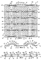
Figure 1 is an isometric view looking down upon a pallet not forming part of the invention; -
Figure 2 is a plan view looking down on the pallet shown inFigure 1 ; -
Figure 3 is an end view of the pallet shown inFigure 1 ; -
Figure 4 is a side view of the pallet shown inFigure 1 ; -
Figure 5 is another isometric view of portion of the pallet shown inFigure 1 ; -
Figure 6 is a perspective view of a stack of ten pallets, each pallet being as shown inFigure 1 ; -
Figure 7 is an end view of the stack shown inFigure 6 ; -
Figure 8 is a cutaway detail view of portion of the stack shown inFigure 6 ; -
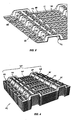
Figure 9 is an isometric view of a pallet according to an embodiment of the invention; -
Figure 10 is an enlarged isometric view of portion of the pallet shown inFigure 9 ; -
Figure 11 is a perspective view of a stack of ten pallets, each pallet being as shown inFigure 9 ; -
Figure 12 is an end view of the stack shown inFigure 11 ; and -
Figure 13 is a detail cutaway view of portion of the stack shown inFigure 11 . - The
pallet 10 shown inFigures 1 to 5 is injection moulded from a suitable engineering plastics material (such as HDPE) and has a generally thin wall construction. Thepallet 10 has a generally planarcentral panel 12, a pair of parallel inverted channels 14 and 16 extending across thepallet 10, and a pair ofedge panels 18 on the opposite side of each channel to where thecentral panel 12 is. - Each channel 14 and 16 forms an open-
bottomed tunnel Figures 3 and 4 ) shared by thecentral panel 12 and theedge panels 18. Each tunnel extends from oneend 20 of the pallet to theother end 22. Eachtunnel inboard side wall 24 and anoutboard side wall 26, and anupper wall 28 which extends between thetops - The
tunnels pallet 10 is approximately 1.1m square and the tunnels are spaced 640mm centre to centre. On its underside, each tunnel is approximately 200mm wide and 55mm deep. - The
inboard side wall 24 of each tunnel rises from a respectiveinboard edge 30 of thecentral panel 12. The other twoedges 32 of the central panel form portion ofrespective ends outboard side wall 26 of each tunnel rises from aninboard edge 34 of arespective edge panel 18. Opposite saidinboard edge 34, theoutboard edge 36 of theedge panel 18 forms afull side edge 38 of thepallet 10. - To assist rigidity of the pallet, six elongate
composite humps 37 extend across the pallet transverse to the longitudinal direction of thetunnels composite hump 37 extends across thecentral panel 12, theedge panels 18, theside walls upper walls 28 of the tunnels. Each hump is formed as an elongate bulge protruding from the surrounding surfaces of the pallet. - An
array 39 of six raised elongatecentral hump portions 40 is moulded into thecentral panel 12. Eachcentral hump portion 40 forms a central portion of a respectivecomposite hump 37. The term "composite hump" refers to a hump which comprises a linked series of hump portions which abut each other end to end. - The
central hump portions 40 in thearray 39 are parallel to each other and have the form of a raised ridge having a generally flatupper face 42 and near-vertical side walls 44. Eachcentral hump portion 40 extends laterally across thecentral panel 12 from oneinboard edge 30 of the central panel to the otherinboard edge 30 of the central panel. - Six raised elongate edge
panel hump portions 48 are moulded into eachedge panel 18 and are longitudinally aligned with thecentral hump portions 40 on the central panel. Each edgepanel hump portion 48 extends across itsrespective edge panel 18 from itsinboard edge 34 to itsoutboard edge 36. - The
hump portions central panel 12 andedge panels 18 respectively extend transverse to the longitudinal direction of thetunnels 15. Thehump portions underside 46 of the pallet. Thehump portions - The tunnel-
top hump portions 50, positioned on theupper wall 28 of the tunnels, are aligned vertically (but offset horizontally) with correspondingcentral hump portions 40 on the central panel, and corresponding edgepanel hump portions 48 on the edge panels. The tunnel-top hump portions 50 are narrower (about half the width) compared with thecentral hump portions 40 on the central panel and the edgepanel hump portions 48 on the edge panels. Each tunnel-top hump portion 50 is linked to aligned corresponding hump portions on the central panel and edge panels by means ofbuttresses 52 which extend up theside walls buttresses 52 are thin-walled and haveopen bottoms 54. - Each
composite hump 37 comprises onecentral hump portion 40 in the central panel, two edgepanel hump portions 48 on the edge panels, two tunnel-top hump portions 50 on the upper walls and four buttresses 52. The hump portions are linked or joined end to end in the relevant order. Each hump portion is connected directly to its adjoining hump portion or portions in a manner that smoothly continues or blends the walls of the hump portions. The hump portions can be considered to abut end to end although the exact position of that abutment may be unclear due to the smooth blending of the walls of the various features concerned. - The
central panel 12,edge panels 18 andupper walls 28 of tunnels are thus each divided into five flat horizontal surfaces separated byinboard humps 47.Edge humps 49 extend along respective edges at eachend - The edge buttresses 52a and tunnel-
top hump portions 50a of theedge humps 49 differ from the inboard buttresses 52b and tunnel-top hump portions 50b of theinboard humps 47. For theinboard humps 47, the top 55 of each inboard buttress 52b extends in an arch up to above the height of the upper face 51b of the associated inboard tunnel-top hump portion 50b. This provides additional strength to resist flattening of the tunnels when the pallet is loaded. For theedge humps 49 theupper face 51a of the edge tunnel-top hump portions 50a is raised higher than for inboard tunnel-top hump portions 50b to provide increased resistance to flattening of the tunnels at theends 22 when under load. Although the edge buttresses 52a of theedge humps 49 extend to the same height as thebuttresses 50b on theinboard humps 47, theedge hump portions 50a also extend to the height of the edge buttresses 52a, so there is no arching over at the top of the edge buttresses 52a. - The
open bottoms tunnels pallets 10 to nest into each other when stacked as shown inFigures 6 to 8 . Nested pallets are prevented from jamming together by the configuration of eight of thebuttresses 52. The eight buttresses in that selection are referred to herein as support buttresses 56. The support buttresses 56 are located next to the edge buttresses 52a and their configuration is different to the other buttresses. While thelower portion 58 of the upper faces 60 of most of the buttresses are curved to blend smoothly into the upper faces 42 and 45 of thehump portions lower portion 62 of the support buttresses 56 incorporate astep 64 having ahorizontal platform portion 66 which ends at anend wall portion 68 which drops to the associatedhump portion - The
step 64 is a relatively thin walled moulded hollow portion formed integrally with the remainder of the pallet. Within the hollow (ie on the underside of) eachstep 64 is arib 70 having the form of a vertically aligned planar web extending down from the under-surface of thestep 64, and extending fromside wall 57 toside wall 57 of the support buttress 56 and approximately centrally to thestep 64. Thebottom edge 71 of therib 70 is aligned with thelower surface 72 or 73 of the adjacent portion ofrespective panel Figure 8 , when such pallets are stacked upon each other, thebottom edge 71 of eachrib 70 bears against theupper surface 65 of astep 64 on the underlying pallet, so successivelyunderlying ribs 70 form a structural column wherein a load is transferred to thecorresponding rib 70 below. This means that whenpallets 10 are stacked in a nested configuration on each other on a floor and a load is placed on the upper pallet, the weight of that load is transmitted at least in part through to the floor by way of the column of vertically alignedribs 70. - The
horizontal portions central panel 12 andedge panels 18 respectively and theupper walls 28 of the tunnels are each formed as an open square lattice. Theholes 78 in thecentral panel 12 andupper walls 28 of the tunnels are 42.5mm square and theholes 78 in theedge panels 18 are 42.5 x 47.5mm. The lattice configuration provides a lighter pallet because it requires less material without an unacceptable reduction in strength, The strap portions of thecentral panel 12 andedge panels 18 are 2.5mm thick, while theside walls strap portions 80 on theupper walls 28, all have a 3.5mm thickness (ie 40% thicker material) for additional strength. Apallet 10 as described above weighs approximately 3.3kg. It is preferable for the wall thickness of the portions of the pallet to not differ by more than 50% of their smallest nominal thickness. - Each
pallet 10 is approximately 80mm high measured from thelower surfaces 72 and 73 to the upper faces 51. When nested in astack 69 of ten pallets as shown inFigure 7 , thestack 69 is approximately 260mm high overall. Each pallet added to the stack increases the height of the stack by only 20mm, which increase is 25% of the height of a freestandingindividual pallet 10. This particularly compact form of stacking is anadvantage pallet 10 over prior art pallets of equivalent load carrying capacity. - It will be appreciated that the
pallets 10 can be nested as described only if there is no base or lower wall in thetunnels - Any prior art pallet which may have had forklift tine accepting tunnels of this type, ie tunnels without a base, would have a tendency for the tunnels to flatten when an FIBC, typically weighing up to 1 tonne, is placed on it. However in the case of the embodiment described above the raised
hump portions buttresses 52 provide sufficient strength and resistance to bending that the tunnels can remain open for forklift access with loads on the pallets of up to 2 tonne. Thus FIBCs supported bypallets 10 may be stacked two-high and still allow for a forklift to lift both at once. If additional carrying capacity is required, two pallets may be nested together in order to provide increased stiffness. - The raised
hump portions arched tops 55 of the buttresses provide protrusions which assist to prevent slipping of an FIBC on thepallet 10. - The
pallet 110 shown inFigures 9 and 10 , and stacked inFigures 11 to 13 , has many features in common withpallet 10 although some of the features are modified. - The
pallet 110 has two pairs oftunnels 115 of the general type astunnels 15 described above. Each pair oftunnels 115 is aligned at right angles to the other pair. A forklift is thus able to lift thepallet 110 from any one of four directions. In contrast thepallet 10 described earlier can be lifted only from either of its two ends. - The
tunnels 115 separate the remaining surface of the pallet into nine main regions which are generally planar apart from humps bulging upwards therefrom. The nine regions are acentral panel 112, fouredge panels 118 and fourcorner panels 119. Thecentral panel 112 is bounded by all fourtunnels 115. Theedge panels 118 are bounded by three tunnels and arespective edge 121 of thepallet 110. The corner panels are bounded by two tunnels and twoedges 121 of the pallet. - The
pallet 110 has linked hump portions bulging upwards from the top surface of the pallet. Those hump portions are linked to form four elongate inboardcomposite humps 137 and onecomposite edge hump 149. - Each inboard
composite hump 137 extends from oneedge 121 of the pallet to anadjacent edge 121. Each inboardcomposite hump 137 extends over twotunnels 115, over thecentral panel 112 and across twoedge panels 118. Each inboardcomposite hump 137 bends through a 90° curve at itscentre 182 on thecentral panel 112. - The
edge hump 149 extends around the full perimeter of the pallet, passing over each end of each tunnel, along theoutboard edge 136 of eachedge panel 118 and along both outboard edges 135 of eachcorner panel 119. - Where each
inboard hump 137 passes over atunnel 115, one inboard buttress 152b links each tunnel-top hump portion 150b to a respective central hump portion 140 and another inboard buttress 152b links each tunnel-top hump portion 150b to the respective central hump portion 140. - The edge buttresses 152a and tunnel-top hump portions 150a of the
composite edge hump 149 differ from the inboard buttresses 152b and tunnel-top hump portions 150b of the central hump portions 140. For the central hump portions 140, the top 155 of each inboard buttress 152b extends in an arch up to above the height of theupper face 151b of the associated inboard tunnel-top hump portion 150b. For thecomposite edge humps 149 theupper face 151a of the edge tunnel-top hump portions 150a is raised higher than for inboard tunnel-top hump portions 150b to provide increased resistance to flattening of the tunnels at theedges 121 when under load. - A
curved bend portion 184 of thehump 137 provides the 90° curve at thecentre 182 of the inboardcomposite hump 137. - The
open bottoms tunnels 115 and buttresses 152 permit thepallets 110 to nest into each other when stacked as shown inFigures 11 to 13 . Nested pallets are prevented from jamming together by the configuration of eight of thebuttresses 152. The eight buttresses in that selection are referred to herein as support buttresses 156. - While the lower portion of the upper faces of most of the buttresses are curved to blend smoothly into the upper faces of the abutting hump portions, the lower portion of the support buttresses 156 incorporate a
step 164 having ahorizontal platform portion 166 which ends at an end wall portion 168 which drops to the associated hump portion. Thestep 164 has the same configuration and general function asstep 64 described above. - The
step 164 is a relatively thin walled moulded hollow portion formed integrally with the remainder of the pallet. Within the hollow (ie on the underside of) eachstep 164 is arib 170 having the form of a vertically aligned planar web extending down from the undersurface of thestep 164, and extending from side wall to side wall of the support buttress 156 and approximately centrally to thestep 164. Thebottom edge 171 of therib 170 is aligned with the lower surface of the adjacent portion of respective panels. As can be seen particularly in the cutaway portion ofFigure 13 , when such pallets are stacked upon each other, thebottom edge 171 of eachrib 170 bears against the upper surface of astep 164 on the underlying pallet, so successivelyunderlying ribs 170 form a structural column wherein a load is transferred to thecorresponding rib 170 below. This means that whenpallets 110 are stacked in a nested configuration on each other on a floor and a load is placed on the upper pallet, the weight of that load is transmitted at least in part through to the floor by way of the column of vertically alignedribs 170. - All the support buttresses 156 are buttresses which rise against the walls of one of the pairs of tunnels. The other pair of tunnels is not directly associated with any support buttresses. Four of the support buttresses 156a have their step positioned on a respective corner panel, whereas the other four support buttresses 156b have their step positioned on the
central panel 112. - The horizontal portions of the
central panel 112,edge panels 118 andcorner panels 119 respectively and the upper walls of the tunnels are each formed as an open square lattice in the manner described above forpallet 10 inFigure 1 . Apallet 110 as described weighs approximately 3.3kg when the wall thickness for all parts is nominally 2.5mm. The wall thickness is preferably in the range 2.0 to 3.0mm. - In a further embodiment (not illustrated) which is a modification of
pallet 110, eachcomposite hump 137 continues straight across thecentral panel 112 instead of turning through the 90° curve. - It will be also understood that where the word "comprise", and variations such as "comprises" and "comprising", are used in this specification, unless the context requires otherwise such use is intended to imply the inclusion of a stated feature or features but is not to be taken as excluding the presence of other feature or features.
- It will be also understood that where the term "inboard edge" is used in this specification, it is intended to refer to an edge of a feature which does not run along an outside edge (that is, on the perimeter) of the pallet. Similarly where the term "inboard end" is used in this specification, it is intended to refer to an end of a feature which is not at an outside edge (that is, not on the perimeter) of the pallet.
- It will be also understood that where the term "open" is used in this specification in relation to the "inverted open channel shape" of the tunnels adapted to accept the forklift tines, that term is intended to mean that no portion of the pallet extends across the longitudinal opening defined by that channel.
- The reference to any prior art in this specification is not, and should not be taken as, an acknowledgment or any form of suggestion that such prior art forms part of the common general knowledge.
Claims (13)
- A flexible intermediate bulk container pallet (110) moulded from plastics material comprising:- a generally planar central panel portion (112);- a first pair of parallel inverted open channels extending across the pallet in a first direction and rising upwards from the plane of said central panel portion to form a respective first pair of open-ended tunnels (115) having a longitudinal direction; characterised in that:- a second pair of parallel inverted open channels extend across the pallet in a second direction at right angles to said first direction and rise upwards from said plane of said central panel portion to form a respective second pair of open-ended tunnels (115) having a longitudinal direction;- each said tunnel extends fully between two respective opposite ends of the pallet; and- a first pair of edge panel portions (118), and a second pair of edge panel portions (118), all extend generally co-planar with said central panel;- each said tunnel (115) has:- a respective upper wall and two side walls- a first of its said side walls adjoining a corresponding inboard edge of said central panel;- the second of its said side walls adjoining an inboard edge of a corresponding said edge panel;- a first array of raised elongate first humps (150a, 150b) bulging upwards from its said upper wall of the tunnels, each said first hump extending laterally across a respective said upper wall,- a first end of each said first hump abutting a first end of a respective first buttress (152) which extends up said first side wall; and- a second end of each said first hump abutting a first end of a respective second buttress (152) which extends up said second side wall;- a second array of raised elongate second humps (140) bulge upwards from said central panel, each said second hump extending either from one said inboard edge of the central panel to an adjacent said inboard edge of the central panel or from one said inboard edge of the central panel straight across the central panel to another said inboard edge of the central panel, each end of each said second hump being linked to its respective said tunnel by a respective said first buttress; and- a third array of raised elongate third humps (148) bulge upwards from each said edge panel, each said third hump extending from a said inboard edge of a respective edge panel to a respective outer edge of the respective edge panel transverse to the longitudinal direction of its adjacent said tunnel, an inboard end of each said third hump being linked to its respective said tunnel by a respective said second buttress.
- A pallet according to claim 1 wherein a first selection of said buttresses rise above the height of their abutting said first humps.
- A pallet according to claim 2 wherein a second selection of said first humps and associated said first buttress and said second buttress are located at each end of each said tunnel, and said first humps in said second selection rise to substantially the same height as the buttresses in said second selection.
- A pallet according to any one of claims 1 to 3 wherein a fourth array of raised elongate fourth humps bulges upwards from the outer edge of each said edge panel, a fifth array of raised curved fifth humps bulges upwards from the upper wall of each of a respective corner panel bounded by two respective tunnels and two respective edges of the pallet, and said elongate humps with buttresses are connected such that each end of each said hump is linked to its respective said tunnel by a buttress which extends up the corresponding said side wall to a corresponding hump and provides a continuous perimeter hump around the perimeter of the pallet.
- A pallet according to claim 4 wherein said first buttresses are connected to the perimeter hump by means of the first humps on the panels.
- A pallet according to any one of claims 1 to 5 wherein said buttresses are hollow and fully open along their length to the underside of the pallet.
- A pallet according to any one of claims 1 to 6 wherein the nominal wall thicknesses of the plastics material in the central panel portion, the edge panel portions and the tunnels differ by no more than 50% of their smallest nominal thickness.
- A pallet according to claim 7 wherein all the nominal wall thicknesses of the plastics material in the central panel, the edge panels and the tunnels are substantially the same.
- A pallet according to any one of claims 1 to 8 said pallet being stackable in a nested stack of pallets identical thereto wherein the addition of each said pallet to the stack increases the height of the stack by no more than 30% of the height of a freestanding individual said pallet.
- A pallet according to claim 9 wherein the addition of each said pallet to the stack increases the height of the stack by about 25% of the height of a freestanding individual said pallet.
- A pallet according to any one of claims 1 to 10 wherein a plurality of said buttresses each incorporate a step comprising a substantially horizontal platform, each step providing an engagement means which extends to level with the lower surface of the adjacent portion of the respective central panel or edge panel whereby, when like said panels are stacked nested together, load from an upper said pallet may be transmitted through the engagement means of said upper pallet to the underlying platform of a said pallet nested immediately below said upper pallet.
- A pallet according to claim 11 wherein each said step is hollow except for a rib which extends across the buttress and from the underside of said platform to level with the lower surface of the adjacent portion of the respective central panel or edge panel whereby, when like said panels are nested together, load from an upper said pallet may be transmitted through the rib of the upper pallet to the underlying platform of said pallet nested immediately below said upper pallet.
- A method of transporting a flexible intermediate bulk container at least substantially filled with bulk material, said method comprising placing the container onto a pallet (110) according to any one of the preceding claims, engaging the tines of a forklift apparatus with a pair of said tunnels (115) and lifting the pallet and container by raising the forklift tines.
Priority Applications (1)
| Application Number | Priority Date | Filing Date | Title |
|---|---|---|---|
| PL11791756T PL2580136T3 (en) | 2010-06-11 | 2011-06-14 | Pallet for bulk bags |
Applications Claiming Priority (2)
| Application Number | Priority Date | Filing Date | Title |
|---|---|---|---|
| AU2010902576A AU2010902576A0 (en) | 2010-06-11 | Pallet for Bags | |
| PCT/AU2011/000720 WO2011153593A1 (en) | 2010-06-11 | 2011-06-14 | Pallet for bags |
Publications (3)
| Publication Number | Publication Date |
|---|---|
| EP2580136A1 EP2580136A1 (en) | 2013-04-17 |
| EP2580136A4 EP2580136A4 (en) | 2015-07-15 |
| EP2580136B1 true EP2580136B1 (en) | 2018-08-01 |
Family
ID=45097408
Family Applications (1)
| Application Number | Title | Priority Date | Filing Date |
|---|---|---|---|
| EP11791756.7A Active EP2580136B1 (en) | 2010-06-11 | 2011-06-14 | Pallet for bulk bags |
Country Status (12)
| Country | Link |
|---|---|
| US (2) | US20130136573A1 (en) |
| EP (1) | EP2580136B1 (en) |
| JP (1) | JP5998386B2 (en) |
| CN (1) | CN102834327B (en) |
| AU (1) | AU2011264426B2 (en) |
| CA (1) | CA2836163C (en) |
| DK (1) | DK2580136T3 (en) |
| ES (1) | ES2692661T3 (en) |
| NZ (1) | NZ601214A (en) |
| PL (1) | PL2580136T3 (en) |
| TR (1) | TR201815387T4 (en) |
| WO (1) | WO2011153593A1 (en) |
Families Citing this family (16)
| Publication number | Priority date | Publication date | Assignee | Title |
|---|---|---|---|---|
| US9873547B2 (en) | 2013-03-15 | 2018-01-23 | Tippmann Companies Llc | Heat transfer system for warehoused goods |
| US9027487B1 (en) | 2014-03-18 | 2015-05-12 | Intrek Logistics Llc | Pallet with lateral tine openings |
| US8776697B1 (en) * | 2014-03-18 | 2014-07-15 | Intrek Logistics Llc | Pallet with tine support elements |
| PL2930121T3 (en) | 2014-04-11 | 2016-12-30 | Plastic pallet for receiving flexible bulk containers | |
| USD735962S1 (en) * | 2014-04-26 | 2015-08-04 | PMK Rescue Solutions | Modular load carrying system |
| JP5721091B1 (en) * | 2014-08-03 | 2015-05-20 | 保雄 渡部 | Pallet and prefabricated container |
| ES2783823T3 (en) * | 2017-05-02 | 2020-09-18 | Cabka Group Gmbh | Plastic loading platform with reinforcement structure |
| US10414542B2 (en) | 2017-08-29 | 2019-09-17 | Walmart Apollo, Llc | Concave-pallet design with a lip |
| US10239658B1 (en) * | 2017-10-31 | 2019-03-26 | Advancepierre Foods, Inc. | Pallet spacer |
| TWI648203B (en) * | 2018-04-18 | 2019-01-21 | 新台塑膠工業股份有限公司 | Grooved pallet structure |
| KR102053131B1 (en) * | 2018-07-11 | 2019-12-06 | 엔피씨(주) | Pallet for bulk bag |
| US11708192B2 (en) * | 2019-01-05 | 2023-07-25 | Ponera Group Sagl | Assortment of pallet modules, and pallet assembly built of the same |
| CN113227601B (en) * | 2019-02-15 | 2023-02-28 | Nok株式会社 | Cushion rubber, method for adjusting reaction force thereof, and base |
| US20200307857A1 (en) | 2019-03-25 | 2020-10-01 | Pallets.Com Llc | All-in-one plastic pallet |
| ES2930117T3 (en) * | 2019-11-07 | 2022-12-07 | Wimao Oy | pallet |
| US11661237B1 (en) * | 2020-07-24 | 2023-05-30 | Formall, Inc. | Pallet assembly |
Family Cites Families (27)
| Publication number | Priority date | Publication date | Assignee | Title |
|---|---|---|---|---|
| US2455197A (en) * | 1946-05-09 | 1948-11-30 | Gen Motors Corp | Material supporting pallet |
| US2544743A (en) * | 1946-10-08 | 1951-03-13 | Vrabcak Richard | Pallet |
| US2615661A (en) * | 1947-08-28 | 1952-10-28 | Walton W Cushman | Metal pallet |
| US3135228A (en) * | 1961-01-27 | 1964-06-02 | Woodkor Corp | Pallet construction |
| US3112715A (en) * | 1961-06-09 | 1963-12-03 | Monsanto Chemicals | Foldable expendable pallet |
| US3167341A (en) * | 1961-08-16 | 1965-01-26 | William J Higgins | Nestable shipping pallets |
| US3120825A (en) * | 1962-05-28 | 1964-02-11 | Associated Box Corp | Platform |
| US3187688A (en) * | 1963-12-30 | 1965-06-08 | Woodkor Corp | Pallet |
| US3272158A (en) * | 1964-06-16 | 1966-09-13 | Leslie F Barnum | Molded pallet |
| US3759194A (en) * | 1970-12-19 | 1973-09-18 | Dainippon Ink & Chemicals | Plastic pallet |
| US3702100A (en) * | 1971-04-05 | 1972-11-07 | Menasha Corp | Molded pallet |
| GB1347948A (en) * | 1972-02-29 | 1974-02-27 | Kupersmit J B | Moulded pallet and shipping containers |
| DE7245517U (en) * | 1972-12-13 | 1973-03-15 | Bischof Und Klein | palette |
| JPS5152464U (en) * | 1974-10-17 | 1976-04-21 | ||
| US4145974A (en) * | 1978-01-31 | 1979-03-27 | P. C. B. Inc. | Pallet |
| JPS57140325U (en) * | 1981-02-26 | 1982-09-02 | ||
| FR2500811A1 (en) * | 1981-02-27 | 1982-09-03 | Guilpain Jean Paul | NEW TRANSPORT AND HANDLING PALLET |
| EP0125307B1 (en) * | 1982-11-17 | 1990-05-02 | Weyerhaeuser Company | Container |
| JPS6190724U (en) * | 1984-11-15 | 1986-06-12 | ||
| JPS63199935U (en) * | 1987-06-10 | 1988-12-22 | ||
| AU1314301A (en) * | 1999-11-12 | 2001-06-06 | Chequer Corporation Limited | Pallet for support and transport of large bag-like containers |
| US6928933B2 (en) * | 2001-07-13 | 2005-08-16 | William G. Grau | Printing press racking board and corner angle support |
| US7607628B2 (en) * | 2002-04-03 | 2009-10-27 | Stratis Corporation | Pallet |
| CN1319814C (en) * | 2002-09-06 | 2007-06-06 | 有限会社圣特鲁思 | Method and apparatus for producing pallet |
| CN2601951Y (en) * | 2002-12-04 | 2004-02-04 | 倪美琴 | Bed plate of integrated-shaped plastic container |
| USD533328S1 (en) * | 2004-04-28 | 2006-12-05 | Akinobu Wake | Corrugated plate for pallet |
| JP5156261B2 (en) * | 2007-04-27 | 2013-03-06 | キョーラク株式会社 | palette |
-
2010
- 2010-06-14 US US13/635,850 patent/US20130136573A1/en not_active Abandoned
-
2011
- 2011-06-14 ES ES11791756.7T patent/ES2692661T3/en active Active
- 2011-06-14 WO PCT/AU2011/000720 patent/WO2011153593A1/en active Application Filing
- 2011-06-14 JP JP2013513498A patent/JP5998386B2/en active Active
- 2011-06-14 AU AU2011264426A patent/AU2011264426B2/en active Active
- 2011-06-14 CA CA2836163A patent/CA2836163C/en active Active
- 2011-06-14 TR TR2018/15387T patent/TR201815387T4/en unknown
- 2011-06-14 PL PL11791756T patent/PL2580136T3/en unknown
- 2011-06-14 NZ NZ601214A patent/NZ601214A/en unknown
- 2011-06-14 DK DK11791756.7T patent/DK2580136T3/en active
- 2011-06-14 EP EP11791756.7A patent/EP2580136B1/en active Active
- 2011-06-14 CN CN201180018450.8A patent/CN102834327B/en active Active
-
2014
- 2014-07-22 US US14/337,995 patent/US10583959B2/en active Active
Non-Patent Citations (1)
| Title |
|---|
| None * |
Also Published As
| Publication number | Publication date |
|---|---|
| EP2580136A4 (en) | 2015-07-15 |
| CA2836163C (en) | 2018-06-19 |
| WO2011153593A1 (en) | 2011-12-15 |
| AU2011264426A1 (en) | 2012-08-02 |
| PL2580136T3 (en) | 2019-01-31 |
| TR201815387T4 (en) | 2018-11-21 |
| ES2692661T3 (en) | 2018-12-04 |
| AU2011264426B2 (en) | 2018-01-18 |
| CN102834327B (en) | 2016-03-23 |
| US20140331902A1 (en) | 2014-11-13 |
| JP2013531586A (en) | 2013-08-08 |
| CN102834327A (en) | 2012-12-19 |
| CA2836163A1 (en) | 2011-12-15 |
| US10583959B2 (en) | 2020-03-10 |
| US20130136573A1 (en) | 2013-05-30 |
| JP5998386B2 (en) | 2016-09-28 |
| EP2580136A1 (en) | 2013-04-17 |
| DK2580136T3 (en) | 2018-11-26 |
| NZ601214A (en) | 2015-05-29 |
Similar Documents
| Publication | Publication Date | Title |
|---|---|---|
| EP2580136B1 (en) | Pallet for bulk bags | |
| US8857634B2 (en) | Transport pallet | |
| AU699906B2 (en) | Twin-sheet thermoformed pallet with high stiffness deck | |
| CA2557952C (en) | Interlocking roll support and spacing structure | |
| US20090050030A1 (en) | Nestable pallet | |
| US20080308015A1 (en) | Nestable Pallet | |
| US20080296194A1 (en) | Nestable and stackable container for the transport of heavy baked items | |
| GB2216101A (en) | Crates for transporting rubber blocks or sheets | |
| US5941177A (en) | Recyclable, heavy duty, lightweight, moisture resistant corrugated fiberboard pallet | |
| JP7357937B2 (en) | Shipping pallets and/or decks useful for shipping | |
| US20100326334A1 (en) | Reinforced plastic pallet | |
| MX2007000691A (en) | Container. | |
| ES2538855T3 (en) | Transport plate for items in bags | |
| EP3456645B1 (en) | Plastic container for storing and transporting agricultural products and method for stacking containers | |
| US5649640A (en) | Pallet-type storage/transport container | |
| US20120285851A1 (en) | Modular top frame | |
| JPH0226824Y2 (en) | ||
| AU774721B2 (en) | Stackable folding container | |
| AU776023B2 (en) | A pallet | |
| WO2000041941A1 (en) | A pallet which is nestable when stacked | |
| US20070277474A1 (en) | Polymeric batten for load strapping and spacing | |
| JPH04173545A (en) | Crate for transportation of rubber block or sheet | |
| JPH0948523A (en) | Sheet-material mounting pallet |
Legal Events
| Date | Code | Title | Description |
|---|---|---|---|
| PUAI | Public reference made under article 153(3) epc to a published international application that has entered the european phase |
Free format text: ORIGINAL CODE: 0009012 |
|
| 17P | Request for examination filed |
Effective date: 20120903 |
|
| AK | Designated contracting states |
Kind code of ref document: A1 Designated state(s): AL AT BE BG CH CY CZ DE DK EE ES FI FR GB GR HR HU IE IS IT LI LT LU LV MC MK MT NL NO PL PT RO RS SE SI SK SM TR |
|
| DAX | Request for extension of the european patent (deleted) | ||
| RA4 | Supplementary search report drawn up and despatched (corrected) |
Effective date: 20150616 |
|
| RIC1 | Information provided on ipc code assigned before grant |
Ipc: B65D 19/24 20060101AFI20150610BHEP |
|
| 17Q | First examination report despatched |
Effective date: 20161006 |
|
| STAA | Information on the status of an ep patent application or granted ep patent |
Free format text: STATUS: EXAMINATION IS IN PROGRESS |
|
| GRAP | Despatch of communication of intention to grant a patent |
Free format text: ORIGINAL CODE: EPIDOSNIGR1 |
|
| STAA | Information on the status of an ep patent application or granted ep patent |
Free format text: STATUS: GRANT OF PATENT IS INTENDED |
|
| INTG | Intention to grant announced |
Effective date: 20180108 |
|
| RIN1 | Information on inventor provided before grant (corrected) |
Inventor name: SHAW, IAN ANDREW Inventor name: WADDELL, COLIN Inventor name: BERRY, ANDREW |
|
| GRAS | Grant fee paid |
Free format text: ORIGINAL CODE: EPIDOSNIGR3 |
|
| GRAA | (expected) grant |
Free format text: ORIGINAL CODE: 0009210 |
|
| STAA | Information on the status of an ep patent application or granted ep patent |
Free format text: STATUS: THE PATENT HAS BEEN GRANTED |
|
| AK | Designated contracting states |
Kind code of ref document: B1 Designated state(s): AL AT BE BG CH CY CZ DE DK EE ES FI FR GB GR HR HU IE IS IT LI LT LU LV MC MK MT NL NO PL PT RO RS SE SI SK SM TR |
|
| REG | Reference to a national code |
Ref country code: GB Ref legal event code: FG4D |
|
| REG | Reference to a national code |
Ref country code: CH Ref legal event code: EP Ref country code: AT Ref legal event code: REF Ref document number: 1024006 Country of ref document: AT Kind code of ref document: T Effective date: 20180815 |
|
| REG | Reference to a national code |
Ref country code: IE Ref legal event code: FG4D |
|
| REG | Reference to a national code |
Ref country code: DE Ref legal event code: R096 Ref document number: 602011050612 Country of ref document: DE |
|
| REG | Reference to a national code |
Ref country code: NL Ref legal event code: FP |
|
| REG | Reference to a national code |
Ref country code: DK Ref legal event code: T3 Effective date: 20181119 |
|
| REG | Reference to a national code |
Ref country code: ES Ref legal event code: FG2A Ref document number: 2692661 Country of ref document: ES Kind code of ref document: T3 Effective date: 20181204 |
|
| REG | Reference to a national code |
Ref country code: LT Ref legal event code: MG4D |
|
| REG | Reference to a national code |
Ref country code: AT Ref legal event code: MK05 Ref document number: 1024006 Country of ref document: AT Kind code of ref document: T Effective date: 20180801 |
|
| PG25 | Lapsed in a contracting state [announced via postgrant information from national office to epo] |
Ref country code: IS Free format text: LAPSE BECAUSE OF FAILURE TO SUBMIT A TRANSLATION OF THE DESCRIPTION OR TO PAY THE FEE WITHIN THE PRESCRIBED TIME-LIMIT Effective date: 20181201 Ref country code: AT Free format text: LAPSE BECAUSE OF FAILURE TO SUBMIT A TRANSLATION OF THE DESCRIPTION OR TO PAY THE FEE WITHIN THE PRESCRIBED TIME-LIMIT Effective date: 20180801 Ref country code: SE Free format text: LAPSE BECAUSE OF FAILURE TO SUBMIT A TRANSLATION OF THE DESCRIPTION OR TO PAY THE FEE WITHIN THE PRESCRIBED TIME-LIMIT Effective date: 20180801 Ref country code: NO Free format text: LAPSE BECAUSE OF FAILURE TO SUBMIT A TRANSLATION OF THE DESCRIPTION OR TO PAY THE FEE WITHIN THE PRESCRIBED TIME-LIMIT Effective date: 20181101 Ref country code: RS Free format text: LAPSE BECAUSE OF FAILURE TO SUBMIT A TRANSLATION OF THE DESCRIPTION OR TO PAY THE FEE WITHIN THE PRESCRIBED TIME-LIMIT Effective date: 20180801 Ref country code: FI Free format text: LAPSE BECAUSE OF FAILURE TO SUBMIT A TRANSLATION OF THE DESCRIPTION OR TO PAY THE FEE WITHIN THE PRESCRIBED TIME-LIMIT Effective date: 20180801 Ref country code: GR Free format text: LAPSE BECAUSE OF FAILURE TO SUBMIT A TRANSLATION OF THE DESCRIPTION OR TO PAY THE FEE WITHIN THE PRESCRIBED TIME-LIMIT Effective date: 20181102 Ref country code: BG Free format text: LAPSE BECAUSE OF FAILURE TO SUBMIT A TRANSLATION OF THE DESCRIPTION OR TO PAY THE FEE WITHIN THE PRESCRIBED TIME-LIMIT Effective date: 20181101 Ref country code: LT Free format text: LAPSE BECAUSE OF FAILURE TO SUBMIT A TRANSLATION OF THE DESCRIPTION OR TO PAY THE FEE WITHIN THE PRESCRIBED TIME-LIMIT Effective date: 20180801 |
|
| PG25 | Lapsed in a contracting state [announced via postgrant information from national office to epo] |
Ref country code: HR Free format text: LAPSE BECAUSE OF FAILURE TO SUBMIT A TRANSLATION OF THE DESCRIPTION OR TO PAY THE FEE WITHIN THE PRESCRIBED TIME-LIMIT Effective date: 20180801 Ref country code: AL Free format text: LAPSE BECAUSE OF FAILURE TO SUBMIT A TRANSLATION OF THE DESCRIPTION OR TO PAY THE FEE WITHIN THE PRESCRIBED TIME-LIMIT Effective date: 20180801 Ref country code: LV Free format text: LAPSE BECAUSE OF FAILURE TO SUBMIT A TRANSLATION OF THE DESCRIPTION OR TO PAY THE FEE WITHIN THE PRESCRIBED TIME-LIMIT Effective date: 20180801 |
|
| PG25 | Lapsed in a contracting state [announced via postgrant information from national office to epo] |
Ref country code: RO Free format text: LAPSE BECAUSE OF FAILURE TO SUBMIT A TRANSLATION OF THE DESCRIPTION OR TO PAY THE FEE WITHIN THE PRESCRIBED TIME-LIMIT Effective date: 20180801 Ref country code: EE Free format text: LAPSE BECAUSE OF FAILURE TO SUBMIT A TRANSLATION OF THE DESCRIPTION OR TO PAY THE FEE WITHIN THE PRESCRIBED TIME-LIMIT Effective date: 20180801 Ref country code: IT Free format text: LAPSE BECAUSE OF FAILURE TO SUBMIT A TRANSLATION OF THE DESCRIPTION OR TO PAY THE FEE WITHIN THE PRESCRIBED TIME-LIMIT Effective date: 20180801 |
|
| REG | Reference to a national code |
Ref country code: DE Ref legal event code: R097 Ref document number: 602011050612 Country of ref document: DE |
|
| PG25 | Lapsed in a contracting state [announced via postgrant information from national office to epo] |
Ref country code: SM Free format text: LAPSE BECAUSE OF FAILURE TO SUBMIT A TRANSLATION OF THE DESCRIPTION OR TO PAY THE FEE WITHIN THE PRESCRIBED TIME-LIMIT Effective date: 20180801 Ref country code: SK Free format text: LAPSE BECAUSE OF FAILURE TO SUBMIT A TRANSLATION OF THE DESCRIPTION OR TO PAY THE FEE WITHIN THE PRESCRIBED TIME-LIMIT Effective date: 20180801 |
|
| PLBE | No opposition filed within time limit |
Free format text: ORIGINAL CODE: 0009261 |
|
| STAA | Information on the status of an ep patent application or granted ep patent |
Free format text: STATUS: NO OPPOSITION FILED WITHIN TIME LIMIT |
|
| 26N | No opposition filed |
Effective date: 20190503 |
|
| PG25 | Lapsed in a contracting state [announced via postgrant information from national office to epo] |
Ref country code: SI Free format text: LAPSE BECAUSE OF FAILURE TO SUBMIT A TRANSLATION OF THE DESCRIPTION OR TO PAY THE FEE WITHIN THE PRESCRIBED TIME-LIMIT Effective date: 20180801 |
|
| PG25 | Lapsed in a contracting state [announced via postgrant information from national office to epo] |
Ref country code: MC Free format text: LAPSE BECAUSE OF FAILURE TO SUBMIT A TRANSLATION OF THE DESCRIPTION OR TO PAY THE FEE WITHIN THE PRESCRIBED TIME-LIMIT Effective date: 20180801 |
|
| REG | Reference to a national code |
Ref country code: CH Ref legal event code: PL |
|
| PG25 | Lapsed in a contracting state [announced via postgrant information from national office to epo] |
Ref country code: CH Free format text: LAPSE BECAUSE OF NON-PAYMENT OF DUE FEES Effective date: 20190630 Ref country code: LI Free format text: LAPSE BECAUSE OF NON-PAYMENT OF DUE FEES Effective date: 20190630 Ref country code: LU Free format text: LAPSE BECAUSE OF NON-PAYMENT OF DUE FEES Effective date: 20190614 |
|
| PG25 | Lapsed in a contracting state [announced via postgrant information from national office to epo] |
Ref country code: PT Free format text: LAPSE BECAUSE OF FAILURE TO SUBMIT A TRANSLATION OF THE DESCRIPTION OR TO PAY THE FEE WITHIN THE PRESCRIBED TIME-LIMIT Effective date: 20181201 |
|
| PG25 | Lapsed in a contracting state [announced via postgrant information from national office to epo] |
Ref country code: CY Free format text: LAPSE BECAUSE OF FAILURE TO SUBMIT A TRANSLATION OF THE DESCRIPTION OR TO PAY THE FEE WITHIN THE PRESCRIBED TIME-LIMIT Effective date: 20180801 |
|
| PG25 | Lapsed in a contracting state [announced via postgrant information from national office to epo] |
Ref country code: MT Free format text: LAPSE BECAUSE OF FAILURE TO SUBMIT A TRANSLATION OF THE DESCRIPTION OR TO PAY THE FEE WITHIN THE PRESCRIBED TIME-LIMIT Effective date: 20180801 |
|
| PG25 | Lapsed in a contracting state [announced via postgrant information from national office to epo] |
Ref country code: MK Free format text: LAPSE BECAUSE OF FAILURE TO SUBMIT A TRANSLATION OF THE DESCRIPTION OR TO PAY THE FEE WITHIN THE PRESCRIBED TIME-LIMIT Effective date: 20180801 |
|
| P01 | Opt-out of the competence of the unified patent court (upc) registered |
Effective date: 20230525 |
|
| PGFP | Annual fee paid to national office [announced via postgrant information from national office to epo] |
Ref country code: NL Payment date: 20230620 Year of fee payment: 13 Ref country code: IE Payment date: 20230620 Year of fee payment: 13 Ref country code: FR Payment date: 20230627 Year of fee payment: 13 Ref country code: DK Payment date: 20230622 Year of fee payment: 13 Ref country code: DE Payment date: 20230620 Year of fee payment: 13 Ref country code: CZ Payment date: 20230606 Year of fee payment: 13 |
|
| PGFP | Annual fee paid to national office [announced via postgrant information from national office to epo] |
Ref country code: TR Payment date: 20230613 Year of fee payment: 13 Ref country code: PL Payment date: 20230602 Year of fee payment: 13 Ref country code: HU Payment date: 20230622 Year of fee payment: 13 |
|
| PGFP | Annual fee paid to national office [announced via postgrant information from national office to epo] |
Ref country code: BE Payment date: 20230620 Year of fee payment: 13 |
|
| PGFP | Annual fee paid to national office [announced via postgrant information from national office to epo] |
Ref country code: GB Payment date: 20230622 Year of fee payment: 13 Ref country code: ES Payment date: 20230829 Year of fee payment: 13 |