EP2580109B1 - A vehicle having a swivel wheel - Google Patents
A vehicle having a swivel wheel Download PDFInfo
- Publication number
- EP2580109B1 EP2580109B1 EP12738206.7A EP12738206A EP2580109B1 EP 2580109 B1 EP2580109 B1 EP 2580109B1 EP 12738206 A EP12738206 A EP 12738206A EP 2580109 B1 EP2580109 B1 EP 2580109B1
- Authority
- EP
- European Patent Office
- Prior art keywords
- stem
- tricycle
- front wheel
- fork
- handle
- Prior art date
- Legal status (The legal status is an assumption and is not a legal conclusion. Google has not performed a legal analysis and makes no representation as to the accuracy of the status listed.)
- Active
Links
Images


Classifications
-
- B—PERFORMING OPERATIONS; TRANSPORTING
- B62—LAND VEHICLES FOR TRAVELLING OTHERWISE THAN ON RAILS
- B62B—HAND-PROPELLED VEHICLES, e.g. HAND CARTS OR PERAMBULATORS; SLEDGES
- B62B1/00—Hand carts having only one axis carrying one or more transport wheels; Equipment therefor
- B62B1/10—Hand carts having only one axis carrying one or more transport wheels; Equipment therefor in which the load is intended to be transferred totally to the wheels
- B62B1/12—Hand carts having only one axis carrying one or more transport wheels; Equipment therefor in which the load is intended to be transferred totally to the wheels involving parts being adjustable, collapsible, attachable, detachable, or convertible
-
- B—PERFORMING OPERATIONS; TRANSPORTING
- B21—MECHANICAL METAL-WORKING WITHOUT ESSENTIALLY REMOVING MATERIAL; PUNCHING METAL
- B21K—MAKING FORGED OR PRESSED METAL PRODUCTS, e.g. HORSE-SHOES, RIVETS, BOLTS OR WHEELS
- B21K21/00—Making hollow articles not covered by a single preceding sub-group
-
- B—PERFORMING OPERATIONS; TRANSPORTING
- B21—MECHANICAL METAL-WORKING WITHOUT ESSENTIALLY REMOVING MATERIAL; PUNCHING METAL
- B21K—MAKING FORGED OR PRESSED METAL PRODUCTS, e.g. HORSE-SHOES, RIVETS, BOLTS OR WHEELS
- B21K21/00—Making hollow articles not covered by a single preceding sub-group
- B21K21/02—Producing blanks in the shape of discs or cups as semifinished articles for making hollow articles, e.g. to be deep-drawn or extruded
-
- B—PERFORMING OPERATIONS; TRANSPORTING
- B62—LAND VEHICLES FOR TRAVELLING OTHERWISE THAN ON RAILS
- B62B—HAND-PROPELLED VEHICLES, e.g. HAND CARTS OR PERAMBULATORS; SLEDGES
- B62B5/00—Accessories or details specially adapted for hand carts
- B62B5/06—Hand moving equipment, e.g. handle bars
- B62B5/067—Stowable or retractable handle bars
-
- B—PERFORMING OPERATIONS; TRANSPORTING
- B62—LAND VEHICLES FOR TRAVELLING OTHERWISE THAN ON RAILS
- B62B—HAND-PROPELLED VEHICLES, e.g. HAND CARTS OR PERAMBULATORS; SLEDGES
- B62B7/00—Carriages for children; Perambulators, e.g. dolls' perambulators
- B62B7/04—Carriages for children; Perambulators, e.g. dolls' perambulators having more than one wheel axis; Steering devices therefor
- B62B7/12—Carriages for children; Perambulators, e.g. dolls' perambulators having more than one wheel axis; Steering devices therefor convertible, e.g. into children's furniture or toy
-
- B—PERFORMING OPERATIONS; TRANSPORTING
- B62—LAND VEHICLES FOR TRAVELLING OTHERWISE THAN ON RAILS
- B62B—HAND-PROPELLED VEHICLES, e.g. HAND CARTS OR PERAMBULATORS; SLEDGES
- B62B9/00—Accessories or details specially adapted for children's carriages or perambulators
- B62B9/20—Handle bars; Handles
-
- B—PERFORMING OPERATIONS; TRANSPORTING
- B62—LAND VEHICLES FOR TRAVELLING OTHERWISE THAN ON RAILS
- B62D—MOTOR VEHICLES; TRAILERS
- B62D1/00—Steering controls, i.e. means for initiating a change of direction of the vehicle
- B62D1/02—Steering controls, i.e. means for initiating a change of direction of the vehicle vehicle-mounted
- B62D1/12—Hand levers
-
- B—PERFORMING OPERATIONS; TRANSPORTING
- B62—LAND VEHICLES FOR TRAVELLING OTHERWISE THAN ON RAILS
- B62H—CYCLE STANDS; SUPPORTS OR HOLDERS FOR PARKING OR STORING CYCLES; APPLIANCES PREVENTING OR INDICATING UNAUTHORIZED USE OR THEFT OF CYCLES; LOCKS INTEGRAL WITH CYCLES; DEVICES FOR LEARNING TO RIDE CYCLES
- B62H7/00—Devices for learning to ride cycles, not otherwise provided for, e.g. assisting balance
-
- B—PERFORMING OPERATIONS; TRANSPORTING
- B62—LAND VEHICLES FOR TRAVELLING OTHERWISE THAN ON RAILS
- B62J—CYCLE SADDLES OR SEATS; AUXILIARY DEVICES OR ACCESSORIES SPECIALLY ADAPTED TO CYCLES AND NOT OTHERWISE PROVIDED FOR, e.g. ARTICLE CARRIERS OR CYCLE PROTECTORS
- B62J1/00—Saddles or other seats for cycles; Arrangement thereof; Component parts
-
- B—PERFORMING OPERATIONS; TRANSPORTING
- B62—LAND VEHICLES FOR TRAVELLING OTHERWISE THAN ON RAILS
- B62J—CYCLE SADDLES OR SEATS; AUXILIARY DEVICES OR ACCESSORIES SPECIALLY ADAPTED TO CYCLES AND NOT OTHERWISE PROVIDED FOR, e.g. ARTICLE CARRIERS OR CYCLE PROTECTORS
- B62J15/00—Mud-guards for wheels
-
- B—PERFORMING OPERATIONS; TRANSPORTING
- B62—LAND VEHICLES FOR TRAVELLING OTHERWISE THAN ON RAILS
- B62K—CYCLES; CYCLE FRAMES; CYCLE STEERING DEVICES; RIDER-OPERATED TERMINAL CONTROLS SPECIALLY ADAPTED FOR CYCLES; CYCLE AXLE SUSPENSIONS; CYCLE SIDE-CARS, FORECARS, OR THE LIKE
- B62K13/00—Cycles convertible to, or transformable into, other types of cycles or land vehicle
- B62K13/08—Frames
-
- B—PERFORMING OPERATIONS; TRANSPORTING
- B62—LAND VEHICLES FOR TRAVELLING OTHERWISE THAN ON RAILS
- B62K—CYCLES; CYCLE FRAMES; CYCLE STEERING DEVICES; RIDER-OPERATED TERMINAL CONTROLS SPECIALLY ADAPTED FOR CYCLES; CYCLE AXLE SUSPENSIONS; CYCLE SIDE-CARS, FORECARS, OR THE LIKE
- B62K21/00—Steering devices
- B62K21/02—Front wheel forks or equivalent, e.g. single tine
-
- B—PERFORMING OPERATIONS; TRANSPORTING
- B62—LAND VEHICLES FOR TRAVELLING OTHERWISE THAN ON RAILS
- B62K—CYCLES; CYCLE FRAMES; CYCLE STEERING DEVICES; RIDER-OPERATED TERMINAL CONTROLS SPECIALLY ADAPTED FOR CYCLES; CYCLE AXLE SUSPENSIONS; CYCLE SIDE-CARS, FORECARS, OR THE LIKE
- B62K21/00—Steering devices
- B62K21/08—Steering dampers
-
- B—PERFORMING OPERATIONS; TRANSPORTING
- B62—LAND VEHICLES FOR TRAVELLING OTHERWISE THAN ON RAILS
- B62K—CYCLES; CYCLE FRAMES; CYCLE STEERING DEVICES; RIDER-OPERATED TERMINAL CONTROLS SPECIALLY ADAPTED FOR CYCLES; CYCLE AXLE SUSPENSIONS; CYCLE SIDE-CARS, FORECARS, OR THE LIKE
- B62K21/00—Steering devices
- B62K21/18—Connections between forks and handlebars or handlebar stems
- B62K21/24—Connections between forks and handlebars or handlebar stems readily releasable
-
- B—PERFORMING OPERATIONS; TRANSPORTING
- B62—LAND VEHICLES FOR TRAVELLING OTHERWISE THAN ON RAILS
- B62K—CYCLES; CYCLE FRAMES; CYCLE STEERING DEVICES; RIDER-OPERATED TERMINAL CONTROLS SPECIALLY ADAPTED FOR CYCLES; CYCLE AXLE SUSPENSIONS; CYCLE SIDE-CARS, FORECARS, OR THE LIKE
- B62K27/00—Sidecars; Forecars; Trailers or the like specially adapted to be attached to cycles
- B62K27/003—Trailers
-
- B—PERFORMING OPERATIONS; TRANSPORTING
- B62—LAND VEHICLES FOR TRAVELLING OTHERWISE THAN ON RAILS
- B62K—CYCLES; CYCLE FRAMES; CYCLE STEERING DEVICES; RIDER-OPERATED TERMINAL CONTROLS SPECIALLY ADAPTED FOR CYCLES; CYCLE AXLE SUSPENSIONS; CYCLE SIDE-CARS, FORECARS, OR THE LIKE
- B62K5/00—Cycles with handlebars, equipped with three or more main road wheels
- B62K5/02—Tricycles
- B62K5/06—Frames for tricycles
-
- B—PERFORMING OPERATIONS; TRANSPORTING
- B62—LAND VEHICLES FOR TRAVELLING OTHERWISE THAN ON RAILS
- B62K—CYCLES; CYCLE FRAMES; CYCLE STEERING DEVICES; RIDER-OPERATED TERMINAL CONTROLS SPECIALLY ADAPTED FOR CYCLES; CYCLE AXLE SUSPENSIONS; CYCLE SIDE-CARS, FORECARS, OR THE LIKE
- B62K9/00—Children's cycles
- B62K9/02—Tricycles
-
- B—PERFORMING OPERATIONS; TRANSPORTING
- B62—LAND VEHICLES FOR TRAVELLING OTHERWISE THAN ON RAILS
- B62M—RIDER PROPULSION OF WHEELED VEHICLES OR SLEDGES; POWERED PROPULSION OF SLEDGES OR SINGLE-TRACK CYCLES; TRANSMISSIONS SPECIALLY ADAPTED FOR SUCH VEHICLES
- B62M1/00—Rider propulsion of wheeled vehicles
- B62M1/36—Rider propulsion of wheeled vehicles with rotary cranks, e.g. with pedal cranks
- B62M1/38—Rider propulsion of wheeled vehicles with rotary cranks, e.g. with pedal cranks for directly driving the wheel axle
-
- B—PERFORMING OPERATIONS; TRANSPORTING
- B62—LAND VEHICLES FOR TRAVELLING OTHERWISE THAN ON RAILS
- B62M—RIDER PROPULSION OF WHEELED VEHICLES OR SLEDGES; POWERED PROPULSION OF SLEDGES OR SINGLE-TRACK CYCLES; TRANSMISSIONS SPECIALLY ADAPTED FOR SUCH VEHICLES
- B62M6/00—Rider propulsion of wheeled vehicles with additional source of power, e.g. combustion engine or electric motor
-
- H—ELECTRICITY
- H05—ELECTRIC TECHNIQUES NOT OTHERWISE PROVIDED FOR
- H05K—PRINTED CIRCUITS; CASINGS OR CONSTRUCTIONAL DETAILS OF ELECTRIC APPARATUS; MANUFACTURE OF ASSEMBLAGES OF ELECTRICAL COMPONENTS
- H05K999/00—PRINTED CIRCUITS; CASINGS OR CONSTRUCTIONAL DETAILS OF ELECTRIC APPARATUS; MANUFACTURE OF ASSEMBLAGES OF ELECTRICAL COMPONENTS dummy group
- H05K999/99—PRINTED CIRCUITS; CASINGS OR CONSTRUCTIONAL DETAILS OF ELECTRIC APPARATUS; MANUFACTURE OF ASSEMBLAGES OF ELECTRICAL COMPONENTS dummy group dummy group
-
- B—PERFORMING OPERATIONS; TRANSPORTING
- B62—LAND VEHICLES FOR TRAVELLING OTHERWISE THAN ON RAILS
- B62B—HAND-PROPELLED VEHICLES, e.g. HAND CARTS OR PERAMBULATORS; SLEDGES
- B62B2202/00—Indexing codes relating to type or characteristics of transported articles
- B62B2202/26—Handbags, e.g. shopping bags
-
- B—PERFORMING OPERATIONS; TRANSPORTING
- B62—LAND VEHICLES FOR TRAVELLING OTHERWISE THAN ON RAILS
- B62B—HAND-PROPELLED VEHICLES, e.g. HAND CARTS OR PERAMBULATORS; SLEDGES
- B62B2206/00—Adjustable or convertible hand-propelled vehicles or sledges
- B62B2206/006—Convertible hand-propelled vehicles or sledges
-
- B—PERFORMING OPERATIONS; TRANSPORTING
- B62—LAND VEHICLES FOR TRAVELLING OTHERWISE THAN ON RAILS
- B62B—HAND-PROPELLED VEHICLES, e.g. HAND CARTS OR PERAMBULATORS; SLEDGES
- B62B5/00—Accessories or details specially adapted for hand carts
- B62B5/0026—Propulsion aids
- B62B5/0079—Towing by connecting to another vehicle
-
- B—PERFORMING OPERATIONS; TRANSPORTING
- B62—LAND VEHICLES FOR TRAVELLING OTHERWISE THAN ON RAILS
- B62B—HAND-PROPELLED VEHICLES, e.g. HAND CARTS OR PERAMBULATORS; SLEDGES
- B62B7/00—Carriages for children; Perambulators, e.g. dolls' perambulators
- B62B7/04—Carriages for children; Perambulators, e.g. dolls' perambulators having more than one wheel axis; Steering devices therefor
- B62B7/12—Carriages for children; Perambulators, e.g. dolls' perambulators having more than one wheel axis; Steering devices therefor convertible, e.g. into children's furniture or toy
- B62B7/126—Carriages for children; Perambulators, e.g. dolls' perambulators having more than one wheel axis; Steering devices therefor convertible, e.g. into children's furniture or toy into a trailer, e.g. bicycle trailer
Definitions
- the invention generally relates to the field of riding vehicles.
- tricycles may be used for riders of different sizes and capabilities. Some tricycles are configured to be propelled and steered by the rider. In some instances, tricycles are configured to be pushed from behind, by an individual, such as an adult pushing a child. Typically, when the tricycle is propelled by the rider, the rider uses the pedals attached to the front wheel and steers the tricycle using a handle which is typically connected to the front wheel. Tricycles configured to be pushed from behind sometimes include a mechanical steering mechanism to permit an adult walking behind the tricycle to mechanically turn the front wheel. For example, FR2955080 describes a tricycle with a steering handle arranged at a rear part of the frame, and a transmission system transmitting rotation of the steering handle to a front fork supporting a front wheel.
- An exemplary embodiment of the invention includes a tricycle operable between a first mode of operation steerable by a tricycle rider, and a second mode of operation steerable by an individual pushing the tricycle.
- first and second modes an orientation of the front wheel remains unchanged regardless of mode of operation. That is, the wheel axis need not necessarily be locked in a position leading the fork axis when the tricycle is in the first mode.
- a tricycle includes a fork having at least one blade configured to support a front wheel in a manner permitting the front wheel to rotate about a front wheel axis.
- a stem extends from the fork, and a handle is configured to turn the fork around a stem axis transverse to the front wheel axis.
- the handle in the first mode, is rotationally coupled with the stem in a manner permitting a tricycle rider to exert forces on the handle and thereby turn the fork.
- the handle is rotationally uncoupled from the stem, preventing forces on the handle from turning the fork.
- a rotation restrictor prevents the front wheel from turning to a position where the wheel axis leads the fork axis, and for maintaining the wheel axis in a position trailing the fork axis both when the handle is in the first mode and when the handle is in the second mode.
- the rotation restrictor is configured to permit the front wheel to turn less than 180 degrees (and in another exemplary embodiment less than 100 degrees), while maintaining the front wheel in a position such that the wheel axis trails the fork axis.
- Embodiments of the invention include a tricycle operable between a first mode of operation steerable by a tricycle rider, and a second mode of operation steerable by an individual pushing the tricycle.
- a tricycle as used herein, includes any vehicle with a wheel in the front and two wheels in the rear.
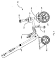
- Fig. 1 illustrates is a side view of a tricycle, and which can be used in a first mode of operation where a rider may propel the tricycle using pedals 141 and 142 (see Fig. 3 ).
- a second mode of operation may be accomplished when an individual behind the tricycle, pushes the tricycle using, for example, parental handle 500, as illustrated in Fig. 2 .
- Embodiments of the invention include a tricycle having a frame and a pair of rear wheels for rotatable connection to the frame.
- exemplary tricycle 800 may include a main frame 700 including head tube 707.
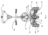
- Two rear wheels 400 (see Fig. 3 ) may be supported toward the rear of the main frame 700.
- the main frame 700 may be made of any material or have any structure, shape, or configuration capable of supporting a tricycle rider.
- main frame 700 may include metal tubing or any other rigid material, and may be configured to support a seat 600.
- the rear wheels 400 may be rotatably supported on a central axle (the support shaft 702 of which is illustrated in Fig. 3 ) which may be inserted into the rear part of the main frame 700, effectively allowing the rear wheels 400 to rotate frontwards or backwards.
- a seat 600 may be connected, by any known method, to the main frame 700.
- the seat may have any configuration capable of supporting a rider. It may include or omit a back rest, may be integrally formed or formed of multiple materials, and/or may be uncovered or covered in cloth, fabric, or other material.
- the main frame 700 may also have a number of connection options for seat 600, effectively allowing the placing/adjustment of seat 600 at a number of locations along the main frame 700.
- a basket 410 may be added and placed on the rear part of main frame 700 between the rear wheels 400.
- Fig. 2 is similar to Fig. 1 , adding a parental handle, which may be permanent, semi-permanent (e.g., removable with tools), or designed to be removable at will.
- parental handle 500 illustrated in Fig. 2 may be made of one or more metal pipes or from any other rigid material.
- the parental handle 500 may be telescopically adjustable to accommodate the height of the individual pushing the tricycle 810.
- the adjustable height mechanism of parental handle 500 may belong to any of the known adjusting techniques such as by a popup pin held within the inner pipe of the handle and which pops out of one of the holes of the outer pipe, where the pin may be pushed from one hole and popped out of a different hole, for adjusting the height of the handle.
- Embodiments of the invention also include a front wheel having opposing sides and a front wheel axis.
- front wheel 100 includes first side 102 and opposing second side 104.
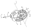
- the wheel 100 as illustrated in Fig. 4b , includes a central axis c at its midpoint 303, about which the wheel 100 is rotatable.
- embodiments of the invention may include a pair of pedals, each pedal configured to rotate the front wheel.
- pedals may include fixed pedals, removable pedals, foldable pedals, or pedals that flip up, retract, or have an otherwise alterable configuration.
- pedal refers to any structure that permits a rider to propel a tricycle using foot power.
- An example of pedals, consistent with embodiments of the invention, include pedals 141 and 142 (see, e.g., Fig 3 ).
- a pedal may be configured to rotate the front wheel a portion of the time (e.g., during the first mode when the rider propels the tricycle, and may be removable from, disengagable from, folded onto, or otherwise deactivatable during a second portion of the time (e.g., during the second mode when a parent pushes the tricycle from behind).
- Each of pedals 141 and 142 may be connected to the center of the front wheel 100, via pedal rod 140.
- the pedal rod may be continuous and connected to both pedals, or the pedal rod 140 may be configured of two independent sections, each connected to a separate one of the pedals 141 and 142.
- the propelling factor of pedal rod 140 may be connected, by any mechanical interconnection means, to a rotating factor of the front wheel 100, thereby allowing rotation of the front wheel 100 using pedal rod 140.
- the front wheel 100 may be rotated about its center axis, i.e. about the middle part of pedal rod 140 which may act as the front wheel 100 axle.
- the wheel may have a separate axle to which one or a pair of pedal rods connect.
- Pedal rod 140 may include three parts; a middle part located at a center of the wheel 100 and used, among others, as an axle of wheel 100, a left side for connection to a left pedal, and a right side for connection to a right pedal 141.
- Embodiments of the invention include at least one blade configured to support the front wheel in a manner permitting the front wheel to rotate about the front wheel axis.
- blade includes any structure capable of supporting the front wheel in a rotatable manner.
- a wheel may be supported, for example, on a single blade or on a pair of blades.
- Fig. 1 illustrates an example of a blade 130 used to rotatably support wheel 100.
- Fig. 3 illustrates wheel 100 supported by a pair of blades 130 and 131.
- a fork When a pair of blades are employed, they are typically interconnected at upper ends opposite points at which they interconnect to the wheel axis and are collectively referred to as a fork (although, as used herein, the term fork may also include structures that have just one blade.) Thus, in various figures, a fork is generally designated with the reference numeral 130.
- the fork may be formed of individual blades that curve toward each other, or, interconnecting structure may join two individual fork blades.
- the middle part of pedal rod 140 may be pivotally held by the opposing distal ends of fork blades 130 and 131 in a manner such that the front wheel is capable of rotating about its center axis.
- a mud guard 301 may be disposed near a top of the fork 133, opposite distal ends supporting the wheel.
- Embodiments of the invention also include a stem extending from the fork and being rotatably connectable to the frame.
- a stem may be any structure connected to the fork and that is capable of conveying a turning force to the fork and/or that supports the fork in a rotatable manner.
- Fig. 4a illustrates stem 305 that extends from fork 133.
- the stem may be rotatably connected to the frame 700 via the frame's head tube 707.
- the frame's head tube 707 may be a part of the frame 700, wielded to frame 700, or connected to frame 700 by any other means such as screws.
- the width of the front wheel may be at least three times greater than the minimum diameter of the fork's stem. This configuration can lower turning friction, facilitating control from behind during the second mode of operation.
- the stem may include a steel tube that has a minimum diameter that is at least four times smaller than a width of the front wheel.
- the stem may be comprised of sections having varying diameters. In the above examples, a smallest or "minimum" diameter may be of particular interest, especially if that minimum diameter is at a rotational stem connection.
- the stem when the front wheel is in a range of 25 to 51 mm, the stem may have a minimum diameter of 6 to 11 mm. For example, when the front wheel is in a range of 45 to 55 mm, the stem may have a minimum diameter of 9 to 11 mm. For example, when the front wheel is in a range of 20 to 60 mm, the stem may have a minimum diameter of 4 to 15 mm.
- the stem's minimum diameter may be greater than one third the width of the front wheel, and the invention, in its broadest sense is not limited to any particular dimension.
- the stem may be held by a bearing which may reduce turning friction and facilitate the second mode operation and the first mode of operation as well.
- stem 305 may have a central axis a
- fork 133 may have a fork axis b and the stem 305 may be connected to the fork 133 in a manner such that the central axes a and b form an obtuse angle x therebetween.
- Angle x may be, for example, equal to or less than about 179° degrees. In some embodiments, angle x may be between about 170°-174°. In another embodiment the angle x may be between about 165°-179°. In a further embodiment the angle x may be between about 165°-173°. In yet another embodiment, the angle x may be between about 170°-175°.
- a minimum stem diameter of three to four times smaller than the width of the front wheel may be desirable.
- width w of front wheel 100 may be at least three to four times greater than minimum diameter d of stem 305.
- the stem may have a minimum diameter d of 6 to 12 mm.
- the stem when the front wheel width w is in a range of 45 to 55 mm, the stem may have a minimum diameter d of 9 to 11 mm. For example, when the front wheel width w is in a range of 20 to 60 mm, the stem may have a minimum diameter d of 4 to 15 mm.
- the central axis a of stem 305 extends transverse to and is offset from rotational axis c of front wheel 100 by a distance y .
- the minimal distance y may be no more than about 50mm.
- the offset distance y is in the range of between about 18mm and 25mm.
- offset distance y is in a range of about 15mm and 40mm. As the offset distance decreases with all else equal, so to decreases an ability to turn the tricycle from behind using parental handle 500.
- the angle x between the stem and the fork is between about 7 and 10 degrees
- the minimum diameter d of the stem 305 is at least three times less than the width w of the front wheel.
- the fork axis a is designed to lead the front wheel axis c regardless of whether the tricycle is in the first mode of rider steering control or the second mode of parental steering control.
- the leading stem axis in such instances positions the pedals further rearward than they would ordinarily be if the stem axis a trailed the wheel axis c , potentially giving rise to a concern that the pedals may be too close to the rider for comfort.
- the frame 700 may be configured to maintain a fixed, non-adjustable distance between the fork stem and the rear wheels. This can occur, for example by constructing the frame 700 from a fixed length, non-adjustable piece of material.
- the shortest distance between the front wheel center and the imaginary line of the fork axis is between 10mm-30mm. In one embodiment, the shortest distance between the front wheel center and the imaginary line of the fork axis is between 15mm-25mm. In another embodiment the front wheel axis is designed to trail the stem axis in both mode of operations the first and the second. The figure though is non-limiting and alternatives may exist.
- the width of the front wheel is at least three times greater than the minimum diameter of the fork's stem.
- Embodiments of the invention may further include a rider handle, configured to turn the fork about a stem axis transverse to the front wheel axis.
- rider handle is used broadly to refer to any structure, regardless of shape, material, or size, that can be grasped by a tricycle rider and used to turn the front wheel.
- the rider handle may be in the form of a handlebar, with a curved rod-like shape, or a straight rod-like shape.
- the rider handle may be in the form of a steering wheel or other closed or opened loop structure capable of manipulation by a rider.
- the rider handle may have a solid or open core.
- the rider handle may be made of any material or combination of materials.
- the rider handle may be configured to turn the fork via a mechanical interconnection with, for example, either the fork or the stem.
- the mechanical interconnection may be direct or may include intermediate parts through which forces may be transferred via the rider handle to the front wheel.
- a rider handle may include handlebar assembly 200 illustrated in Figs. 1 and 2 .
- rider handle assembly 200 may include a handlebar 115, an arm 201, and a coupling mechanism 202.
- the rider handle in a first mode, is configured to be rotationally coupled with the stem in a manner permitting a tricycle rider to exert forces on the rider handle and thereby turn the fork, and the rider handle in the second mode, is configured to be rotationally uncoupled from the stem, preventing forces on the rider handle from turning the fork.
- Rotational coupling and decoupling of the rider handle from the fork may be accomplished in numerous mechanical ways, and the invention, in its broadest sense, is not limited to any particular mechanical interconnection. Rather, any manner in which the rider handle may be coupled and uncoupled to the fork is considered to fall within the scope and spirit of the invention.
- the location of a coupling decoupling mechanism is not necessarily critical to embodiments of the invention. It may be located between a rider handle assembly and a stem, or it may be located between a stem and a fork.
- the coupling mechanism 202 may, in a first mode, permit mechanical interconnection between the rider handle and the fork such that when a tricycle rider applies a turning force to the rider handle, the turning force is conveyed to the front wheel via the fork.
- the coupling mechanism 202 may decouple the rider handle from the fork in a manner permitting the rider handle to turn freely without conveying turning forces to the fork. This may be accomplished, for example, by permitting selective coupling and decoupling of the rider handle from the stem. (e.g., selective coupling and decoupling of rider handle assembly 200 and stem 305).
- Couple means herein to include any mechanical engagement which transfers the rotation of one part to the other coupled part, by causing it to rotate similarly.
- the steering of tricycle 800 is accomplished using rider handle assembly 200, i.e. the turning, e.g. left or right, of rider handle assembly 200 turns the fork 130 which turns the front wheel 100, the rider may assume control of steering while simultaneously propelling the tricycle 800 using the pedals 141 and 142. If when the rider is in control in the first mode, a person walking behind the tricycle tries to push the tricycle from behind using parental handle 500, the rider may prevent the person walking behind from assuming control. Thus the rider handle may be mechanically disconnected from the stem.
- the rider handle may cease to function as a steering mechanism and may simply function as support that the rider may grasp for balance or in order to permit a child to pretend to steer.
- the rider handle may lock in a stationary position rotationally disconnected from the fork and front wheel, or may rotate freely within a range of motion independent of the fork and the front wheel.
- a handle assembly may be rotatably coupled and decoupled from a fork or fork stem.
- the examples provided in this specification are not intended to limit the invention to any particular example.
- Other coupling and decoupling mechanisms may be used such as a detent, a pin, a screw connector, or any other connectors.
- a coupling member 204 associated with the rider handle assembly 200 may include a surface that selectively mates with an extension of the stem.
- a shaped end 308 of stem 305 is selectively mateable with a corresponding shaped slot 307 of coupling member 204.
- the stem's top end 308 in this example has an almost rectangular shape, although for most of its length the fork stem 305 is round.
- the opening 307 depicted in silhouette since the opening 307 is hidden from this view point, has a corresponding shape thereto.
- the fork stem 305 is affixed, i.e. it cannot rotate, inside the second coupling member 204.
- the almost rectangular shape is non-limiting and many other, non-round shapes can be used for the purpose of affixing the fork stem 305 inside the second coupling member's opening 307.
- a knob 810 or any other manually activatable release mechanism, which may be a part of the coupling mechanism 202, may be used for coupling the handle arm 201 to the fork's stem 305.
- knob 810 when knob 810 is lifted, decoupling occurs, and when it is moved downward onto stem 305, coupling occurs.
- rider handle assembly 200 is rotationally engageable with the fork's stem 305 in a manner permitting a tricycle rider to exert forces on the rider handle 200 and thereby turn the fork.
- the rider handle 200 in the second mode may be rotationally disengageable from the fork's stem 305 for preventing forces on the handle from turning the fork.
- Examples of other structures that may be used to selectively couple a handle to a stem include protruding spring-biased pins that can be depressed to decouple and which can snap back into place to couple; or using the pin 309 without part 810 for coupling and decoupling the ride handle 200 to the stem 305, as described in relations to fig. 7 , etc....
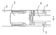
- Figure 5b is a cross-sectional view of a part of the coupling mechanism 202, according to one embodiment of the invention.
- the mechanism 202 allows coupling of the handle arm 201 and the fork stem 305.
- Three main members are depicted in the diagram: a first coupling member 203, a second coupling member 204 and a grasping member 810 (or a knob).
- the first coupling member 203 is statically coupled to the handle arm 201, thereinside. In the middle of the first coupling member 203 there is a shaft through which the fork stem 305 can be inserted.
- the second coupling member 204 is positioned inside the top end of the first coupling member 203, being slideable up and down.
- the fork stem 305 In the bottom of the second coupling member 204 there is an opening 307 into which the top end 308 of the fork stem 305 may fit.
- the second coupling member 204 When the second coupling member 204 is in its upper position, it is disengaged from the fork stem 305.
- the fork stem 305 When the second coupling member 204 slides down, the fork stem 305 is inserted into the opening 307, and a coupling is achieved between the second coupling member 204 and the fork stem 305, and hence also between the steering arm 201 and the fork stem 305.
- the fork stem 305 In order to affix the fork stem 305 inside the second coupling member's 204 opening, the fork stem 305 has a non-round shape in its top end and the opening has a corresponding shape thereto, as illustrated in a non-limiting way.
- the grasping member 810 is, on one hand, external to the handle arm's tube 201 and on the other hand internal and connected to the second coupling member 204, by a connecting element 309 such as a pin, a screw, or any other element.
- a connecting element 309 such as a pin, a screw, or any other element.
- the grasping member 810 as depicted in the diagram provides the individual using it a better grip and easier control on the second coupling member's 204 position (whether up or down).
- the grasping member 810 is redundant or not required, and then, the connecting element 309 alone may be used as a third coupling member, as described in relations to fig. 7 .
- the connecting element 309 has been depicted as a single element, such as pin etc. connecting both sides of the third coupling grasping member 810 via the handle arm 201 and the second coupling member 204.
- This is not mandatory though and in other embodiments other solutions can be applied instead.
- a third coupling member composed of two parts (e.g., a "right part” and a "left part")
- a short pin can be coupled to each part, while the short pin can penetrate the steering arm and form the connection with the second coupling member, whereas, in another embodiment, the two parts may be connected by a spring.
- second coupling member 204 may be designed from two interconnecting parts each made from a different material.
- the coupling mechanism 202 may be in the front tube 707 of the frame 700. In other embodiments, the coupling mechanism may appear on top of the front tube 707.
- FIG. 6 is a cross-sectional view of the handle arm 201 holding the first coupling member 203, according to one embodiment of the invention.
- the first coupling member 203 is held by grasping elements 610, such as snaps, in the handle arm's tube 201.
- grasping elements 610 such as snaps
- the shaft 306 is the shaft in which the fork stem may slide in.
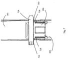
- Figure 7 is a cross-sectional side view of the second coupling member 204 inside the first coupling member 203, according to one embodiment of the invention.
- the handle arm's tube 201 there are grooves 713.
- a guiding element 714 connected to the second coupling member 204, can slide up and down, thus lifting and lowering, respectively, the second coupling member 204.
- the second coupling member 204 should stay in a low, down position when coupled to the pivot, and in an upper, high position when disconnected therefrom, a locking mechanism is described.
- this locking mechanism comprises protrusions 716 in the groove 713. When the guiding element crosses a protrusion 716, it is locked therebehind.
- the protrusion should be made of a flexible or resilient material.
- the steering arm is made of a non-flexible material, it is possible to attach thereto another layer of a flexible material, either from the inside or from the outside, forming the protrusion in this flexible layer.
- the first coupling member 203 which is attached to the handle tube 201 from the inside, can form this layer.
- grooves are seen also in the first coupling member 203, wherein the protrusions 716 are implemented therein.
- first coupling member as the flexible layer
- other solutions may be provided as a dedicated piece of flexible material which is attached to the handle arm's tube instead.
- Yet other embodiments may use other solutions, alternative to the protrusions, such as using a screw as the guiding element, screwing it in the position where it needs to be locked.
- the guiding element may form also the connecting element 309.
- the connecting element 309 which is additional to the guiding element.
- the guiding member alone may be the knob used for coupling and/or decoupling.
- Figure 8 illustrates the knob 810, according to one embodiment of the invention.
- the connecting element 309 is able to slide up and down in the groove.
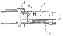
- Figure 9a is a cross-sectional side view of the coupling mechanism in the uncoupled position. It can be seen, from looking at figure 9a that the top end of the fork stem 305 is free, that is, it is not inserted into the opening 307 of the second coupling member 204.
- Figure 9b is a cross-sectional side view of the coupling mechanism in the coupled position. In figure 9b , illustrating the coupled position, the top end of the pivot is inserted into the opening 307.
- the fork stem 305 is rotatably held in the first coupling member 203. In order to keep the fork stem 305 held in the first coupling member 203, the fork stem 305 has an indentation 910.
- the indentation may include, for example, a groove that fully or partially circumscribes the stem 305, or it may include a confined recess in the stem 305.
- a locking member 911 having a spring 912, clenching the pivot's indentation, may prevent it from sliding out and releasing therefrom. Therefore, the locking member 911 may prevent the fork stem 305 from releasing from the coupling mechanism.
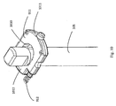
- FIG 10 is a perspective view of the holding mechanism for engaging the fork stem 305, according to one embodiment of the invention.
- the locking member 911 in this case, has an oval opening 1010 through which the head of fork stem 305 can pass, and one or more springs 912.
- the locking member 911 has a first side 1011 and a second side 1012. It is noted though that the locking member is not necessarily rectangular and it may not have definable sides. However, in order to explain the affixing mechanism, the embodiment illustrated is nearly rectangular in shape.
- the spring/springs 912 push the locking member 911 towards its 1011 side, against the tube's wall.
- the fork stem 305 Upon inserting the pivot into the shaft of the first coupling member, the fork stem 305 reaches the locking member 911. Then, the top of the pivot's end pushes the locking mechanism 911 towards its 1012 side. When the pivot's indentation reaches the locking mechanism 911, the spring/springs 912 are slightly released and push the mechanism into the indentation, thus affixing the fork stem 305 in correspondence to the locking mechanism 911 and hence also in correspondence with the first coupling member.
- the mechanism illustrated in figure 10 is non-limiting and many other one-time locking mechanisms known per se may be used alternatively, as applicable.
- Embodiments of the invention also include at least rotation restrictor, for preventing the front wheel from turning to a position where the front wheel axis leads the fork axis, and for maintaining the front wheel axis in a position trailing the fork axis both when the tricycle is propelled by a tricycle rider in the first mode and when the tricycle is pushed from behind in the second mode.
- a rotation restrictor for preventing includes any structure capable of restricting the rotational movement of the front wheel, regardless of whether the restrictor completely prevents rotation past a certain point, or whether the restrictor only prevents rotation past a certain point when forces exerted are below a threshold (e.g., the restrictor may exert a bias force that may be overcome by an opposing force greater than the bias force.)
- a rotation restrictor consistent with embodiments of the invention may be used to maintain the front wheel in an orientation where the front wheel axis trails the fork axis in both a first rider steering mode and a second parental control mode.
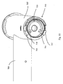
- FIG. 11 is a diagram of the frontal part of the main frame 700 and the head tube 707, from a bottom view, without the front wheel assembly and without the rider handle assembly 200, according to an embodiment of the invention.
- the head tube 707 described in relations to Figs. 1 and 2 , may include a rotation restrictor in the form of stop 710, for preventing the front wheel from turning to a position where the wheel axis leads the fork axis.
- a rotation restrictor in the form of stop 710, for preventing the front wheel from turning to a position where the wheel axis leads the fork axis.
- the stop 710 may have a number of protrusions, such as the protrusion 711, protrusion 712, protrusion 713, and protrusion 714. In one embodiment only two protrusions are needed, such as protrusions 711 and 713. In another embodiment only one protrusion may be needed. These protrusions may be used for limiting the swivel angle of the front wheel.
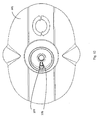
- Fig. 12 is a schematic diagram of the mud guard 301, according to an embodiment of the invention.
- the mud guard 301 as described in relations to Fig. 1 , may have at least one protrusion, two protrusions such as protrusions 377 and 378, or any number of protrusion.
- the protrusion 377 of mud guard 301 is meant to fit between the protrusions 712 and 713 of stop 710, whereas protrusion 378 of mud guard 301 is meant to fit between the protrusions 711 and 714.
- the limit of the protrusions of the mud guard 301 between the protrusions of the stop 710 allows on one hand the turning of the mud guard in a preset angle, hence the turning of the front wheel in a preset angel, and on the other hand prevents the mud guard from turning in a wider angle thus maintaining the wheel axis in a position trailing the fork axis both when the handle is in the first mode and when the handle is in the second mode.
- the turning angle between the protrusions of the stop 710 may be between 80° and 100°. In another embodiment, the turning angle between the protrusions of the stop 710 may be around 90°. In one embodiment the turning angle between the protrusions of the stop 710 may be less than 180°.
- a protrusion 723 may be added in order to prevent the assembling of the mud guard incorrectly.
- the stop may be designed differently and located in other parts of the tricycle as long as it prevents the front wheel from turning to a position where the wheel axis leads the fork axis.
- the stop may be located in the stem of the fork, in the mud guard, in the handle arm, or in any place externally or internally to the tricycle.
- one or more stops may be located on the fork and/or the stem, to restrict relative motion therebetween.
- one or more stops could be located on the stem and/or the handle to restrict relative motion therebetween.
- one or more stops might be located on a fixed portion of the tricycle, such as the frame or a fixed component connected to the frame, to restrict motion of any one of the fork, the stem, the handle, or a component connected to any one of the foregoing.
- a fixed portion of the tricycle such as the frame or a fixed component connected to the frame, to restrict motion of any one of the fork, the stem, the handle, or a component connected to any one of the foregoing.
- the rider handle angle is restricted as well due to safety considerations, protecting the body of the rider from being hit by the rider handle.
- the turning angle of the rider handle may be between 80° and 100°. In one embodiment the turning angle of the rider handle may be around 90°. In one embodiment the turning angle of the rider handle may be between 20° and 170°.
- the front wheel of a tricycle is always maintained in a position with the stem axis leading the wheel axis, regardless of whether the tricycle is propelled by a rider or pushed from behind.
- all a parent need do to take over steering control is to disengage the rider handle from the front wheel.
- the front wheel in this example, need not be rotated to a new position, since the wheel position may remain the same regardless of the mode of operation.
- all the parent need to do in this embodiment, is to couple the rider handle to the front wheel. Since rider steering control may be achieved with the stem axis leading the wheel axis, the parent need not re-orient the front wheel.
- the tricycle may provide an option of changing pedal position between modes of operation.
- a footrest 300 (see fig. 2 ) may be connected to the main frame 700 for allowing the rider to rest his feet on the footrest 300 while the tricycle 810 is being pushed from behind.
- the footrest 300 is foldable, and it may be folded backwards under the chair 600 or it may be folded in any other way.
- the pedal rod 140 propelling factor may be disengaged from the rotating factor of the wheel 102, effectively allowing the pedals to stay static while the tricycle 810 is being pushed.
- the method for engaging and disengaging the pedal rod propelling factor and the rotating factor of the wheel is known in the art.
- the rider handle 200 may be uncoupled from the fork 130, effectively allowing an individual to push the tricycle 810 from behind and steer it using the parental handle 500 while the rider sits on the chair 600, rests his feet on the foot rest 300 and rests his hands on the rider handle 200. Meaning that in this second mode of operation, the steering of the tricycle 810 does not have to interfere with the rider's hands holding the rider handle 200. Nevertheless, the tricycle 810 may be changed to the first mode of operation by coupling the fork 130 with the rider handle 200, optionally detaching the parental handle 500, optionally folding the footrest 300, and optionally reengaging the pedal rod 140 to the front wheel 102. Thus in the first mode of operation the rider can propel the tricycle 810 by himself using the pedal rod 140 and steer the tricycle 810 by himself using rider handle 200.
Description
- The invention generally relates to the field of riding vehicles.
- Whether used for transportation or recreation, tricycles may be used for riders of different sizes and capabilities. Some tricycles are configured to be propelled and steered by the rider. In some instances, tricycles are configured to be pushed from behind, by an individual, such as an adult pushing a child. Typically, when the tricycle is propelled by the rider, the rider uses the pedals attached to the front wheel and steers the tricycle using a handle which is typically connected to the front wheel. Tricycles configured to be pushed from behind sometimes include a mechanical steering mechanism to permit an adult walking behind the tricycle to mechanically turn the front wheel. For example,
FR2955080 - An exemplary embodiment of the invention includes a tricycle operable between a first mode of operation steerable by a tricycle rider, and a second mode of operation steerable by an individual pushing the tricycle. In both such first and second modes, an orientation of the front wheel remains unchanged regardless of mode of operation. That is, the wheel axis need not necessarily be locked in a position leading the fork axis when the tricycle is in the first mode.
- More specifically, a tricycle includes a fork having at least one blade configured to support a front wheel in a manner permitting the front wheel to rotate about a front wheel axis. A stem extends from the fork, and a handle is configured to turn the fork around a stem axis transverse to the front wheel axis. The handle, in the first mode, is rotationally coupled with the stem in a manner permitting a tricycle rider to exert forces on the handle and thereby turn the fork. In a second mode, the handle is rotationally uncoupled from the stem, preventing forces on the handle from turning the fork. A rotation restrictor prevents the front wheel from turning to a position where the wheel axis leads the fork axis, and for maintaining the wheel axis in a position trailing the fork axis both when the handle is in the first mode and when the handle is in the second mode.
- In one exemplary embodiment, the rotation restrictor is configured to permit the front wheel to turn less than 180 degrees (and in another exemplary embodiment less than 100 degrees), while maintaining the front wheel in a position such that the wheel axis trails the fork axis.
- In the drawings:
-
Fig. 1 is a side view of a tricycle, without parental handle, and which may be used in a first mode of operation, according to an embodiment of the invention. -
Fig. 2 is a side view of a tricycle, having a parental handle, which may be used in a second mode of operation, according to an embodiment of the invention. -
Figure 3 is front view of the tricycle ofFig. 2 . -
Fig. 4a is a side view of a front wheel fork and stem assembly consistent with an embodiment of the invention. -
Figure 4b is a perspective view of the front wheel assembly ofFig. 4a with mud guard added. -
Figure 5a is a front view of a handle assembly consistent with an embodiment of the invention. -
Figure 5b is a cross-sectional front view of a coupling assembly consistent with an embodiment of the invention. -
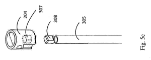
Figure 5c is a perspective assembly view of a stem and coupling member consistent with an embodiment of the invention. -
Fig 6 is a cross sectional side view of a coupling member consistent with an embodiment of the invention. -
Figure 7 is a cross-sectional side view of a coupling assembly consistent with an embodiment of the invention. -
Figure 8 is a cross-sectional side view of another coupling assembly consistent with an embodiment of the invention. -
Figure 9a is a cross-sectional side view of yet another coupling assembly in an uncoupled position, consistent with an embodiment of the invention. -
Figure 9b is a cross-sectional side view of the coupling assembly ofFig. 9a in a coupled position; -
Figure 10 is a perspective view of a holding mechanism, according to one embodiment of the invention. -
Fig. 11 is a perspective bottom view of the frame head tube consistent with an embodiment of the invention. -
Fig. 12 is a top view of a mud guard, consistent with an embodiment of the invention. - The terms of "front", "rear", "down", "up", "bottom", "upper", "horizontal", "vertical", "right", "left" or any reference to sides or directions are used throughout the description for the sake of brevity alone and are relative terms only and not intended to require a particular component orientation.
- Embodiments of the invention include a tricycle operable between a first mode of operation steerable by a tricycle rider, and a second mode of operation steerable by an individual pushing the tricycle. A tricycle, as used herein, includes any vehicle with a wheel in the front and two wheels in the rear.
Fig. 1 , for example, illustrates is a side view of a tricycle, and which can be used in a first mode of operation where a rider may propel thetricycle using pedals 141 and 142 (seeFig. 3 ). A second mode of operation may be accomplished when an individual behind the tricycle, pushes the tricycle using, for example,parental handle 500, as illustrated inFig. 2 . - Embodiments of the invention include a tricycle having a frame and a pair of rear wheels for rotatable connection to the frame. As illustrated in
Fig. 1 ,exemplary tricycle 800 may include amain frame 700 includinghead tube 707. Two rear wheels 400 (seeFig. 3 ) may be supported toward the rear of themain frame 700. Themain frame 700 may be made of any material or have any structure, shape, or configuration capable of supporting a tricycle rider. For example,main frame 700 may include metal tubing or any other rigid material, and may be configured to support aseat 600. - In one embodiment, the
rear wheels 400 may be rotatably supported on a central axle (thesupport shaft 702 of which is illustrated inFig. 3 ) which may be inserted into the rear part of themain frame 700, effectively allowing therear wheels 400 to rotate frontwards or backwards. Aseat 600 may be connected, by any known method, to themain frame 700. The seat may have any configuration capable of supporting a rider. It may include or omit a back rest, may be integrally formed or formed of multiple materials, and/or may be uncovered or covered in cloth, fabric, or other material. - The
main frame 700 may also have a number of connection options forseat 600, effectively allowing the placing/adjustment ofseat 600 at a number of locations along themain frame 700. In one embodiment, abasket 410 may be added and placed on the rear part ofmain frame 700 between therear wheels 400. -
Fig. 2 is similar toFig. 1 , adding a parental handle, which may be permanent, semi-permanent (e.g., removable with tools), or designed to be removable at will. The term "parental handle" as used herein, includes any structure, regardless of shape or material that may be grasped by an individual behind a tricycle and used to propel the tricycle from behind. By way of example,parental handle 500 illustrated inFig. 2 , may be made of one or more metal pipes or from any other rigid material. In one embodiment, theparental handle 500 may be telescopically adjustable to accommodate the height of the individual pushing thetricycle 810. The adjustable height mechanism ofparental handle 500 may belong to any of the known adjusting techniques such as by a popup pin held within the inner pipe of the handle and which pops out of one of the holes of the outer pipe, where the pin may be pushed from one hole and popped out of a different hole, for adjusting the height of the handle. - Embodiments of the invention also include a front wheel having opposing sides and a front wheel axis. For example, and as illustrated in
Fig. 3 ,front wheel 100 includesfirst side 102 and opposingsecond side 104. Thewheel 100, as illustrated inFig. 4b , includes a central axis c at itsmidpoint 303, about which thewheel 100 is rotatable. - Similarly, embodiments of the invention may include a pair of pedals, each pedal configured to rotate the front wheel. Numerous types of pedal may be employed constant with embodiments of the invention. Such pedals may include fixed pedals, removable pedals, foldable pedals, or pedals that flip up, retract, or have an otherwise alterable configuration. Thus, as used herein, the term pedal refers to any structure that permits a rider to propel a tricycle using foot power. An example of pedals, consistent with embodiments of the invention, include
pedals 141 and 142 (see, e.g.,Fig 3 ). In addition, a pedal may be configured to rotate the front wheel a portion of the time (e.g., during the first mode when the rider propels the tricycle, and may be removable from, disengagable from, folded onto, or otherwise deactivatable during a second portion of the time (e.g., during the second mode when a parent pushes the tricycle from behind). - Each of
pedals front wheel 100, viapedal rod 140. The pedal rod may be continuous and connected to both pedals, or thepedal rod 140 may be configured of two independent sections, each connected to a separate one of thepedals pedal rod 140 may be connected, by any mechanical interconnection means, to a rotating factor of thefront wheel 100, thereby allowing rotation of thefront wheel 100 usingpedal rod 140. By rotating thepedal rod 140, thefront wheel 100 may be rotated about its center axis, i.e. about the middle part ofpedal rod 140 which may act as thefront wheel 100 axle. Alternatively, the wheel may have a separate axle to which one or a pair of pedal rods connect. -
Pedal rod 140 may include three parts; a middle part located at a center of thewheel 100 and used, among others, as an axle ofwheel 100, a left side for connection to a left pedal, and a right side for connection to aright pedal 141. - Embodiments of the invention include at least one blade configured to support the front wheel in a manner permitting the front wheel to rotate about the front wheel axis. As used herein, the term "blade" includes any structure capable of supporting the front wheel in a rotatable manner. A wheel may be supported, for example, on a single blade or on a pair of blades.
Fig. 1 illustrates an example of ablade 130 used torotatably support wheel 100.Fig. 3 illustrateswheel 100 supported by a pair ofblades reference numeral 130. The fork may be formed of individual blades that curve toward each other, or, interconnecting structure may join two individual fork blades. - The middle part of
pedal rod 140 may be pivotally held by the opposing distal ends offork blades mud guard 301 may be disposed near a top of thefork 133, opposite distal ends supporting the wheel. - Embodiments of the invention also include a stem extending from the fork and being rotatably connectable to the frame. A stem may be any structure connected to the fork and that is capable of conveying a turning force to the fork and/or that supports the fork in a rotatable manner. For example,
Fig. 4a illustratesstem 305 that extends fromfork 133. Thus, when either thefork 133 or thestem 305 rotates, the other may rotate with it. The stem may be rotatably connected to theframe 700 via the frame'shead tube 707. The frame'shead tube 707 may be a part of theframe 700, wielded to frame 700, or connected to frame 700 by any other means such as screws. - In some exemplary embodiments, it may be beneficial to employ a stem geometry that facilitates dual mode operation. For example, the width of the front wheel may be at least three times greater than the minimum diameter of the fork's stem. This configuration can lower turning friction, facilitating control from behind during the second mode of operation. In another embodiment, the stem may include a steel tube that has a minimum diameter that is at least four times smaller than a width of the front wheel. The stem may be comprised of sections having varying diameters. In the above examples, a smallest or "minimum" diameter may be of particular interest, especially if that minimum diameter is at a rotational stem connection.
- For example, when the front wheel is in a range of 25 to 51 mm, the stem may have a minimum diameter of 6 to 11 mm. For example, when the front wheel is in a range of 45 to 55 mm, the stem may have a minimum diameter of 9 to 11 mm. For example, when the front wheel is in a range of 20 to 60 mm, the stem may have a minimum diameter of 4 to 15 mm.
- The stem's minimum diameter may be greater than one third the width of the front wheel, and the invention, in its broadest sense is not limited to any particular dimension.
- Regardless of the dimensions of the stem, it may be held by a bearing which may reduce turning friction and facilitate the second mode operation and the first mode of operation as well.
- As illustrated, for example in
Fig. 4a , stem 305 may have a central axis a, and fork 133 may have a fork axis b and thestem 305 may be connected to thefork 133 in a manner such that the central axes a and b form an obtuse angle x therebetween. Angle x may be, for example, equal to or less than about 179° degrees. In some embodiments, angle x may be between about 170°-174°. In another embodiment the angle x may be between about 165°-179°. In a further embodiment the angle x may be between about 165°-173°. In yet another embodiment, the angle x may be between about 170°-175°. As the angle x approaches 180°, an ability to control steering from behind in the second mode of operation may be facilitated by a minimum stem diameter of three to four times smaller than the width of the front wheel. Thus, when the angle x is between 165°-179°, a stem with a minimum diameter of three to four times smaller than a width of the front wheel may be desirable. For example, as illustrated inFig. 4b , width w offront wheel 100 may be at least three to four times greater than minimum diameter d ofstem 305. For example, when the front wheel width w is in a range of 25 to 51 mm, the stem may have a minimum diameter d of 6 to 12 mm. For example, when the front wheel width w is in a range of 45 to 55 mm, the stem may have a minimum diameter d of 9 to 11 mm. For example, when the front wheel width w is in a range of 20 to 60 mm, the stem may have a minimum diameter d of 4 to 15 mm. - Also as illustrated in
Fig. 4b , the central axis a ofstem 305 extends transverse to and is offset from rotational axis c offront wheel 100 by a distance y. In one embodiment, the minimal distance y may be no more than about 50mm. In another embodiment, the offset distance y is in the range of between about 18mm and 25mm. In yet another embodiment, offset distance y is in a range of about 15mm and 40mm. As the offset distance decreases with all else equal, so to decreases an ability to turn the tricycle from behind usingparental handle 500. Thus, in one embodiment, when the offset distance is between 15 mm and 22 mm, the angle x between the stem and the fork is between about 7 and 10 degrees, and the minimum diameter d of thestem 305 is at least three times less than the width w of the front wheel. This combination of geometries is exemplary of a configuration that may permit the tricycle rider to steer in the first mode and a parent to steer in the second mode, even when, in both instances, the stem axis a leads the wheel axis c, as will be discussed later in greater detail. - In one embodiment the fork axis a is designed to lead the front wheel axis c regardless of whether the tricycle is in the first mode of rider steering control or the second mode of parental steering control. The leading stem axis in such instances positions the pedals further rearward than they would ordinarily be if the stem axis a trailed the wheel axis c, potentially giving rise to a concern that the pedals may be too close to the rider for comfort. However, by employing a minimal angle x between the fork and the stem, peddles 141 and 142 may be maintained at a sufficient and comfortable distance from the rider without necessarily having to adjust the rider's position rearward, such as might occur with an adjustable frame (although adjustable frames may be used together with all embodiments of the invention). Thus, the
frame 700 may be configured to maintain a fixed, non-adjustable distance between the fork stem and the rear wheels. This can occur, for example by constructing theframe 700 from a fixed length, non-adjustable piece of material. - In one embodiment, the shortest distance between the front wheel center and the imaginary line of the fork axis is between 10mm-30mm. In one embodiment, the shortest distance between the front wheel center and the imaginary line of the fork axis is between 15mm-25mm. In another embodiment the front wheel axis is designed to trail the stem axis in both mode of operations the first and the second. The figure though is non-limiting and alternatives may exist.
- In one embodiment the width of the front wheel is at least three times greater than the minimum diameter of the fork's stem.
- Embodiments of the invention may further include a rider handle, configured to turn the fork about a stem axis transverse to the front wheel axis. As used herein, the term "rider handle" is used broadly to refer to any structure, regardless of shape, material, or size, that can be grasped by a tricycle rider and used to turn the front wheel. For example the rider handle may be in the form of a handlebar, with a curved rod-like shape, or a straight rod-like shape. Alternatively, the rider handle may be in the form of a steering wheel or other closed or opened loop structure capable of manipulation by a rider. The rider handle may have a solid or open core. Like other parts of the tricycle, the rider handle may be made of any material or combination of materials.
- The rider handle may be configured to turn the fork via a mechanical interconnection with, for example, either the fork or the stem. The mechanical interconnection may be direct or may include intermediate parts through which forces may be transferred via the rider handle to the front wheel.
- By way of example only, a rider handle may include
handlebar assembly 200 illustrated inFigs. 1 and2 . As illustrated in greater detail inFig. 5a ,rider handle assembly 200 may include ahandlebar 115, anarm 201, and acoupling mechanism 202. - The rider handle, in a first mode, is configured to be rotationally coupled with the stem in a manner permitting a tricycle rider to exert forces on the rider handle and thereby turn the fork, and the rider handle in the second mode, is configured to be rotationally uncoupled from the stem, preventing forces on the rider handle from turning the fork. Rotational coupling and decoupling of the rider handle from the fork may be accomplished in numerous mechanical ways, and the invention, in its broadest sense, is not limited to any particular mechanical interconnection. Rather, any manner in which the rider handle may be coupled and uncoupled to the fork is considered to fall within the scope and spirit of the invention. Moreover, the location of a coupling decoupling mechanism is not necessarily critical to embodiments of the invention. It may be located between a rider handle assembly and a stem, or it may be located between a stem and a fork.
- Thus, by way of example only, the
coupling mechanism 202 may, in a first mode, permit mechanical interconnection between the rider handle and the fork such that when a tricycle rider applies a turning force to the rider handle, the turning force is conveyed to the front wheel via the fork. In a second mode, thecoupling mechanism 202 may decouple the rider handle from the fork in a manner permitting the rider handle to turn freely without conveying turning forces to the fork. This may be accomplished, for example, by permitting selective coupling and decoupling of the rider handle from the stem. (e.g., selective coupling and decoupling ofrider handle assembly 200 and stem 305). - Thus, the term "couple", "coupling", "coupling mechanism" and "rotational engageable" are meant herein to include any mechanical engagement which transfers the rotation of one part to the other coupled part, by causing it to rotate similarly.
- When, in a first exemplary mode of operation the steering of
tricycle 800 is accomplished usingrider handle assembly 200, i.e. the turning, e.g. left or right, ofrider handle assembly 200 turns thefork 130 which turns thefront wheel 100, the rider may assume control of steering while simultaneously propelling thetricycle 800 using thepedals parental handle 500, the rider may prevent the person walking behind from assuming control. Thus the rider handle may be mechanically disconnected from the stem. When this occurs, the rider handle may cease to function as a steering mechanism and may simply function as support that the rider may grasp for balance or in order to permit a child to pretend to steer. In this circumstance, the rider handle may lock in a stationary position rotationally disconnected from the fork and front wheel, or may rotate freely within a range of motion independent of the fork and the front wheel. - There are many differing ways in which a handle assembly may be rotatably coupled and decoupled from a fork or fork stem. The examples provided in this specification are not intended to limit the invention to any particular example. Other coupling and decoupling mechanisms may be used such as a detent, a pin, a screw connector, or any other connectors. One example, illustrated in
Figure 5c involves an engageable and disengageable coupling. For example, acoupling member 204 associated with therider handle assembly 200 may include a surface that selectively mates with an extension of the stem. As illustrated inFig. 5c , for example, ashaped end 308 ofstem 305 is selectively mateable with a corresponding shapedslot 307 ofcoupling member 204. When theshaped end 308 is seated inslot 307, force exerted on therider handle assembly 200 is capable of turning thestem 305, and consequently fork 133 andwheel 100. When theshaped end 308 is decoupled fromslot 307 ofcoupling member 204, therider handle assembly 200 may be incapable of turning thewheel 100. - The stem's
top end 308 in this example, has an almost rectangular shape, although for most of its length thefork stem 305 is round. Theopening 307, depicted in silhouette since theopening 307 is hidden from this view point, has a corresponding shape thereto. Hence, while being inserted into the opening, thefork stem 305 is affixed, i.e. it cannot rotate, inside thesecond coupling member 204. Moreover, the almost rectangular shape is non-limiting and many other, non-round shapes can be used for the purpose of affixing thefork stem 305 inside the second coupling member'sopening 307. - As illustrated in
Fig. 5b , aknob 810, or any other manually activatable release mechanism, which may be a part of thecoupling mechanism 202, may be used for coupling thehandle arm 201 to the fork'sstem 305. Specifically, and as described later in greater detail, whenknob 810 is lifted, decoupling occurs, and when it is moved downward ontostem 305, coupling occurs. Thus, in a first mode,rider handle assembly 200 is rotationally engageable with the fork'sstem 305 in a manner permitting a tricycle rider to exert forces on the rider handle 200 and thereby turn the fork. On the other hand, the rider handle 200 in the second mode, may be rotationally disengageable from the fork'sstem 305 for preventing forces on the handle from turning the fork. Examples of other structures that may be used to selectively couple a handle to a stem include protruding spring-biased pins that can be depressed to decouple and which can snap back into place to couple; or using thepin 309 withoutpart 810 for coupling and decoupling theride handle 200 to thestem 305, as described in relations tofig. 7 , etc.... -
Figure 5b is a cross-sectional view of a part of thecoupling mechanism 202, according to one embodiment of the invention. Themechanism 202 allows coupling of thehandle arm 201 and thefork stem 305. Three main members are depicted in the diagram: afirst coupling member 203, asecond coupling member 204 and a grasping member 810 (or a knob). Thefirst coupling member 203 is statically coupled to thehandle arm 201, thereinside. In the middle of thefirst coupling member 203 there is a shaft through which thefork stem 305 can be inserted. Thesecond coupling member 204 is positioned inside the top end of thefirst coupling member 203, being slideable up and down. In the bottom of thesecond coupling member 204 there is anopening 307 into which thetop end 308 of thefork stem 305 may fit. When thesecond coupling member 204 is in its upper position, it is disengaged from thefork stem 305. When thesecond coupling member 204 slides down, thefork stem 305 is inserted into theopening 307, and a coupling is achieved between thesecond coupling member 204 and thefork stem 305, and hence also between thesteering arm 201 and thefork stem 305. In order to affix thefork stem 305 inside the second coupling member's 204 opening, thefork stem 305 has a non-round shape in its top end and the opening has a corresponding shape thereto, as illustrated in a non-limiting way. The graspingmember 810 is, on one hand, external to the handle arm'stube 201 and on the other hand internal and connected to thesecond coupling member 204, by a connectingelement 309 such as a pin, a screw, or any other element. Thus by sliding the graspingmember 810 up and down, thesecond coupling member 204 also slides up and down as well. Moreover, the graspingmember 810 as depicted in the diagram provides the individual using it a better grip and easier control on the second coupling member's 204 position (whether up or down). However, in other embodiments the graspingmember 810 is redundant or not required, and then, the connectingelement 309 alone may be used as a third coupling member, as described in relations tofig. 7 . The connectingelement 309 has been depicted as a single element, such as pin etc. connecting both sides of the thirdcoupling grasping member 810 via thehandle arm 201 and thesecond coupling member 204. This is not mandatory though and in other embodiments other solutions can be applied instead. For example, by having a third coupling member composed of two parts (e.g., a "right part" and a "left part"), a short pin can be coupled to each part, while the short pin can penetrate the steering arm and form the connection with the second coupling member, whereas, in another embodiment, the two parts may be connected by a spring. In one embodimentsecond coupling member 204 may be designed from two interconnecting parts each made from a different material. - In one embodiment, the
coupling mechanism 202 may be in thefront tube 707 of theframe 700. In other embodiments, the coupling mechanism may appear on top of thefront tube 707. -
Figure 6 is a cross-sectional view of thehandle arm 201 holding thefirst coupling member 203, according to one embodiment of the invention. As depicted in the diagram, thefirst coupling member 203 is held by graspingelements 610, such as snaps, in the handle arm'stube 201. In the presently illustrated example, there are two snaps holding the first coupling element, one of each side, yet this in non-limiting and any other number of snaps can be used, as long as the first coupling member is affixed within the steering arm's tube. Theshaft 306 is the shaft in which the fork stem may slide in. These figures though are non-limiting, and other coupling mechanisms may be used and other alternatives may exist. -
Figure 7 is a cross-sectional side view of thesecond coupling member 204 inside thefirst coupling member 203, according to one embodiment of the invention. In the handle arm'stube 201 there aregrooves 713. Through these grooves a guidingelement 714, connected to thesecond coupling member 204, can slide up and down, thus lifting and lowering, respectively, thesecond coupling member 204. Thesecond coupling member 204 should stay in a low, down position when coupled to the pivot, and in an upper, high position when disconnected therefrom, a locking mechanism is described. According to one embodiment, this locking mechanism comprisesprotrusions 716 in thegroove 713. When the guiding element crosses aprotrusion 716, it is locked therebehind. In order to allow crossing of the guiding element, the protrusion should be made of a flexible or resilient material. In addition, if the steering arm is made of a non-flexible material, it is possible to attach thereto another layer of a flexible material, either from the inside or from the outside, forming the protrusion in this flexible layer. In the present embodiment, thefirst coupling member 203, which is attached to thehandle tube 201 from the inside, can form this layer. Hence, as illustrated in the diagram, grooves are seen also in thefirst coupling member 203, wherein theprotrusions 716 are implemented therein. This is non-limiting though and instead of using the first coupling member as the flexible layer, other solutions may be provided as a dedicated piece of flexible material which is attached to the handle arm's tube instead. Yet other embodiments may use other solutions, alternative to the protrusions, such as using a screw as the guiding element, screwing it in the position where it needs to be locked. - In those cases when the coupling mechanism includes a knob, such as
element 810, as described with reference tofigure 5b , the guiding element may form also the connectingelement 309. Alternatively, there may exist a connectingelement 309, which is additional to the guiding element. In one embodiment the guiding member alone may be the knob used for coupling and/or decoupling. -
Figure 8 illustrates theknob 810, according to one embodiment of the invention. As was noted above, in one embodiment, the connectingelement 309 is able to slide up and down in the groove. -
Figure 9a is a cross-sectional side view of the coupling mechanism in the uncoupled position. It can be seen, from looking atfigure 9a that the top end of thefork stem 305 is free, that is, it is not inserted into theopening 307 of thesecond coupling member 204.Figure 9b is a cross-sectional side view of the coupling mechanism in the coupled position. Infigure 9b , illustrating the coupled position, the top end of the pivot is inserted into theopening 307. In each one of the positions described with reference tofigures 9a and9b , thefork stem 305 is rotatably held in thefirst coupling member 203. In order to keep thefork stem 305 held in thefirst coupling member 203, thefork stem 305 has anindentation 910. The indentation may include, for example, a groove that fully or partially circumscribes thestem 305, or it may include a confined recess in thestem 305. A lockingmember 911 having aspring 912, clenching the pivot's indentation, may prevent it from sliding out and releasing therefrom. Therefore, the lockingmember 911 may prevent the fork stem 305 from releasing from the coupling mechanism. -
Figure 10 is a perspective view of the holding mechanism for engaging thefork stem 305, according to one embodiment of the invention. The lockingmember 911, in this case, has anoval opening 1010 through which the head of fork stem 305 can pass, and one or more springs 912. The lockingmember 911 has afirst side 1011 and asecond side 1012. It is noted though that the locking member is not necessarily rectangular and it may not have definable sides. However, in order to explain the affixing mechanism, the embodiment illustrated is nearly rectangular in shape. When inserted into the handle tube, or into the first coupling member, the spring/springs 912 push the lockingmember 911 towards its 1011 side, against the tube's wall. Upon inserting the pivot into the shaft of the first coupling member, thefork stem 305 reaches the lockingmember 911. Then, the top of the pivot's end pushes thelocking mechanism 911 towards its 1012 side. When the pivot's indentation reaches thelocking mechanism 911, the spring/springs 912 are slightly released and push the mechanism into the indentation, thus affixing thefork stem 305 in correspondence to thelocking mechanism 911 and hence also in correspondence with the first coupling member. The mechanism illustrated infigure 10 is non-limiting and many other one-time locking mechanisms known per se may be used alternatively, as applicable. - Embodiments of the invention also include at least rotation restrictor, for preventing the front wheel from turning to a position where the front wheel axis leads the fork axis, and for maintaining the front wheel axis in a position trailing the fork axis both when the tricycle is propelled by a tricycle rider in the first mode and when the tricycle is pushed from behind in the second mode. As used herein, "a rotation restrictor for preventing" includes any structure capable of restricting the rotational movement of the front wheel, regardless of whether the restrictor completely prevents rotation past a certain point, or whether the restrictor only prevents rotation past a certain point when forces exerted are below a threshold (e.g., the restrictor may exert a bias force that may be overcome by an opposing force greater than the bias force.) In either instance, a rotation restrictor consistent with embodiments of the invention may be used to maintain the front wheel in an orientation where the front wheel axis trails the fork axis in both a first rider steering mode and a second parental control mode.
- There are a myriad of ways in which rotation between two parts may be restricted. The invention, in its broadest sense, is not limited to any particular restriction mechanism. Thus, by way of example only,
Fig. 11 is a diagram of the frontal part of themain frame 700 and thehead tube 707, from a bottom view, without the front wheel assembly and without therider handle assembly 200, according to an embodiment of the invention. Thehead tube 707, described in relations toFigs. 1 and2 , may include a rotation restrictor in the form ofstop 710, for preventing the front wheel from turning to a position where the wheel axis leads the fork axis. Although, for the sake of brevity, an embodiment of the stop is brought forth, other embodiments of a stop are possible. Thestop 710 may have a number of protrusions, such as theprotrusion 711,protrusion 712,protrusion 713, andprotrusion 714. In one embodiment only two protrusions are needed, such asprotrusions -
Fig. 12 is a schematic diagram of themud guard 301, according to an embodiment of the invention. Themud guard 301, as described in relations toFig. 1 , may have at least one protrusion, two protrusions such asprotrusions protrusion 377 ofmud guard 301 is meant to fit between theprotrusions stop 710, whereasprotrusion 378 ofmud guard 301 is meant to fit between theprotrusions mud guard 301 between the protrusions of thestop 710 allows on one hand the turning of the mud guard in a preset angle, hence the turning of the front wheel in a preset angel, and on the other hand prevents the mud guard from turning in a wider angle thus maintaining the wheel axis in a position trailing the fork axis both when the handle is in the first mode and when the handle is in the second mode. In one embodiment the turning angle between the protrusions of thestop 710 may be between 80° and 100°. In another embodiment, the turning angle between the protrusions of thestop 710 may be around 90°. In one embodiment the turning angle between the protrusions of thestop 710 may be less than 180°. In one embodiment aprotrusion 723 may be added in order to prevent the assembling of the mud guard incorrectly. In some embodiments the stop may be designed differently and located in other parts of the tricycle as long as it prevents the front wheel from turning to a position where the wheel axis leads the fork axis. For example the stop may be located in the stem of the fork, in the mud guard, in the handle arm, or in any place externally or internally to the tricycle. By way of further example, one or more stops may be located on the fork and/or the stem, to restrict relative motion therebetween. Alternatively, one or more stops could be located on the stem and/or the handle to restrict relative motion therebetween. Moreover, one or more stops might be located on a fixed portion of the tricycle, such as the frame or a fixed component connected to the frame, to restrict motion of any one of the fork, the stem, the handle, or a component connected to any one of the foregoing. Thus, the exemplary illustrations in the figures are conceptual only and are not intended to limit the invention to a particular configuration of rotation restriction. - In one embodiment the rider handle angle is restricted as well due to safety considerations, protecting the body of the rider from being hit by the rider handle. In one embodiment the turning angle of the rider handle may be between 80° and 100°. In one embodiment the turning angle of the rider handle may be around 90°. In one embodiment the turning angle of the rider handle may be between 20° and 170°.
- With such configurations, the front wheel of a tricycle is always maintained in a position with the stem axis leading the wheel axis, regardless of whether the tricycle is propelled by a rider or pushed from behind. Thus, in some embodiments, all a parent need do to take over steering control is to disengage the rider handle from the front wheel. The front wheel, in this example, need not be rotated to a new position, since the wheel position may remain the same regardless of the mode of operation. Similarly, if a parent is pushing the tricycle, and desires to turn steering control over to the rider, all the parent need to do, in this embodiment, is to couple the rider handle to the front wheel. Since rider steering control may be achieved with the stem axis leading the wheel axis, the parent need not re-orient the front wheel.
- Depending on the embodiment, the tricycle may provide an option of changing pedal position between modes of operation. In one embodiment a footrest 300 (see
fig. 2 ) may be connected to themain frame 700 for allowing the rider to rest his feet on thefootrest 300 while thetricycle 810 is being pushed from behind. In one embodiment thefootrest 300 is foldable, and it may be folded backwards under thechair 600 or it may be folded in any other way. In one embodiment thepedal rod 140 propelling factor may be disengaged from the rotating factor of thewheel 102, effectively allowing the pedals to stay static while thetricycle 810 is being pushed. The method for engaging and disengaging the pedal rod propelling factor and the rotating factor of the wheel is known in the art. In the second mode of operation the rider handle 200 may be uncoupled from thefork 130, effectively allowing an individual to push thetricycle 810 from behind and steer it using theparental handle 500 while the rider sits on thechair 600, rests his feet on thefoot rest 300 and rests his hands on therider handle 200. Meaning that in this second mode of operation, the steering of thetricycle 810 does not have to interfere with the rider's hands holding therider handle 200. Nevertheless, thetricycle 810 may be changed to the first mode of operation by coupling thefork 130 with the rider handle 200, optionally detaching theparental handle 500, optionally folding thefootrest 300, and optionally reengaging thepedal rod 140 to thefront wheel 102. Thus in the first mode of operation the rider can propel thetricycle 810 by himself using thepedal rod 140 and steer thetricycle 810 by himself usingrider handle 200. - While some embodiments of the invention have been described by way of illustration, it will be apparent that the invention can be carried into practice with many modifications within the scope of the appended claims.
Claims (15)
- A tricycle (800, 810) operable between a first mode of operation steerable by a tricycle rider, and a second mode of operation steerable by an individual pushing said tricycle, said tricycle comprising:a frame (700);a front wheel (100) having a front wheel axis;a fork (133) having at least one blade (130) configured to support said front wheel (100) in a manner permitting said front wheel (100) to rotate about said front wheel axis;a stem (305) extending from said fork (133) and being rotatably connectable to said frame (700);a handle (200), configured to turn said fork (133) about a stem axis transverse to said front wheel axis, said handle (200), in said first mode, being configured to be rotationally coupled with said stem (305) in a manner permitting a tricycle rider to exert forces on said handle (200) and thereby turn said fork (133), and said handle (200) in said second mode, being configured to be rotationally uncoupled from said stem (305), preventing forces on said handle (200) from turning said fork; andat least one rotation restrictor (710), for preventing said front wheel (100) from turning to a position where said front wheel axis leads said stem axis, and for maintaining said front wheel axis in a position trailing said stem axis both when said tricycle (800, 810) is propelled by said tricycle rider in said first mode and when said tricycle is pushed from behind in said second mode.
- The tricycle (800, 810) of claim 1, wherein the fork (133) includes two blades (130, 131) configured to rotatably support the front wheel (100) therebetween.
- The tricycle (800, 810) of claim 1, wherein the handle (200) is configured to be uncoupled from the stem (305) via a manually activatable release mechanism (810).
- The tricycle (800, 810) of claim 3, wherein the handle (200) is configured to be coupled to the stem (305) via a snap-in-place mechanism (610).
- The tricycle (800, 810) of claim 1, wherein the at least one rotation restrictor (710) is configured to permit the front wheel (100) to turn less than 180 degrees, while maintaining said front wheel (100) in a position such that the wheel axis trails the stem axis.
- The tricycle (800, 810) of claim 1, wherein the at least one rotation restrictor (710) is configured to permit the front wheel (100) to turn less than 100 degrees, while maintaining said front wheel (100) in a position such that the front wheel axis trails the stem axis.
- The tricycle (800, 810) of claim 1, further comprising a coupling mechanism (202) associated with the stem (305), for permitting an operator to selectively couple and uncouple a rotational connection between the handle (200) and said stem (305).
- The tricycle (800, 810) of claim 7, wherein the coupling mechanism (202) is configured such that in the second mode, the rider handle (200) is freely rotatable independent of the stem (305), and in the first mode said rider handle (200) is locked to said stem (305) for rotation with said stem (305).
- The tricycle (800, 810) of claim 1, wherein the front wheel (100) has a diameter and a width, wherein the stem (305) has a minimum diameter, and wherein said width of said front wheel (100) is at least three times greater than said minimum diameter of said stem (305).
- The tricycle (800, 810) of claim 1, wherein the stem (305) includes a steel tube that has a minimum diameter that is at least four times smaller than a width of the front wheel (100).
- The tricycle (800, 810) of claim 1, where the stem (305) extends from the fork (133) at an angle of between about 165 degrees and 179 degrees.
- The tricycle (800, 810) of claim 1, wherein the frame (700) is configured to maintain a fixed, non-adjustable distance between the fork stem (305) and the rear wheels (400).
- The tricycle (800, 810) of claim 5, wherein the frame (700) is configured to maintain a fixed, non-adjustable distance between the fork stem (305) and the rear wheels (400).
- The tricycle (800, 810) of claim 1 wherein an offset distance between a stem axis and a front wheel axis is between 15 mm and 40 mm, an angle between the stem (305) and the fork (133) is between about 165 and 179 degrees, and a minimum diameter of said stem (305) is at least three times less than a width of the front wheel (100).
- The tricycle (800, 810) of claim 1, further including a parental handle (500) extending from a rear portion of the tricycle (800) and permitting said tricycle (800, 810) to be pushed and steered from behind.
Applications Claiming Priority (2)
| Application Number | Priority Date | Filing Date | Title |
|---|---|---|---|
| US201161523215P | 2011-08-12 | 2011-08-12 | |
| PCT/IB2012/053080 WO2013024371A1 (en) | 2011-08-12 | 2012-06-19 | A vehicle having a swivel wheel |
Publications (2)
| Publication Number | Publication Date |
|---|---|
| EP2580109A1 EP2580109A1 (en) | 2013-04-17 |
| EP2580109B1 true EP2580109B1 (en) | 2013-12-11 |
Family
ID=46551798
Family Applications (6)
| Application Number | Title | Priority Date | Filing Date |
|---|---|---|---|
| EP12738206.7A Active EP2580109B1 (en) | 2011-08-12 | 2012-06-19 | A vehicle having a swivel wheel |
| EP14178080.9A Withdrawn EP2829456A1 (en) | 2011-08-12 | 2012-08-08 | A dual steerable vehicle |
| EP13199119.2A Active EP2740655B1 (en) | 2011-08-12 | 2012-08-08 | A tricycle with a shock absorber |
| EP12759828.2A Active EP2637917B1 (en) | 2011-08-12 | 2012-08-08 | A dual steerable vehicle |
| EP20140188016 Pending EP2860092A1 (en) | 2011-08-12 | 2012-08-08 | A dual steerable vehicle |
| EP12778413.0A Withdrawn EP2741953A2 (en) | 2011-08-12 | 2012-08-09 | A tricycle vehicle having a swivel wheel and a cart |
Family Applications After (5)
| Application Number | Title | Priority Date | Filing Date |
|---|---|---|---|
| EP14178080.9A Withdrawn EP2829456A1 (en) | 2011-08-12 | 2012-08-08 | A dual steerable vehicle |
| EP13199119.2A Active EP2740655B1 (en) | 2011-08-12 | 2012-08-08 | A tricycle with a shock absorber |
| EP12759828.2A Active EP2637917B1 (en) | 2011-08-12 | 2012-08-08 | A dual steerable vehicle |
| EP20140188016 Pending EP2860092A1 (en) | 2011-08-12 | 2012-08-08 | A dual steerable vehicle |
| EP12778413.0A Withdrawn EP2741953A2 (en) | 2011-08-12 | 2012-08-09 | A tricycle vehicle having a swivel wheel and a cart |
Country Status (24)
| Country | Link |
|---|---|
| US (16) | US8439385B2 (en) |
| EP (6) | EP2580109B1 (en) |
| JP (1) | JP5636137B2 (en) |
| KR (4) | KR20140040868A (en) |
| CN (4) | CN102923228A (en) |
| AR (1) | AR087732A1 (en) |
| AU (2) | AU2012261670B8 (en) |
| BR (1) | BR112013007898A2 (en) |
| CA (2) | CA2799909C (en) |
| CL (1) | CL2013000948A1 (en) |
| CO (1) | CO6842010A2 (en) |
| CR (1) | CR20130554A (en) |
| EA (1) | EA025643B1 (en) |
| ES (3) | ES2449391T3 (en) |
| HK (1) | HK1205072A1 (en) |
| IL (9) | IL222720A (en) |
| MX (1) | MX2013011106A (en) |
| PE (1) | PE20141259A1 (en) |
| RU (1) | RU128174U1 (en) |
| SI (1) | SI2637917T1 (en) |
| TW (1) | TWM447345U (en) |
| UA (1) | UA95702U (en) |
| WO (3) | WO2013024371A1 (en) |
| ZA (1) | ZA201308319B (en) |
Cited By (1)
| Publication number | Priority date | Publication date | Assignee | Title |
|---|---|---|---|---|
| AU2012388676B2 (en) * | 2012-09-03 | 2017-06-22 | Galileo Trikes Ltd. | Free-wheeling, free-steering, foldable multi-stage tricycle with a single-motion release mechanism |
Families Citing this family (49)
| Publication number | Priority date | Publication date | Assignee | Title |
|---|---|---|---|---|
| CN102923228A (en) * | 2011-08-12 | 2013-02-13 | 斯马特脚踏车制造公司 | A tricycle and a swivel wheel of the tricycle |
| KR101319481B1 (en) * | 2012-04-12 | 2013-10-17 | 김정근 | Bicycle frame and bicycle capable of transforming tricycle using the same |
| DE202012008119U1 (en) * | 2012-08-27 | 2013-11-28 | Canyon Bicycles Gmbh | Steering stop for bicycle handlebars |
| US8789840B2 (en) | 2012-09-19 | 2014-07-29 | Richard Priest | Folding bicycle and method of use |
| US8998233B2 (en) * | 2013-01-31 | 2015-04-07 | Jose M. Eirin | Multi-use vehicle assembly |
| US9682739B2 (en) * | 2013-04-19 | 2017-06-20 | Custom-Pak, Inc. | Blow molded toy cycle |
| USD735090S1 (en) * | 2013-05-30 | 2015-07-28 | Smart Trike Mnf Pte Ltd | Tricycle |
| WO2015028903A1 (en) * | 2013-08-28 | 2015-03-05 | Smart Trike MNF. Pte. Ltd. | A tricycle stroller |
| US9475534B2 (en) * | 2013-10-02 | 2016-10-25 | Corrina Ladakis Gibson | Locking threadless bicycle headset |
| KR101553699B1 (en) * | 2014-04-09 | 2015-09-17 | 삼천리자전거 주식회사 | Handle assembly of cycle |
| CN103895682B (en) * | 2014-04-21 | 2016-04-20 | 张伟 | A kind of Multifunctional transformable carriage for children |
| CN103895683B (en) * | 2014-04-21 | 2016-03-02 | 张伟 | A kind of Multifunctional buggy |
| US9643672B2 (en) * | 2014-06-24 | 2017-05-09 | Kettler International, Inc. | Child's ride-on toy with removable cart |
| JP6392029B2 (en) * | 2014-08-25 | 2018-09-19 | ピープル株式会社 | Tricycle |
| KR101502298B1 (en) * | 2015-01-09 | 2015-03-18 | 김갑수 | Bicycle for kids |
| US9193415B1 (en) | 2015-04-14 | 2015-11-24 | Arnold Marquez | Tricycle apparatus with rear independent transverse suspension and related components |
| US10336394B2 (en) | 2015-06-02 | 2019-07-02 | Radio Flyer Inc. | Foldable tricycle |
| US9714065B2 (en) * | 2015-06-29 | 2017-07-25 | Edward Mondello | Modifiable bicycle system |
| CN106428171A (en) * | 2015-07-23 | 2017-02-22 | 朱玉根 | Three-wheel child bicycle |
| CA3154778A1 (en) * | 2016-05-10 | 2017-11-16 | Skate Innovation Pty Ltd | A personal transport apparatus |
| US20180050748A1 (en) * | 2016-08-17 | 2018-02-22 | Thomas Faust | Bicycle Training System |
| JP1593302S (en) | 2016-09-02 | 2017-12-18 | ||
| US10442490B2 (en) * | 2016-09-14 | 2019-10-15 | Smart Trike Mnf Pte Ltd. | Full folding tricycle |
| US9981679B2 (en) * | 2016-09-14 | 2018-05-29 | Smart Trike Mnf Pte Ltd. | Full folding tricycle |
| JP2019531961A (en) | 2016-09-15 | 2019-11-07 | モビウス デザイン リミテッド | Robotic tricycle |
| IL249515B (en) * | 2016-12-12 | 2019-08-29 | Doona Holdings Ltd | Foldable personal vehicle |
| CN107186691B (en) * | 2017-06-13 | 2023-05-23 | 浙江工业大学 | Robot guiding mechanism for specific pavement |
| WO2019067719A1 (en) * | 2017-09-27 | 2019-04-04 | Radio Flyer Inc. | Foldable tricycle |
| CN108297924B (en) * | 2018-02-12 | 2024-02-09 | 东莞市智乐堡儿童玩具有限公司 | Baby carrier with steering adjusting function |
| CN108583757B (en) * | 2018-04-10 | 2020-05-05 | 永康市欧虎工贸有限公司 | Folding type mother and infant tricycle |
| USD908547S1 (en) * | 2018-07-02 | 2021-01-26 | Super73, Inc. | Vehicle head tube |
| US10850794B2 (en) * | 2018-07-04 | 2020-12-01 | Chad Wilson | System and method for balancing a bicycle |
| USD894064S1 (en) | 2018-07-26 | 2020-08-25 | Radio Flyer Inc. | Footrest |
| US11628902B2 (en) * | 2018-08-01 | 2023-04-18 | Huffy Corporation | Tool-less steering wheel assembly |
| US11260925B2 (en) * | 2018-09-14 | 2022-03-01 | Radio Flyer Inc. | Footrest |
| DE102018123310B4 (en) * | 2018-09-21 | 2021-07-01 | Hwg Horst Weidner Gmbh | Stop for the handlebars of two- and three-wheeled vehicles and a method for producing such a stop |
| CN111377029B (en) * | 2018-12-28 | 2021-04-23 | 张钧迪 | Front pedal bicycle driving device |
| CN116370942A (en) | 2019-03-06 | 2023-07-04 | 美国锐哲有限公司 | Electric scooter |
| CN114828968A (en) | 2019-09-18 | 2022-07-29 | 美国锐哲有限公司 | Caster plate with detachable inserts |
| US11358675B2 (en) * | 2019-10-10 | 2022-06-14 | Radio Flyer Inc. | Lockable steering mechanism for ride-on vehicle |
| KR20210119742A (en) * | 2020-03-25 | 2021-10-06 | 엘지전자 주식회사 | Cart unit and method of control the same |
| CN111547123A (en) * | 2020-05-21 | 2020-08-18 | 蒋礼 | Deformable vehicle body structure |
| CN214001789U (en) * | 2020-10-20 | 2021-08-20 | 东莞金旺儿童用品有限公司 | Hand cart handle and child hand cart |
| CN114802405A (en) * | 2021-01-28 | 2022-07-29 | 明门瑞士股份有限公司 | Wheel mechanism and child carrier |
| CN214823855U (en) * | 2021-01-28 | 2021-11-23 | 福建省贝思瑞婴童用品有限公司 | Multifunctional children tricycle |
| CN113129621B (en) * | 2021-03-30 | 2023-01-13 | 深圳市联畅达精密智造有限公司 | Movable anti-collision traffic signal lamp |
| US20230048348A1 (en) * | 2021-08-12 | 2023-02-16 | Anita Wu | Push scooter |
| CN218944330U (en) * | 2021-09-30 | 2023-05-02 | 美国锐哲有限公司 | Foot wheel plate, personal mobile vehicle with adjustable wheel position, and compact kit for assembling skateboards |
| CN114590351A (en) * | 2022-03-04 | 2022-06-07 | 福建省贝思瑞婴童用品有限公司 | Multifunctional foldable child tricycle and working method thereof |
Family Cites Families (110)
| Publication number | Priority date | Publication date | Assignee | Title |
|---|---|---|---|---|
| US1218943A (en) * | 1915-09-13 | 1917-03-13 | John Hudry | Child's vehicle. |
| US1274045A (en) * | 1918-03-18 | 1918-07-30 | John Hudry | Combined velocipede, go-cart, and sled. |
| US1484876A (en) * | 1920-07-26 | 1924-02-26 | Dobrowolski Alfons | Combination tricycle and gocart |
| US1449255A (en) * | 1922-02-17 | 1923-03-20 | John J Abrahams | Convertible child's vehicle |
| US1606269A (en) * | 1924-09-22 | 1926-11-09 | Stack Edward Joe | Velocipede |
| US2202479A (en) * | 1937-06-16 | 1940-05-28 | Giles E Bullock | Velocipede construction |
| FR891173A (en) * | 1942-09-15 | 1944-02-29 | Device for transforming a bicycle into a scooter | |
| GB608184A (en) | 1946-02-18 | 1948-09-10 | York Raising & Dyeing Company | Improvements in or relating to children's perambulators convertible to other uses |
| US2453631A (en) * | 1946-04-11 | 1948-11-09 | Jack M Leser | Combination baby carriage and shopping cart |
| US2565848A (en) * | 1946-06-26 | 1951-08-28 | Edward A Howard | Wheeled vehicle |
| US2504907A (en) * | 1947-11-18 | 1950-04-18 | Truran Charles | Pushcart |
| US2683480A (en) * | 1949-04-15 | 1954-07-13 | Kosman Milton | Foldable child's vehicle |
| US2630334A (en) * | 1950-08-14 | 1953-03-03 | Franklin J Ewers | Tricycle attachment device |
| US2672351A (en) | 1952-02-08 | 1954-03-16 | James A Kane | Handle for pushing tricycles |
| US2968493A (en) * | 1958-02-14 | 1961-01-17 | Murray Ohio Mfg Co | Brazed tubular bicycle steering fork assembly |
| US3069377A (en) | 1958-04-07 | 1962-12-18 | Celanese Corp | Halogenated polyvinyl resin composition plasticized with a mixed ester of a polyhydric alcohol |
| US3190676A (en) | 1961-09-29 | 1965-06-22 | Edward C Junge | Scooter type vehicle |
| US3152838A (en) * | 1963-04-12 | 1964-10-13 | Ennis E Morehead | Dumping tricycle |
| US3354975A (en) * | 1966-02-10 | 1967-11-28 | Robert W Stuart | Foldable vehicle |
| US3485507A (en) | 1967-12-22 | 1969-12-23 | Frank Christof | Accessory seat for toy vehicle |
| DE1902754A1 (en) | 1969-01-21 | 1970-08-13 | Luk Lamellen & Kupplungsbau | Variable children's play or transport vehicle |
| US3963472A (en) * | 1969-06-27 | 1976-06-15 | Union Oil Company Of California | Process for preventing corrosion by incorporative soluble metal chromates in fertilizer solutions |
| US3664683A (en) * | 1969-11-28 | 1972-05-23 | Gobby Mfg Inc | Basket attachment for tricycle |
| US3658354A (en) * | 1970-02-16 | 1972-04-25 | George W Read | Method and apparatus for converting a tricycle to a bicycle |
| US3724873A (en) * | 1971-03-26 | 1973-04-03 | Glamb H | Three-wheeled vehicle |
| DE2228716C3 (en) | 1972-06-13 | 1978-04-27 | Luebbertsmeier, Daniel, 5600 Wuppertal | Children's vehicle, especially children's tricycle |
| US3863472A (en) * | 1974-01-07 | 1975-02-04 | Darel R Klingfus | Bicycle locking device |
| DE2903818A1 (en) | 1979-02-01 | 1980-08-21 | Puky Fahrzeugfab Gmbh | Demountable safety tricycle for child - has freewheel drive hub and rigid grip bar on rear for manual control |
| DE2939603A1 (en) | 1979-09-29 | 1981-04-02 | Puky GmbH Fahrzeugfabrik, 5603 Wülfrath | Front wheel mounting for child's tricycle - has slotted hole to locate freewheel hub |
| DE3528357C1 (en) | 1985-08-07 | 1986-12-11 | "Puky" GmbH Fahrzeugfabrik, 5603 Wülfrath | Child's vehicle, in particular child's tricycle |
| JPH0317915Y2 (en) * | 1985-08-29 | 1991-04-16 | ||
| US4865337A (en) * | 1986-10-07 | 1989-09-12 | Martin Robert Disler | Convertible multi-purpose toy |
| US5028066A (en) | 1988-05-02 | 1991-07-02 | Garth George V | Stepwise convertible tricycle toy |
| US4895379A (en) * | 1988-09-16 | 1990-01-23 | Angeles Nursery Toys, Inc. | Convertible tricycle/riding toy |
| US5011133A (en) | 1990-07-16 | 1991-04-30 | Myers Sr Raymond T | Pedal driven swivel toy |
| US5085063A (en) * | 1990-12-06 | 1992-02-04 | Innovative Bicycle Products, Inc. | Bicycle handlebar lock |
| DE9105305U1 (en) * | 1991-04-30 | 1991-08-29 | Quetschlich, Ursula, 7300 Esslingen, De | |
| US5280937A (en) * | 1992-03-03 | 1994-01-25 | Dennis Needham | Steered wheeled framework |
| US5356197A (en) * | 1992-10-26 | 1994-10-18 | Milorad Simic | Combination chair, dolly and table apparatus |
| US5279181A (en) * | 1993-04-20 | 1994-01-18 | Hedstrom Corporation | Tricycle steering assembly |
| JP2806787B2 (en) | 1994-03-22 | 1998-09-30 | 日本電気株式会社 | Message reading method of radio selective calling receiver |
| US5590896A (en) | 1994-09-09 | 1997-01-07 | Fisher-Price, Inc. | Stroller |
| US5499834A (en) * | 1994-10-14 | 1996-03-19 | Radio Flyer Inc. | Tricycle |
| DE29613317U1 (en) * | 1996-08-01 | 1997-05-15 | Bethaeuser Gmbh & Co Ferd | Children's vehicle, especially tricycle |
| FR2755088B1 (en) | 1996-10-31 | 1998-11-27 | Charton Maurice Ets | STEERING SYSTEM AND CHILD'S TOY COMPRISING SUCH A STEERING SYSTEM |
| ES2153642T3 (en) * | 1996-12-02 | 2001-03-01 | Hold X | TRANSFORMABLE TRICYCLE BY BIKE. |
| ES1036903Y (en) * | 1997-04-11 | 1998-04-01 | Rodriguez Martinez S C | CHILDREN'S MOTORCYCLE. |
| US6120048A (en) | 1997-12-03 | 2000-09-19 | Li; Hsing | Auxiliary steering assembly for a tricycle |
| US6149178A (en) * | 1998-11-25 | 2000-11-21 | Bradbury; Todd | Tricycle pushing attachment |
| DE29822875U1 (en) | 1998-12-23 | 2000-05-11 | Puky Gmbh & Co Kg | Arrangement for optionally locking the steering device of a children's vehicle |
| DE29901449U1 (en) * | 1999-01-28 | 1999-04-22 | Kettler Heinz Gmbh | Vehicle steering head |
| US6581945B1 (en) * | 1999-03-17 | 2003-06-24 | Richard N. Shapiro | Collapsible compact carrier device with collapsible wheel construction |
| FR2792902B1 (en) * | 1999-04-28 | 2001-06-15 | Ets Maurice Charton | CHILDREN'S WHEEL TOY |
| CA2303687C (en) * | 1999-07-05 | 2005-02-08 | Heinz Kettler Gmbh & Co. | Vehicle steering head |
| JP3274664B2 (en) | 1999-08-30 | 2002-04-15 | エヌイーシーマイクロシステム株式会社 | Semiconductor device |
| DK1244413T3 (en) * | 2000-01-06 | 2004-08-09 | T Schip Joannes Stefanus Van | Executable tool for use by elderly and disabled people |
| CN2405850Y (en) | 2000-01-10 | 2000-11-15 | 好孩子集团公司 | Tricycle for children |
| CN1120783C (en) | 2000-01-10 | 2003-09-10 | 好孩子集团公司 | Child tricycle |
| US6465037B1 (en) | 2000-02-29 | 2002-10-15 | Protein Technologies International, Inc. | Process for producing a novel soy functional food ingredient |
| JP3378898B2 (en) | 2000-03-06 | 2003-02-17 | 株式会社プラスワン | Infant tricycle |
| KR100364395B1 (en) * | 2000-04-14 | 2002-12-11 | 송인관 | bicycle used on the ice |
| JP2001315681A (en) | 2000-04-28 | 2001-11-13 | Yoshio Narukawa | Auxiliary handlebar of little child tricycle |
| US6302421B1 (en) * | 2000-05-15 | 2001-10-16 | Aaron Lee | Vehicle with swivel control of casters for enabling rider or external steering |
| US6343806B1 (en) * | 2001-03-29 | 2002-02-05 | Qun-Yuan Lee | Bicycle head set assembly |
| US6443469B1 (en) * | 2001-06-01 | 2002-09-03 | Rich Cross | Child stroller apparatus |
| JP2003026021A (en) | 2001-07-11 | 2003-01-29 | Alps Electric Co Ltd | Biwire type drive control device |
| DE10160452C2 (en) | 2001-12-04 | 2003-11-06 | Balluff Gmbh | Code carrier device |
| US6666470B2 (en) | 2002-01-15 | 2003-12-23 | Hsing Li | Steering structure of children's tricycle |
| US6612598B2 (en) | 2002-01-25 | 2003-09-02 | Jung-Jyh Wu | Rear steering device for a tricycle for children |
| US6530589B1 (en) | 2002-03-22 | 2003-03-11 | New Art City Industrial Co., Ltd. | Structure of a bicycle for children |
| GB2387823B (en) | 2002-04-16 | 2004-03-03 | Chih Yang Yu | Unicycle assembly having auxiliary wheel device |
| US20030201621A1 (en) | 2002-04-30 | 2003-10-30 | Jang Jiann Lian | Vehicle having auxiliary controlling device |
| US6685207B1 (en) | 2002-05-31 | 2004-02-03 | Pacific Cycle Llc | Tricycle footwell |
| US6811172B2 (en) | 2002-09-04 | 2004-11-02 | Yenson Llc | Remote coupled steering linkage for a bicycle or tricycle |
| GB2394453B (en) | 2002-10-23 | 2006-03-01 | Kettler Heinz Gmbh | Tricycle |
| WO2004067352A1 (en) | 2003-01-25 | 2004-08-12 | Graeme Land | Infant carriage convertible for use as rider operated transport |
| US7000935B2 (en) * | 2003-02-25 | 2006-02-21 | Huffy Corporation | Tricycle and guide handle |
| US6874802B2 (en) * | 2003-02-25 | 2005-04-05 | Huffy Corporation | Tricycle and guide handle |
| EP1491435A3 (en) * | 2003-06-23 | 2006-05-10 | Unique Forces Company Limited | Cambering vehicle having inclined pivot axle |
| NL1023930C2 (en) | 2003-07-15 | 2005-01-18 | All Our Kids Europ B V | Locking mechanism, especially for connecting steering column to frame of childrens bicycle, comprises sleeve with stops and sliding locking part for securing to inner and outer tubes |
| JP4188167B2 (en) * | 2003-08-29 | 2008-11-26 | 本田技研工業株式会社 | Vehicle equipped with key cylinder device with handle lock mechanism |
| US20060035760A1 (en) * | 2003-09-22 | 2006-02-16 | Leann Hill | Passive child therapy tricycle with adjustable seat |
| US6811173B1 (en) | 2003-11-05 | 2004-11-02 | Wen-Fu Shih | Baby tricycle steering control arrangement |
| US6840527B1 (en) | 2004-03-15 | 2005-01-11 | Radio Flyer, Inc. | Tricycle with geared auxiliary steering mechanism |
| US7261308B2 (en) * | 2004-05-11 | 2007-08-28 | Contraption Corporation | Cycle accessory system for child strollers |
| US7246809B2 (en) | 2004-06-30 | 2007-07-24 | Gerd Rutkowski | Recumbent bicycle |
| CN2752153Y (en) * | 2004-11-25 | 2006-01-18 | 东莞贯新幼童用品有限公司 | Controlling mechanism for front wheel steering of children's tricycle |
| DE102005002216A1 (en) | 2005-01-16 | 2006-07-27 | Thomas Hugo Schneegans | Multifunctional transport frame e.g. for convertible assembly of various child transport devices or vehicles, has several settings in which it is adaptable for pram, pushchair, walking learning aid and provided as modular system |
| FR2883834A1 (en) | 2005-03-30 | 2006-10-06 | Benoit Patry | Tricycle for use also as supermarket trolley, has frame with yoke and front steering wheel and handlebar, at its front end, and vertical tube supporting saddle, at its middle part, and two rear wheels and another handlebar at its rear end |
| JP2006298161A (en) | 2005-04-20 | 2006-11-02 | Nonaka Seisakusho:Kk | Steering device of tricycle for child |
| US7240907B2 (en) * | 2005-08-24 | 2007-07-10 | Far Great Plastics Industrial Co., Ltd. | Tricycle crank structure |
| US7500689B2 (en) * | 2005-11-09 | 2009-03-10 | Peter Pasternak | Wheelchair attachments |
| US7549661B2 (en) * | 2006-03-16 | 2009-06-23 | Jackson Mark A | Towable collapsible patient supporting carrier |
| US7625002B2 (en) * | 2006-12-06 | 2009-12-01 | Gomier Manufacturing Co., Ltd. | Vehicle frame with a rotation limiting mechanism for limiting rotation of a steerer relative to a head tube |
| WO2008102023A1 (en) | 2007-02-23 | 2008-08-28 | Step Two, S.A. | Stroller convertible into a child's tricycle by use of a common chassis base |
| US7614633B2 (en) * | 2007-02-27 | 2009-11-10 | Wolfgang Göring | Rotor system for a bicycle |
| TWM316214U (en) * | 2007-03-23 | 2007-08-01 | Chin-Long Hsieh | Improved structure for foldable pedal |
| KR100912619B1 (en) | 2007-06-29 | 2009-08-17 | 경북대학교 산학협력단 | Cutting Device |
| US7780184B2 (en) * | 2007-09-14 | 2010-08-24 | Soma Cycle, Inc. | Convertible stroller-cycle |
| EP2430955B1 (en) * | 2007-12-21 | 2014-10-08 | MDS Global Holding p.l.c. | A substance dispensing system |
| FR2929588B1 (en) | 2008-04-02 | 2010-09-17 | Cycles Lapierre | SUSPENSION SYSTEM FOR BICYCLE. |
| FR2930929B1 (en) * | 2008-05-06 | 2010-05-14 | Smoby Toys Sas | WHEEL TOY FOR CHILDREN, WHICH MAY ADOPT AT LEAST TWO CONFIGURATIONS |
| KR101013782B1 (en) | 2008-10-30 | 2011-02-16 | 오휘진 | A trike for kids |
| US8313118B2 (en) | 2009-03-30 | 2012-11-20 | Mattel, Inc. | Children's ride-on vehicle with parent steering assist handle and stationary canopy |
| CN101691130B (en) * | 2009-08-24 | 2011-11-16 | 好孩子儿童用品有限公司 | Tricycle for children |
| FR2955080B1 (en) * | 2010-01-08 | 2011-12-30 | Smoby Toys S A S | TRICYCLE WITH PARENTAL DIRECTION |
| US8313117B2 (en) | 2010-05-14 | 2012-11-20 | Mga Entertainment, Inc. | Parent steerable tricycle with internal steering limiter |
| CN201825196U (en) | 2010-10-28 | 2011-05-11 | 郑桂权 | Steering control clutch mechanism of bassinet |
| CN102923228A (en) * | 2011-08-12 | 2013-02-13 | 斯马特脚踏车制造公司 | A tricycle and a swivel wheel of the tricycle |
| US9313117B2 (en) | 2014-05-27 | 2016-04-12 | Telefonaktiebolaget L M Ericsson (Publ) | Alternate method to give operators flexibility to choose LFAs |
-
2012
- 2012-06-04 CN CN2012101813857A patent/CN102923228A/en active Pending
- 2012-06-04 CN CN2012202598317U patent/CN202783561U/en not_active Expired - Lifetime
- 2012-06-11 US US13/493,407 patent/US8439385B2/en active Active
- 2012-06-19 ES ES12738206.7T patent/ES2449391T3/en active Active
- 2012-06-19 WO PCT/IB2012/053080 patent/WO2013024371A1/en active Application Filing
- 2012-06-19 CA CA2799909A patent/CA2799909C/en active Active
- 2012-06-19 AU AU2012261670A patent/AU2012261670B8/en active Active
- 2012-06-19 EP EP12738206.7A patent/EP2580109B1/en active Active
- 2012-06-19 RU RU2012147906/11U patent/RU128174U1/en active
- 2012-07-27 TW TW101214613U patent/TWM447345U/en not_active IP Right Cessation
- 2012-08-08 KR KR1020147006499A patent/KR20140040868A/en not_active Application Discontinuation
- 2012-08-08 EP EP14178080.9A patent/EP2829456A1/en not_active Withdrawn
- 2012-08-08 EP EP13199119.2A patent/EP2740655B1/en active Active
- 2012-08-08 PE PE2013001062A patent/PE20141259A1/en active IP Right Grant
- 2012-08-08 KR KR1020157004542A patent/KR101619731B1/en active IP Right Grant
- 2012-08-08 UA UAU201302740U patent/UA95702U/en unknown
- 2012-08-08 EA EA201300219A patent/EA025643B1/en not_active IP Right Cessation
- 2012-08-08 JP JP2014525530A patent/JP5636137B2/en active Active
- 2012-08-08 WO PCT/IB2012/054043 patent/WO2013024403A1/en active Application Filing
- 2012-08-08 SI SI201230115T patent/SI2637917T1/en unknown
- 2012-08-08 ES ES13199119.2T patent/ES2609398T3/en active Active
- 2012-08-08 KR KR1020197025249A patent/KR20190103482A/en not_active Application Discontinuation
- 2012-08-08 US US13/569,582 patent/US8465037B2/en active Active
- 2012-08-08 BR BR112013007898-7A patent/BR112013007898A2/en not_active Application Discontinuation
- 2012-08-08 EP EP12759828.2A patent/EP2637917B1/en active Active
- 2012-08-08 CA CA2827345A patent/CA2827345C/en active Active
- 2012-08-08 ES ES12759828.2T patent/ES2522275T3/en active Active
- 2012-08-08 CN CN201280039465.7A patent/CN103764491B/en active Active
- 2012-08-08 AU AU2012296216A patent/AU2012296216B2/en active Active
- 2012-08-08 EP EP20140188016 patent/EP2860092A1/en active Pending
- 2012-08-08 KR KR1020167011707A patent/KR102017874B1/en active IP Right Grant
- 2012-08-08 MX MX2013011106A patent/MX2013011106A/en active IP Right Grant
- 2012-08-09 WO PCT/IB2012/054071 patent/WO2013024407A2/en active Application Filing
- 2012-08-09 EP EP12778413.0A patent/EP2741953A2/en not_active Withdrawn
- 2012-08-09 CN CN201280039461.9A patent/CN103732486A/en active Pending
- 2012-08-09 US US14/127,657 patent/US9162727B2/en active Active
- 2012-08-13 AR ARP120102960A patent/AR087732A1/en active IP Right Grant
- 2012-10-28 IL IL222720A patent/IL222720A/en active IP Right Grant
-
2013
- 2013-04-08 CL CL2013000948A patent/CL2013000948A1/en unknown
- 2013-05-07 US US13/888,603 patent/US20130341877A1/en not_active Abandoned
- 2013-06-04 IL IL226749A patent/IL226749A/en active IP Right Grant
- 2013-06-17 US US13/919,389 patent/US9610999B2/en active Active
- 2013-07-19 US US13/946,554 patent/US8602432B2/en active Active
- 2013-08-20 IL IL228047A patent/IL228047A/en active IP Right Grant
- 2013-10-29 CR CR20130554A patent/CR20130554A/en unknown
- 2013-11-06 ZA ZA2013/08319A patent/ZA201308319B/en unknown
- 2013-12-09 US US14/100,677 patent/US8740235B2/en active Active
-
2014
- 2014-01-07 CO CO14001814A patent/CO6842010A2/en active IP Right Grant
- 2014-01-16 US US14/156,666 patent/US8764041B1/en active Active
- 2014-03-21 US US14/222,559 patent/US8864161B2/en active Active
- 2014-06-26 IL IL233428A patent/IL233428A0/en active IP Right Grant
- 2014-09-22 US US14/492,740 patent/US9371109B2/en active Active
-
2015
- 2015-03-13 US US14/658,099 patent/US9150273B2/en active Active
- 2015-06-17 HK HK15105796.8A patent/HK1205072A1/en unknown
- 2015-09-20 IL IL241723A patent/IL241723A/en active IP Right Grant
-
2016
- 2016-05-23 US US15/162,527 patent/US9862447B2/en active Active
-
2017
- 2017-03-02 US US15/447,844 patent/US9821875B2/en active Active
- 2017-03-28 IL IL251427A patent/IL251427A/en active IP Right Grant
- 2017-11-03 US US15/802,726 patent/US10647375B2/en active Active
- 2017-11-08 IL IL255537A patent/IL255537B/en active IP Right Grant
- 2017-12-05 US US15/832,070 patent/US10479432B2/en active Active
-
2018
- 2018-07-31 IL IL260914A patent/IL260914B/en active IP Right Grant
- 2018-12-09 IL IL263592A patent/IL263592B/en active IP Right Grant
-
2020
- 2020-04-07 US US16/842,434 patent/US20210024165A1/en not_active Abandoned
Cited By (1)
| Publication number | Priority date | Publication date | Assignee | Title |
|---|---|---|---|---|
| AU2012388676B2 (en) * | 2012-09-03 | 2017-06-22 | Galileo Trikes Ltd. | Free-wheeling, free-steering, foldable multi-stage tricycle with a single-motion release mechanism |
Also Published As
Similar Documents
| Publication | Publication Date | Title |
|---|---|---|
| US10479432B2 (en) | Vehicle having a swivel wheel | |
| NZ616816B2 (en) | A dual steerable vehicle |
Legal Events
| Date | Code | Title | Description |
|---|---|---|---|
| PUAI | Public reference made under article 153(3) epc to a published international application that has entered the european phase |
Free format text: ORIGINAL CODE: 0009012 |
|
| 17P | Request for examination filed |
Effective date: 20121122 |
|
| AK | Designated contracting states |
Kind code of ref document: A1 Designated state(s): AL AT BE BG CH CY CZ DE DK EE ES FI FR GB GR HR HU IE IS IT LI LT LU LV MC MK MT NL NO PL PT RO RS SE SI SK SM TR |
|
| GRAP | Despatch of communication of intention to grant a patent |
Free format text: ORIGINAL CODE: EPIDOSNIGR1 |
|
| INTG | Intention to grant announced |
Effective date: 20130605 |
|
| GRAS | Grant fee paid |
Free format text: ORIGINAL CODE: EPIDOSNIGR3 |
|
| GRAA | (expected) grant |
Free format text: ORIGINAL CODE: 0009210 |
|
| AK | Designated contracting states |
Kind code of ref document: B1 Designated state(s): AL AT BE BG CH CY CZ DE DK EE ES FI FR GB GR HR HU IE IS IT LI LT LU LV MC MK MT NL NO PL PT RO RS SE SI SK SM TR |
|
| DAX | Request for extension of the european patent (deleted) | ||
| REG | Reference to a national code |
Ref country code: GB Ref legal event code: FG4D |
|
| REG | Reference to a national code |
Ref country code: CH Ref legal event code: EP |
|
| REG | Reference to a national code |
Ref country code: AT Ref legal event code: REF Ref document number: 644384 Country of ref document: AT Kind code of ref document: T Effective date: 20140115 |
|
| REG | Reference to a national code |
Ref country code: IE Ref legal event code: FG4D |
|
| REG | Reference to a national code |
Ref country code: DE Ref legal event code: R096 Ref document number: 602012000654 Country of ref document: DE Effective date: 20140206 |
|
| REG | Reference to a national code |
Ref country code: ES Ref legal event code: FG2A Ref document number: 2449391 Country of ref document: ES Kind code of ref document: T3 Effective date: 20140319 |
|
| REG | Reference to a national code |
Ref country code: NL Ref legal event code: VDEP Effective date: 20131211 |
|
| REG | Reference to a national code |
Ref country code: AT Ref legal event code: MK05 Ref document number: 644384 Country of ref document: AT Kind code of ref document: T Effective date: 20131211 |
|
| PG25 | Lapsed in a contracting state [announced via postgrant information from national office to epo] |
Ref country code: NO Free format text: LAPSE BECAUSE OF FAILURE TO SUBMIT A TRANSLATION OF THE DESCRIPTION OR TO PAY THE FEE WITHIN THE PRESCRIBED TIME-LIMIT Effective date: 20140311 Ref country code: NL Free format text: LAPSE BECAUSE OF FAILURE TO SUBMIT A TRANSLATION OF THE DESCRIPTION OR TO PAY THE FEE WITHIN THE PRESCRIBED TIME-LIMIT Effective date: 20131211 Ref country code: LT Free format text: LAPSE BECAUSE OF FAILURE TO SUBMIT A TRANSLATION OF THE DESCRIPTION OR TO PAY THE FEE WITHIN THE PRESCRIBED TIME-LIMIT Effective date: 20131211 Ref country code: SE Free format text: LAPSE BECAUSE OF FAILURE TO SUBMIT A TRANSLATION OF THE DESCRIPTION OR TO PAY THE FEE WITHIN THE PRESCRIBED TIME-LIMIT Effective date: 20131211 Ref country code: FI Free format text: LAPSE BECAUSE OF FAILURE TO SUBMIT A TRANSLATION OF THE DESCRIPTION OR TO PAY THE FEE WITHIN THE PRESCRIBED TIME-LIMIT Effective date: 20131211 Ref country code: HR Free format text: LAPSE BECAUSE OF FAILURE TO SUBMIT A TRANSLATION OF THE DESCRIPTION OR TO PAY THE FEE WITHIN THE PRESCRIBED TIME-LIMIT Effective date: 20131211 |
|
| REG | Reference to a national code |
Ref country code: LT Ref legal event code: MG4D |
|
| PG25 | Lapsed in a contracting state [announced via postgrant information from national office to epo] |
Ref country code: RS Free format text: LAPSE BECAUSE OF FAILURE TO SUBMIT A TRANSLATION OF THE DESCRIPTION OR TO PAY THE FEE WITHIN THE PRESCRIBED TIME-LIMIT Effective date: 20131211 Ref country code: CY Free format text: LAPSE BECAUSE OF FAILURE TO SUBMIT A TRANSLATION OF THE DESCRIPTION OR TO PAY THE FEE WITHIN THE PRESCRIBED TIME-LIMIT Effective date: 20131211 Ref country code: LV Free format text: LAPSE BECAUSE OF FAILURE TO SUBMIT A TRANSLATION OF THE DESCRIPTION OR TO PAY THE FEE WITHIN THE PRESCRIBED TIME-LIMIT Effective date: 20131211 Ref country code: AT Free format text: LAPSE BECAUSE OF FAILURE TO SUBMIT A TRANSLATION OF THE DESCRIPTION OR TO PAY THE FEE WITHIN THE PRESCRIBED TIME-LIMIT Effective date: 20131211 |
|
| PG25 | Lapsed in a contracting state [announced via postgrant information from national office to epo] |
Ref country code: EE Free format text: LAPSE BECAUSE OF FAILURE TO SUBMIT A TRANSLATION OF THE DESCRIPTION OR TO PAY THE FEE WITHIN THE PRESCRIBED TIME-LIMIT Effective date: 20131211 Ref country code: BE Free format text: LAPSE BECAUSE OF FAILURE TO SUBMIT A TRANSLATION OF THE DESCRIPTION OR TO PAY THE FEE WITHIN THE PRESCRIBED TIME-LIMIT Effective date: 20131211 Ref country code: IS Free format text: LAPSE BECAUSE OF FAILURE TO SUBMIT A TRANSLATION OF THE DESCRIPTION OR TO PAY THE FEE WITHIN THE PRESCRIBED TIME-LIMIT Effective date: 20140411 |
|
| PG25 | Lapsed in a contracting state [announced via postgrant information from national office to epo] |
Ref country code: SK Free format text: LAPSE BECAUSE OF FAILURE TO SUBMIT A TRANSLATION OF THE DESCRIPTION OR TO PAY THE FEE WITHIN THE PRESCRIBED TIME-LIMIT Effective date: 20131211 Ref country code: PT Free format text: LAPSE BECAUSE OF FAILURE TO SUBMIT A TRANSLATION OF THE DESCRIPTION OR TO PAY THE FEE WITHIN THE PRESCRIBED TIME-LIMIT Effective date: 20140411 Ref country code: CZ Free format text: LAPSE BECAUSE OF FAILURE TO SUBMIT A TRANSLATION OF THE DESCRIPTION OR TO PAY THE FEE WITHIN THE PRESCRIBED TIME-LIMIT Effective date: 20131211 Ref country code: PL Free format text: LAPSE BECAUSE OF FAILURE TO SUBMIT A TRANSLATION OF THE DESCRIPTION OR TO PAY THE FEE WITHIN THE PRESCRIBED TIME-LIMIT Effective date: 20131211 Ref country code: RO Free format text: LAPSE BECAUSE OF FAILURE TO SUBMIT A TRANSLATION OF THE DESCRIPTION OR TO PAY THE FEE WITHIN THE PRESCRIBED TIME-LIMIT Effective date: 20131211 |
|
| REG | Reference to a national code |
Ref country code: DE Ref legal event code: R026 Ref document number: 602012000654 Country of ref document: DE |
|
| PLBI | Opposition filed |
Free format text: ORIGINAL CODE: 0009260 |
|
| PLAX | Notice of opposition and request to file observation + time limit sent |
Free format text: ORIGINAL CODE: EPIDOSNOBS2 |
|
| 26 | Opposition filed |
Opponent name: SMOBY TOYS S.A.S Effective date: 20140910 |
|
| PG25 | Lapsed in a contracting state [announced via postgrant information from national office to epo] |
Ref country code: DK Free format text: LAPSE BECAUSE OF FAILURE TO SUBMIT A TRANSLATION OF THE DESCRIPTION OR TO PAY THE FEE WITHIN THE PRESCRIBED TIME-LIMIT Effective date: 20131211 |
|
| REG | Reference to a national code |
Ref country code: DE Ref legal event code: R026 Ref document number: 602012000654 Country of ref document: DE Effective date: 20140910 |
|
| PG25 | Lapsed in a contracting state [announced via postgrant information from national office to epo] |
Ref country code: MC Free format text: LAPSE BECAUSE OF FAILURE TO SUBMIT A TRANSLATION OF THE DESCRIPTION OR TO PAY THE FEE WITHIN THE PRESCRIBED TIME-LIMIT Effective date: 20131211 Ref country code: LU Free format text: LAPSE BECAUSE OF FAILURE TO SUBMIT A TRANSLATION OF THE DESCRIPTION OR TO PAY THE FEE WITHIN THE PRESCRIBED TIME-LIMIT Effective date: 20140619 |
|
| PLBB | Reply of patent proprietor to notice(s) of opposition received |
Free format text: ORIGINAL CODE: EPIDOSNOBS3 |
|
| PG25 | Lapsed in a contracting state [announced via postgrant information from national office to epo] |
Ref country code: SI Free format text: LAPSE BECAUSE OF FAILURE TO SUBMIT A TRANSLATION OF THE DESCRIPTION OR TO PAY THE FEE WITHIN THE PRESCRIBED TIME-LIMIT Effective date: 20131211 |
|
| REG | Reference to a national code |
Ref country code: FR Ref legal event code: PLFP Year of fee payment: 4 |
|
| REG | Reference to a national code |
Ref country code: CH Ref legal event code: PL |
|
| PG25 | Lapsed in a contracting state [announced via postgrant information from national office to epo] |
Ref country code: MT Free format text: LAPSE BECAUSE OF FAILURE TO SUBMIT A TRANSLATION OF THE DESCRIPTION OR TO PAY THE FEE WITHIN THE PRESCRIBED TIME-LIMIT Effective date: 20131211 |
|
| PLBP | Opposition withdrawn |
Free format text: ORIGINAL CODE: 0009264 |
|
| PLBD | Termination of opposition procedure: decision despatched |
Free format text: ORIGINAL CODE: EPIDOSNOPC1 |
|
| PG25 | Lapsed in a contracting state [announced via postgrant information from national office to epo] |
Ref country code: SM Free format text: LAPSE BECAUSE OF FAILURE TO SUBMIT A TRANSLATION OF THE DESCRIPTION OR TO PAY THE FEE WITHIN THE PRESCRIBED TIME-LIMIT Effective date: 20131211 Ref country code: LI Free format text: LAPSE BECAUSE OF NON-PAYMENT OF DUE FEES Effective date: 20150630 Ref country code: CH Free format text: LAPSE BECAUSE OF NON-PAYMENT OF DUE FEES Effective date: 20150630 |
|
| REG | Reference to a national code |
Ref country code: DE Ref legal event code: R100 Ref document number: 602012000654 Country of ref document: DE |
|
| REG | Reference to a national code |
Ref country code: FR Ref legal event code: PLFP Year of fee payment: 5 |
|
| PG25 | Lapsed in a contracting state [announced via postgrant information from national office to epo] |
Ref country code: BG Free format text: LAPSE BECAUSE OF FAILURE TO SUBMIT A TRANSLATION OF THE DESCRIPTION OR TO PAY THE FEE WITHIN THE PRESCRIBED TIME-LIMIT Effective date: 20131211 Ref country code: IT Free format text: LAPSE BECAUSE OF FAILURE TO SUBMIT A TRANSLATION OF THE DESCRIPTION OR TO PAY THE FEE WITHIN THE PRESCRIBED TIME-LIMIT Effective date: 20131211 Ref country code: GR Free format text: LAPSE BECAUSE OF FAILURE TO SUBMIT A TRANSLATION OF THE DESCRIPTION OR TO PAY THE FEE WITHIN THE PRESCRIBED TIME-LIMIT Effective date: 20140312 |
|
| PG25 | Lapsed in a contracting state [announced via postgrant information from national office to epo] |
Ref country code: HU Free format text: LAPSE BECAUSE OF FAILURE TO SUBMIT A TRANSLATION OF THE DESCRIPTION OR TO PAY THE FEE WITHIN THE PRESCRIBED TIME-LIMIT; INVALID AB INITIO Effective date: 20120619 Ref country code: TR Free format text: LAPSE BECAUSE OF FAILURE TO SUBMIT A TRANSLATION OF THE DESCRIPTION OR TO PAY THE FEE WITHIN THE PRESCRIBED TIME-LIMIT Effective date: 20131211 |
|
| PLBM | Termination of opposition procedure: date of legal effect published |
Free format text: ORIGINAL CODE: 0009276 |
|
| STAA | Information on the status of an ep patent application or granted ep patent |
Free format text: STATUS: OPPOSITION PROCEDURE CLOSED |
|
| 27C | Opposition proceedings terminated |
Effective date: 20160506 |
|
| REG | Reference to a national code |
Ref country code: FR Ref legal event code: PLFP Year of fee payment: 6 |
|
| REG | Reference to a national code |
Ref country code: FR Ref legal event code: PLFP Year of fee payment: 7 |
|
| PG25 | Lapsed in a contracting state [announced via postgrant information from national office to epo] |
Ref country code: MK Free format text: LAPSE BECAUSE OF FAILURE TO SUBMIT A TRANSLATION OF THE DESCRIPTION OR TO PAY THE FEE WITHIN THE PRESCRIBED TIME-LIMIT Effective date: 20131211 |
|
| PG25 | Lapsed in a contracting state [announced via postgrant information from national office to epo] |
Ref country code: AL Free format text: LAPSE BECAUSE OF FAILURE TO SUBMIT A TRANSLATION OF THE DESCRIPTION OR TO PAY THE FEE WITHIN THE PRESCRIBED TIME-LIMIT Effective date: 20131211 |
|
| PGFP | Annual fee paid to national office [announced via postgrant information from national office to epo] |
Ref country code: IE Payment date: 20230627 Year of fee payment: 12 Ref country code: FR Payment date: 20230626 Year of fee payment: 12 Ref country code: DE Payment date: 20230626 Year of fee payment: 12 |
|
| PGFP | Annual fee paid to national office [announced via postgrant information from national office to epo] |
Ref country code: GB Payment date: 20230627 Year of fee payment: 12 Ref country code: ES Payment date: 20230703 Year of fee payment: 12 |