EP2579661B1 - Mobile station apparatus, base station apparatus, wireless communication system, wireless communication method and integrated circuit - Google Patents
Mobile station apparatus, base station apparatus, wireless communication system, wireless communication method and integrated circuit Download PDFInfo
- Publication number
- EP2579661B1 EP2579661B1 EP11786575.8A EP11786575A EP2579661B1 EP 2579661 B1 EP2579661 B1 EP 2579661B1 EP 11786575 A EP11786575 A EP 11786575A EP 2579661 B1 EP2579661 B1 EP 2579661B1
- Authority
- EP
- European Patent Office
- Prior art keywords
- station apparatus
- control information
- reference signal
- mobile station
- downlink control
- Prior art date
- Legal status (The legal status is an assumption and is not a legal conclusion. Google has not performed a legal analysis and makes no representation as to the accuracy of the status listed.)
- Active
Links
Images


Classifications
-
- H—ELECTRICITY
- H04—ELECTRIC COMMUNICATION TECHNIQUE
- H04L—TRANSMISSION OF DIGITAL INFORMATION, e.g. TELEGRAPHIC COMMUNICATION
- H04L5/00—Arrangements affording multiple use of the transmission path
- H04L5/0091—Signalling for the administration of the divided path, e.g. signalling of configuration information
-
- H—ELECTRICITY
- H04—ELECTRIC COMMUNICATION TECHNIQUE
- H04W—WIRELESS COMMUNICATION NETWORKS
- H04W72/00—Local resource management
- H04W72/20—Control channels or signalling for resource management
- H04W72/23—Control channels or signalling for resource management in the downlink direction of a wireless link, i.e. towards a terminal
- H04W72/232—Control channels or signalling for resource management in the downlink direction of a wireless link, i.e. towards a terminal the control data signalling from the physical layer, e.g. DCI signalling
-
- H—ELECTRICITY
- H04—ELECTRIC COMMUNICATION TECHNIQUE
- H04W—WIRELESS COMMUNICATION NETWORKS
- H04W72/00—Local resource management
- H04W72/20—Control channels or signalling for resource management
- H04W72/23—Control channels or signalling for resource management in the downlink direction of a wireless link, i.e. towards a terminal
-
- H—ELECTRICITY
- H04—ELECTRIC COMMUNICATION TECHNIQUE
- H04J—MULTIPLEX COMMUNICATION
- H04J13/00—Code division multiplex systems
- H04J13/0007—Code type
- H04J13/0055—ZCZ [zero correlation zone]
- H04J13/0059—CAZAC [constant-amplitude and zero auto-correlation]
-
- H—ELECTRICITY
- H04—ELECTRIC COMMUNICATION TECHNIQUE
- H04L—TRANSMISSION OF DIGITAL INFORMATION, e.g. TELEGRAPHIC COMMUNICATION
- H04L1/00—Arrangements for detecting or preventing errors in the information received
- H04L1/0001—Systems modifying transmission characteristics according to link quality, e.g. power backoff
- H04L1/0023—Systems modifying transmission characteristics according to link quality, e.g. power backoff characterised by the signalling
- H04L1/0027—Scheduling of signalling, e.g. occurrence thereof
-
- H—ELECTRICITY
- H04—ELECTRIC COMMUNICATION TECHNIQUE
- H04L—TRANSMISSION OF DIGITAL INFORMATION, e.g. TELEGRAPHIC COMMUNICATION
- H04L25/00—Baseband systems
- H04L25/02—Details ; arrangements for supplying electrical power along data transmission lines
- H04L25/0202—Channel estimation
- H04L25/0224—Channel estimation using sounding signals
-
- H—ELECTRICITY
- H04—ELECTRIC COMMUNICATION TECHNIQUE
- H04L—TRANSMISSION OF DIGITAL INFORMATION, e.g. TELEGRAPHIC COMMUNICATION
- H04L5/00—Arrangements affording multiple use of the transmission path
- H04L5/0001—Arrangements for dividing the transmission path
- H04L5/0014—Three-dimensional division
- H04L5/0016—Time-frequency-code
-
- H—ELECTRICITY
- H04—ELECTRIC COMMUNICATION TECHNIQUE
- H04L—TRANSMISSION OF DIGITAL INFORMATION, e.g. TELEGRAPHIC COMMUNICATION
- H04L5/00—Arrangements affording multiple use of the transmission path
- H04L5/003—Arrangements for allocating sub-channels of the transmission path
- H04L5/0048—Allocation of pilot signals, i.e. of signals known to the receiver
- H04L5/0051—Allocation of pilot signals, i.e. of signals known to the receiver of dedicated pilots, i.e. pilots destined for a single user or terminal
-
- H—ELECTRICITY
- H04—ELECTRIC COMMUNICATION TECHNIQUE
- H04L—TRANSMISSION OF DIGITAL INFORMATION, e.g. TELEGRAPHIC COMMUNICATION
- H04L5/00—Arrangements affording multiple use of the transmission path
- H04L5/003—Arrangements for allocating sub-channels of the transmission path
- H04L5/0053—Allocation of signalling, i.e. of overhead other than pilot signals
-
- H—ELECTRICITY
- H04—ELECTRIC COMMUNICATION TECHNIQUE
- H04W—WIRELESS COMMUNICATION NETWORKS
- H04W72/00—Local resource management
- H04W72/12—Wireless traffic scheduling
- H04W72/1263—Mapping of traffic onto schedule, e.g. scheduled allocation or multiplexing of flows
- H04W72/1268—Mapping of traffic onto schedule, e.g. scheduled allocation or multiplexing of flows of uplink data flows
-
- H—ELECTRICITY
- H04—ELECTRIC COMMUNICATION TECHNIQUE
- H04W—WIRELESS COMMUNICATION NETWORKS
- H04W74/00—Wireless channel access
- H04W74/08—Non-scheduled access, e.g. ALOHA
- H04W74/0833—Random access procedures, e.g. with 4-step access
-
- H—ELECTRICITY
- H04—ELECTRIC COMMUNICATION TECHNIQUE
- H04W—WIRELESS COMMUNICATION NETWORKS
- H04W74/00—Wireless channel access
- H04W74/08—Non-scheduled access, e.g. ALOHA
- H04W74/0833—Random access procedures, e.g. with 4-step access
- H04W74/0838—Random access procedures, e.g. with 4-step access using contention-free random access [CFRA]
-
- H—ELECTRICITY
- H04—ELECTRIC COMMUNICATION TECHNIQUE
- H04W—WIRELESS COMMUNICATION NETWORKS
- H04W88/00—Devices specially adapted for wireless communication networks, e.g. terminals, base stations or access point devices
- H04W88/02—Terminal devices
-
- H—ELECTRICITY
- H04—ELECTRIC COMMUNICATION TECHNIQUE
- H04W—WIRELESS COMMUNICATION NETWORKS
- H04W88/00—Devices specially adapted for wireless communication networks, e.g. terminals, base stations or access point devices
- H04W88/08—Access point devices
Definitions
- the present invention relates to a radio communication system, a base station apparatus, a mobile station apparatus, a radio communication method, and an integrated circuit.
- LTE Long Term Evolution
- EUTRA Evolved Universal Terrestrial Radio Access
- 3GPP 3rd Generation Partnership Project
- OFDM Orthogonal Frequency Division Multiplexing
- SC-FDMA Single-Carrier Frequency Division Multiple Access
- the base station apparatus instructs the mobile station apparatus to perform initial transmission or retransmission of PUSCH (Physical Uplink Shared Channel) which is a channel for uplink data (or referred to as "uplink shared channel: UL-SCH") transmission by using Downlink Control Information (DCI) transmitted via PDCCH (Physical Downlink Control Channel).
- PUSCH Physical Uplink Shared Channel
- PDCCH Physical Downlink Control Channel
- the mobile station apparatus transmits PUSCH by using one transmission antenna port.
- the mobile station apparatus can spatially multiplex a plurality of pieces of uplink data in one PUSCH and transmit it by using a plurality of antenna ports.
- Non-Patent Document 1 describes introduction of OCC (Orthogonal Cover Code) into the DMRS in order to further reduce interference of the DMRS during SU-MIMO and MU-MIMO. Moreover, Non-Patent Document 1 describes that information relating to the cyclic shift used for the DMRS and included in the downlink control information for the PUSCH is associated with the OCC used for the DMRS.
- OCC Orthogonal Cover Code
- DM-RS in support of UL spatial multiplexing 3GPP Draft; R1-101494 DMRS FOR UL MIMO, 3rd Generation Partnership Project (3GPP), Mobile Competence Centre; 650, Route des Lucioles; F-06921 Sophia-Antipolis Cedex; France, vol. RAN WG1, no. San Francisco, USA; 20100222, 16 February 2010, XP050418943 ) is concerned with DM-RS in support of UL spatial multiplexing.
- DCI format 0 for PUSCH scheduling has a 3-bit field for signaling of the cyclic shift for DM-RS.
- OCC orthogonal cover codes
- the present invention was made in view of the above problem and has an object to provide a mobile station apparatus, a base station apparatus, a radio communication system, a radio communication method, and an integrated circuit in which the base station apparatus can correctly receive the PUSCH in a radio communication system using the OCC for the DMRS.
- This object is solved by the subject-matter of the independent claims. Further advantageous embodiments and refinements of the present invention are described in the respective sub-claims.
- the base station apparatus can correctly receive the PUSCH.
- Fig. 11 is a conceptual diagram of a radio communication system according to the first embodiment of the present invention.
- the radio communication system includes mobile station apparatuses 1A to 1C and a base station apparatus 3.
- Fig. 11 illustrates assignment of a Synchronization Signal (SS), a Downlink Reference Signal (DL RS), a Physical Broadcast Channel (PBCH), a Physical Downlink Control Channel (PDCCH), a Physical Downlink Shared Channel (PDSCH), a Physical Multicast Channel (PMCH), a Physical Control Format Indicator Channel (PCFICH), and a Physical Hybrid ARQ Indicator Channel (PHICH) in the radio communication (downlink) from the base station apparatus 3 to the mobile station apparatuses 1A to 1C.
- SS Synchronization Signal
- DL RS Downlink Reference Signal
- PBCH Physical Broadcast Channel
- PDCCH Physical Downlink Control Channel
- PDSCH Physical Downlink Shared Channel
- PMCH Physical Multicast Channel
- PCFICH Physical Control Format Indicator Channel
- the PDCCH is a physical channel used for transmitting Downlink Control Information (DCI)) such as a downlink assignment (or also referred to as a downlink grant) and an uplink grant.
- DCI Downlink Control Information
- the downlink assignment includes information relating to a modulation scheme and a coding rate of the PDSCH (Modulation and Coding Scheme: MCS), information indicating assignment of radio resources of the PDSCH and the like.
- MCS Modulation and Coding Scheme
- the uplink grant includes information relating to the modulation scheme and the coding rate of the PUSCH, information indicating assignment of the radio resources of the PUSCH and the like.
- a plurality of formats is used for the downlink control information.
- the format for the downlink control information is referred to as a DCI format.
- a DCI format for the uplink grant a DCI format 0 used when the mobile station apparatus 1 transmits the PUSCH by using one transmission antenna port, a DCI format 0A used when the mobile station apparatus 1 transmits a plurality of pieces of uplink data by using MIMO SM (Multiple Input Multiple Output Spatial Multiplexing) for the PUSCH and the like are prepared.
- MIMO SM Multiple Input Multiple Output Spatial Multiplexing
- the mobile station apparatus 1 monitors the DCI format 0 and the DCI format 0A for the PDCCH at the same time, and if the DCI format 0 is detected, the PUSCH is transmitted by using one transmission antenna port, while if the DCI format 0A is detected, the PUSCH is transmitted by using a plurality of transmission antenna ports (MIMO SM).
- MIMO SM transmission antenna ports
- the MCS&RV and the NDI included in the DCI format 0A are prepared for each of the plurality of pieces of uplink data controlled by the DCI format 0A. That is, the base station apparatus 3 can set the transport block size, the modulation scheme, and the coding rate for each uplink data transmitted on the same PUSCH and can indicate initial transmission or retransmission to the mobile station apparatus 1 for each uplink data by using the DCI format 0A.
- the base station apparatus 3 attaches, to the downlink control information, a sequence obtained by scrambling a Cyclic Redundancy Check (CRC) code generated on the basis of the downlink control information with a Radio Network Temporary Identifier (RNTI).
- CRC Cyclic Redundancy Check
- RNTI Radio Network Temporary Identifier
- the mobile station apparatus 1 changes interpretation of the downlink control information on the basis of with which RNTI the CRC code is scrambled.
- the mobile station apparatus 1 when the CRC code is scrambled with a C-RNTI (Cell-Radio Network Temporary Identity) assigned by the base station apparatus 3 to its own apparatus, determines that the downlink control information indicates a radio resource addressed to its own apparatus, while when the CRC code is scrambled with an SPS (Semi Persistent Scheduling) C-RNTI assigned by the base station apparatus 3 to its own apparatus, the mobile station apparatus 1 determines that the downlink control information indicates permanent (periodic) assignment of the radio resource to its own apparatus or release of the permanent radio resource or retransmission for the PUSCH transmitted by the permanent radio resource.
- C-RNTI Cell-Radio Network Temporary Identity
- the fact that the CRC code scrambled with the RNTI is attached to the downlink control information is expressed simply as that the RNTI is included in the downlink control information or the RNTI is included in the PDCCH.
- the mobile station apparatus 1 determines that the PDCCH is successfully obtained when the PDCCH is decode-processed, a sequence corresponding to the CRC code scrambled with the RNTI is descrambled with the RNTI stored in its own apparatus, and no error is detected on the basis of the descrambled CRC code. This processing is referred to as blind decoding.
- the PDSCH is a physical channel used for transmitting paging information (Paging Channel: PCH) or system information not broadcasted in PBCH, that is, information other than BCH and downlink data (Downlink Shared Channel: DL-SCH).
- the PMCH is a physical channel used for transmitting information (Multicast Channel: MCH) relating to MBMS (Multimedia Broadcast and Multicast Service).
- the PCFICH is a physical channel used for transmitting information indicating a region in which the PDCCH is arranged.
- the PHICH is a physical channel used for transmitting the HARQ indicator indicating success/failure of decoding of the uplink data received by the base station apparatus 3.
- the HARQ indicator indicates ACK (ACKnowledgment), while when the base station apparatus 3 has failed in decoding at least one piece of uplink data included in the PUSCH, the HARQ indicator indicates NACK (Negative ACKnowledgment). It may be so configured that a plurality of the HARQ indicators indicating success/failure of decoding for each of the plurality of pieces of uplink data included in the same PUSCH is transmitted in a plurality of the PHICHs.
- the uplink reference signal is a signal used for the base station apparatus 3 to synchronize with the time domain of the uplink, used for the base station apparatus 3 to measure reception quality of the uplink or used for the base station apparatus 3 to perform channel compensation of the PUSCH or PUCCH.
- the uplink reference signal is subjected to code spread using a CAZAC (Constant Amplitude and Zero Auto-Correlation) sequence in the radio resource divided assuming SC-FDMA.
- CAZAC Constant Amplitude and Zero Auto-Correlation
- the CAZAC sequence is a sequence which has constant amplitude in a time domain and a frequency domain and is excellent in auto-correlation characteristics. Since it has constant amplitude in the time domain, PAPR (Peak to Average Power Ratio) can be suppressed low. Cyclic delay is applied to the DMRS in the time domain. This cyclic delay in the time domain is referred to as a cyclic shift. The cyclic shift corresponds to phase rotation of the CAZAC sequence by the unit of a subcarrier in the frequency domain.
- the uplink reference signal includes a DMRS (Demodulation Reference Signal) which is time-multiplexed with the PUSCH or the PUCCH and transmitted and which is used for channel compensation for the PUSCH and PUCCH, and an SRS (Sounding Reference Signal) which is transmitted independently from the PUSCH and PUCCH and which is used for the base station apparatus 3 to estimate channel state of the uplink.
- DMRS Downlink Reference Signal
- SRS Sounding Reference Signal
- OCC Orthogonal Cover Code
- the OCC is a sequence (spread signal) in which the CAZAC sequence in the frequency domain is subjected to code spread by the unit of SC-FDMA symbol in the time domain.
- the SC-FDMA symbol in the time domain may be subjected to code-spread with the OCC after the SC-FDMA symbol is generated.
- the PUCCH is a physical channel used for transmitting Uplink Control Information (UCI) which is information used for control of communication such as Channel Quality Information indicating a channel quality of a downlink, a Scheduling Request (SR) indicating a request for assignment of a radio resource of the uplink, ACK/NACK indicating success/failure of decoding of the downlink data received by the mobile station apparatus 1 and the like.
- UCI Uplink Control Information
- SR Scheduling Request
- ACK/NACK indicating success/failure of decoding of the downlink data received by the mobile station apparatus 1 and the like.
- the random access has two access methods, that is, a Contention based Random Access and a Non-contention based Random Access.
- the Contention based Random Access is an access method with a possibility of collision between the mobile station apparatuses 1 and is a random access usually performed.
- the Non-contention based Random Access is an access method in which no collision occurs between the mobile station apparatuses 1 and is a random access performed under the initiative of the base station apparatus 3 in a special case such as handover in order to rapidly synchronize the mobile station apparatus 1 with the base station apparatus 3.
- the mobile station apparatus 1 transmits only the preamble for synchronization.
- the preamble includes a signature which is a signal pattern expressing information and can express information with several bits by preparing tens of types of signatures.
- the mobile station apparatus 1 transmits information of 6 bits by using the preamble, and thus 64 types of signatures are prepared.
- the base station apparatus 3 when receiving the preamble transmitted from the mobile station apparatus 1, calculates a difference in synchronization timing between the mobile station apparatus 1 and the base station apparatus 3 from the preamble and performs scheduling for the mobile station apparatus 1 to transmit the message 3. Then, the base station apparatus 3 assigns a T C-RNTI to the mobile station apparatus 1 which transmitted the preamble, includes and arranges an RA-RNTI (Random Access-Radio Network Temporary Identifier) corresponding to the PRACH which received the preamble in the PDCCH and transmits a random access response (message 2) including difference information for the synchronization timing, scheduling information, the T C-RNTI and a number of the signature of the received preamble (also referred to as a random ID or a preamble ID) in the PDSCH indicated by the radio resource assignment included in this PDCCH.
- RA-RNTI Random Access-Radio Network Temporary Identifier
- the mobile station apparatus 1 confirms the contents of the random access response arranged in the PDSCH indicated by the radio resource assignment included in the PDCCH.
- the mobile station apparatus 1 extracts a response including the number of signature of the preamble transmitted by its own apparatus, corrects the difference in the synchronization timing and transmits, by the radio resource of the assigned PUSCH and the transmission format, the message 3 including the C-RNTI notified from the base station apparatus 3 in advance or a message requesting connection (RRC Connection Request message) or a message requesting connection resetting (RRC Connection Reestablishment Request message).
- the base station apparatus 3 when having received the message 3 from the mobile station apparatus 1, transmits, to the mobile station apparatus 1, a contention resolution (message 4) for determining if a collision is occurring or not between the mobile station apparatuses 1 by using the C-RNTI or information for identifying the mobile station apparatus 1 and included in the message requesting connection or the message requesting connection resetting included in the received message 3.
- the uplink data (UL-SCH) and the downlink data (DL-SCH) and the like are transport channels.
- the unit in which the uplink data is transmitted by the PUSCH and the unit in which the downlink data is transmitted by the PDSCH are referred to as transport blocks.
- the transport block is a unit handled by a MAC (Media Access Control) layer, and HARQ (retransmission) control is executed for each transport block.
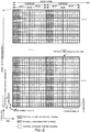
- Fig. 12 is a schematic diagram illustrating an example of a configuration of the radio frame of the downlink in an embodiment of the present invention.
- the horizontal axis indicates the time domain and the vertical axis indicates the frequency domain.
- the radio frame of the downlink includes a plurality of downlink physical resource block (PRB) pairs (a region surrounded by a broken line in Fig. 12 , for example).
- PRB physical resource block
- One downlink physical resource block pair includes two downlink physical resource blocks (PRB bandwidth ⁇ slot) contiguous in the time domain.
- One downlink physical resource block (a unit surrounded by a bold line in Fig. 12 ) includes 12 subcarriers (15 kHz) in the frequency domain and 7 OFDM (Orthogonal Frequency Division Multiplexing) symbols (71 ⁇ s) in the time domain.
- a slot (0.5 ms) composed of 7 OFDM symbols (71 ⁇ s)
- a subframe (1 ms) composed of 2 slots
- a radio frame (10 ms) composed of 10 subframes.
- the time interval of 1 ms which is the same as the subframe is also referred to as a transmit time interval (TTI).
- TTI transmit time interval
- a plurality of the downlink physical resource blocks is arranged in accordance with the bandwidth of the downlink.
- a unit composed of one subcarrier and one OFDM symbol is referred to as a downlink resource element.
- the PDCCH In each subframe of the downlink, the PDCCH, the PCFICH, the PHICH, the PDSCH, the downlink reference signal and the like are arranged.
- the PDCCH is arranged from the first OFDM symbol in the subframe (a hatched region in Fig. 12 ).
- the number of OFDM symbols in which the PDCCH is arranged is different for each subframe, and information indicating the number of OFDM symbols in each of which the PDCCH is arranged is broadcasted by the PCFICH.
- a plurality of PDCCHs is frequency-multiplexed and time-multiplexed.
- the PCFICH is arranged in the first OFDM symbol on the subframe and is frequency-multiplexed with the PDCCH.
- the PHICH is frequency-multiplexed with the PDCCH in the same OFDM symbol (a hatched region with reticulated lines in Fig. 12 ).
- the PHICH may be arranged only in the first OFDM symbol on the subframe or may be arranged in a distributed manner in a plurality of the OFDM symbols in each of which the PDCCH is arranged. In each subframe, a plurality of PHICHs is frequency-multiplexed and code-multiplexed.
- the mobile station apparatus 1 After a predetermined time from the transmission of the PUSCH (4 ms later, 4 subframes later or 4 TTIs later, for example), the mobile station apparatus 1 receives HARQ feedback for this PUSCH in the PHICH on the subframe of the downlink.
- PHICH on the subframe of the downlink the HARQ indicator for the PUSCH is arranged is determined based on a number of the physical resource block with the smallest number (in the lowest frequency domain) in the physical resource blocks assigned to this PUSCH and based on information included in the uplink grant and used for determining the cyclic shift used for the uplink reference signal which is time-multiplexed with the PUSCH.
- the PDSCH is arranged in the OFDM symbol (a non-hatched region in Fig. 12 ) other than the OFDM symbols in which the PDCCH, the PCFICH, and the PHICH are arranged in the subframe.
- the radio resource of the PDSCH is assigned by using the downlink assignment.
- the radio resources of the PDSCH and the PDCCH including the downlink assignment used for this assignment of the PDSCH in the time domain are arranged in the same subframe of the downlink. In each subframe, a plurality of the PDSCHs is frequency-multiplexed and space-multiplexed.
- the downlink reference signal is not shown in Fig. 12 for simplification of explanation, the downlink reference signal is arranged in a distributed manner in the frequency domain and the time domain.
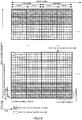
- Fig. 13 is a schematic diagram illustrating an example of a configuration of the radio frame of the uplink in an embodiment of the present invention.
- the horizontal axis indicates the time domain
- the vertical axis indicates the frequency domain.
- the uplink radio frame includes a plurality of uplink physical resource block pairs (a region surrounded by a broken line in Fig. 13 , for example) .
- One uplink physical resource block pair includes two uplink physical resource blocks (PRB bandwidth ⁇ slot) contiguous in the time domain.
- One uplink physical resource block (unit surrounded by a bold line in Fig. 13 ) includes 12 subcarriers (15 kHz) in the frequency domain and 7 SC-FDMA symbols (71 ⁇ s) in the time domain.
- a slot (0.5 ms) composed of 7 SC-FDMA (Single-Carrier Frequency Division Multiple Access) symbols (71 ⁇ s)
- a subframe (1 ms) composed of two slots
- a radio frame (10 ms) composed of 10 subframes.
- the time interval 1 ms which is the same as that of the subframe is also referred to as a Transmit Time Interval (TTI).
- TTI Transmit Time Interval
- a plurality of uplink physical resource blocks is arranged in accordance with the bandwidth of the uplink.
- a unit composed of one subcarrier and one SC-FDMA symbol is referred to as an uplink resource element.
- the physical channel assigned in the uplink radio frame will be described below.
- the PUCCH, PUCSH, PRACH, the uplink reference signal and the like are arranged in each subframe of the uplink.
- the PUCCH is arranged in the uplink physical resource block (a diagonally hatched region) at the both ends of the uplink band. In each subframe, a plurality of the PUCCHs is frequency-multiplexed and code-multiplexed.
- the PUSCH is arranged in the uplink physical resource block pair (a non-hatched region) other than the uplink physical resource block in which the PUCCH is arranged.
- the radio resource for the PUSCH is assigned by using the uplink grant and arranged in an uplink subframe after a predetermined time (4 ms after, 4 subframes after or 4 TTIs after, for example) from the downlink subframe in which the PDCCH including this uplink grant is arranged.
- a plurality of the PUSCHs is frequency-multiplexed and spatially-multiplexed.
- the uplink reference signal is time-multiplexed with the PUCCH or the PUSCH.
- the DMRS time-multiplexed with the PUSCH is arranged in the fourth and eleventh SC-FDMA symbols in the subframe.
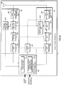
- Fig. 1 is a schematic block diagram illustrating a configuration of a mobile station apparatus 1 of an embodiment of the present invention.
- the mobile station apparatus 1 includes a higher-layer processing unit 101, a control unit 103, a reception unit 105, a transmission unit 107, and a transmission/reception antenna 109.
- the higher-layer processing unit 101 includes a radio resource control unit 1011 and a determination unit 1013.
- the reception unit 105 includes a decoding unit 1051, a demodulation unit 1053, a demultiplexing unit 1055, a radio reception unit 1057, and a channel measurement unit 1059.
- the transmission unit 107 includes an encoding unit 1071, a modulation unit 1073, a multiplexing unit 1075, a radio transmission unit 1077, and an uplink reference signal generation unit 1079.
- the higher-layer processing unit 101 outputs uplink data generated by an operation of a user and the like to the transmission unit 107. Moreover, the higher-layer processing unit 101 performs processing of a Medium Access Control (MAC) layer, a Packet Data Convergence Protocol (PDCP) layer, a Radio Link Control (RLC) layer and a Radio Resource Control (RRC) layer. Moreover, the higher-layer processing unit 101 generates control information for control of the reception unit 105 and the transmission unit 107 on the basis of the downlink control information received by the PDCCH and the like and outputs the control information to the control unit 103.
- MAC Medium Access Control
- PDCP Packet Data Convergence Protocol
- RLC Radio Link Control
- RRC Radio Resource Control
- the radio resource control unit 1011 provided in the higher-layer processing unit 101 manages various setting information of its own apparatus. For example, the radio resource control unit 1011 manages an RNTI such as a C-RNTI and an uplink transmission mode which will be described later. Moreover, the radio resource control unit 1011 generates information arranged in each channel of the uplink and outputs the information to the transmission unit 107.
- an RNTI such as a C-RNTI
- an uplink transmission mode which will be described later.
- the radio resource control unit 1011 generates information arranged in each channel of the uplink and outputs the information to the transmission unit 107.
- the determination unit 1013 provided in the higher-layer processing unit 101 determines whether or not the cyclic shift information included in the uplink grant corresponds to the OCC applied to the DMRS by using the uplink transmission mode, the RNTI and the like managed by the radio resource control unit 1011. Moreover, the determination unit 1013 determines the cyclic shift and the OCC applied to the DMRS in accordance with the cyclic shift information on the basis of the determination result, generates control information for the transmission unit 107 to apply the determined cyclic shift and OCC to the DMRS and outputs the control information to the control unit 103.
- the control unit 103 generates a control signal for controlling the reception unit 105 and the transmission unit 107 on the basis of the control information from the higher-layer processing unit 101.
- the control unit 103 outputs the generated control signal to the reception unit 105 and the transmission unit 107 and controls the reception unit 105 and the transmission unit 107.
- the reception unit 105 separates, demodulates, and decodes the received signal received from the base station apparatus 3 via the transmission/reception antenna 109 in accordance with the control signal input from the control unit 103 and outputs the decoded information to the higher-layer processing unit 101.
- the demultiplexing unit 1055 separates the extracted signal to the PHICH, the PDCCH, the PDSCH, and the downlink reference signal, respectively. This separation is made on the basis of assignment information of a radio resource notified by the downlink assignment and the like. Moreover, the demultiplexing unit 1055 compensates for the channels of the PHICH, PDCCH, and PDSCH on the basis of estimation values of the channels input from the channel measurement unit 1059. Moreover, the demultiplexing unit 1055 outputs the separated downlink reference signal to the channel measurement unit 1059.
- the demodulation unit 1053 multiplies and synthesizes a corresponding code to the PHICH, demodulates the synthesized signal in the Binary Phase Shift Keying (BPSK) modulation scheme, and outputs the result to the decoding unit 1051.
- the decoding unit 1051 decodes the PHICH addressed to its own apparatus and outputs a decoded HARQ indicator to the higher-layer processing unit 101.
- the demodulation unit 1053 demodulates the PDCCH in a QPSK demodulation scheme and outputs the result to the decoding unit 1051.
- the decoding unit 1051 tries blind decoding of the PDCCH and if the blind decoding is successful, outputs the decoded downlink control information and the RNTI included in the downlink control information to the higher-layer processing unit 101.
- the demodulation unit 1053 demodulates the PDSCH in a modulation scheme notified in the downlink assignment such as Quadrature Phase Shift keying (QPSK), 16QAM (Quadrature Amplitude Modulation), 64 QAM and the like and outputs the result to the decoding unit 1051.
- the decoding unit 1051 decodes the result on the basis of the information relating to the coding rate notified in the downlink control information and outputs the decoded downlink data (transport block) to the higher-layer processing unit 101.
- the channel measurement unit 1059 measures a path loss and a channel state of the downlink from the downlink reference signal input from the demultiplexing unit 1055 and outputs the measured path loss and channel state to the higher-layer processing unit 101. Moreover, the channel measurement unit 1059 calculates an estimation value of the downlink channel from the downlink reference signal and outputs the result to the demultiplexing unit 1055.
- the transmission unit 107 generates an uplink reference signal in accordance with the control signal input form the control unit 103, encodes and modulates the uplink data (transport block) input from the higher-layer processing unit 101, multiplexes the PUCCH, PUSCH, and the generated uplink reference signal, and transmits the result to the base station apparatus 3 via the transmission/reception antenna 109.
- the encoding unit 1071 performs coding on the uplink control information input from the higher-layer processing unit 101 such as convolutional coding, block coding and the like and performs turbo coding on the uplink data on the basis of the information relating to coding rate notified in the uplink grant.
- the modulation unit 1073 modulates the coding bit input from the encoding unit 1071 in a modulation scheme notified in the downlink control information such as BPSK, QPSK, 16QAM, 64QAM and the like or a modulation scheme determined in advance for each channel.
- the modulation unit 1073 maps sequences of modulation symbols of the plurality of pieces of uplink data transmitted by the same PUSCH by using the MIMO SM onto a plurality of sequences larger in number than the number of the pieces of the uplink data transmitted by the same PUSCH and performs precoding on these sequences on the basis of the number of sequences notified in the uplink grant and spatially multiplexed and the information indicating precoding to these sequences.
- the radio transmission unit 1077 performs Inverse Fast Fourier Transform (IFFT) on the multiplexed signal for modulation in the SC-FDMA system, adds the guard interval to the SC-FDMA modulated SC-FDMA symbol, generates a baseband digital signal, converts the baseband digital signal to an analog signal, generates an in-phase component and an orthogonal component of the intermediate frequency from the analog signal, removes an excess frequency component with respect to the intermediate frequency band, converts the signal with the intermediate frequency to a signal with a high frequency (up convert), removes an excess frequency component, amplifies power, and outputs the result to the transmission/reception antenna 109 for transmission.
- IFFT Inverse Fast Fourier Transform
- Fig. 2 is a schematic block diagram illustrating a configuration of the base station apparatus 3 of an embodiment of the present invention.
- the base station apparatus 3 includes a higher-layer processing unit 301, a control unit 303, a reception unit 305, a transmission unit 307, and a transmission/reception antenna 309.
- the higher-layer processing unit 301 includes a radio resource control unit 3011 and a downlink control information generation unit 3013.
- the reception unit 305 includes a decoding unit 3051, a demodulation unit 3053, a demultiplexing unit 3055, a radio reception unit 3057, and a channel measurement unit 3059.
- the transmission unit 307 includes an encoding unit 3071, a modulation unit 3073, a multiplexing unit 3075, a radio transmission unit 3077, and a downlink reference signal generation unit 3079.
- the higher-layer processing unit 301 performs processing of a Medium Access Control (MAC) layer, a Packet Data Convergence Protocol (PDCP) layer, a Radio Link Control (RLC) layer and a Radio Resource Control (RRC) layer. Moreover, the higher-layer processing unit 301 generates control information for control of the reception unit 305 and the transmission unit 307 and outputs the control information to the control unit 303.
- MAC Medium Access Control
- PDCP Packet Data Convergence Protocol
- RLC Radio Link Control
- RRC Radio Resource Control
- the radio resource control unit 3011 provided in the higher-layer processing unit 301 generates or obtains from a higher node, downlink data (transport block), an RRC signal, and an MAC CE (Control Element) arranged in the downlink PDSCH and outputs them to the transmission unit 307. Moreover, the radio resource control unit 3011 manages various types of setting information of each of the mobile station apparatuses 1. For example, the radio resource control unit 3011 performs management of the RNTI such as assignment of a C-RNTI to the mobile station apparatus 1 and of an uplink transmission mode set for the mobile station apparatus 1.
- the downlink control information generation unit 3013 provided in the higher-layer processing unit 301 generates downlink control information transmitted by the PDCCH.
- the downlink control information generation unit 3013 generates an uplink grant including the cyclic shift information corresponding to the OCC used for the DMRS and the uplink grant including the cyclic shift information not corresponding to the OCC used for the DMRS.
- the control unit 303 generates a control signal for controlling the reception unit 305 and the transmission unit 307 on the basis of the control information from the higher-layer processing unit 301.
- the control unit 303 outputs the generated control signals to the reception unit 305 and the transmission unit 307 and controls the reception unit 305 and the transmission unit 307.
- the reception unit 305 separates, demodulates, and decodes a received signal received from the mobile station apparatus 1 via the transmission/reception antenna 309 in accordance with the control signal input from the control unit 303 and outputs the decoded information to the higher-layer processing unit 301.
- the radio reception unit 3057 converts the uplink signal received via the transmission/reception antenna 309 to an intermediate frequency (down convert), removes an unnecessary frequency component, controls an amplification level so that the signal level is maintained appropriately, orthogonally demodulates the signal on the basis of an in-phase component and an orthogonal component of the received signal and converts the orthogonally-demodulated analog signal to a digital signal.
- the radio reception unit 3057 removes a portion corresponding to a guard interval (GI) from the converted digital signal.
- the radio reception unit 3057 performs Fast Fourier Transform (FFT) on the signal from which the GI has been removed, extracts a signal of the frequency domain, and outputs the result to the demultiplexing unit 3055.
- FFT Fast Fourier Transform
- the demultiplexing unit 3055 separates the signal input from the radio reception unit 3057 to the PUCCH, the PUSCH, a signal such as an uplink reference signal and the like. This separation is performed on the basis of assignment information of a radio resource included in the uplink grant determined by the base station apparatus 3 in advance in the radio resource control unit 3011 and notified to each mobile station apparatus 1. Moreover, the demultiplexing unit 3055 compensates for the channels of the PUCCH and PUSCH from estimation values of the channels input from the channel measurement unit 3059. Moreover, the demultiplexing unit 3055 outputs the separated uplink reference signal to the channel measurement unit 3059.
- the demodulation unit 3053 performs Inverse Discrete Fourier Transform (IDFT) on the PUSCH, obtains a modulation symbol, and demodulates a received signal for each of the modulation symbols of the PUCCH and the PUSCH using a modulation scheme determined in advance such as BPSK (Binary Phase Shift Keying), QPSK, 16QAM, 64QAM and the like or notified by its own apparatus in advance in the uplink grant for each of the mobile station apparatuses 1.
- BPSK Binary Phase Shift Keying
- QPSK Quadratureas Key
- 16QAM 16QAM
- 64QAM 64QAM
- the decoding unit 3051 decodes coding bits of the demodulated PUCCH and PUSCH with a coding rate determined in advance or notified in advance in the uplink grant by its own apparatus to the mobile station apparatus 1 in the coding method determined in advance and outputs the decoded uplink data and the uplink control information to the higher-layer processing unit 301.
- the decoding unit 3051 performs decoding by using the coding bit held in a HARQ buffer input from the higher-layer processing unit 301 and the demodulated coding bit.
- the channel measurement unit 3059 measures estimation values, a channel quality and the like of the channel from the uplink reference signal input from the demultiplexing unit 3055 and outputs the result to the demultiplexing unit 3055 and the higher-layer processing unit 301.
- the transmission unit 307 generates a downlink reference signal in accordance with the control signal input from the control unit 303, encodes and modulates the HARQ indicator, downlink control information, and the downlink data input from the higher-layer processing unit 301, multiplexes the PHICH, PDCCH, PDSCH, and the downlink reference signal, and transmits the result to the mobile station apparatus 1 via the transmission/reception antenna 309.
- the encoding unit 3071 performs coding on the HARQ indicator, the downlink control information, and the downlink data input from the higher-layer processing unit 301 by using a coding method determined in advance such as block coding, convolutional coding, turbo coding and the like or performs coding by using a coding method determined by the radio resource control unit 3011.
- the modulation unit 3073 modulates the coding bits input from the encoding unit 3071 by a modulation scheme determined in advance such as BPSK, QPSK, 16QAM, 64QAM and the like or determined by the radio resource control unit 3011.
- the radio transmission unit 3077 performs Inverse Fast Fourier Transform (IFFT) on the multiplexed modulation symbol and the like for performing modulation in the OFDM system, adds the guard interval to the OFDM-modulated OFDM symbol, generates a baseband digital signal, converts the baseband digital signal to an analog signal, generates an in-phase component and an orthogonal component of the intermediate frequency from the analog signal, removes an excess frequency component with respect to the intermediate frequency band, converts the signal with the intermediate frequency to a signal with a high frequency (up convert), removes an excess frequency component, amplifies power, and outputs the result to the transmission/reception antenna 309 for transmission.
- IFFT Inverse Fast Fourier Transform
- Fig. 3 is a schematic diagram for explaining a generating method of the DMRS in an embodiment of the present invention.
- the horizontal axis is the time domain.
- Step S103 the CAZAC sequence multiplied by the OCC is mapped onto the physical resource block to which the PUSCH is assigned, Inverse Fast Fourier Transform (IFFT) is executed, and an SC-FDMA symbol is generated (Step S103).
- the generated SC-FDMA symbol is mapped as fourth and eleventh SC-FDMA symbols in the subframe.
- Multiplication of the OCC at [1, 1] corresponds to non-application of the OCC to the DMRS (Step S102 is omitted).
- non-application of the OCC (Step S102 is omitted) corresponds to multiplication of the OCC at [1, 1] .
- Fig. 4 is a schematic diagram illustrating an example of a configuration of the search space in which the PDCCH of is arranged in an embodiment of the present invention.
- the horizontal axis indicates a number identifying a Control Channel Element (CCE) .
- CCE Control Channel Element
- a unit surrounded by a bold line in Fig. 4 is a candidate in which the PDCCH is to be arranged (hereinafter referred to as "PDCCH candidate") composed of a plurality of continuously-numbered control channel elements.
- the PDCCH candidate diagonally hatched in Fig. 4 is a PDCCH candidate in a mobile station apparatus specific search space (UE-specific Search Space: USS).
- the PDCCH candidate hatched in a reticulated state in Fig. 4 is a PDCCH candidate in a Common Search Space (CSS).
- CCSS Common Search Space
- the common search space is a space common among a plurality of the mobile station apparatuses 1 and is a space in which the PDCCH to a plurality of mobile station apparatuses 1 and/or the PDCCH to a specific mobile station apparatus 1 are/is arranged.
- the mobile station apparatus specific search space is a space in which the PDCCH to the specific mobile station apparatus 1 is arranged and is a space configured for each mobile station apparatus 1.
- the search space is a set of the PDCCH candidates.
- the PDCCH candidate is composed of a plurality of Control Channel Elements (CCE).
- One control channel element is composed of a plurality of resource elements dispersed in a frequency domain and a time domain within the OFDM symbol in which the PDCCH in the same subframe is arranged.
- a different search space is configured for each number of the control channel elements constituting the PDCCH candidate.
- different common search spaces are configured for the PDCCH candidate constituted by four control channel elements and the PDCCH candidate constituted by eight control channel elements.
- different mobile station apparatus specific search spaces are configured for the PDCCH candidate constituted by one control channel element, the PDCCH candidate constituted by two control channel elements, the PDCCH candidate constituted by four control channel elements, and the PDCCH candidate constituted by eight channel elements.
- the common search space is configured by zeroth to fifteenth control channel elements.
- the number of PDCCH candidates and the number of control channel elements constituting the mobile station apparatus specific search space are determined in advance, and the number of the control channel element constituting the mobile station apparatus specific search space is determined by hushing function using the C-RNTI assigned by the base station apparatus 3 to the mobile station apparatus 1 as an input.
- the mobile station apparatus specific search space is constituted by control channel elements different for each subframe.
- a part of or the whole of the different mobile station apparatus specific search spaces may be duplicated for the different mobile station apparatus 1.
- the plurality of mobile station apparatus specific search spaces and the plurality of common search spaces constituted by the different numbers of the control channel elements for the same mobile station apparatus 1 may be constituted by the same control channel element or may be constituted by the different control channel elements. That is, a part of or the whole of the PDCCH candidates constituting the different plurality of search spaces may be duplicated.
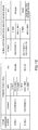
- Fig. 5 is a diagram illustrating a relationship between the uplink grant and the OCC applied to the DMRS in an embodiment of the present invention.
- the mobile station apparatus 1 of the present invention includes a mode 1 not using the OCC for the DMRS time-multiplexed with the PUSCH and a mode 2 using the OCC for the DMRS time-multiplexed with the PUSCH as the uplink transmission mode.
- the uplink transmission mode of the mobile station apparatus 1 is set by the base station apparatus 3.
- the base station apparatus 3 notifies the mobile station apparatus 1 of information indicating the set uplink transmission mode by using an RRC (Radio Resource Control) signal or the like.
- the RRC signal is information used for control of radio resources and transmitted by the PDSCH.
- the mobile station apparatus 1 performs blind decoding for the DCI format 0 including the C-RNTI, the DCI format 0 including the SPS C-RNTI, and the DCI format 0 including the T C-RNTI in the uplink transmission mode 1 in the common search space and performs blind decoding for the DCI format 0 including the C-RNTI and the DCI format 0 including the SPS C-RNTI in the mobile station apparatus specific search space.
- the mobile station apparatus 1 in the mode 2 performs blind decoding for the DCI format 0 including the C-RNTI, the DCI format 0 including the SPS C-RNTI, and the DCI format 0 including the T C-RNTI in the common search space and performs blind decoding for the DCI format 0 and the DCI format 0A including the C-RNTI and the DCI format 0 and the DCI format 0A including the SPS C-RNTI in the mobile station apparatus specific search space.
- the mobile station apparatus 1 in the mode 2 determines whether the OCC is valid or invalid on the basis of which of the RNTI is included in the uplink grant (in the DCI format 0 and the DCI format 0A). The mobile station apparatus 1 in the mode 2 determines that the OCC is valid if the C-RNTI is included in the uplink grant.
- the mobile station apparatus 1 in the mode 2 determines that the OCC is valid. If the uplink grant including the SPS C-RNTI does not instruct to retransmit, the mobile station apparatus 1 in the mode 2 determines that the OCC is invalid.
- a value of an NDI of this uplink grant is set to one. If the uplink grant including the SPS C-RNTI instructs to perform activation (or initiation), resetting or release of assignment of the permanently assigned PUSCH, the value of the NDI of this uplink grant is set to zero.
- the uplink grant including the SPS C-RNTI does not instruct to retransmit, that is, if the value of the NDI is zero
- the cyclic shift information included in the uplink grant is set to a specific code point ('000', for example) .
- the period of the radio resource of the PUSCH permanently assigned to the mobile station apparatus 1 or the like is notified from the base station apparatus 3 to the mobile station apparatus 1 in advance by the RRC signal.
- the T C-RNTI is used for instructing the mobile station apparatus 1 to perform retransmission of the random access message 3.
- the base station apparatus 3 failed in decoding the message 3 including the information for identifying the mobile station apparatus 1, the base station apparatus 3 cannot recognize which mobile station apparatus 1 has transmitted the message 3.
- the mobile station apparatus 1 in the mode 1 invalidates the OCC and performs retransmission of the message 3 and the mobile station apparatus 1 in the mode 2 validates the OCC and transmits the message 3, since the base station apparatus 3 cannot determine whether or not the OCC is applied to the DMRS time-multiplexed with the PUSCH of the message 3 and transmitted, the channel compensation cannot be correctly performed on the PUSCH, and whereby a problem that reception of the message 3 fails is caused.
- the mobile station apparatus 1 in the mode 2 determines that the OCC is invalid if the T C-RNTI is included in the DCI format 0 and makes transmission without applying the OCC to the DMRS when retransmitting the message 3. Moreover, the mobile station apparatus 1 also makes transmission without applying the OCC to the DMRS when making initial transmission of the message 3 on the radio resource assigned by a random access response for the random access preamble transmitted by its own apparatus. As a result, the base station apparatus 3 can correctly receive the message 3 by determining that the OCC is never used in the message 3.
- the DCI format 0 or only the DCI format 0A may be arranged as the uplink grant.
- the DCI format other than the DCI formats illustrated in Fig. 5 may be arranged or the DCI format including the RNTI other than the RNTI illustrated in Fig. 5 may be arranged.
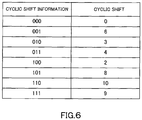
- Fig. 6 is a diagram illustrating the relationship between the cyclic shift information and the cyclic shift applied to the DMRS when the mobile station apparatus 1 of an embodiment of the present invention determines that the OCC is invalid.
- the mobile station apparatus 1 determines that the OCC is invalid, it selects only a parameter for determining the cyclic shift to be applied to the DMRS on the basis of the cyclic shift information.
- Fig. 7 is a diagram illustrating the relationship between the cyclic shift information and the cyclic shift applied to the DMRS when the mobile station apparatus 1 of an embodiment of the present invention determines that the OCC is valid.
- the mobile station apparatus 1 determines that the OCC is valid, it selects the parameter for determining the cyclic shift to be applied to the DMRS and the OCC to be applied to the DMRS on the basis of the cyclic shift information.
- the mobile station apparatus 1 changes setting of the uplink transmission mode of the mobile station apparatus 1 and notifies the mobile station apparatus 1 to change the setting of the uplink transmission mode by the RRC signal, the mobile station apparatus 1 changes the uplink transmission mode after a certain time has elapsed since reception of this RRC signal. After changing the uplink transmission mode, the mobile station apparatus 1 notifies the base station apparatus 3 of a message notifying that the change of the uplink transmission mode is completed.
- the base station apparatus 3 cannot know when the mobile station apparatus 1 changed the uplink transmission mode for a period from notification of a change of the uplink transmission mode to the mobile station apparatus 1 by the RRC signal to reception of the message from the mobile station apparatus 1 notifying that the change of the uplink transmission mode is completed, a period during which the uplink transmission mode of the mobile station apparatus 1 cannot be grasped is generated.
- the base station apparatus 3 in a period during which the base station apparatus 3 cannot grasp the uplink transmission mode of the mobile station apparatus 1, the base station apparatus 3 includes the cyclic shift information having a value corresponding to the OCC at [1, 1] having the same DMRS when the OCC is invalidated in the DCI format and transmits the result to the mobile station apparatus 1 in the mode 2.
- the cyclic shift information having values of "000”, "001", "011", and "110" corresponds to the OCC at [1, 1].
- the mobile station apparatus 1 uses only the OCC at [1, 1] having the same DMRS when the OCC is invalidated, and thus, regardless of the uplink transmission mode of the mobile station apparatus 1, the base station apparatus 3 can correctly receive the PUSCH by performing reception processing of the PUSCH, assuming that the mobile station apparatus 1 is not using the OCC.
- the base station apparatus 3 does not know the uplink transmission mode of the mobile station apparatus 1 when the mobile station apparatus 1 makes an initial access to the base station apparatus 3, the base station apparatus 3 cannot correctly receive the PUSCH transmitted by the mobile station apparatus 1, and thus, a default uplink transmission mode needs to be determined.
- the uplink transmission mode of the mobile station apparatus 1 when the mobile station apparatus 1 makes an initial access to the base station apparatus 3 is set to the mode 1 whose transmission processing of the DMRS is easy.
- Fig. 8 is a flowchart illustrating an example of the operation of the mobile station apparatus 1 of an embodiment of the present invention.
- the mobile station apparatus 1 sets the uplink transmission mode notified from the base station apparatus 3 (Step S200).
- the mobile station apparatus 1 performs blind decoding of the uplink grant and detects the uplink grant (Step S201).
- the mobile station apparatus 1 determines whether the uplink transmission mode of its own apparatus is the mode 1 or the mode 2 (Step S202) . If the mobile station apparatus 1 determines that the uplink transmission mode of its own apparatus is the mode 2, it determines whether the OCC is to be applied to the DMRS on the basis of the RNTI included in the uplink grant (Step S203).
- the mobile station apparatus 1 determines the OCC and the cyclic shift to be applied to the DMRS on the basis of the cyclic shift information in the uplink grant (Step S204).
- the mobile station apparatus 1 determines only the cyclic shift to be applied to the DMRS on the basis of the cyclic shift information in the uplink grant (Step S205).
- Step S202 If the mobile station apparatus 1 determines that the uplink transmission mode of its own apparatus is the mode 1 at Step S202, the routine proceeds to Step S205.
- the mobile station apparatus 1 applies the cyclic shift and the OCC, as necessary, determined at Step S204 or Step S205 to the DMRS, time-multiplexes the DMRS and PUSCH and transmits the result (Step S206).
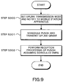
- Fig. 9 is a flowchart illustrating an example of an operation of the base station apparatus 3 of an embodiment of the present invention.
- the base station apparatus 3 notifies the mobile station apparatus 1 of the transmission mode set for the mobile station apparatus 1 by using the RRC signal or the like (Step S300).
- the base station apparatus 3 schedules the PUSCH and transmits the uplink grant indicating the radio resource for the scheduled PUSCH to the mobile station apparatus 1 (Step S301).
- the base station apparatus 3 includes the cyclic shift information corresponding only to the parameter for determining the cyclic shift used for the DMRS in the uplink grant corresponding to the mobile station apparatus 1 set to the mode 1.
- the base station apparatus 3 includes the cyclic shift information corresponding only to the parameter for determining the cyclic shift used for the DMRS in the uplink grant assigning the radio resource of the PUSCH used for retransmitting the message 3 including T C-RNTI.
- the base station apparatus 3 includes the cyclic shift information corresponding to the parameter for determining the cyclic shift used for the DMRS and the OCC used for the DMRS in the uplink grant including C-RNTI corresponding to the mobile station apparatus 1 set to the mode 2.
- the base station apparatus 3 includes the cyclic shift information corresponding to the parameter for determining the cyclic shift used for the DMRS and the OCC used for the DMRS in the uplink grant including the SPS C-RNTI and ordering retransmission of the PUSCH corresponding to the mobile station apparatus 1 set to the mode 2.
- the base station apparatus 3 includes the cyclic shift information corresponding only to the parameter for determining the cyclic shift used for the DMRS in the uplink grant including the SPS C-RNTI and not ordering retransmission of the PUSCH corresponding to the mobile station apparatus 1 set to the mode 2.
- the base station apparatus 3 receives the PUSCH and the DMRS in compliance with the uplink grant transmitted to the mobile station apparatus 1 at Step S301, performs channel compensation of the PUSCH by using the DMRS, and executes decoding processing of the PUSCH (Step S302).
- the base station apparatus 3 transmits the uplink grant (first control information) including the cyclic shift information corresponding to the parameter for determining the cyclic shift used for the DMRS (reference signal) time-multiplexed with the PUSCH (data channel) and transmitted by the mobile station apparatus 1 and the uplink grant (second control information) including the above-described cyclic shift information corresponding to the parameter for determining the cyclic shift used for the DMRS and the OCC (diffusion code) used for the DMRS by including different RNTI (identifier) therein.
- first control information including the cyclic shift information corresponding to the parameter for determining the cyclic shift used for the DMRS (reference signal) time-multiplexed with the PUSCH (data channel) and transmitted by the mobile station apparatus 1
- the uplink grant (second control information) including the above-described cyclic shift information corresponding to the parameter for determining the cyclic shift used for the DMRS and the OCC (diffusion code) used for the DM
- the mobile station apparatus 1 determines by the RNTI included in the detected uplink grant whether the cyclic shift information included in the detected uplink grant corresponds to the parameter for determining the cyclic shift used for the DMRS time-multiplexed with the PUSCH and the OCC used for the DMRS or corresponds only to the parameter for determining the cyclic shift used for the DMRS time-multiplexed with the PUSCH.
- the base station apparatus 3 can accurately recognize whether or not the mobile station apparatus 1 applies the OCC to the DMRS time-multiplexed with the PUSCH, and thus, the base station apparatus 3 can correctly perform channel compensation of the PUSCH by using the DMRS and decode the PUSCH.
- the base station apparatus 3 arranges the uplink grant (first control information) including the cyclic shift information corresponding only to the parameter for determining the cyclic shift used for the DMRS in the common search space (first search space) and arranges the uplink grant (second control information) including the cyclic shift information corresponding to the parameter for determining the cyclic shift used for the DMRS and the OCC used for the DMRS in the mobile station apparatus specific search space (second search space).
- the mobile station apparatus 1 discriminates whether the cyclic shift information included in the detected uplink grant corresponds only to the parameter for determining the cyclic shift used for the DMRS or corresponds to the parameter for determining the cyclic shift used for the DMRS and the OCC used for the DMRS on the basis of which of the common search space and the mobile station apparatus specific search space the uplink grant is detected in.
- Fig. 10 is a diagram illustrating a relationship between the uplink grant and the OCC applied to the DMRS in the second embodiment of the present invention.
- the mobile station apparatus 1 of the second embodiment includes the mode 1 not using the OCC for the DMRS time-multiplexed with the PUSCH and the mode 2 using the OCC for the DMRS time-multiplexed with the PUSCH as the uplink transmission mode.
- the mobile station apparatus 1 performs blind decoding in the DCI format 0 including the C-RNTI, the DCI format 0 including the SPS C-RNTI, and the DCI format 0 including the T C-RNTI in the common search space and performs blind decoding in the DCI format 0 including the C-RNTI and the DCI format 0 including the SPS C-RNTI in the mobile station apparatus specific search space in the uplink transmission mode 1. In mode 1, whichever of the search spaces the DCI format 0 is detected, the OCC is invalid.
- the mobile station apparatus 1 in the uplink transmission mode 2 performs blind decoding in the DCI format 0 including the C-RNTI, the DCI format 0 including the SPS C-RNTI, and the DCI format 0 including the T C-RNTI in the common search space and performs blind decoding in the DCI format 0 and the DCI format 0A including the C-RNTI and the DCI format 0 and the DCI format 0A including the SPS C-RNTI in the mobile station apparatus specific search space.
- the mobile station apparatus 1 in the mode 2 determines whether the OCC is valid or invalid on the basis of which of the common search space or the mobile station apparatus specific search space the DCI format 0 and the DCI format 0A are detected in. The mobile station apparatus 1 in the mode 2 determines that the OCC is invalid if the DCI format 0 is detected in the common search space. The mobile station apparatus 1 in the mode 2 determines that the OCC is valid if the DCI format 0 and the DCI format 0A including the C-RNTI are detected in the mobile station apparatus specific search space. Since the mobile station apparatus 1 in the mode 2 monitors the DCI format 0A only in the mobile station apparatus specific search space, the DCI format 0A has the OCC valid all the time.
- the mobile station apparatus 1 in the mode 2 determines that the OCC is valid if the DCI format 0 and the DCI format 0A including the SPS C-RNTI and ordering retransmission are detected in the mobile station apparatus specific search space.
- the mobile station apparatus 1 in the mode 2 determines that the OCC is invalid if the DCI format 0 and the DCI format 0A including the SPS C-RNTI and not ordering retransmission are detected in the mobile station apparatus specific search space.
- the mobile station apparatus 1 cannot determine whether the DCI format 0 detected in the overlapped space is arranged in the common search space and the OCC is invalid or it is arranged in the mobile station apparatus specific search space and the OCC is valid.
- the overlap of the common search space and the mobile station apparatus specific search space means that the PDCCH candidates constituting the common search space and the PDCCH candidates constituting the mobile station apparatus specific search space are all composed of the same control channel elements.
- the PDCCH candidate composed of eighth to fifteenth control channel elements is a space where the common search space and the mobile station apparatus specific search space are overlapped.
- the mobile station apparatus 1 determines that it is the DCI format to be arranged in the search space determined in advance.
- the DCI format 0 is detected in the space where the common search space and the mobile station apparatus specific search space are overlapped, for example, it is determined in advance that the DCI format 0 is to be arranged in the common search space and the mobile station apparatus 1 determines that the OCC is invalid.
- the mobile station apparatus 1 determines that the OCC is invalid all the time regardless of the uplink transmission mode by using the DCI format 0 arranged in the common search space and thus, the base station apparatus 3 can correctly recognize whether or not the mobile station apparatus 1 applies the OCC to the DMRS time-multiplexed with the PUSCH.
- the base station apparatus 3 can perform radio communication with the mobile station apparatus 1 by using the uplink grant including the C-RNTI in the common search space in the above period, the OCC of the uplink grant including the SPS C-RNTI in the common search space may be made valid.
- the radio communication system of the present invention is a radio communication system in which the base station apparatus and the mobile station apparatus perform radio communication with each other, wherein the base station apparatus includes the cyclic shift information corresponding to the parameter for determining the cyclic shift used for the reference signal transmitted from the mobile station apparatus in the first control information, includes the cyclic shift information corresponding to the parameter for determining the cyclic shift used for the reference signal and the spread code used for the reference signal in the second control information and transmits the first control information or the second control information to the mobile station apparatus, while the mobile station apparatus applies only the cyclic shift to the reference signal in case that the first control information was detected, applies the cyclic shift and the spread code to the reference signal and transmits the reference signal in case that the second control information was detected.
- the base station apparatus includes the first RNTI in the first control information and includes the second RNTI in the second control information, while the mobile station apparatus discriminates whether the detected control information is the first control information or the second control information on the basis of whether the detected control information includes the first RNTI or the second RNTI.
- the base station apparatus sets the first mode in which the mobile station apparatus is made to monitor only the first control information or the second mode in which the mobile station apparatus is made to monitor at least the second control information and transmits only the cyclic shift information corresponding to the spread signal at [1, 1] included in the second control information for a period from notification of the setting to the mobile station apparatus to reception of the message notifying that the setting is completed from the mobile station apparatus.
- the base station apparatus arranges the first control information in the first search space and arranges the second control information in the second search space, while the mobile station apparatus discriminates which of the first control information and the second control information is the detected control information on the basis of which of the first search space and the second search space the control information is detected in.
- the base station apparatus arranges only the first control information or second control information, while, if the control information is detected in the overlapped space, the mobile station apparatus determines that the first control information or the second control information is detected.
- the base station apparatus of the present invention is a base station apparatus that performs radio communication with the mobile station apparatus, wherein the base station apparatus includes the cyclic shift information corresponding to the parameter for determining the cyclic shift used for the reference signal transmitted by the mobile station apparatus in the first control information, includes the parameter for determining the cyclic shift used for the reference signal and the cyclic shift information corresponding to the spread code used for the reference signal in the second control information, and transmits the first control information or the second control information to the mobile station apparatus.
- the mobile station apparatus of the present invention is a mobile station apparatus that performs radio communication with the base station apparatus, wherein, in case that the first control information including the cyclic shift information corresponding to the parameter for determining the cyclic shift used for the reference signal transmitted by its own apparatus was detected, the mobile station apparatus applies only the cyclic shift to the reference signal, while in case that the second control information including the parameter for determining the cyclic shift used for the reference signal and the cyclic shift information corresponding to the spread code used for the reference signal was detected, the cyclic shift and the spread code are applied to the reference signal, and the reference signal is transmitted.
- the radio communication method of the present invention is a radio communication method used in the base station apparatus that performs radio communication with the mobile station apparatus and includes the steps of including the cyclic shift information corresponding to the parameter for determining the cyclic shift used for the reference signal transmitted by the mobile station apparatus in the first control information, including the parameter for determining the cyclic shift used for the reference signal and the cyclic shift information corresponding to the spread code used for the reference signal in the second control information, and transmitting the first control information or the second control information to the mobile station apparatus.
- the radio communication method of the present invention is a radio communication method used in the mobile station apparatus that performs radio communication with the base station apparatus and includes the steps of applying, if the first control information including the cyclic shift information corresponding to the parameter for determining the cyclic shift used for the reference signal transmitted by its own apparatus was detected, only the cyclic shift to the reference signal, applying, if the second control information including the parameter for determining the cyclic shift used in the reference signal and the cyclic shift information corresponding to the spread code used for the reference signal was detected, the cyclic shift and the spread code to the reference signal, and transmitting the reference signal.
- the integrated circuit of the present invention is an integrated circuit used in the base station apparatus that performs radio communication with the mobile station apparatus and includes functions of including the cyclic shift information corresponding to the parameter for determining the cyclic shift used for the reference signal transmitted by the mobile station apparatus in the first control information, including the parameter for determining the cyclic shift used for the reference signal and the cyclic shift information corresponding to the spread code used for the reference signal in the second control information, and transmitting the first control information or the second information to the mobile station apparatus.
- the integrated circuit of the present invention is an integrated circuit used in the mobile station apparatus that performs radio communication with the base station apparatus and includes functions applying, if the first control information including the cyclic shift information corresponding to the parameter for determining the cyclic shift used for the reference signal transmitted by its own apparatus was detected, only the cyclic shift to the reference signal, applying, if the second control information including the parameter for determining the cyclic shift used in the reference signal and the cyclic shift information corresponding to the spread code used for the reference signal was detected, the cyclic shift and the spread code to the reference signal, and transmitting the reference signal.
- the program operated in the base station apparatus 3 and the mobile station apparatus 1 relating to the present invention may be a program (a program for having a computer function) for controlling the CPU (Central Processing Unit) and the like so that the functions of the above-described embodiment relating to the present invention are realized.
- the information handled by these apparatuses is temporarily stored in a RAM (Random Access Memory) during the processing thereof, and then, stored in various ROMs such as a Flash ROM (Read Only Memory) and HDDs (Hard Disk Drive), and read out, modified/written by the CPU as necessary.
- a part of the mobile station apparatus 1 and the base station apparatus 3 in the above-described embodiment may be realized by a computer.
- the program for realizing the control function is recorded in a computer-readable recording medium, and the program recorded in the recording medium may be read in and executed by the computer system so as to be realized.
- the "computer system” here means a computer system incorporated in the mobile station apparatus 1 or the base station apparatus 3 and is assumed to include OS and hardware such as peripheral equipment.
- the "computer-readable recording medium” refers to a portable medium such as a flexible disk, a magneto optical disk, a ROM, a CD-ROM and the like and a storage device such as a hard disk incorporated in the computer system.
- the "computer-readable recording medium” may include those holding the program dynamically for a short time such as a communication line when the program is transmitted through a communication line such as a network including the Internet and a telephone line and the like and those holding the program for a given time such as a volatile memory inside the computer system which becomes a server and a client in that case.
- the above-described programs may be such as to realize a part of the above-described functions or may be able to be realized by a combination with the program already recorded in the computer system.
- a part of or the whole of the mobile station apparatus 1 and the base station apparatus 3 in the above-described embodiment may be realized as an LSI which is typically an integrated circuit or may be realized as a chip set.
- Each functional block of the mobile station apparatus 1 and the base station apparatus 3 may be individually made into a chip or a part of or the whole of them may be integrated and made into a chip.
- a method of making them into an integrated circuit is not limited to the LSI but may be realized by a dedicated circuit or a general-purpose processor.
- the integrated circuit by that technology can be also used.
Landscapes
- Engineering & Computer Science (AREA)
- Signal Processing (AREA)
- Computer Networks & Wireless Communication (AREA)
- Power Engineering (AREA)
- Quality & Reliability (AREA)
- Mobile Radio Communication Systems (AREA)
- Digital Transmission Methods That Use Modulated Carrier Waves (AREA)
Applications Claiming Priority (2)
| Application Number | Priority Date | Filing Date | Title |
|---|---|---|---|
| JP2010121258A JP4928621B2 (ja) | 2010-05-27 | 2010-05-27 | 無線通信システム、基地局装置、移動局装置、無線通信方法および集積回路 |
| PCT/JP2011/061679 WO2011148876A1 (ja) | 2010-05-27 | 2011-05-20 | 移動局装置、基地局装置、無線通信システム、無線通信方法および集積回路 |
Publications (3)
| Publication Number | Publication Date |
|---|---|
| EP2579661A1 EP2579661A1 (en) | 2013-04-10 |
| EP2579661A4 EP2579661A4 (en) | 2015-01-07 |
| EP2579661B1 true EP2579661B1 (en) | 2018-07-25 |
Family
ID=45003866
Family Applications (1)
| Application Number | Title | Priority Date | Filing Date |
|---|---|---|---|
| EP11786575.8A Active EP2579661B1 (en) | 2010-05-27 | 2011-05-20 | Mobile station apparatus, base station apparatus, wireless communication system, wireless communication method and integrated circuit |
Country Status (12)
Families Citing this family (69)
| Publication number | Priority date | Publication date | Assignee | Title |
|---|---|---|---|---|
| US9591664B2 (en) * | 2011-02-21 | 2017-03-07 | Lg Electronics Inc. | Method for setting search space for relay node in wireless communication system and device therefor |
| EP2745609A4 (en) * | 2011-09-09 | 2015-06-10 | Nokia Corp | METHOD AND DEVICE FOR LAN IMPLEMENTATION |
| CN102439870B (zh) * | 2011-10-17 | 2014-07-09 | 华为技术有限公司 | 一种实现微波多输入多输出的方法、设备和系统 |
| US20130128821A1 (en) * | 2011-11-18 | 2013-05-23 | Nokia Siemens Networks Oy | Demodulation Reference Signal Arrangement For Uplink Coordinated Multi-Point Reception |
| US9686110B2 (en) | 2012-02-20 | 2017-06-20 | Lg Electronics Inc. | Method and apparatus for transmitting uplink signal in wireless communication system |
| WO2013125846A1 (en) | 2012-02-20 | 2013-08-29 | Lg Electronics Inc. | Method and apparatus for transmitting uplink signal in wireless communication system |
| WO2013125839A1 (en) | 2012-02-20 | 2013-08-29 | Lg Electronics Inc. | Method and apparatus for transmitting uplink signal in wireless communication system |
| JP5379254B2 (ja) * | 2012-03-14 | 2013-12-25 | シャープ株式会社 | 移動局装置、基地局装置、通信方法、集積回路および無線通信システム |
| JP5379255B2 (ja) * | 2012-03-14 | 2013-12-25 | シャープ株式会社 | 移動局装置、基地局装置、通信方法、集積回路および無線通信システム |
| JP5314779B2 (ja) * | 2012-03-14 | 2013-10-16 | シャープ株式会社 | 移動局装置、基地局装置、通信方法、集積回路および無線通信システム |
| JP5379256B2 (ja) | 2012-03-14 | 2013-12-25 | シャープ株式会社 | 移動局装置、基地局装置、通信方法、集積回路および無線通信システム |
| JP6045843B2 (ja) * | 2012-07-31 | 2016-12-14 | 株式会社Nttドコモ | 通信システム、基地局装置、移動端末装置及び通信方法 |
| CN103781177B (zh) * | 2012-10-19 | 2018-10-30 | 株式会社Ntt都科摩 | 一种信息传输方法、装置及基站 |
| GB2507531B (en) * | 2012-11-02 | 2015-05-06 | Broadcom Corp | Common search space configuration of a carrier |
| JP5883403B2 (ja) * | 2013-01-31 | 2016-03-15 | 株式会社Nttドコモ | ユーザ端末、無線基地局、及び無線通信方法 |
| CN105122712B (zh) * | 2013-03-15 | 2019-06-04 | Lg 电子株式会社 | 在无线通信系统中接收ack/nack的方法和设备 |
| US9955467B2 (en) * | 2013-06-27 | 2018-04-24 | Telefonaktiebolaget L M Ericsson (Publ) | Method and BS for transmitting control information to UE, and method and UE for handling control information |
| US9479298B2 (en) * | 2013-07-08 | 2016-10-25 | Intel IP Corporation | Demodulation reference signals (DMRS)for side information for interference cancellation |
| CN106233794A (zh) * | 2014-01-29 | 2016-12-14 | 交互数字专利控股公司 | 用于覆盖增强无线传输的接入和链路自适应的方法 |
| JP6588037B2 (ja) | 2014-02-10 | 2019-10-09 | エルジー エレクトロニクス インコーポレイティド | 無線通信システムにおけるd2d通信のための信号送信方法及びそのための装置 |
| JP6723150B2 (ja) * | 2014-03-20 | 2020-07-15 | シャープ株式会社 | 端末装置および集積回路 |
| US10264571B2 (en) * | 2015-01-29 | 2019-04-16 | Lg Electronics Inc. | Uplink control information reception method and user equipment, and downlink control information transmission method and base station |
| CN105991245A (zh) * | 2015-01-30 | 2016-10-05 | 中兴通讯股份有限公司 | 一种信息传输方法、设备及系统 |
| MX367287B (es) * | 2015-02-06 | 2019-08-13 | Panasonic Ip Corp America | Dispositivo de comunicacion y metodo de comunicacion. |
| US10757664B2 (en) * | 2015-05-14 | 2020-08-25 | Apple Inc. | Contention free physical uplink shared control channel (PUSCH) transmission using listen before talk |
| WO2017024582A1 (zh) * | 2015-08-13 | 2017-02-16 | 华为技术有限公司 | 上行参考信号传输方法、用户终端及基站 |
| EP3375233B1 (en) * | 2015-09-24 | 2020-02-05 | Telefonaktiebolaget LM Ericsson (PUBL) | Technique for downlink control |
| WO2017078185A1 (ko) * | 2015-11-02 | 2017-05-11 | 엘지전자 주식회사 | 무선통신 시스템에서 비연결 기반 전송을 수행하는 방법 및 이를 위한 장치 |
| US10419173B2 (en) * | 2015-11-23 | 2019-09-17 | Electronics And Telecommunications Research Institute | Method and apparatus for transmitting uplink signal using a short transmit time interval |
| JP6290852B2 (ja) * | 2015-12-24 | 2018-03-07 | 日本電気株式会社 | 信号構成装置、信号構成システム、信号構成方法、および信号構成用プログラム |
| CN112910607A (zh) * | 2016-01-11 | 2021-06-04 | 中兴通讯股份有限公司 | 上行控制信息的发送方法及装置 |
| CN107295624B (zh) * | 2016-03-30 | 2021-11-26 | 日本电气株式会社 | 节点同步方法和采用该方法的节点 |
| EP4216645A1 (en) * | 2016-04-01 | 2023-07-26 | LG Electronics Inc. | Method for transmitting downlink control information for sidelink scheduling in wireless communication system and terminal using same |
| US11395325B2 (en) | 2016-04-01 | 2022-07-19 | Lg Electronics Inc. | Method for transmitting downlink control information for sidelink scheduling in wireless communication system and terminal using same |
| JP2019517182A (ja) | 2016-04-20 | 2019-06-20 | コンヴィーダ ワイヤレス, エルエルシー | ダウンリンク同期 |
| EP3446515B1 (en) | 2016-04-20 | 2020-12-02 | Convida Wireless, LLC | System information provisioning |
| KR20180135479A (ko) | 2016-04-20 | 2018-12-20 | 콘비다 와이어리스, 엘엘씨 | 뉴 라디오에서의 물리 채널들 |
| KR102175608B1 (ko) | 2016-04-20 | 2020-11-06 | 콘비다 와이어리스, 엘엘씨 | 구성가능한 기준 신호들 |
| EP3455985B1 (en) | 2016-05-11 | 2022-03-09 | Convida Wireless, LLC | New radio downlink control channel |
| CN109314964B (zh) * | 2016-05-12 | 2023-06-20 | 夏普株式会社 | 终端装置、基站装置以及通信方法 |
| JP2019518392A (ja) | 2016-06-15 | 2019-06-27 | コンヴィーダ ワイヤレス, エルエルシー | 新しい無線のための許可不要アップリンク伝送 |
| CN109565370B (zh) * | 2016-06-15 | 2021-06-15 | 康维达无线有限责任公司 | 用于新无线电的上传控制信令的装置 |
| US10306671B2 (en) | 2016-06-15 | 2019-05-28 | Convida Wireless, Llc | Grant-less operations |
| WO2017059720A2 (en) * | 2016-07-20 | 2017-04-13 | Telefonaktiebolaget Lm Ericsson (Publ) | Method for facilitating random access, network node and terminal device |
| CN107689857A (zh) * | 2016-08-06 | 2018-02-13 | 北京信威通信技术股份有限公司 | 解调参考信号的方法及配置 |
| CN107708209B (zh) * | 2016-08-09 | 2023-10-27 | 北京三星通信技术研究有限公司 | 用于非正交多址接入的重传数据接收、发送方法及装置 |
| KR20250004181A (ko) | 2016-08-11 | 2025-01-07 | 인터디지탈 패튼 홀딩스, 인크 | 뉴 라디오를 위한 유연한 프레임 구조에서의 빔포밍 스위핑 및 트레이닝 |
| US11343849B2 (en) | 2016-10-21 | 2022-05-24 | Lg Electronics Inc. | Method and apparatus for transmitting contention-based data in wireless communication system to which non-orthogonal multiple access scheme is applied |
| US10708938B2 (en) | 2016-10-31 | 2020-07-07 | Samsung Electronics Co., Ltd. | Transmission of UL control channels with dynamic structures |
| WO2018097947A2 (en) | 2016-11-03 | 2018-05-31 | Convida Wireless, Llc | Reference signals and control channels in nr |
| CN113890719B (zh) * | 2017-01-22 | 2024-10-15 | 上海朗帛通信技术有限公司 | 一种无线通信中的方法和装置 |
| US10880062B2 (en) * | 2017-06-29 | 2020-12-29 | Qualcomm Incorporated | Providing protection for information delivered in demodulation reference signals (DMRS) |
| EP3679674B1 (en) * | 2017-09-07 | 2024-12-11 | Sharp Kabushiki Kaisha | User equipments, base stations and methods |
| CN117318904A (zh) * | 2017-09-29 | 2023-12-29 | 株式会社Ntt都科摩 | 终端以及基站 |
| CN111566958B (zh) * | 2018-01-11 | 2023-09-12 | 株式会社Ntt都科摩 | 用户终端以及无线通信方法 |
| CN111970089B (zh) * | 2018-01-30 | 2024-05-14 | 上海朗帛通信技术有限公司 | 一种用于无线通信的通信节点中的方法和装置 |
| CN111801978B (zh) * | 2018-02-28 | 2024-05-14 | 株式会社Ntt都科摩 | 用户终端以及无线通信方法 |
| CN110351809B (zh) | 2018-04-04 | 2024-04-26 | 华为技术有限公司 | 系统消息冗余版本确定方法及装置 |
| US10742353B2 (en) * | 2018-04-09 | 2020-08-11 | Qualcomm Incorporated | Cross-correlation reduction for control signals |
| WO2020027781A1 (en) * | 2018-07-30 | 2020-02-06 | Nokia Technologies Oy | Method of channel estimation using dmrs with cross-polarization antenna |
| CN110831230B (zh) * | 2018-08-10 | 2021-10-01 | 华为技术有限公司 | 随机接入方法、装置、设备及存储介质 |
| CN113170427B (zh) * | 2018-09-21 | 2024-03-01 | 株式会社Ntt都科摩 | 终端、基站、系统以及无线通信方法 |
| US11871451B2 (en) | 2018-09-27 | 2024-01-09 | Interdigital Patent Holdings, Inc. | Sub-band operations in unlicensed spectrums of new radio |
| SG11202108802WA (en) * | 2019-02-13 | 2021-09-29 | Idac Holdings Inc | Methods and apparatus for msg-a transmission in two-step rach |
| BR112021019559A2 (pt) * | 2019-04-02 | 2021-12-07 | Ntt Docomo Inc | Aparelho de comunicação e método de comunicação por um aparelho de comunicação |
| CN114586431A (zh) * | 2019-08-15 | 2022-06-03 | 株式会社Ntt都科摩 | 终端以及无线通信方法 |
| CN111490957B (zh) * | 2020-03-10 | 2023-06-16 | 北京睿信丰科技有限公司 | 一种时域生成前导序列的方法及装置 |
| CN112468286B (zh) * | 2021-02-03 | 2021-06-01 | 南京信息工程大学 | 一种基于哈希算法的低papr高安全光传输方法 |
| JP2025509028A (ja) * | 2022-03-15 | 2025-04-11 | インテル コーポレイション | 上りリンク送信のための向上された復調参照信号(dmrs) |
Family Cites Families (24)
| Publication number | Priority date | Publication date | Assignee | Title |
|---|---|---|---|---|
| JP4358158B2 (ja) * | 2005-03-31 | 2009-11-04 | 株式会社エヌ・ティ・ティ・ドコモ | 送信装置および割当方法 |
| BRPI0808573A2 (pt) * | 2007-03-01 | 2014-09-09 | Ntt Docomo Inc | Equipamento de estação base e método de controle de comunicação |
| JP5024533B2 (ja) * | 2007-06-19 | 2012-09-12 | 日本電気株式会社 | 移動通信システムにおけるリファレンス信号系列の割当方法および装置 |
| US9344259B2 (en) * | 2007-06-20 | 2016-05-17 | Google Technology Holdings LLC | Control channel provisioning and signaling |
| EP2056515B1 (en) * | 2007-10-30 | 2019-06-12 | Cellular Communications Equipment Llc | Methods, apparatuses, system and related computer program product for resource allocation |
| JP2009171025A (ja) | 2008-01-11 | 2009-07-30 | Panasonic Corp | 移動局装置及び基地局装置、並びに無線通信システム |
| US8654623B2 (en) | 2008-06-25 | 2014-02-18 | Qualcomm Incorporated | Scrambling under an extended physical-layer cell identity space |
| KR20100014091A (ko) * | 2008-08-01 | 2010-02-10 | 엘지전자 주식회사 | 다중 반송파 시스템에서 데이터 전송 방법 |
| US8588150B2 (en) * | 2008-08-07 | 2013-11-19 | Qualcomm Incorporated | RNTI-dependent scrambling sequence initialization |
| KR100956828B1 (ko) * | 2008-11-13 | 2010-05-11 | 엘지전자 주식회사 | 반(半)-지속적 스케줄링의 비활성화를 지시하는 방법 및 이를 이용한 장치 |
| WO2010068011A2 (en) * | 2008-12-08 | 2010-06-17 | Lg Electronics Inc. | Method of transmitting and receiving physical downlink shared channel in wireless communication system |
| US8867999B2 (en) * | 2009-01-26 | 2014-10-21 | Qualcomm Incorporated | Downlink interference cancellation methods |
| US20100254329A1 (en) * | 2009-03-13 | 2010-10-07 | Interdigital Patent Holdings, Inc. | Uplink grant, downlink assignment and search space method and apparatus in carrier aggregation |
| US8380135B2 (en) * | 2009-05-04 | 2013-02-19 | Lg Electronics Inc. | Method of transmitting control information in wireless communication system |
| US8340676B2 (en) * | 2009-06-25 | 2012-12-25 | Motorola Mobility Llc | Control and data signaling in heterogeneous wireless communication networks |
| US8675632B2 (en) * | 2009-07-10 | 2014-03-18 | Telefonaktiebolaget Lm Ericsson (Publ) | Signalling of reference signals for single user spatial multiplexing transmission schemes |
| US9232462B2 (en) * | 2009-10-15 | 2016-01-05 | Qualcomm Incorporated | Methods and apparatus for cross-cell coordination and signaling |
| JP5087061B2 (ja) | 2009-10-30 | 2012-11-28 | シャープ株式会社 | 無線通信システム、基地局装置、移動局装置および無線通信方法 |
| KR101827584B1 (ko) * | 2010-01-08 | 2018-02-08 | 인터디지탈 패튼 홀딩스, 인크 | 캐리어 집성에서의 채널 자원 맵핑을 위한 방법 및 장치 |
| KR101489869B1 (ko) * | 2010-01-08 | 2015-02-05 | 노키아 솔루션스 앤드 네트웍스 오와이 | 무선 통신의 복조 기준 신호 멀티플렉싱 이용 방법 및 장치 |
| US9258160B2 (en) * | 2010-01-11 | 2016-02-09 | Qualcomm Incorporated | Multiplexing demodulation reference signals in wireless communications |
| JP5556885B2 (ja) * | 2010-03-31 | 2014-07-23 | 富士通株式会社 | 無線通信方法、無線通信システムおよび無線通信装置 |
| CN101827444B (zh) | 2010-03-31 | 2015-03-25 | 中兴通讯股份有限公司 | 一种测量参考信号的信令配置系统及方法 |
| US8627171B2 (en) * | 2010-05-03 | 2014-01-07 | Samsung Electronics Co., Ltd. | Techniques for cyclic redundancy check encoding in communication system |
-
2010
- 2010-05-27 JP JP2010121258A patent/JP4928621B2/ja active Active
-
2011
- 2011-05-20 US US13/700,323 patent/US8902841B2/en not_active Expired - Fee Related
- 2011-05-20 MY MYPI2012005090A patent/MY163873A/en unknown
- 2011-05-20 KR KR1020127033059A patent/KR101657740B1/ko active Active
- 2011-05-20 CA CA2800819A patent/CA2800819C/en active Active
- 2011-05-20 BR BR112012030130-6A patent/BR112012030130B1/pt active IP Right Grant
- 2011-05-20 AU AU2011259040A patent/AU2011259040B2/en active Active
- 2011-05-20 WO PCT/JP2011/061679 patent/WO2011148876A1/ja active Application Filing
- 2011-05-20 EP EP11786575.8A patent/EP2579661B1/en active Active
- 2011-05-20 CN CN201180025682.6A patent/CN102934502B/zh active Active
- 2011-05-20 EA EA201291290A patent/EA027151B1/ru not_active IP Right Cessation
- 2011-05-27 TW TW100118725A patent/TWI499235B/zh active
-
2014
- 2014-11-07 US US14/535,531 patent/US9271285B2/en active Active
-
2016
- 2016-01-15 US US14/996,616 patent/US9516643B2/en active Active
- 2016-11-01 US US15/340,041 patent/US9867179B2/en active Active
-
2017
- 2017-12-01 US US15/828,470 patent/US10856279B2/en active Active
-
2020
- 2020-11-13 US US17/097,009 patent/US11516794B2/en active Active
Non-Patent Citations (1)
| Title |
|---|
| None * |
Also Published As
| Publication number | Publication date |
|---|---|
| US20130148593A1 (en) | 2013-06-13 |
| EA027151B1 (ru) | 2017-06-30 |
| EP2579661A1 (en) | 2013-04-10 |
| JP2011250139A (ja) | 2011-12-08 |
| US20150063272A1 (en) | 2015-03-05 |
| US9867179B2 (en) | 2018-01-09 |
| AU2011259040A1 (en) | 2013-01-10 |
| BR112012030130B1 (pt) | 2022-06-07 |
| CN102934502B (zh) | 2016-01-20 |
| EA201291290A1 (ru) | 2013-05-30 |
| CA2800819C (en) | 2018-03-06 |
| US20170048834A1 (en) | 2017-02-16 |
| CA2800819A1 (en) | 2011-12-01 |
| BR112012030130A2 (pt) | 2020-09-01 |
| US11516794B2 (en) | 2022-11-29 |
| MY163873A (en) | 2017-10-31 |
| US8902841B2 (en) | 2014-12-02 |
| TW201210231A (en) | 2012-03-01 |
| US20160135153A1 (en) | 2016-05-12 |
| EP2579661A4 (en) | 2015-01-07 |
| KR20130111955A (ko) | 2013-10-11 |
| CN102934502A (zh) | 2013-02-13 |
| WO2011148876A1 (ja) | 2011-12-01 |
| KR101657740B1 (ko) | 2016-09-19 |
| US9516643B2 (en) | 2016-12-06 |
| AU2011259040B2 (en) | 2015-09-10 |
| TWI499235B (zh) | 2015-09-01 |
| US20210084627A1 (en) | 2021-03-18 |
| JP4928621B2 (ja) | 2012-05-09 |
| US9271285B2 (en) | 2016-02-23 |
| US20180092074A1 (en) | 2018-03-29 |
| US10856279B2 (en) | 2020-12-01 |
Similar Documents
| Publication | Publication Date | Title |
|---|---|---|
| US11516794B2 (en) | Terminal device, base station device and radio communication method | |
| JP5856810B2 (ja) | 基地局装置、移動局装置、無線通信方法、無線通信システムおよび集積回路 | |
| EP2536243B1 (en) | Mobile station device, base station device and corresponding wireless communication methods | |
| JP6380956B2 (ja) | 端末装置、基地局装置、集積回路、および、通信方法 | |
| WO2018030494A1 (ja) | 端末装置、基地局装置、通信方法、および、集積回路 | |
| JP6240976B2 (ja) | 端末装置、基地局装置、集積回路、および、通信方法 | |
| JP6041295B2 (ja) | 端末装置、基地局装置、および無線通信方法 | |
| JP6452048B2 (ja) | 端末装置、基地局装置、通信方法、および、集積回路 | |
| JP2011142532A (ja) | 無線通信システム、基地局装置、移動局装置、無線通信方法および集積回路 | |
| WO2017169611A1 (ja) | 端末装置、基地局装置、通信方法、および、集積回路 | |
| WO2015129797A1 (ja) | 端末装置、集積回路、および、無線通信方法 | |
| JP5469776B2 (ja) | 無線通信システム、基地局装置、移動局装置、無線通信方法および集積回路 | |
| JP5415572B2 (ja) | 移動局装置、基地局装置、無線通信方法、集積回路および無線通信システム | |
| JP6034946B2 (ja) | 基地局装置、移動局装置、無線通信方法、無線通信システムおよび集積回路 | |
| EP3021629B1 (en) | Terminal apparatus, base station apparatus and communication methods for transmitting and receiving reference signals |
Legal Events
| Date | Code | Title | Description |
|---|---|---|---|
| PUAI | Public reference made under article 153(3) epc to a published international application that has entered the european phase |
Free format text: ORIGINAL CODE: 0009012 |
|
| 17P | Request for examination filed |
Effective date: 20121213 |
|
| AK | Designated contracting states |
Kind code of ref document: A1 Designated state(s): AL AT BE BG CH CY CZ DE DK EE ES FI FR GB GR HR HU IE IS IT LI LT LU LV MC MK MT NL NO PL PT RO RS SE SI SK SM TR |
|
| DAX | Request for extension of the european patent (deleted) | ||
| A4 | Supplementary search report drawn up and despatched |
Effective date: 20141209 |
|
| RIC1 | Information provided on ipc code assigned before grant |
Ipc: H04W 72/04 20090101AFI20141203BHEP |
|
| STAA | Information on the status of an ep patent application or granted ep patent |
Free format text: STATUS: EXAMINATION IS IN PROGRESS |
|
| 17Q | First examination report despatched |
Effective date: 20170918 |
|
| REG | Reference to a national code |
Ref country code: DE Ref legal event code: R079 Ref document number: 602011050384 Country of ref document: DE Free format text: PREVIOUS MAIN CLASS: H04W0072040000 Ipc: H04L0005000000 |
|
| RIC1 | Information provided on ipc code assigned before grant |
Ipc: H04L 5/00 20060101AFI20180306BHEP Ipc: H04J 13/00 20110101ALN20180306BHEP Ipc: H04L 25/02 20060101ALI20180306BHEP |
|
| GRAP | Despatch of communication of intention to grant a patent |
Free format text: ORIGINAL CODE: EPIDOSNIGR1 |
|
| STAA | Information on the status of an ep patent application or granted ep patent |
Free format text: STATUS: GRANT OF PATENT IS INTENDED |
|
| INTG | Intention to grant announced |
Effective date: 20180420 |
|
| RIC1 | Information provided on ipc code assigned before grant |
Ipc: H04J 13/00 20110101ALN20180409BHEP Ipc: H04L 5/00 20060101AFI20180409BHEP Ipc: H04L 25/02 20060101ALI20180409BHEP |
|
| GRAS | Grant fee paid |
Free format text: ORIGINAL CODE: EPIDOSNIGR3 |
|
| GRAA | (expected) grant |
Free format text: ORIGINAL CODE: 0009210 |
|
| STAA | Information on the status of an ep patent application or granted ep patent |
Free format text: STATUS: THE PATENT HAS BEEN GRANTED |
|
| AK | Designated contracting states |
Kind code of ref document: B1 Designated state(s): AL AT BE BG CH CY CZ DE DK EE ES FI FR GB GR HR HU IE IS IT LI LT LU LV MC MK MT NL NO PL PT RO RS SE SI SK SM TR |
|
| REG | Reference to a national code |
Ref country code: GB Ref legal event code: FG4D |
|
| REG | Reference to a national code |
Ref country code: CH Ref legal event code: EP |
|
| REG | Reference to a national code |
Ref country code: AT Ref legal event code: REF Ref document number: 1022912 Country of ref document: AT Kind code of ref document: T Effective date: 20180815 |
|
| REG | Reference to a national code |
Ref country code: IE Ref legal event code: FG4D |
|
| REG | Reference to a national code |
Ref country code: DE Ref legal event code: R096 Ref document number: 602011050384 Country of ref document: DE |
|
| REG | Reference to a national code |
Ref country code: NL Ref legal event code: MP Effective date: 20180725 |
|
| REG | Reference to a national code |
Ref country code: LT Ref legal event code: MG4D |
|
| PG25 | Lapsed in a contracting state [announced via postgrant information from national office to epo] |
Ref country code: NL Free format text: LAPSE BECAUSE OF FAILURE TO SUBMIT A TRANSLATION OF THE DESCRIPTION OR TO PAY THE FEE WITHIN THE PRESCRIBED TIME-LIMIT Effective date: 20180725 |
|
| REG | Reference to a national code |
Ref country code: AT Ref legal event code: MK05 Ref document number: 1022912 Country of ref document: AT Kind code of ref document: T Effective date: 20180725 |
|
| PG25 | Lapsed in a contracting state [announced via postgrant information from national office to epo] |
Ref country code: LT Free format text: LAPSE BECAUSE OF FAILURE TO SUBMIT A TRANSLATION OF THE DESCRIPTION OR TO PAY THE FEE WITHIN THE PRESCRIBED TIME-LIMIT Effective date: 20180725 Ref country code: PL Free format text: LAPSE BECAUSE OF FAILURE TO SUBMIT A TRANSLATION OF THE DESCRIPTION OR TO PAY THE FEE WITHIN THE PRESCRIBED TIME-LIMIT Effective date: 20180725 Ref country code: IS Free format text: LAPSE BECAUSE OF FAILURE TO SUBMIT A TRANSLATION OF THE DESCRIPTION OR TO PAY THE FEE WITHIN THE PRESCRIBED TIME-LIMIT Effective date: 20181125 Ref country code: SE Free format text: LAPSE BECAUSE OF FAILURE TO SUBMIT A TRANSLATION OF THE DESCRIPTION OR TO PAY THE FEE WITHIN THE PRESCRIBED TIME-LIMIT Effective date: 20180725 Ref country code: BG Free format text: LAPSE BECAUSE OF FAILURE TO SUBMIT A TRANSLATION OF THE DESCRIPTION OR TO PAY THE FEE WITHIN THE PRESCRIBED TIME-LIMIT Effective date: 20181025 Ref country code: GR Free format text: LAPSE BECAUSE OF FAILURE TO SUBMIT A TRANSLATION OF THE DESCRIPTION OR TO PAY THE FEE WITHIN THE PRESCRIBED TIME-LIMIT Effective date: 20181026 Ref country code: NO Free format text: LAPSE BECAUSE OF FAILURE TO SUBMIT A TRANSLATION OF THE DESCRIPTION OR TO PAY THE FEE WITHIN THE PRESCRIBED TIME-LIMIT Effective date: 20181025 Ref country code: FI Free format text: LAPSE BECAUSE OF FAILURE TO SUBMIT A TRANSLATION OF THE DESCRIPTION OR TO PAY THE FEE WITHIN THE PRESCRIBED TIME-LIMIT Effective date: 20180725 Ref country code: AT Free format text: LAPSE BECAUSE OF FAILURE TO SUBMIT A TRANSLATION OF THE DESCRIPTION OR TO PAY THE FEE WITHIN THE PRESCRIBED TIME-LIMIT Effective date: 20180725 Ref country code: RS Free format text: LAPSE BECAUSE OF FAILURE TO SUBMIT A TRANSLATION OF THE DESCRIPTION OR TO PAY THE FEE WITHIN THE PRESCRIBED TIME-LIMIT Effective date: 20180725 |
|
| PG25 | Lapsed in a contracting state [announced via postgrant information from national office to epo] |
Ref country code: HR Free format text: LAPSE BECAUSE OF FAILURE TO SUBMIT A TRANSLATION OF THE DESCRIPTION OR TO PAY THE FEE WITHIN THE PRESCRIBED TIME-LIMIT Effective date: 20180725 Ref country code: AL Free format text: LAPSE BECAUSE OF FAILURE TO SUBMIT A TRANSLATION OF THE DESCRIPTION OR TO PAY THE FEE WITHIN THE PRESCRIBED TIME-LIMIT Effective date: 20180725 Ref country code: LV Free format text: LAPSE BECAUSE OF FAILURE TO SUBMIT A TRANSLATION OF THE DESCRIPTION OR TO PAY THE FEE WITHIN THE PRESCRIBED TIME-LIMIT Effective date: 20180725 |
|
| REG | Reference to a national code |
Ref country code: DE Ref legal event code: R097 Ref document number: 602011050384 Country of ref document: DE |
|
| PG25 | Lapsed in a contracting state [announced via postgrant information from national office to epo] |
Ref country code: RO Free format text: LAPSE BECAUSE OF FAILURE TO SUBMIT A TRANSLATION OF THE DESCRIPTION OR TO PAY THE FEE WITHIN THE PRESCRIBED TIME-LIMIT Effective date: 20180725 Ref country code: CZ Free format text: LAPSE BECAUSE OF FAILURE TO SUBMIT A TRANSLATION OF THE DESCRIPTION OR TO PAY THE FEE WITHIN THE PRESCRIBED TIME-LIMIT Effective date: 20180725 Ref country code: EE Free format text: LAPSE BECAUSE OF FAILURE TO SUBMIT A TRANSLATION OF THE DESCRIPTION OR TO PAY THE FEE WITHIN THE PRESCRIBED TIME-LIMIT Effective date: 20180725 Ref country code: IT Free format text: LAPSE BECAUSE OF FAILURE TO SUBMIT A TRANSLATION OF THE DESCRIPTION OR TO PAY THE FEE WITHIN THE PRESCRIBED TIME-LIMIT Effective date: 20180725 Ref country code: ES Free format text: LAPSE BECAUSE OF FAILURE TO SUBMIT A TRANSLATION OF THE DESCRIPTION OR TO PAY THE FEE WITHIN THE PRESCRIBED TIME-LIMIT Effective date: 20180725 |
|
| PG25 | Lapsed in a contracting state [announced via postgrant information from national office to epo] |
Ref country code: SK Free format text: LAPSE BECAUSE OF FAILURE TO SUBMIT A TRANSLATION OF THE DESCRIPTION OR TO PAY THE FEE WITHIN THE PRESCRIBED TIME-LIMIT Effective date: 20180725 Ref country code: DK Free format text: LAPSE BECAUSE OF FAILURE TO SUBMIT A TRANSLATION OF THE DESCRIPTION OR TO PAY THE FEE WITHIN THE PRESCRIBED TIME-LIMIT Effective date: 20180725 Ref country code: SM Free format text: LAPSE BECAUSE OF FAILURE TO SUBMIT A TRANSLATION OF THE DESCRIPTION OR TO PAY THE FEE WITHIN THE PRESCRIBED TIME-LIMIT Effective date: 20180725 |
|
| PLBE | No opposition filed within time limit |
Free format text: ORIGINAL CODE: 0009261 |
|
| STAA | Information on the status of an ep patent application or granted ep patent |
Free format text: STATUS: NO OPPOSITION FILED WITHIN TIME LIMIT |
|
| 26N | No opposition filed |
Effective date: 20190426 |
|
| PG25 | Lapsed in a contracting state [announced via postgrant information from national office to epo] |
Ref country code: SI Free format text: LAPSE BECAUSE OF FAILURE TO SUBMIT A TRANSLATION OF THE DESCRIPTION OR TO PAY THE FEE WITHIN THE PRESCRIBED TIME-LIMIT Effective date: 20180725 |
|
| REG | Reference to a national code |
Ref country code: CH Ref legal event code: PL |
|
| PG25 | Lapsed in a contracting state [announced via postgrant information from national office to epo] |
Ref country code: MC Free format text: LAPSE BECAUSE OF FAILURE TO SUBMIT A TRANSLATION OF THE DESCRIPTION OR TO PAY THE FEE WITHIN THE PRESCRIBED TIME-LIMIT Effective date: 20180725 Ref country code: LI Free format text: LAPSE BECAUSE OF NON-PAYMENT OF DUE FEES Effective date: 20190531 Ref country code: CH Free format text: LAPSE BECAUSE OF NON-PAYMENT OF DUE FEES Effective date: 20190531 |
|
| REG | Reference to a national code |
Ref country code: BE Ref legal event code: MM Effective date: 20190531 |
|
| PG25 | Lapsed in a contracting state [announced via postgrant information from national office to epo] |
Ref country code: LU Free format text: LAPSE BECAUSE OF NON-PAYMENT OF DUE FEES Effective date: 20190520 |
|
| PG25 | Lapsed in a contracting state [announced via postgrant information from national office to epo] |
Ref country code: TR Free format text: LAPSE BECAUSE OF FAILURE TO SUBMIT A TRANSLATION OF THE DESCRIPTION OR TO PAY THE FEE WITHIN THE PRESCRIBED TIME-LIMIT Effective date: 20180725 |
|
| PG25 | Lapsed in a contracting state [announced via postgrant information from national office to epo] |
Ref country code: IE Free format text: LAPSE BECAUSE OF NON-PAYMENT OF DUE FEES Effective date: 20190520 |
|
| PG25 | Lapsed in a contracting state [announced via postgrant information from national office to epo] |
Ref country code: BE Free format text: LAPSE BECAUSE OF NON-PAYMENT OF DUE FEES Effective date: 20190531 |
|
| PG25 | Lapsed in a contracting state [announced via postgrant information from national office to epo] |
Ref country code: PT Free format text: LAPSE BECAUSE OF FAILURE TO SUBMIT A TRANSLATION OF THE DESCRIPTION OR TO PAY THE FEE WITHIN THE PRESCRIBED TIME-LIMIT Effective date: 20181125 |
|
| PG25 | Lapsed in a contracting state [announced via postgrant information from national office to epo] |
Ref country code: CY Free format text: LAPSE BECAUSE OF FAILURE TO SUBMIT A TRANSLATION OF THE DESCRIPTION OR TO PAY THE FEE WITHIN THE PRESCRIBED TIME-LIMIT Effective date: 20180725 |
|
| PG25 | Lapsed in a contracting state [announced via postgrant information from national office to epo] |
Ref country code: HU Free format text: LAPSE BECAUSE OF FAILURE TO SUBMIT A TRANSLATION OF THE DESCRIPTION OR TO PAY THE FEE WITHIN THE PRESCRIBED TIME-LIMIT; INVALID AB INITIO Effective date: 20110520 Ref country code: MT Free format text: LAPSE BECAUSE OF FAILURE TO SUBMIT A TRANSLATION OF THE DESCRIPTION OR TO PAY THE FEE WITHIN THE PRESCRIBED TIME-LIMIT Effective date: 20180725 |
|
| PG25 | Lapsed in a contracting state [announced via postgrant information from national office to epo] |
Ref country code: MK Free format text: LAPSE BECAUSE OF FAILURE TO SUBMIT A TRANSLATION OF THE DESCRIPTION OR TO PAY THE FEE WITHIN THE PRESCRIBED TIME-LIMIT Effective date: 20180725 |
|
| PGFP | Annual fee paid to national office [announced via postgrant information from national office to epo] |
Ref country code: DE Payment date: 20250521 Year of fee payment: 15 |
|
| PGFP | Annual fee paid to national office [announced via postgrant information from national office to epo] |
Ref country code: GB Payment date: 20250521 Year of fee payment: 15 |
|
| PGFP | Annual fee paid to national office [announced via postgrant information from national office to epo] |
Ref country code: FR Payment date: 20250528 Year of fee payment: 15 |