EP2579423B1 - Drahtloses Aufladen und Kommunizieren mit Stromquellenvorrichtungen und Stromladungsvorrichtungen in einem Kommunikationssystem - Google Patents
Drahtloses Aufladen und Kommunizieren mit Stromquellenvorrichtungen und Stromladungsvorrichtungen in einem Kommunikationssystem Download PDFInfo
- Publication number
- EP2579423B1 EP2579423B1 EP11184012.0A EP11184012A EP2579423B1 EP 2579423 B1 EP2579423 B1 EP 2579423B1 EP 11184012 A EP11184012 A EP 11184012A EP 2579423 B1 EP2579423 B1 EP 2579423B1
- Authority
- EP
- European Patent Office
- Prior art keywords
- power
- charging
- power source
- charge device
- wireless communication
- Prior art date
- Legal status (The legal status is an assumption and is not a legal conclusion. Google has not performed a legal analysis and makes no representation as to the accuracy of the status listed.)
- Active
Links
Images








Classifications
-
- H—ELECTRICITY
- H02—GENERATION; CONVERSION OR DISTRIBUTION OF ELECTRIC POWER
- H02J—ELECTRIC POWER NETWORKS; CIRCUIT ARRANGEMENTS OR SYSTEMS FOR SUPPLYING OR DISTRIBUTING ELECTRIC POWER; SYSTEMS FOR STORING ELECTRIC ENERGY
- H02J50/00—Circuit arrangements or systems for wireless supply or distribution of electric power
- H02J50/40—Circuit arrangements or systems for wireless supply or distribution of electric power using two or more transmitting or receiving devices
- H02J50/402—Circuit arrangements or systems for wireless supply or distribution of electric power using two or more transmitting or receiving devices the two or more transmitting or the two or more receiving devices being integrated in the same unit, e.g. power mats with several coils or antennas with several sub-antennas
-
- H—ELECTRICITY
- H02—GENERATION; CONVERSION OR DISTRIBUTION OF ELECTRIC POWER
- H02J—ELECTRIC POWER NETWORKS; CIRCUIT ARRANGEMENTS OR SYSTEMS FOR SUPPLYING OR DISTRIBUTING ELECTRIC POWER; SYSTEMS FOR STORING ELECTRIC ENERGY
- H02J50/00—Circuit arrangements or systems for wireless supply or distribution of electric power
- H02J50/10—Circuit arrangements or systems for wireless supply or distribution of electric power using inductive coupling
- H02J50/12—Circuit arrangements or systems for wireless supply or distribution of electric power using inductive coupling of the resonant type
-
- H—ELECTRICITY
- H02—GENERATION; CONVERSION OR DISTRIBUTION OF ELECTRIC POWER
- H02J—ELECTRIC POWER NETWORKS; CIRCUIT ARRANGEMENTS OR SYSTEMS FOR SUPPLYING OR DISTRIBUTING ELECTRIC POWER; SYSTEMS FOR STORING ELECTRIC ENERGY
- H02J50/00—Circuit arrangements or systems for wireless supply or distribution of electric power
- H02J50/80—Circuit arrangements or systems for wireless supply or distribution of electric power involving the exchange of data, concerning supply or distribution of electric power, between transmitting devices and receiving devices
-
- H—ELECTRICITY
- H02—GENERATION; CONVERSION OR DISTRIBUTION OF ELECTRIC POWER
- H02J—ELECTRIC POWER NETWORKS; CIRCUIT ARRANGEMENTS OR SYSTEMS FOR SUPPLYING OR DISTRIBUTING ELECTRIC POWER; SYSTEMS FOR STORING ELECTRIC ENERGY
- H02J50/00—Circuit arrangements or systems for wireless supply or distribution of electric power
- H02J50/90—Circuit arrangements or systems for wireless supply or distribution of electric power involving detection or optimisation of position, e.g. alignment
-
- H—ELECTRICITY
- H01—ELECTRIC ELEMENTS
- H01M—PROCESSES OR MEANS, e.g. BATTERIES, FOR THE DIRECT CONVERSION OF CHEMICAL ENERGY INTO ELECTRICAL ENERGY
- H01M10/00—Secondary cells; Manufacture thereof
- H01M10/42—Methods or arrangements for servicing or maintenance of secondary cells or secondary half-cells
- H01M10/44—Methods for charging or discharging
-
- H—ELECTRICITY
- H02—GENERATION; CONVERSION OR DISTRIBUTION OF ELECTRIC POWER
- H02J—ELECTRIC POWER NETWORKS; CIRCUIT ARRANGEMENTS OR SYSTEMS FOR SUPPLYING OR DISTRIBUTING ELECTRIC POWER; SYSTEMS FOR STORING ELECTRIC ENERGY
- H02J2207/00—Details of circuit arrangements for charging or discharging batteries or supplying loads from batteries
- H02J2207/30—Charge provided using DC bus or data bus of a computer
-
- H—ELECTRICITY
- H02—GENERATION; CONVERSION OR DISTRIBUTION OF ELECTRIC POWER
- H02J—ELECTRIC POWER NETWORKS; CIRCUIT ARRANGEMENTS OR SYSTEMS FOR SUPPLYING OR DISTRIBUTING ELECTRIC POWER; SYSTEMS FOR STORING ELECTRIC ENERGY
- H02J7/00—Circuit arrangements for charging or discharging batteries or for supplying loads from batteries
- H02J7/40—Circuit arrangements for charging or discharging batteries or for supplying loads from batteries characterised by the exchange of charge or discharge related data
- H02J7/42—Circuit arrangements for charging or discharging batteries or for supplying loads from batteries characterised by the exchange of charge or discharge related data with electronic devices having internal batteries, e.g. mobile phones
-
- H—ELECTRICITY
- H02—GENERATION; CONVERSION OR DISTRIBUTION OF ELECTRIC POWER
- H02J—ELECTRIC POWER NETWORKS; CIRCUIT ARRANGEMENTS OR SYSTEMS FOR SUPPLYING OR DISTRIBUTING ELECTRIC POWER; SYSTEMS FOR STORING ELECTRIC ENERGY
- H02J7/00—Circuit arrangements for charging or discharging batteries or for supplying loads from batteries
- H02J7/40—Circuit arrangements for charging or discharging batteries or for supplying loads from batteries characterised by the exchange of charge or discharge related data
- H02J7/44—Circuit arrangements for charging or discharging batteries or for supplying loads from batteries characterised by the exchange of charge or discharge related data between battery management systems and power sources
-
- H—ELECTRICITY
- H02—GENERATION; CONVERSION OR DISTRIBUTION OF ELECTRIC POWER
- H02J—ELECTRIC POWER NETWORKS; CIRCUIT ARRANGEMENTS OR SYSTEMS FOR SUPPLYING OR DISTRIBUTING ELECTRIC POWER; SYSTEMS FOR STORING ELECTRIC ENERGY
- H02J7/00—Circuit arrangements for charging or discharging batteries or for supplying loads from batteries
- H02J7/485—Circuit arrangements for charging or discharging batteries or for supplying loads from batteries with provisions for charging different types of batteries
-
- Y—GENERAL TAGGING OF NEW TECHNOLOGICAL DEVELOPMENTS; GENERAL TAGGING OF CROSS-SECTIONAL TECHNOLOGIES SPANNING OVER SEVERAL SECTIONS OF THE IPC; TECHNICAL SUBJECTS COVERED BY FORMER USPC CROSS-REFERENCE ART COLLECTIONS [XRACs] AND DIGESTS
- Y02—TECHNOLOGIES OR APPLICATIONS FOR MITIGATION OR ADAPTATION AGAINST CLIMATE CHANGE
- Y02E—REDUCTION OF GREENHOUSE GAS [GHG] EMISSIONS, RELATED TO ENERGY GENERATION, TRANSMISSION OR DISTRIBUTION
- Y02E60/00—Enabling technologies; Technologies with a potential or indirect contribution to GHG emissions mitigation
- Y02E60/10—Energy storage using batteries
Definitions
- a synergistic communication protocol is established between the two devices to provide flexibility in what user interface to use for accessing message communication.
- Text messages and email messages received by the mobile phone can be transferred to the personal computer via short range wireless communication, allowing a user interface in the personal computer to present messaging information to a user.
- the user interface of the personal computer can be unlocked more effectively, such as for communication of messages between the two devices and the user, based on the lock status of a user interface of the mobile phone.
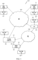
- the communication system can avoid duplicate email messages being transmitted to the two devices when in a charging arrangement and sharing a single user interface. This helps improve data throughput in the communication system and improves utilization of resources in the two devices.
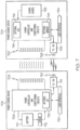
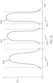
- the conditioning circuits 718 are electrically coupled with the transmit coil 720 in a tuned L-C circuit that facilitates transmitting, via inductive coupling, a charging energy signal at the pass band resonant frequency of the tuned L-C circuit.
- a variable frequency oscillator 719 is provided as part of the tuned L-C circuit such that the pass band resonant frequency can be adjusted by the power controller 718.
- the power controller and conditioning circuits 718 are electrically coupled to the power source 722 which is utilized by the power controller 718 to generate the charging energy signal that is inductively transmitted from the transmit coil 720 at the pass band resonant frequency of the tuned L-C circuit.
- a sensor 724 monitors the charging status of the power source 722 at the power source device 704. Additionally, the sensor 724 can provide an indication of level of a charge energy signal to the power controller 718. In this way, the power controller 718 can monitor the charge level of the power source 722, in this example the rechargeable battery 722.
- the controller 802 is coupled to one or more Input-Output data ports 822 that allowed data communication via the ports 822 with other devices.
- a variable frequency filter (VFF) 838 is included in the power conditioning circuits 830 and controlled by the controller 802 to adjust a pass band resonant frequency of a tuned L-C circuit that includes the receiver coil 828.
- VFF variable frequency filter
- the controller 802 can adjust the resonant frequency pass band of the receiver circuit that includes the receiver coil 828 for receiving charging energy signal at the tuned resonant frequency.
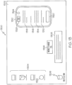
- a dialog box 1308 on the display screen 1302 can communicate to a user of the lap top 202 the messages that were received by the mobile phone 1 device 114.
- the user of the lap top device 202 can utilize a single user interface to receive (and optionally send) messages whether received by the mobile phone 1 device 114 or the lap top 202. That is, the mobile phone 1 device 114, when in a charging arrangement with the lap top 202, can communicate with the lap top 202 via the short range communication transceivers 714, 726, and thereby communicate message information between the devices 114, 202.
- a dialog box 1328 in the graphical representation 1310 of the mobile phone 1 device 114 on the display screen 1302 provides charged indication information of the current charge status of the re-chargeable battery 710 of the mobile phone 1 device 114.
- the dialog box 1328 shows that the re-chargeable battery 710 of the mobile phone 1 device 114 is at approximately 72% of total charge of the battery.
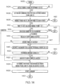
- the personal computer (PC) 112 determines the battery level of the Smartphone battery 710 by communication with the Smartphone 114, at step 1808.
- the PC 112, at step 1810 determines whether it is plugged into an AC outlet, at step 1810. If the PC 112 is plugged into an AC outlet, at step 1810, then the PC 112 charges the Smartphone 114 according to a maximum charging protocol to charge the battery of the Smartphone to 100% of capacity, at step 1816.
- the operational sequence then starts charging the Smartphone battery 710, at step 1822, and then the operational sequence exits, at step 1824.
- the present subject matter can be realized in hardware, software, or a combination of hardware and software.
- a computer system can be realized in a centralized fashion in one computer system, or in a distributed fashion where different elements are spread across several interconnected computer systems. Any kind of computer system - or other apparatus adapted for carrying out the methods described herein - is suitable.
- a typical combination of hardware and software could be a general purpose computer system with a computer program that, when being loaded and executed, controls the computer system such that it carries out the methods described herein.
Landscapes
- Engineering & Computer Science (AREA)
- Computer Networks & Wireless Communication (AREA)
- Power Engineering (AREA)
- Telephone Function (AREA)
- Mobile Radio Communication Systems (AREA)
- Charge And Discharge Circuits For Batteries Or The Like (AREA)
Claims (10)
- Eine Stromquellenvorrichtung (704, 905), die Folgendes beinhaltet:eine Stromquelle (722, 410);einen Nahbereichsdrahtloskommunikationsempfänger (728) zum drahtlosen Empfangen von Informationssignalen, die von mindestens einer Stromladungsvorrichtung (702, 800, 903) übertragen werden;eine drahtlose Stromübertragungsschaltung (720, 214), wobei die drahtlose Stromübertragungsschaltung einen Frequenzdurchlassbereich um eine Resonanzfrequenz herum aufweist und mit der Stromquelle elektrisch gekoppelt ist, um Ladungsenergie von der Stromquelle an die drahtlose Stromübertragungsschaltung zu koppeln und dadurch ein Ladungsenergiesignal, das eine Frequenz innerhalb des Frequenzdurchlassbereichs aufweist, drahtlos zu übertragen;einen Nahbereichsdrahtloskommunikationsüberträger (728) zum drahtlosen Übertragen von Informationssignalen an die mindestens eine Stromladungsvorrichtung (702, 800, 903); undeine Ladungsstromsteuereinheit (718, 404), die mit der drahtlosen Stromübertragungsschaltung, dem Nahbereichsdrahtloskommunikationsüberträger und dem Nahbereichsdrahtloskommunikationsempfänger kommunikativ gekoppelt ist, wobei der Ladungsstromsteuereinheit für Folgendes konfiguriert ist:Koppeln von Ladungsenergie von der Stromquelle (722, 410) an die drahtlose Stromübertragungsschaltung;dadurch gekennzeichnet, dass die Ladungsstromsteuereinheit ferner für Folgendes konfiguriert ist:drahtloses Empfangen, durch den Nahbereichsdrahtloskommunikationsempfänger, mindestens eines Informationssignals, das von der mindestens einen Stromladungsvorrichtung übertragen wird, wobei das mindestens eine Informationssignal ein Ladungsstandinformationssignal beinhaltet, das eine Angabe eines Niveaus eines Ladungsenergiesignals bereitstellt, das durch die mindestens eine Stromladungsvorrichtung von der Stromquellenvorrichtung drahtlos empfangen wird;Bestimmen, basierend auf der Angabe des Niveaus des Ladungsenergiesignals, das durch die mindestens eine Stromladungsvorrichtung von der Stromquellenvorrichtung drahtlos empfangen wird, ob sich die mindestens eine Stromladungsvorrichtung in einer Ladungsanordnung befindet, wobei sich die Stromquellenvorrichtung und die mindestens eine Stromladungsvorrichtung in der Ladungsanordnung befinden, wenn die Stromquellenvorrichtung fähig ist, ein Ladungssignal an die mindestens eine Stromladungsvorrichtung zu übertragen, um die mindestens eine Stromladungsvorrichtung zu laden;Steuern der drahtlosen Stromübertragungsschaltung, das Ladungsenergiesignal drahtlos zu übertragen;Bestimmen, basierend auf Informationen, die von einer Nachrichtensynchronisierungsdatenbank (110) abgerufen werden, die mit der Stromquellenvorrichtung und der mindestens einen Stromladungsvorrichtung operativ gekoppelt ist, dass die mindestens eine Stromladungsvorrichtung keine Nachricht von einem Drahtloskommunikationsnetzwerk (100) empfängt, wobei die Nachricht einer Nachricht entspricht, die von der Stromquellenvorrichtung empfangen wird; undals Antwort auf das Bestimmen, dass sich die mindestens eine Stromladungsvorrichtung in der Ladungsanordnung mit der Stromquellenvorrichtung befindet, drahtloses Übertragen, durch den Nahbereichsdrahtloskommunikationsüberträger, mindestens eines Informationssignals, das die Nachricht beinhaltet, die von der Stromquellenvorrichtung empfangen wird, an die mindestens eine Stromladungsvorrichtung.
- Stromquellenvorrichtung gemäß Anspruch 1, wobei die Ladungsstromsteuereinheit ferner für Folgendes konfiguriert ist:
drahtloses Übertragen mindestens eines Informationssignals von dem Nahbereichsdrahtloskommunikationsüberträger an die mindestens eine Stromladungsvorrichtung, das angibt, dass bestimmt wird, dass sich die mindestens eine Stromladungsvorrichtung in einer Ladungsanordnung mit der Stromquellenvorrichtung befindet. - Stromquellenvorrichtung gemäß einem der Ansprüche 1 oder 2, wobei die Ladungsstromsteuereinheit ferner für Folgendes konfiguriert ist:
drahtloses Empfangen, durch den Nahbereichsdrahtloskommunikationsempfänger, eines Ladungsstandinformationssignals von der mindestens einen Stromladungsvorrichtung, wobei das Ladungsstandinformationssignal eine Angabe eines Ladungsniveaus einer wiederaufladbaren Stromquelle in der mindestens einen Stromladungsvorrichtung bereitstellt. - Stromquellenvorrichtung gemäß einem der Ansprüche 1, 2 oder 3, wobei die Ladungsstromsteuereinheit ferner für Folgendes konfiguriert ist:
drahtloses Empfangen, durch den Nahbereichsdrahtloskommunikationsempfänger (728), eines Ladungsstandinformationssignals von der mindestens einen Stromladungsvorrichtung, wobei das Ladungsstandinformationssignal eine Angabe eines Ladungsstands einer wiederaufladbaren Stromquelle in der mindestens einen Stromladungsvorrichtung bereitstellt. - Stromquellenvorrichtung gemäß einem der Ansprüche 1, 2, 3 oder 4, wobei die Ladungsstromsteuereinheit (718, 404) ferner für Folgendes konfiguriert ist:
als Antwort auf das Bestimmen, dass sich die mindestens eine Stromladungsvorrichtung in einer Ladungsanordnung mit der Stromquellenvorrichtung befindet, drahtloses Empfangen, durch den Nahbereichsdrahtloskommunikationsempfänger, eines Informationssignals von der mindestens einen Stromladungsvorrichtung, wobei das Informationssignal eine Nachricht beinhaltet, die von der mindestens einen Stromladungsvorrichtung empfangen wird und davon an die Stromquellenvorrichtung weitergeleitet wird. - Stromquellenvorrichtung gemäß einem der Ansprüche 1 bis 5, wobei das mindestens eine Informationssignal, das von der mindestens einen Stromladungsvorrichtung übertragen wird, eine Nachricht beinhaltet, die durch die mindestens eine Stromladungsvorrichtung von einem Drahtloskommunikationssystem drahtlos empfangen wird und dadurch an die Stromquellenvorrichtung weitergeleitet wird; und wobei die Stromquellenvorrichtung ferner Folgendes beinhaltet:
eine Benutzerschnittstelle (734), die mit der Ladungsstromsteuereinheit (718, 404) kommunikativ gekoppelt ist, wobei die Ladungsstromsteuereinheit ferner für Folgendes konfiguriert ist:
Bereitstellen, für die Benutzerschnittstelle, der Nachricht, die durch die mindestens Stromquellenvorrichtung empfangen wird. - Stromquellenvorrichtung gemäß Anspruch 1, wobei die drahtlose Stromübertragungsschaltung eine induktive drahtlose Stromübertragungsschaltung ist, wobei die Stromquellenvorrichtung ferner Folgendes beinhaltet:eine Benutzerschnittstelle (734), die sperrbar ist, um Benutzerzugriff auf mindestens einen Abschnitt der Benutzerschnittstelle zu verhindern; undwobei die Ladungsstromsteuereinheit ferner für Folgendes konfiguriert ist:
Entsperren der Benutzerschnittstelle und Erlauben von Benutzerzugriff auf den mindestens einen Abschnitt der Benutzerschnittstelle basierend auf dem Empfangen von Informationen von der mindestens einen Stromladungsvorrichtung über den Nahbereichsdrahtloskommunikationsempfänger und Bestimmen, dass sich die Stromquellenvorrichtung und die mindestens eine Stromladungsvorrichtung in der Ladungsanordnung befinden. - Stromquellenvorrichtung gemäß Anspruch 7, wobei die Ladungsstromsteuereinheit ferner für Folgendes konfiguriert ist:
Entsperren der Benutzerschnittstelle und Erlauben von Benutzerzugriff auf den mindestens einen Abschnitt der Benutzerschnittstelle basierend auf dem Empfangen von Informationen von der mindestens einen Stromladungsvorrichtung über den Nahbereichsdrahtloskommunikationsempfänger, die angeben, dass die mindestens eine Stromladungsvorrichtung mindestens eines von Folgenden aufweist:eine gegenwärtig entsperrte Benutzerschnittstelle; undeine Benutzerschnittstelle, die schon mindestens einen vorbestimmten Zeitraum entsperrt ist. - Stromquellenvorrichtung gemäß einem der Ansprüche 7 oder 8, wobei die Ladungsstromsteuereinheit ferner für Folgendes konfiguriert ist:Entsperren der Benutzerschnittstelle und Erlauben von Benutzerzugriff auf den mindestens einen Abschnitt der Benutzerschnittstelle basierend auf dem Empfangen von Informationen von der mindestens einen Stromladungsvorrichtung über den Nahbereichsdrahtloskommunikationsempfänger, die angeben, dass die mindestens eine Stromladungsvorrichtung eine Benutzerschnittstelle aufweist, die schon mindestens einen vorbestimmten Zeitraum entsperrt ist, wobei die Ladungsstromsteuereinheit basierend auf dem Bestimmen, dass die mindestens eine Stromladungsvorrichtung eine Benutzerschnittstelle aufweist, die durch Empfang eines Passworts entsperrt wurde, einem Benutzer eingeschränkten Zugriff auf den mindestens einen Abschnitt der Benutzerschnittstelle erlaubt; undErlauben von vollem Zugriff auf den mindestens einen Abschnitt der Benutzerschnittstelle durch einen Benutzer basierend auf der Bestimmung, dass die mindestens eine Stromladungsvorrichtung eine Benutzerschnittstelle aufweist, die durch die Erfassung biometrischer Informationen eines Benutzers entsperrt wurde.
- Ein Verfahren an einer Stromquellenvorrichtung (704, 905), wobei die Stromquellenvorrichtung Folgendes beinhaltet:eine Stromquelle (722, 410);einen Nahbereichsdrahtloskommunikationsempfänger (728) zum drahtlosen Empfangen von Informationssignalen, die von mindestens einer Stromladungsvorrichtung (702, 800, 903) übertragen werden;eine drahtlose Stromübertragungsschaltung (720, 214), wobei die drahtlose Stromübertragungsschaltung einen Frequenzdurchlassbereich um eine Resonanzfrequenz herum aufweist und mit der Stromquelle elektrisch gekoppelt ist, um Ladungsenergie von der Stromquelle an die drahtlose Stromübertragungsschaltung zu koppeln und dadurch ein Ladungsenergiesignal, das die Frequenz innerhalb des Frequenzdurchlassbereichs aufweist, drahtlos zu übertragen;einen Nahbereichsdrahtloskommunikationsüberträger (728) zum drahtlosen Übertragen von Informationssignalen an die mindestens eine Stromladungsvorrichtung (702, 800, 903); undeine Ladungsstromsteuereinheit (718, 404), der mit der drahtlosen Stromübertragungsschaltung, dem Nahbereichsdrahtloskommunikationsüberträger und dem Nahbereichsdrahtloskommunikationsempfänger kommunikativ gekoppelt ist, wobei das Verfahren Folgendes beinhaltet:Koppeln von Ladungsenergie von der Stromquelle (722, 410) an die drahtlose Stromübertragungsschaltung;dadurch gekennzeichnet, dass das Verfahren ferner Folgendes beinhaltet:drahtloses Empfangen, durch den Nahbereichsdrahtloskommunikationsempfänger, mindestens eines Informationssignals, das von der mindestens einen Stromladungsvorrichtung übertragen wird, wobei das mindestens eine Informationssignal ein Ladungsstandinformationssignal beinhaltet, das eine Angabe eines Niveaus eines Ladungsenergiesignals bereitstellt, das durch die mindestens eine Stromladungsvorrichtung von der Stromquellenvorrichtung drahtlos empfangen wird;Bestimmen, basierend auf der Angabe des Niveaus des Ladungsenergiesignals, das durch die mindestens eine Stromladungsvorrichtung von der Stromquellenvorrichtung drahtlos empfangen wird, ob sich die mindestens eine Stromladungsvorrichtung in einer Ladungsanordnung befindet, wobei sich die Stromquellenvorrichtung und die mindestens eine Stromladungsvorrichtung in der Ladungsanordnung befinden, wenn die Stromquellenvorrichtung fähig ist, ein Ladungssignal an die mindestens eine Stromladungsvorrichtung zu übertragen, um die mindestens eine Stromladungsvorrichtung zu laden;Steuern der drahtlosen Stromübertragungsschaltung, das Ladungsenergiesignal drahtlos zu übertragen;Bestimmen, basierend auf Informationen, die von einer Nachrichtensynchronisierungsdatenbank (110) abgerufen werden, die mit der Stromquellenvorrichtung und der mindestens einen Stromladungsvorrichtung operativ gekoppelt ist, dass die mindestens eine Stromladungsvorrichtung keine Nachricht von einem Drahtloskommunikationsnetzwerk (100) empfängt, wobei die Nachricht einer Nachricht entspricht, die von der Stromquellenvorrichtung empfangen wird; undals Antwort auf das Bestimmen, dass sich die mindestens eine Stromladungsvorrichtung in der Ladungsanordnung mit der Stromquellenvorrichtung befindet, drahtloses Übertragen, durch den Nahbereichsdrahtloskommunikationsüberträger, der Nachricht, die von der Stromquellenvorrichtung empfangen wird, an die mindestens eine Stromladu ngsvorrichtung.
Priority Applications (4)
| Application Number | Priority Date | Filing Date | Title |
|---|---|---|---|
| EP23185815.0A EP4243156B1 (de) | 2011-10-05 | 2011-10-05 | Drahtloses laden und kommunizieren mit stromquellenvorrichtungen und stromladevorrichtungen in einem kommunikationssystem |
| ES11184012T ES2950409T3 (es) | 2011-10-05 | 2011-10-05 | Carga y comunicación inalámbrica con dispositivos de fuente de alimentación y dispositivos de carga de potencia en un sistema de comunicación |
| EP11184012.0A EP2579423B8 (de) | 2011-10-05 | 2011-10-05 | Drahtloses Aufladen und Kommunizieren mit Stromquellenvorrichtungen und Stromladungsvorrichtungen in einem Kommunikationssystem |
| CA2791980A CA2791980C (en) | 2011-10-05 | 2012-10-05 | Wireless charging and communication with power source devices and power charge devices in a communication system |
Applications Claiming Priority (1)
| Application Number | Priority Date | Filing Date | Title |
|---|---|---|---|
| EP11184012.0A EP2579423B8 (de) | 2011-10-05 | 2011-10-05 | Drahtloses Aufladen und Kommunizieren mit Stromquellenvorrichtungen und Stromladungsvorrichtungen in einem Kommunikationssystem |
Related Child Applications (2)
| Application Number | Title | Priority Date | Filing Date |
|---|---|---|---|
| EP23185815.0A Division-Into EP4243156B1 (de) | 2011-10-05 | 2011-10-05 | Drahtloses laden und kommunizieren mit stromquellenvorrichtungen und stromladevorrichtungen in einem kommunikationssystem |
| EP23185815.0A Division EP4243156B1 (de) | 2011-10-05 | 2011-10-05 | Drahtloses laden und kommunizieren mit stromquellenvorrichtungen und stromladevorrichtungen in einem kommunikationssystem |
Publications (5)
| Publication Number | Publication Date |
|---|---|
| EP2579423A1 EP2579423A1 (de) | 2013-04-10 |
| EP2579423A9 EP2579423A9 (de) | 2014-04-16 |
| EP2579423B1 true EP2579423B1 (de) | 2023-07-19 |
| EP2579423C0 EP2579423C0 (de) | 2023-07-19 |
| EP2579423B8 EP2579423B8 (de) | 2023-08-23 |
Family
ID=44720756
Family Applications (2)
| Application Number | Title | Priority Date | Filing Date |
|---|---|---|---|
| EP11184012.0A Active EP2579423B8 (de) | 2011-10-05 | 2011-10-05 | Drahtloses Aufladen und Kommunizieren mit Stromquellenvorrichtungen und Stromladungsvorrichtungen in einem Kommunikationssystem |
| EP23185815.0A Active EP4243156B1 (de) | 2011-10-05 | 2011-10-05 | Drahtloses laden und kommunizieren mit stromquellenvorrichtungen und stromladevorrichtungen in einem kommunikationssystem |
Family Applications After (1)
| Application Number | Title | Priority Date | Filing Date |
|---|---|---|---|
| EP23185815.0A Active EP4243156B1 (de) | 2011-10-05 | 2011-10-05 | Drahtloses laden und kommunizieren mit stromquellenvorrichtungen und stromladevorrichtungen in einem kommunikationssystem |
Country Status (3)
| Country | Link |
|---|---|
| EP (2) | EP2579423B8 (de) |
| CA (1) | CA2791980C (de) |
| ES (1) | ES2950409T3 (de) |
Families Citing this family (7)
| Publication number | Priority date | Publication date | Assignee | Title |
|---|---|---|---|---|
| US20180004298A1 (en) * | 2015-01-22 | 2018-01-04 | Texas Tech University System | System and method for non-contact interaction with mobile devices |
| CN106410303B (zh) * | 2015-07-27 | 2019-02-19 | 小米科技有限责任公司 | 充电方法及装置 |
| US10121295B2 (en) * | 2015-08-31 | 2018-11-06 | Huf North America Automotive Parts Manufacturing Corp. | System and method for accessing a vehicle |
| CN108781000B (zh) * | 2018-06-04 | 2022-03-11 | 深圳市奥星澳科技有限公司 | 共享充电方法、系统、移动终端、共享充电设备及服务器 |
| JP7200784B2 (ja) * | 2019-03-20 | 2023-01-10 | Tdk株式会社 | 送電装置およびワイヤレス電力伝送システム |
| CN116800570A (zh) * | 2022-03-15 | 2023-09-22 | 北京小米移动软件有限公司 | 信号传输方法、信号传输装置及存储介质 |
| CN115473355B (zh) * | 2022-07-21 | 2024-11-22 | 北京罗克维尔斯科技有限公司 | 无线充电的检测方法及装置、车辆、电子设备和存储介质 |
Family Cites Families (11)
| Publication number | Priority date | Publication date | Assignee | Title |
|---|---|---|---|---|
| US7518267B2 (en) * | 2003-02-04 | 2009-04-14 | Access Business Group International Llc | Power adapter for a remote device |
| JP2006229583A (ja) * | 2005-02-17 | 2006-08-31 | Eastman Kodak Co | 通信システム及びデジタルカメラ並びにドック装置 |
| KR100736053B1 (ko) * | 2005-10-24 | 2007-07-06 | 삼성전자주식회사 | 유도 방식에 의해 무선으로 전원을 공유하는 장치 및 방법 |
| DE102005056862A1 (de) * | 2005-11-29 | 2007-06-06 | Siemens Ag | Mobile Chipkarteneinrichtung und Verfahren zur Authentifizierung mittels Chipkarte gegenüber mindestens einer Einrichtung |
| KR20070099245A (ko) * | 2006-04-04 | 2007-10-09 | 엘지전자 주식회사 | 정보 처리 장치의 충전장치 |
| US20100277121A1 (en) * | 2008-09-27 | 2010-11-04 | Hall Katherine L | Wireless energy transfer between a source and a vehicle |
| US20100225270A1 (en) * | 2009-03-08 | 2010-09-09 | Qualcomm Incorporated | Wireless power transfer for chargeable devices |
| JP2011029799A (ja) * | 2009-07-23 | 2011-02-10 | Sony Corp | 非接触給電通信装置、非接触受電通信装置、給電通信制御方法および受電通信制御方法 |
| US8390249B2 (en) * | 2009-11-30 | 2013-03-05 | Broadcom Corporation | Battery with integrated wireless power receiver and/or RFID |
| US9590444B2 (en) * | 2009-11-30 | 2017-03-07 | Broadcom Corporation | Device with integrated wireless power receiver configured to make a charging determination based on a level of battery life and charging efficiency |
| TWM389866U (en) * | 2010-03-30 | 2010-10-01 | Winharbor Technology Co Ltd | Notebook with wireless charging |
-
2011
- 2011-10-05 EP EP11184012.0A patent/EP2579423B8/de active Active
- 2011-10-05 EP EP23185815.0A patent/EP4243156B1/de active Active
- 2011-10-05 ES ES11184012T patent/ES2950409T3/es active Active
-
2012
- 2012-10-05 CA CA2791980A patent/CA2791980C/en active Active
Also Published As
| Publication number | Publication date |
|---|---|
| EP2579423A9 (de) | 2014-04-16 |
| EP2579423A1 (de) | 2013-04-10 |
| EP2579423B8 (de) | 2023-08-23 |
| EP4243156C0 (de) | 2024-08-07 |
| ES2950409T3 (es) | 2023-10-09 |
| EP4243156B1 (de) | 2024-08-07 |
| CA2791980A1 (en) | 2013-04-05 |
| EP4243156A2 (de) | 2023-09-13 |
| CA2791980C (en) | 2016-06-14 |
| EP4243156A3 (de) | 2023-11-08 |
| EP2579423C0 (de) | 2023-07-19 |
Similar Documents
| Publication | Publication Date | Title |
|---|---|---|
| US9419444B2 (en) | Wireless charging and communication with power source devices and power charge devices in a communication system | |
| US9319855B2 (en) | Wireless charging and communication with wireless communication devices in a communication system | |
| EP2579522B1 (de) | Drahtloses Stromversorgung Aufladen und Kommunizieren mit drahtlosen Kommunikationsvorrichtungen in einem Kommunikationssystem | |
| EP2579423B1 (de) | Drahtloses Aufladen und Kommunizieren mit Stromquellenvorrichtungen und Stromladungsvorrichtungen in einem Kommunikationssystem | |
| US9742216B2 (en) | Wireless charging system for variable charging mode | |
| US9300146B2 (en) | Power supply device, communication terminal device, and non-contact power transmission method | |
| US9948133B2 (en) | Wireless charging method, wireless charging device, and wireless charging system | |
| CN104428972A (zh) | 用于小型设备无线充电模式的系统、方法和装置 | |
| KR20110103295A (ko) | 통신망을 이용한 무선 충전 방법 | |
| JP6185396B2 (ja) | ウエアラブル型の小形電気機器 | |
| KR20180137773A (ko) | 사용자 단말에 탈부착되는 무선 충전 지원 액세서리 및 이에 기반한 무선 충전 시스템 | |
| CN112886994A (zh) | 一种终端 | |
| JP7854080B2 (ja) | オーディオビジュアル電子デバイスと共に動作可能な無線電力システム | |
| JP2022191011A (ja) | 電子機器及びその制御方法、通信システム、プログラム |
Legal Events
| Date | Code | Title | Description |
|---|---|---|---|
| PUAI | Public reference made under article 153(3) epc to a published international application that has entered the european phase |
Free format text: ORIGINAL CODE: 0009012 |
|
| 17P | Request for examination filed |
Effective date: 20111005 |
|
| AK | Designated contracting states |
Kind code of ref document: A1 Designated state(s): AL AT BE BG CH CY CZ DE DK EE ES FI FR GB GR HR HU IE IS IT LI LT LU LV MC MK MT NL NO PL PT RO RS SE SI SK SM TR |
|
| AX | Request for extension of the european patent |
Extension state: BA ME |
|
| RAP1 | Party data changed (applicant data changed or rights of an application transferred) |
Owner name: BLACKBERRY LIMITED |
|
| RAP1 | Party data changed (applicant data changed or rights of an application transferred) |
Owner name: BLACKBERRY LIMITED |
|
| STAA | Information on the status of an ep patent application or granted ep patent |
Free format text: STATUS: EXAMINATION IS IN PROGRESS |
|
| 17Q | First examination report despatched |
Effective date: 20200221 |
|
| GRAP | Despatch of communication of intention to grant a patent |
Free format text: ORIGINAL CODE: EPIDOSNIGR1 |
|
| STAA | Information on the status of an ep patent application or granted ep patent |
Free format text: STATUS: GRANT OF PATENT IS INTENDED |
|
| INTG | Intention to grant announced |
Effective date: 20230303 |
|
| GRAS | Grant fee paid |
Free format text: ORIGINAL CODE: EPIDOSNIGR3 |
|
| GRAA | (expected) grant |
Free format text: ORIGINAL CODE: 0009210 |
|
| STAA | Information on the status of an ep patent application or granted ep patent |
Free format text: STATUS: THE PATENT HAS BEEN GRANTED |
|
| AK | Designated contracting states |
Kind code of ref document: B1 Designated state(s): AL AT BE BG CH CY CZ DE DK EE ES FI FR GB GR HR HU IE IS IT LI LT LU LV MC MK MT NL NO PL PT RO RS SE SI SK SM TR |
|
| REG | Reference to a national code |
Ref country code: GB Ref legal event code: FG4D |
|
| REG | Reference to a national code |
Ref country code: CH Ref legal event code: PK Free format text: BERICHTIGUNG B8 Ref country code: CH Ref legal event code: EP |
|
| REG | Reference to a national code |
Ref country code: DE Ref legal event code: R096 Ref document number: 602011074078 Country of ref document: DE |
|
| RAP2 | Party data changed (patent owner data changed or rights of a patent transferred) |
Owner name: MALIKIE INNOVATIONS LIMITED |
|
| REG | Reference to a national code |
Ref country code: IE Ref legal event code: FG4D |
|
| U01 | Request for unitary effect filed |
Effective date: 20230725 |
|
| U07 | Unitary effect registered |
Designated state(s): AT BE BG DE DK EE FI FR IT LT LU LV MT NL PT SE SI Effective date: 20230731 |
|
| REG | Reference to a national code |
Ref country code: ES Ref legal event code: FG2A Ref document number: 2950409 Country of ref document: ES Kind code of ref document: T3 Effective date: 20231009 |
|
| REG | Reference to a national code |
Ref country code: LT Ref legal event code: MG9D |
|
| U20 | Renewal fee for the european patent with unitary effect paid |
Year of fee payment: 13 Effective date: 20231027 |
|
| PG25 | Lapsed in a contracting state [announced via postgrant information from national office to epo] |
Ref country code: GR Free format text: LAPSE BECAUSE OF FAILURE TO SUBMIT A TRANSLATION OF THE DESCRIPTION OR TO PAY THE FEE WITHIN THE PRESCRIBED TIME-LIMIT Effective date: 20231020 |
|
| PG25 | Lapsed in a contracting state [announced via postgrant information from national office to epo] |
Ref country code: IS Free format text: LAPSE BECAUSE OF FAILURE TO SUBMIT A TRANSLATION OF THE DESCRIPTION OR TO PAY THE FEE WITHIN THE PRESCRIBED TIME-LIMIT Effective date: 20231119 |
|
| PG25 | Lapsed in a contracting state [announced via postgrant information from national office to epo] |
Ref country code: RS Free format text: LAPSE BECAUSE OF FAILURE TO SUBMIT A TRANSLATION OF THE DESCRIPTION OR TO PAY THE FEE WITHIN THE PRESCRIBED TIME-LIMIT Effective date: 20230719 Ref country code: NO Free format text: LAPSE BECAUSE OF FAILURE TO SUBMIT A TRANSLATION OF THE DESCRIPTION OR TO PAY THE FEE WITHIN THE PRESCRIBED TIME-LIMIT Effective date: 20231019 Ref country code: IS Free format text: LAPSE BECAUSE OF FAILURE TO SUBMIT A TRANSLATION OF THE DESCRIPTION OR TO PAY THE FEE WITHIN THE PRESCRIBED TIME-LIMIT Effective date: 20231119 Ref country code: HR Free format text: LAPSE BECAUSE OF FAILURE TO SUBMIT A TRANSLATION OF THE DESCRIPTION OR TO PAY THE FEE WITHIN THE PRESCRIBED TIME-LIMIT Effective date: 20230719 Ref country code: GR Free format text: LAPSE BECAUSE OF FAILURE TO SUBMIT A TRANSLATION OF THE DESCRIPTION OR TO PAY THE FEE WITHIN THE PRESCRIBED TIME-LIMIT Effective date: 20231020 |
|
| PG25 | Lapsed in a contracting state [announced via postgrant information from national office to epo] |
Ref country code: PL Free format text: LAPSE BECAUSE OF FAILURE TO SUBMIT A TRANSLATION OF THE DESCRIPTION OR TO PAY THE FEE WITHIN THE PRESCRIBED TIME-LIMIT Effective date: 20230719 |
|
| REG | Reference to a national code |
Ref country code: DE Ref legal event code: R097 Ref document number: 602011074078 Country of ref document: DE |
|
| PG25 | Lapsed in a contracting state [announced via postgrant information from national office to epo] |
Ref country code: SM Free format text: LAPSE BECAUSE OF FAILURE TO SUBMIT A TRANSLATION OF THE DESCRIPTION OR TO PAY THE FEE WITHIN THE PRESCRIBED TIME-LIMIT Effective date: 20230719 Ref country code: RO Free format text: LAPSE BECAUSE OF FAILURE TO SUBMIT A TRANSLATION OF THE DESCRIPTION OR TO PAY THE FEE WITHIN THE PRESCRIBED TIME-LIMIT Effective date: 20230719 Ref country code: CZ Free format text: LAPSE BECAUSE OF FAILURE TO SUBMIT A TRANSLATION OF THE DESCRIPTION OR TO PAY THE FEE WITHIN THE PRESCRIBED TIME-LIMIT Effective date: 20230719 Ref country code: SK Free format text: LAPSE BECAUSE OF FAILURE TO SUBMIT A TRANSLATION OF THE DESCRIPTION OR TO PAY THE FEE WITHIN THE PRESCRIBED TIME-LIMIT Effective date: 20230719 |
|
| PLBE | No opposition filed within time limit |
Free format text: ORIGINAL CODE: 0009261 |
|
| STAA | Information on the status of an ep patent application or granted ep patent |
Free format text: STATUS: NO OPPOSITION FILED WITHIN TIME LIMIT |
|
| PG25 | Lapsed in a contracting state [announced via postgrant information from national office to epo] |
Ref country code: MC Free format text: LAPSE BECAUSE OF FAILURE TO SUBMIT A TRANSLATION OF THE DESCRIPTION OR TO PAY THE FEE WITHIN THE PRESCRIBED TIME-LIMIT Effective date: 20230719 |
|
| REG | Reference to a national code |
Ref country code: CH Ref legal event code: PL |
|
| 26N | No opposition filed |
Effective date: 20240422 |
|
| PG25 | Lapsed in a contracting state [announced via postgrant information from national office to epo] |
Ref country code: CH Free format text: LAPSE BECAUSE OF NON-PAYMENT OF DUE FEES Effective date: 20231031 |
|
| PG25 | Lapsed in a contracting state [announced via postgrant information from national office to epo] |
Ref country code: CH Free format text: LAPSE BECAUSE OF NON-PAYMENT OF DUE FEES Effective date: 20231031 |
|
| PG25 | Lapsed in a contracting state [announced via postgrant information from national office to epo] |
Ref country code: IE Free format text: LAPSE BECAUSE OF NON-PAYMENT OF DUE FEES Effective date: 20231005 |
|
| PG25 | Lapsed in a contracting state [announced via postgrant information from national office to epo] |
Ref country code: IE Free format text: LAPSE BECAUSE OF NON-PAYMENT OF DUE FEES Effective date: 20231005 |
|
| U20 | Renewal fee for the european patent with unitary effect paid |
Year of fee payment: 14 Effective date: 20241025 |
|
| PG25 | Lapsed in a contracting state [announced via postgrant information from national office to epo] |
Ref country code: CY Free format text: LAPSE BECAUSE OF FAILURE TO SUBMIT A TRANSLATION OF THE DESCRIPTION OR TO PAY THE FEE WITHIN THE PRESCRIBED TIME-LIMIT; INVALID AB INITIO Effective date: 20111005 |
|
| PG25 | Lapsed in a contracting state [announced via postgrant information from national office to epo] |
Ref country code: HU Free format text: LAPSE BECAUSE OF FAILURE TO SUBMIT A TRANSLATION OF THE DESCRIPTION OR TO PAY THE FEE WITHIN THE PRESCRIBED TIME-LIMIT; INVALID AB INITIO Effective date: 20111005 |
|
| U20 | Renewal fee for the european patent with unitary effect paid |
Year of fee payment: 15 Effective date: 20251027 |
|
| PG25 | Lapsed in a contracting state [announced via postgrant information from national office to epo] |
Ref country code: TR Free format text: LAPSE BECAUSE OF FAILURE TO SUBMIT A TRANSLATION OF THE DESCRIPTION OR TO PAY THE FEE WITHIN THE PRESCRIBED TIME-LIMIT Effective date: 20230719 |
|
| PGFP | Annual fee paid to national office [announced via postgrant information from national office to epo] |
Ref country code: GB Payment date: 20251023 Year of fee payment: 15 |
|
| PGFP | Annual fee paid to national office [announced via postgrant information from national office to epo] |
Ref country code: ES Payment date: 20251118 Year of fee payment: 15 |