EP2579406A2 - Wire harness installation structure and wire harness-flattening band - Google Patents
Wire harness installation structure and wire harness-flattening band Download PDFInfo
- Publication number
- EP2579406A2 EP2579406A2 EP12008016.3A EP12008016A EP2579406A2 EP 2579406 A2 EP2579406 A2 EP 2579406A2 EP 12008016 A EP12008016 A EP 12008016A EP 2579406 A2 EP2579406 A2 EP 2579406A2
- Authority
- EP
- European Patent Office
- Prior art keywords
- wire harness
- fixing portion
- band
- linear member
- flattening
- Prior art date
- Legal status (The legal status is an assumption and is not a legal conclusion. Google has not performed a legal analysis and makes no representation as to the accuracy of the status listed.)
- Withdrawn
Links
Images


Classifications
-
- H—ELECTRICITY
- H02—GENERATION; CONVERSION OR DISTRIBUTION OF ELECTRIC POWER
- H02G—INSTALLATION OF ELECTRIC CABLES OR LINES, OR OF COMBINED OPTICAL AND ELECTRIC CABLES OR LINES
- H02G3/00—Installations of electric cables or lines or protective tubing therefor in or on buildings, equivalent structures or vehicles
- H02G3/02—Details
- H02G3/04—Protective tubing or conduits, e.g. cable ladders or cable troughs
- H02G3/0462—Tubings, i.e. having a closed section
- H02G3/0487—Tubings, i.e. having a closed section with a non-circular cross-section
-
- B—PERFORMING OPERATIONS; TRANSPORTING
- B60—VEHICLES IN GENERAL
- B60R—VEHICLES, VEHICLE FITTINGS, OR VEHICLE PARTS, NOT OTHERWISE PROVIDED FOR
- B60R16/00—Electric or fluid circuits specially adapted for vehicles and not otherwise provided for; Arrangement of elements of electric or fluid circuits specially adapted for vehicles and not otherwise provided for
- B60R16/02—Electric or fluid circuits specially adapted for vehicles and not otherwise provided for; Arrangement of elements of electric or fluid circuits specially adapted for vehicles and not otherwise provided for electric constitutive elements
- B60R16/0207—Wire harnesses
- B60R16/0215—Protecting, fastening and routing means therefor
-
- H—ELECTRICITY
- H02—GENERATION; CONVERSION OR DISTRIBUTION OF ELECTRIC POWER
- H02G—INSTALLATION OF ELECTRIC CABLES OR LINES, OR OF COMBINED OPTICAL AND ELECTRIC CABLES OR LINES
- H02G3/00—Installations of electric cables or lines or protective tubing therefor in or on buildings, equivalent structures or vehicles
- H02G3/30—Installations of cables or lines on walls, floors or ceilings
Landscapes
- Engineering & Computer Science (AREA)
- Architecture (AREA)
- Civil Engineering (AREA)
- Structural Engineering (AREA)
- Mechanical Engineering (AREA)
- Installation Of Indoor Wiring (AREA)
- Details Of Indoor Wiring (AREA)
Abstract
Description
- The present invention relates to a wire harness installation structure and a wire harness-flattening band, and particularly relates to improvements for enhancing the efficiency of an installing operation and also for making an installation region space-saving.
- Among vehicle seats, there are ones which are provided with an electrically-operated seat device for adjusting the position of a seat cushion in a forward-rearward direction and an upward-downward direction in accordance with the posture of a passenger and for making a reclining movement of a seat back and also with an air bag unit device for expanding an air bag between the passenger and a side door. A wire harness for supplying electric power to electrically-operated parts is installed in the vehicle seat on which such devices are mounted.
-
Fig. 22 andFig. 23 show a conventional example of a wire harness installation structure in a vehicle seat. As shown inFig. 22 andFig. 23 , the wireharness installation structure 1100 is such that within thevehicle seat 1106 in which aseat back 1104 is reclinably mounted on side frames 1102 (to which a seat cushion (not shown) is attached) through ahorizontal pivot shaft 1105, awire harness 1108 is installed on theseat back 1104 from the lower side of the seat. - The
wire harness 1108 is covered with and protected by acorrugated tube 1109 on an installation path. Anintermediate portion 1109a of thewire harness 1108 is installed along thepivot shaft 1105 in parallel relation thereto, and thisintermediate portion 1109a is fixed to thepivot shaft 1105 by aclamp 1110, and those portions continuous respectively with both sides of theintermediate portion 1109a are fixed respectively to the seat cushion and the seat back 1104 byrespective clamps - A wire harness installation structure of this kind is disclosed also in Patent Literature 1 mentioned below.
- Another wire harness installation structure is disclosed in
Patent Literature 2 mentioned below. The construction described inPatent Literature 2 will be explained below.
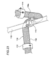
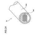
A wire harness W/H to be installed within a vehicle includes a portion Sa covered with atubular portion 1030 of a grommet as shown inFig. 24 , and a portion Sb covered with abellows portion 1031 as shown inFig. 25 . - The portion Sa covered with the
tubular portion 1030 was deformed into a flat shape, using aprotector 1035 as shown inFig. 25 , and was fixed to a vehicle panel or the like. By thus flattening the wire harness W/H, the wire harness W/H can be installed even in a narrow space. - The
protector 1035 is constructed such that abody portion 1036 and alid portion 1037 are interconnected through athin hinge 1038, and a retaining claw (not shown) formed at one end of thelid portion 1037 is retained on an end portion of alower portion 1036a of thebody portion 1036. Further, aclip 1039 for fixing theprotector 1035 to the vehicle panel or the like is provided at the lower side of the lower portion 1021a. - For flattening the wire harness W/H, the
lid portion 1037 is pivotally moved about thehinge 1038 in a clockwise direction (inFig. 25 ), thereby opening one side face of thebody portion 1036. Then, the wire harness W/H is inserted into thebody portion 1036, and thelid portion 1037 is closed, thereby flattening the wire harness W/H and also integrating the wire harness with theprotector 1035 as shown inFig. 25 . -
- Patent Literature 1:
JP-A-2006-304538 - Patent Literature 2:
JP-A-2004-236447 - However, with the improvement of the function of vehicle seats, the number of electrically-operated parts has increased, and with respect to wire harnesses used for supplying electric power to the electrically-operated parts, the number of wires bundled together has increased, so that there is a tendency for the bundle to become larger in diameter. With the construction described in Patent Literature 1 and so on, it is difficult to bend a wire harness of such a thick bundle so that it can be received in the inside of the vehicle sheet which is a narrow space, and there is a problem that the efficiency of the operation is bad.
- Furthermore, since it is difficult to bend the wire harness of a thick bundle, the radius of bending of the wire harness becomes large, so that there is a problem that a large installation space is needed.
- Furthermore, in the wire harness installation structure described in the
above Patent Literature 2, theprotector 1035 is need for flattening the wire harness W/H. Therefore, a space for theprotector 1035 is required at a position where the wire harness W/H is to be flattened. Therefore, when there was no space for accommodating theprotector 1035, it was difficult to install the wire harness W/H in a flattened condition. - Furthermore, protectors of various kinds are need according to the length, thickness, etc., of wire harnesses W/H, and therefore there is a problem that molds of various kinds for the production of the protectors must be prepared.
- A first object of the present invention is to solve the above problems, and is to provide a wire harness installation structure which can enhance the efficiency of a wire harness installing operation, and also can make an installation region space-saving.
- A second object of the present invention has been achieved in view of the above problems, and is to provide a wire harness-flattening band so constructed as to enable a wire harness to be easily installed in such a manner that a desired portion thereof is flattened without using any special member such as a protector, and also to be able to restrain displacement of the wire harness.
- The first object of the present invention is achieved by the following construction.
(1) A wire harness installation structure in which a wire harness formed by bundling a plurality of wires into a generally-circular form in a cross-sectional view is installed,
wherein the wire harness has a flat portion which is formed by thinning and flattening a part of a bundle of the plurality of wires over a predetermined length along an extending direction of the wire harness and are kept in a flat shape. - (2) A wire harness installation structure as set forth in the above (1), wherein the bundle of the plurality of wires is covered by a protective member made by resin along the extending direction, and are kept, together with the protective member, in the flat shape.
- (3) A wire harness installation structure as set forth in the above (1) or (2), wherein the bundle of the plurality of wires is kept in the flat shape by a binding member.
- (4) A wire harness installation structure as set forth in the above (1) or (2), wherein the bundle of the plurality of wires is received in a protector which includes a receiving space having a flat shape in the cross sectional view for receiving the bundle of the plurality of wires, so that the bundle of the plurality of wires is kept in the flat shape.
- (5) A wire harness installation structure as set forth in any one of the above (1) to (4), wherein an installing direction of the wire harness is changed by bending the flat portion.
- The second object is achieved by the following construction.
(6) A wire harness-flattening band for partially flattening a linear member including a wire bundle of a wire harness, comprising: - a wire harness fixing portion; and
- a binding member that fastens an outer periphery of the linear member in a direction intersecting a longitudinal direction of the linear member, and fixes the linear member to a surface of the wire harness fixing portion,
- wherein a portion of the linear member disposed on the surface of the wire harness fixing portion is pressed against the wire harness fixing portion by a fastening action of the binding member without interposing the binding member between the portion of the linear member and the surface of the wire harness fixing portion so that the portion of the linear member is flattened.
- (7) A wire harness-flattening band as set forth in the above (6), wherein the wire harness fixing portion has a plate portion on which the surface is formed, and a surface shape of the plate portion is flat, and the linear member is pressed against the surface by the binding member.
- (8) A wire harness-flattening band as set forth in the above (6), wherein the surface of the wire harness fixing portion has a slanting surface so that the flattened portion of the linear member is formed so as to be slant in a direction intersecting the longitudinal direction of the linear member.
- (9) A wire harness-flattening band as set forth in the above (6), wherein a protruded portion for bending the flattened portion of the linear member into an arcuate shape in a direction intersecting the longitudinal direction of the linear member is provided on the surface of the wire harness fixing portion.
- (10) A wire harness-flattening band as set forth in the above (6), wherein a plurality of protruded portions for bending the flattened portion of the linear member into an arcuate shape in a direction intersecting the longitudinal direction of the linear member are provided on the surface of the wire harness fixing portion, and are spaced a predetermined distance from each other in the longitudinal direction.
- (11) A wire harness-flattening band as set forth in any one of the above (6) to (10), wherein a plurality of retaining projections are provided on the surface of the wire harness fixing portion.
- (12) A wire harness-flattening band as set forth in any one of the above (6) to (11), wherein the binding member is a binding band passed through a through hole of the wire harness fixing portion which extends in a direction intersecting the longitudinal direction of the linear member.
- (13) A wire harness-flattening band as set forth in any one of the above (6) to (12), further comprising a retaining member that is formed integrally with the wire harness fixing portion so as to mount the wire harness fixing portion on the mating mounting member.
- In the construction of the above (1), even when the wire bundle forming the wire harness is thick, the wire harness can be easily bent at the flat portion formed by thinning and flattening a part thereof, and therefore the efficiency of the installing operation can be enhanced.
- Furthermore, since the wire harness can be easily bent at the flat portion, the bend radius will not become large, and the installation region can be made space-saving.
- Furthermore, since the wire harness can be easily bent at the flat portion, a large space is not required for changing the installing direction, and the installation region can be made space-saving.
- In the construction of the above (2), the wire harness is covered by the protective member, and therefore even when the wire harness is installed in a narrow space, the wire harness will not be brought into contact with a surrounding member by vibration and so on, and damage of the wire harness can be prevented.
- In the construction of the above (3), the flat shape can be maintained by the binding member, and therefore an arbitrary portion of the wire harness can be easily formed into a flat shape. Therefore, the flat portion can be formed at the installation site, and also a portion which is to be formed into a flat shape can be easily changed according to a change of an installation portion. Here, a tape, a tie band or the like can be used as the binding member.
- In the construction of the above (4), the flat shape is maintained by the protector, and therefore even when the wire harness is installed in a narrow space, the wire harness will not be brought into contact with a surrounding member by vibration and so on, and damage of the wire harness can be prevented.
- In the construction of the above (5), by changing the installing direction by bending the flat portion, the degree of freedom of installation of the wire harness is enhanced.
- In the wire harness-flattening band of the above (6), the linear member of the wire harness is fastened and fixed to the wire harness fixing portion by the fastening action of the binding member without interposing the binding member between the linear member and the surface of the wire harness fixing portion, and by doing so, a desired portion of the wire harness can be flattened in conformity with the surface shape of the fixing portion, and also displacement of the wire harness can be restrained.
- Incidentally, the flattened condition in the present invention includes, of course, a flat condition and also includes a curved condition. Namely, the flattened condition in the present invention means a condition in which the wire harness of a circular shape in a cross-sectional view is crushed, so that its cross-sectional shape becomes flattened, and the flattened cross-sectional shape may be flat or may be curved.
- In the constructions of the above (7), (8) and (9), by fixing the linear member of the wire harness along the surface of the wire harness fixing portion, the linear member can be flattened in a flat condition, a slanting condition or a mountain-shaped condition, and besides since the linear member is fixed by the binding member, displacement thereof can be restrained in both the installing direction and the direction perpendicularly intersecting this installing direction. Particularly by forming them into the slanting condition or the mountain-shaped condition, the fastening effect achieved at the time of the binding operation can be enhanced.
- In the construction of the above (10), the plurality of protruded portions are provided on the surface of the wire harness fixing portion, and are spaced the predetermined distance from each other in the installing direction, and therefore the linear member of the wire harness is flattened in conformity with the mountain-shape, and also is fastened at a position between the plurality of protruded portions by the binding member, so that the wire harness is flexibly deformed at this fastened portion, and the restraining of displacement of the wire harness is enhanced.
- In the construction of the above (11), the projections are provided on the surface of the wire harness fixing portion, and therefore at the time when the linear members of the wire harness are fixed to the wire harness fixing portion, the projections bite into the wire harness to retain the wire harness, and can positively prevent the displacement of the wire harness.
- In the construction of the above (12), the existing binding band can be used as the binding member, and therefore it is not necessary to newly produce a binding member for exclusive use.
- In the construction of the above (13), the wire harness fixing portion to which the linear members of the wire harness are fixed is mounted on the mating mounting member by the retaining member, and by doing so, the wire harness can be easily installed in a flat condition.
-
- [
Fig. 1] Fig. 1 is a perspective view of a wire harness used in a first embodiment of the present invention. - [
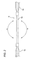
Fig. 2] Fig. 2 is a side-elevational view of the wire harness ofFig. 1 . - [
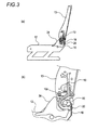
Fig. 3] Fig. 3 is views showing the installation of the wire harness of the first embodiment, andFig. 3 (a) is the view showing the installation in a reclining seat, andFig. 3 (b) is an enlarged view of an important portion ofFig. 3 (a) . - [
Fig. 4] Fig. 4 is a perspective view of a wire harness used in a second embodiment of the present invention. - [
Fig. 5] Fig. 5 is a perspective view of a modified wire harness used in the second embodiment of the present invention. - [
Fig. 6] Fig. 6 is partly-broken perspective view of a protector used in a third embodiment of the present invention. - [
Fig. 7] Fig. 7 is a perspective view showing the construction of a wire harness-flattening band representing a fourth embodiment of the present invention. - [
Fig. 8] Fig. 8 is a perspective view showing a flattened condition of a wire harness. - [
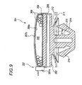
Fig. 9] Fig. 9 is a cross-sectional view showing the flattened condition of the wire harness. - [
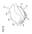
Fig. 10] Fig. 10 is a perspective view showing the construction of a wire harness-flattening band representing a fifth embodiment of the present invention. - [
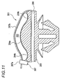
Fig. 11] Fig. 11 is a cross-sectional view showing a flattened condition of a wire harness. - [
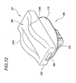
Fig. 12] Fig. 12 is a perspective view showing the construction of a wire harness-flattening band representing a sixth embodiment of the present invention. - [
Fig. 13] Fig. 13 is a cross-sectional view showing a flattened condition of a wire harness. - [
Fig. 14] Fig. 14 is a cross-sectional view showing a flexibly-deformed condition of the wire harness. - [
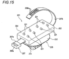
Fig. 15] Fig. 15 is a perspective view showing a wire harness-flattening band representing a seventh embodiment of the present invention. - [
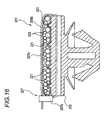
Fig. 16] Fig. 16 is a cross-sectional view showing a flattened condition of a wire harness. - [
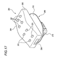
Fig. 17] Fig. 17 is a perspective view showing a wire harness-flattening band representing an eighth embodiment of the present invention. - [
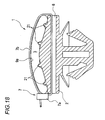
Fig. 18] Fig. 18 is a cross-sectional view showing a flattened condition of a wire harness. - [
Fig. 19] Fig. 19 is a perspective view showing a wire harness-flattening band representing a ninth embodiment of the present invention. - [
Fig. 20] Fig. 20 is a cross-sectional view showing a flattened condition of a wire harness. - [
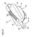
Fig. 21] Fig. 21 is a perspective view showing a modified example of a binding band. - [
Fig. 22] Fig. 22 is a view showing the installation of a conventional wire harness. - [
Fig. 23] Fig. 23 is an enlarged view of an important portion ofFig. 22 . - [
Fig. 24] Fig. 24 is a perspective view showing the shape of the conventional wire harness. - [
Fig. 25] Fig. 25 is a perspective view showing one example of a conventional wire harness installation structure. - Preferred embodiments of wire harness installation structures of the present invention in a vehicle seat will be described below in detail with reference to the drawings.
-
Fig. 1 is a perspective view of a wire harness representing a first embodiment of the invention,Fig. 2 is a side-elevational view of the wire harness ofFig. 1 , andFig. 3 is views showing the installation of the wire harness ofFig. 1 , andFig. 3(a) is the view showing the installation in a reclining seat, andFig. 3 (b) is an enlarged view of an important portion ofFig. 3 (a) . - The
wire harness 10 is formed by a plurality ofwires 42 bundled together, and suitable portions of thewire harness 10 spaced from each other in its extending direction are fixed by bindingmembers 44 such as a tape, a tie band or the like. Although thewire harness 10 originally has a generally-circular shape in cross-sectional view over an entire length thereof, aflat portion 10a formed by spreading the bundledwires 42 into a flat condition to thereby thin and flatten the wire harness is provided at a predetermined portion of the wire harness in the extending direction. Theflat portion 10a is kept in a flat shape by the bindingmembers 44 such as a tape, a tie band or the like. - The binding
members 44 bind theflat portion 10a at the suitable portions including both end portions of theflat portion 10a, and maintain the flat shape of thewire harness 10. - As a result of spreading of the
wires 42 into the flat condition, theflat portion 10a is made wider than a cross-sectionally generally-circular portion 10c as shown inFig. 1 , and is made thinner than the cross-sectionally genenerally-circular portion 10c as shown inFig. 2 . Therefore, theflat portion 10a can be easily bent in directions indicated by arrows A and B inFig. 2 . -
Figs. 3(a) and 3(b) show the condition in which the wire harness is installed around a pivot shaft of the reclining seat of the vehicle seats. A connector (not shown) is connected to a supply-side end portion of thewire harness 10 which is led out to the exterior of the seat, and this connector is connector-connected to another wire harness in a passenger compartment. That portion of thewire harness 10 disposed within the seat is branched off into a plurality of branch harnesses, and is connected to various electrically-operated parts (electrical equipments) within the seat. - As shown in
Figs. 3(a) and 3(b) , thepivot shaft 16 for pivotally supporting a seat back 13 is mounted on side frames 12, and the seat back 13 is so constructed as to be pivotally moved (reclined) about thepivot shaft 16. A fixingportion 18 for fixing thewire harness 10 is mounted on theside frame 12, and is disposed rearwardly of thepivot shaft 16. Aninner trim 24 is attached to an inner side of theside frame 12 so that the vicinity of a pivotal mechanism of the side frame will no be seen from the exterior. - That portion of the
wire harness 10 introduced from theside frame 12 is fixed to the fixingportion 18 by aclip 20. Thewire harness 10 fixed to the fixingportion 18 is installed in such a manner that it detours around the front side of thepivot shaft 16 and is turned around about two-thirds of thepivot shaft 16, and the wire harness further extends upwardly to be installed within theback seat 13. - The
flat portion 10 disposed around thepivot shaft 10 is twisted 90 degrees relative to theflat portion 10a fixed to the fixingportion 18. Namely, theflat portion 10a is disposed in opposed relation to the fixingportion 18 and thepivot shaft 16. - By thus changing the direction of installation of the
wire harness 10 by the use of theflat portion 10a, thewire harness 10 can be installed in a bent condition even in the interior of the vehicle seat which is an extremely narrow space. Furthermore, when thewire harness 10 is installed to be bent around thepivot shaft 16, the radius of bending of theflat portion 10a will not become large since it can be easily bent, and the installation region is made space-saving. Furthermore, theflat portion 10a can be installed in such a manner that it is twisted so as to change the direction thereof by 90 degrees, and therefore the efficiency of the installing operation is good, and the degree of freedom of the installation direction is high. -
Fig. 4 is a perspective view of a wire harness used in a second embodiment of the present invention. Thewire harness 10 of this second embodiment differs from the first embodiment in that a resin-madeprotective member 21 is attached to thewire harness 10, and the other construction is the same as that of the first embodiment. Theprotective member 21 has, for example, a mesh structure, and has such a structure that it can be easily deformed and can be easily bent. As theprotective member 21, a mesh tube for wire harness wear prevention purposes manufactured by Federal Mogul System Production Inc. can be used. - The
wire harness 10 of the second embodiment is covered by theprotective member 21 over an entire area in an extending direction, and aflat portion 10a is formed such that it is deformed together with theprotective member 21.Wires 42 forming thewire harness 10 are spread into a flat condition to form a flat shape, and theprotective member 21 and thewire harness 10 are bound together by bindingmembers 44 such as a tape, a tie band or the like wound around the outside of theprotective member 21, thereby maintaining the flat shape. - A wire harness installation structure of the second embodiment differs from the first embodiment only in the construction of the
wire harness 10 to be used, and the structure of installation on the vehicle seat is the same as that of the first embodiment as shown inFigs. 3(a) and 3(b) . Thewire harness 10 of the second embodiment may have a structure shown inFig. 5 , in which the use of the bindingmembers 44 is omitted. - In the wire harness installation structure of the second embodiment, the
wire harness 10 is covered by theprotective member 21, and therefore even when the installedwire harness 10 is brought into contact with a surrounding member by vibration and so on, thewire harness 10 will not be damaged. - Furthermore, the installation may be made in such a manner that a
protector 22 shown inFig. 6 is attached to each of the wire harnesses 10 of the first embodiment and second embodiment. In this case, theprotector 22 may be formed into such a shape that it has a wire harness receiving space of a cross-sectionally flat shape, and the flat shape is maintained by receiving thewire harness 10 in theprotector 22. In this case, further, the use of the bindingmembers 44 at theflat portion 10a may be omitted. -
Fig. 6 is a partly-broken perspective view of theprotector 22 in the case where the flat portion is installed around the pivot shaft ofFigs. 3(a) and 3(b) . Theprotector 22 has the wire harness receiving space curved in accordance with a wire harness installation path around thepivot shaft 16, and this wire harness receiving space is formed into a height corresponding to the thickness of theflat portion 10a of thewire harness 10 and hence being substantially equal to this thickness. Therefore, when theflat portion 10a of thewire harness 10 is received in theprotector 22, the flat shape thereof is maintained. And, thewire harness 10 will not be brought into contact with an external member by vibration and so on, and damage of thewire harness 10 can be prevented. Incidentally, for the purpose of showing the wire harness receiving space of theprotector 22, the showing of that side wall of theprotector 22 disposed at the near side is omitted inFig. 6 . - Next, preferred embodiments of wire harness-flattening bands of the present invention will be described in detail with reference to the drawings.
-
Fig. 7 is a perspective view showing the construction of a wire harness-flattening band representing a fourth embodiment of the present invention,Fig. 8 is a perspective view showing a flattened condition of a wire harness, andFig. 9 is a cross-sectional view showing the flattened condition of the wire harness and a fixed condition thereof relative to a clamp. - As shown in
Fig. 7 to Fig. 9 , in the wire harness-flattening band (hereinafter referred to as "band") 201, a wireharness fixing portion 204, having a plate portion for fixing linear members (wires and so on) 209 of thewire harness 203, and a retainingmember 205 for retaining abase plate portion 202 on a vehicle panel (hereinafter referred to as "panel") or the like are formed integrally on thebase plate portion 202 formed into a rectangular plate-like shape. Theband 201 may have a construction in which the provision of the retainingmember 205 is omitted. - A through
hole 206 is formed through a generally central portion of thebase plate portion 205 in a longitudinal direction, and abinding band 207 is passed through this throughhole 206. The binding bland 207 includes a retainingportion 207a, and aband portion 207b, and aninsertion hole 208a is formed through the retainingportion 207a, and a retaining claw (not shown) is provided within this insertion hole. - On the other hand, a plurality of retaining
holes 208b are formed through theband portion 207b, and the construction is such that when theband portion 207b is inserted into theinsertion hole 208a, the retaining claw (not shown) retains the retaininghole 208b, thereby disenabling the withdrawal. - The
wire harness 203 includes the plurality oflinear members 209 bundled together into a generally circular transverse cross-sectional shape as shown at a right end inFig. 8 , and its surface is covered by a deformableprotective member 209a. - The retaining
member 205 includes aflange portion 212 spreading into a cap-like shape, anaxis portion 213 formed on and projecting from a central portion of this flange portion, and an elastically deformably-providedretaining portion 214. - On the other hand, an
insertion mounting hole 211a is formed through thepanel 211 as indicated in imaginary lines inFig. 9 . For fixing theband 201 to thepanel 211, a lower end portion of the retainingportion 214 is inserted into theinsertion mounting hole 211a, and then is continued to be pushed thereinto. By continuing this pushing operation, the retainingportion 214 is reduced in diameter, and at the time when the retainingportion 214 passes through theinsertion mounting hole 211a, it is elastically restored into its original shape. As a result, theflange portion 212 and the retainingportion 214 hold thepanel 211 therebetween, so that the whole of theband 201 is fixed to thepanel 211. - Next, the flattening of the
wire harness 203 and an operation of clamping to thepanel 21 of the vehicle or the like will be described.
First, the bindingband 207 is passed through the throughhole 206, and the retainingportion 207a and theband portion 207b are disposed in an extending condition respectively at the opposite sides of the wireharness fixing portion 204. - Then, the bundled
linear members 209 of thewire harness 203 are placed on the wireharness fixing portion 204, and here it is preferred to place thelinear members 209 of thewire harness 203 while deforming thelinear members 209 into an elliptical transverse cross-sectional shape by beforehand crushing the linear members with the fingers of both hands. Subsequently to this operation, theband portion 207b is wound on thewire harness 203, and a distal end portion of theband portion 207b is passed through theinsertion hole 208a, and then this distal end portion is grasped and pulled strongly, thereby fastening thelinear members 209 of thewire harness 203 by thebinding band 207. - As a result, the whole of the
linear members 209 of thewire harness 203 is strongly pressed against the wireharness fixing portion 204. The surface of the wireharness fixing portion 204 is flat, and therefore thelinear members 209 are spread in a widthwise direction in conformity with this surface shape, and are flattened as shown inFigs. 8 and9 . - At the position where the
linear members 209 of thewire harness 203 are flattened, the retaining claw provided within the retainingportion 207a retains one of the plurality of retainingholes 208b. Even if the force with which theband portion 207b has been pulled is canceled at this time, the bindingband 207 will not become loose, and the flattening of the wire harness and the fixing of the wire harness to theband 201 are effected at the same time. - As described above, after the
linear members 209 of thewire harness 203 are fixed to the wireharness fixing portion 204, the lower end of the retainingportion 214 is inserted into theinsertion mounting hole 211a formed through thepanel 211, and then it is pushed thereinto as described above, thereby fixing theband 201 to thepanel 211. - Namely, in this embodiment, by fixing the
linear members 209 of thewire harness 203 to the wireharness fixing portion 204, using thebinding band 207, thelinear members 209 of thewire harness 203 are spread along the surface of the wireharness fixing portion 204, and are flattened, and also are integrated with theband 201. Then, merely by pushing the retainingportion 214 into theinsertion mounting hole 211a in thepanel 211, thelinear members 209 of the flattenedwire harness 203 are fixed to thepanel 211 in integrally-connected relation to theband 201. - In the above construction, the
linear members 209 of thewire harness 203 are fixed to theband 201 by fastening, and therefore are less liable to be displaced in the direction of installation of thewire harness 203 and in other words, in the longitudinal direction. - In addition, a protector requiring a large space is unnecessary, and the
wire harness 203 can be installed in a narrow space. Furthermore, there can be obtained various advantages including the advantage that a mold for molding the protector is unnecessary. -
Fig. 10 is a perspective view showing the construction of a wire harness-flatteningband 201, andFig. 11 is a cross-sectional view showing a flattened condition of a wire harness. - This embodiment differs from the above fourth embodiment mainly in the surface shape of the fixing portion 4, and the other constructions may be similar to the above constructions. Therefore, the constructions similar to the above constructions will be designated by identical reference numerals, respectively, and explanation thereof will be omitted or simplified.
- In the
band 201 of this fifth embodiment, a central portion of the upper surface of the wireharness fixing portion 204 is raised in a direction of the thickness to form a protrudedportion 204a, and alsoshallow recesses 204b are formed respectively at opposite sides of the protrudedportion 204a. Namely, the protrudedportion 204a for bending a flattened portion of linear members (not shown) into an arcuate shape in a direction intersecting a longitudinal direction of the linear members is formed at the surface of the wireharness fixing portion 204. For fixing the linear members of thewire harness 203 to the wireharness fixing portion 204, the linear members of thewire harness 203 are placed on the protrudedportion 204a, and abinding band 207 passed through a throughhole 206 is wound and is tightened as in the above fourth embodiment. - At this time, a particularly-strong tightening force acts on those portions of the linear members of the
wire harness 203 disposed in the vicinity of an apex of the protrudedportion 204a, and the linear members of thewire harness 203 are spread along an entire area of a slanting surface of the protrudedportion 204a as shown inFig. 11 , so that the linear members of thewire harness 203 are flattened. - For fixing the
band 201, fixing the linear members of thewire harness 203, to apanel 211, a retainingportion 214 is pushed into aninsertion mounting hole 211a as described above, and then is continued to be pushed thereinto. Then, when the retainingportion 214 passes through the insertion mounting hole 2111a, the retaining portion is opened because of its own elasticity, and the whole of theband 201 is fixed. - In this fifth embodiment, also, the flattening of the
wire harness 203 and the restraining of thewire harness 203 from displacement in the direction of installation of thewire harness 203 can be effected without using a protector or the like, and thewire harness 203 can be installed in a narrow space. -
Fig. 12 is a perspective view showing a wire harness-flatteningband 201 representing a sixth embodiment,Fig. 13 is a cross-sectional view showing a flattened condition of a wire harness, andFig. 14 is a cross-sectional view showing a flexible deformation of the wire harness. - In the
band 201 of this sixth embodiment, protrudedportions harness fixing portion 204 spaced from each other in a widthwise direction. Namely, the plurality of protrudedportions portion 204, and are spaced a predetermined distance from each other in the longitudinal direction of thewire harness 203. - For fixing the linear members of the
wire harness 203 to the wire harness-fixingportion 204, the linear members of thewire harness 203 are placed on the two protrudedportions binding band 207 is wound and is tightened as described above. - As a result, the linear members of the
wire harness 203 are widened on the two protrudedportions portions Fig. 13 . - On the other hand, a valley is formed between the two protruded
portions wire harness 203 are fastened at this valley portion by abinding band 207. Therefore, a lower surface of the linear members of thewire harness 203 in this valley portion is lower than the upper surface position of the two protrudedportions Fig. 13 . - Therefore, the linear members of the
wire harness 203 are flexibly deformed on the wireharness fixing portion 204 as shown inFig. 14 , and the effect of preventing displacement of thewire harness 203 in the longitudinal direction is enhanced. - In this embodiment, also, the whole of the
band 201 can be fixed to apanel 211 as in the above fourth embodiment. - As described above, in this embodiment, also, the linear members of the
wire harness 203 can be flattened in conformity with the surface shape of the wireharness fixing portion 204, that is, the surface shape of the two protrudedportions portions wire harness 203 can be flexibly deformed, and by this flexible deformation, the displacement of thewire harness 203 in the longitudinal direction can be restrained more positively. - Furthermore, as in the above fourth embodiment, a protector or the like is unnecessary, and the
wire harness 203 can be installed even in a narrow space. -
Fig. 15 is a perspective view showing the construction of a wire harness-flatteningband 201 representing a seventh embodiment of the present invention, andFig. 16 is a cross-sectional view showing a flattened condition of a wire harness. - In this seventh embodiment, a plurality of
projections 221 are formed on the wireharness fixing portion 204 shown in the above fourth embodiment, and the other construction may be similar to the above construction. Although the plurality ofprojections 221 the number of which are eight are provided at predetermined intervals in each of a widthwise direction and a longitudinal direction, the number and intervals of theprojections 221 are not limited. - For flattening
linear members 209 of thewire harness 203, thelinear members 209 of thewire harness 203 are placed on the wireharness fixing portion 204, and abinding band 207 is wound and is tightened as described above. As a result, thelinear members 209 of thewire harness 203 are flattened on the wireharness fixing portion 204 and are fixed thereto as shown inFig. 16 , and with the tightening of thebinding band 207, the plurality ofprojections 221 bite in between thelinear members 209 as shown inFig. 16 . Therefore, the whole of thelinear members 209 of thewire harness 203 is retained on the wireharness fixing portion 204, and displacement of thewire harness 203 in the longitudinal direction can be prevented. - As described above, in the construction of this seventh embodiment, the displacement of the
wire harness 203 can be prevented more positively, and besides advantages similar to those of the above fourth embodiment can be obtained. -
Fig. 17 is a perspective view showing an eighth embodiment of the present invention, andFig. 18 is a cross-sectional view showing a flattened condition and a retained condition of a wire harness. - In this eighth embodiment, a plurality of
projections 221 are formed on the wireharness fixing portion 204 shown in the above fifth embodiment. However, in this eighth embodiment, although therecesses 204b shown in the above fifth embodiment are not formed, the other construction is similar to that of the above fifth embodiment. - Although the plurality of
projections 221 the number of which are eight are provided at predetermined intervals in each of a widthwise direction and a longitudinal direction, the number and intervals of theprojections 221 are not limited. - For flattening linear members (not shown) of the
wire harness 203, thelinear members 209 of thewire harness 203 are placed on the wireharness fixing portion 204, and abinding band 207 is wound and is tightened as described above. As a result, the linear members of thewire harness 203 are flattened on the wireharness fixing portion 204 and are fixed thereto as shown inFig. 18 , and with the tightening of thebinding band 207, the plurality ofprojections 221 bite in between the linear members. Therefore, the whole of the linear members of thewire harness 203 is retained on the wireharness fixing portion 204, and displacement of thewire harness 203 in the installing direction can be prevented. - As described above, in the construction of this eighth embodiment, the displacement of the
wire harness 203 can be prevented more positively, and besides advantages similar to those of the above fifth embodiment can be obtained. -
Fig. 19 is a perspective view showing the construction of a wire harness-flatteningband 201 representing a ninth embodiment of the present invention, andFig. 20 is a cross-sectional view showing a flattened condition of a wire harness and a retaining action. - In this ninth embodiment, a step is formed on a surface of a wire
harness fixing portion 204, and an intermediate portion thereof is formed into a slanting surface. Namely, the surface of the wireharness fixing portion 204 has the slanting surface so formed that a flattened portion of linear members (not shown) can slant in a direction intersecting a longitudinal direction of the linear members. Althoughprojections 221 are formed on the slanting surface and step surfaces, the number and positions of formation thereof are not limited. - For flattening the
wire harness 203, the linear members of thewire harness 203 are placed on the wireharness fixing portion 204, and abinding band 207 is wound and is tightened as described above. As a result, the linear members of thewire harness 203 are flattened on the wireharness fixing portion 204 and are fixed thereto as shown inFig. 20 , and with the tightening of thebinding band 207, the plurality ofprojections 221 bite in between the linear members. Therefore, the whole of the linear members of thewire harness 203 is retained on the wireharness fixing portion 204, and displacement of thewire harness 203 in the installing direction can be prevented. - As described above, in the construction of this ninth embodiment, the displacement of the
wire harness 203 can be prevented more positively, and besides advantages similar to those of the above embodiments can be obtained. - Incidentally, the present invention is not limited to the above-mentioned embodiments, and modifications, improvements, etc., can be suitably made. And besides, the material, shape, dimensions, numerical values, form, number, disposition, etc., of each of the constituent elements of the above-mentioned embodiments are arbitrary and are not limited in so far as the present invention can be achieved.
- For example, although the above embodiments of the wire harness installation structures are the wire harness installation structures within the vehicle seat, the object in which the wire harness is to be installed is not limited to the vehicle seat, and may be any one.
- Furthermore, the size, shape, etc., of the wire harness fixing portion of the wire harness-flattening band can be freely changed according to the thickness, installation position, etc., of the wire harness. The binding band may be formed into a larger width so as to also serve to protect the wire harness. The linear member includes an outer tube, a sheath, etc., besides the wire.
- Furthermore, the binding member may be formed integrally with the wire harness fixing portion of the band. Namely, although the
binding band 7 in each of the above embodiments is separate from the wire harness fixing portion 4, thebinding band 7 may be integrated with the wire harness fixing portion 4 as shown inFig. 21. Fig. 21 shows a modified example of thebinding band 207 of the fourth embodiment, and the bands in the other embodiments may have the same construction as this band. With this construction, the wireharness fixing portion 204 and thebinding band 207 are always integral with each other, it is not feared that thebinding band 207 may be lost, and the efficiency of the operation is enhanced. - Furthermore, each of the above embodiments is constructed such that the band is provided with the retaining member, but may be constructed such that the provision of the retaining member is omitted. In the cases where the retaining on a mating mounting member is unnecessary and where the installation region is such that the wire harness is fixed by other retaining means, the installation ability is enhanced merely by flattening the wire harness because of this construction in which the provision of the retaining member of the band is omitted.
- In the wire harness installation structure of the present invention in the vehicle seat, the installation can be made in such a manner that the flattened portion formed partially at the wire harness is curved with a small radius, twisted and bent, and therefore the efficiency of the installing operation can be enhanced. And besides, when the flattened potion is curved, the curve radius will not become large, and furthermore the flattened portion can be installed in a bent condition, and therefore the installation region can be made space-saving.
- Furthermore, in the wire harness-flattening band of the present invention, by fastening and fixing the linear members of the wire harness to the wire harness fixing portion by the use of the binding member, the linear members of the wire harness can be flattened to be disposed along the surface of the wire harness fixing portion. And besides, the linear members of the wire harness are fastened and fixed to the wire harness fixing portion, and therefore when the wire harness is installed in a bent condition or when the wire harness is pulled and pushed at the time of installation, it is less liable to be displaced.
- Furthermore, a protector or the like is unnecessary, and therefore the wire harness can be installed in a flattened condition even in a narrow space without using the protector, and the wire harness-installing ability is enhanced.
- Furthermore, a mold, etc., for the production of the protector are unnecessary, and with a combination of these, the low-cost design can be achieved, and also the efficiency of the installing operation and the degree of freedom of design of the vehicle and electronic equipments using the wire harness can be enhanced.
- Although the present invention has been described in detail with reference to the specified embodiments, it will be manifest to those skilled in the art that various changes and modifications can be added without departing form the spirit and scope of the present invention.
- This application is based on Japanese Patent Application (Patent Application No.
2008-166251) filed on June 25, 2008 2008-213682) filed on August 22, 2008 -
- 10 wire harness
- 10a flat portion
- 12 side frame
- 13 seat back
- 16 pivot shaft
- 18 wire harness fixing portion
- 20 clip
- 21 protective member
- 22 protector
- 24 inner trim
- 201 wire harness-flattening band
- 202 base plate portion
- 203 wire harness
- 204 wire harness fixing portion
- 204a mountain-shape
- 204b recess
- 205 retaining member
- 206 through hole
- 207 binding band
- 207a retaining portion
- 207b band portion
- 208a insertion hole
- 208b retaining hole
- 209 linear member
- 209a protective member
- 211 panel of vehicle or the like
- 211a insertion mounting hole
- 212 flange portion
- 213 axis portion
- 214 retaining portion
- 216a, 216b protruded portion
- 221 projection
- The present invention also refers to a wire harness installation structure in which a wire harness formed by bundling a plurality of wires into a generally-circular form in a cross-sectional view is installed, wherein the wire harness has a flat portion which is formed by thinning and flattening a part of a bundle of the plurality of wires over a predetermined length along an extending direction of the wire harness and are kept in a flat shape.
- According to another preferred embodiment, the bundle of the plurality of wires is covered by a protective member made by resin along the extending direction, and are kept, together with the protective member, in the flat shape.
- In a further preferred embodiment, the bundle of the plurality of wires is kept in the flat shape by a binding member.
- In a still further preferred embodiment, the bundle of the plurality of wires is received in a protector which includes a receiving space having a flat shape in the cross sectional view for receiving the bundle of the plurality of wires, so that the bundle of the plurality of wires is kept in the flat shape.
- Yet further still, an installing direction of the wire harness is changed by bending the flat portion.
Claims (8)
- A wire harness-flattening band for partially flattening a linear member including a wire bundle of a wire harness, comprising:a wire harness fixing portion; anda binding member that fastens an outer periphery of the linear member in a direction intersecting a longitudinal direction of the linear member, and fixes the linear member to a surface of the wire harness fixing portion,wherein a portion of the linear member disposed on the surface of the wire harness fixing portion is pressed against the wire harness fixing portion by a fastening action of the binding member without interposing the binding member between the portion of the linear member and the surface of the wire harness fixing portion so that the portion of the linear member is flattened.
- The wire harness-flattening band as set forth in claim 1, wherein the wire harness fixing portion has a plate portion on which the surface is formed, and a surface shape of the plate portion is flat; and
wherein the linear member is pressed against the surface by the binding member. - The wire harness-flattening band as set forth in claim 1, wherein the surface of the wire harness fixing portion has a slanting surface so that the flattened portion of the linear member is formed so as to be slant in a direction intersecting the longitudinal direction of the linear member.
- The wire harness-flattening band as set forth in claim 1, wherein a protruded portion for bending the flattened portion of the linear member into an arcuate shape in a direction intersecting the longitudinal direction of the linear member is provided on the surface of the wire harness fixing portion.
- The wire harness-flattening band as set forth in claim 1, wherein a plurality of protruded portions for bending the flattened portion of the linear member into an arcuate shape in a direction intersecting the longitudinal direction of the linear member are provided on the surface of the wire harness fixing portion, and are spaced a predetermined distance from each other in the longitudinal direction.
- The wire harness-flattening band as set forth in any one of claims 1 to 5, wherein a plurality of retaining projections are provided on the surface of the wire harness fixing portion.
- The wire harness-flattening band as set forth in any one of claims 1 to 6, wherein the binding member is a binding band passed through a through hole of the wire harness fixing portion which extends in a direction intersecting the longitudinal direction of the linear member.
- The wire harness-flattening band as set forth in any one of claims 1 to 7, further comprising:a retaining member that is formed integrally with the wire harness fixing portion so as to mount the wire harness fixing portion on the mating mounting member.
Applications Claiming Priority (3)
| Application Number | Priority Date | Filing Date | Title |
|---|---|---|---|
| JP2008166251A JP5235108B2 (en) | 2008-06-25 | 2008-06-25 | Wire harness wiring structure |
| JP2008213682A JP5116610B2 (en) | 2008-08-22 | 2008-08-22 | Wire harness flattening band |
| EP09770227.8A EP2302749B1 (en) | 2008-06-25 | 2009-06-25 | Wire harness installation structure |
Related Parent Applications (2)
| Application Number | Title | Priority Date | Filing Date |
|---|---|---|---|
| EP09770227.8 Division | 2009-06-25 | ||
| EP09770227.8A Division-Into EP2302749B1 (en) | 2008-06-25 | 2009-06-25 | Wire harness installation structure |
Publications (2)
| Publication Number | Publication Date |
|---|---|
| EP2579406A2 true EP2579406A2 (en) | 2013-04-10 |
| EP2579406A3 EP2579406A3 (en) | 2013-04-24 |
Family
ID=41444580
Family Applications (2)
| Application Number | Title | Priority Date | Filing Date |
|---|---|---|---|
| EP09770227.8A Not-in-force EP2302749B1 (en) | 2008-06-25 | 2009-06-25 | Wire harness installation structure |
| EP12008016.3A Withdrawn EP2579406A3 (en) | 2008-06-25 | 2009-06-25 | Wire harness installation structure and wire harness-flattening band |
Family Applications Before (1)
| Application Number | Title | Priority Date | Filing Date |
|---|---|---|---|
| EP09770227.8A Not-in-force EP2302749B1 (en) | 2008-06-25 | 2009-06-25 | Wire harness installation structure |
Country Status (4)
| Country | Link |
|---|---|
| US (1) | US8772636B2 (en) |
| EP (2) | EP2302749B1 (en) |
| CN (1) | CN102077430A (en) |
| WO (1) | WO2009157517A1 (en) |
Families Citing this family (33)
| Publication number | Priority date | Publication date | Assignee | Title |
|---|---|---|---|---|
| CN101784175B (en) * | 2009-01-18 | 2012-04-18 | 富士康(昆山)电脑接插件有限公司 | Cable connector component and lead leveling method thereof |
| JP5489335B2 (en) * | 2010-01-06 | 2014-05-14 | 矢崎総業株式会社 | Wire harness wiring structure |
| JP5576157B2 (en) * | 2010-03-16 | 2014-08-20 | 矢崎総業株式会社 | Wire harness and manufacturing method thereof |
| JP5769388B2 (en) * | 2010-07-22 | 2015-08-26 | 矢崎総業株式会社 | Wire harness wiring structure |
| JP5606225B2 (en) * | 2010-09-09 | 2014-10-15 | 本田技研工業株式会社 | Harness wiring structure for saddle riding type vehicles |
| JP2012138179A (en) * | 2010-12-24 | 2012-07-19 | Auto Network Gijutsu Kenkyusho:Kk | Shield conductor |
| DE102012001277A1 (en) * | 2012-01-25 | 2013-07-25 | Gm Global Technology Operations, Llc | Seat device, vehicle seat and motor vehicle and method for this purpose |
| US20140012092A1 (en) * | 2012-07-06 | 2014-01-09 | MobileMedTek Holdings, Inc. | Device for medical testing, kit, and related methods |
| US20140041898A1 (en) * | 2012-08-13 | 2014-02-13 | Ho Cheung | Article for securing and ordering cables leading away from a key switch |
| JP6239882B2 (en) | 2013-07-12 | 2017-11-29 | 矢崎総業株式会社 | Wire harness |
| CN105612671B (en) * | 2013-10-25 | 2020-01-31 | 安费诺富加宜(亚洲)私人有限公司 | Electric connector, lead frame assembly and electric connector assembly |
| JP6546535B2 (en) * | 2013-12-27 | 2019-07-17 | テイ・エス テック株式会社 | Sheet |
| JP6023729B2 (en) * | 2014-01-20 | 2016-11-09 | 本田技研工業株式会社 | Motorcycle |
| KR102020162B1 (en) | 2015-08-25 | 2019-09-09 | 헬러만타이톤 코포레이션 | Blind hole mount |
| US10294979B2 (en) * | 2015-10-23 | 2019-05-21 | Ts Tech Co., Ltd. | Vehicle seat |
| WO2017100252A1 (en) | 2015-12-07 | 2017-06-15 | Fci Americas Technology Llc | Electrical connector having electrically commoned grounds |
| WO2017100261A1 (en) | 2015-12-07 | 2017-06-15 | Fci Americas Technology Llc | Electrical connector having electrically commoned grounds |
| EP3423126B1 (en) | 2016-03-02 | 2021-02-24 | HeartWare, Inc. | Skin button with flat cable |
| US10460853B2 (en) | 2016-05-24 | 2019-10-29 | Flex-Cable | Power cable and bus bar with transitional cross sections |
| CN115241696A (en) | 2016-05-31 | 2022-10-25 | 安费诺有限公司 | High-performance cable termination device |
| JP6774627B2 (en) * | 2016-11-11 | 2020-10-28 | 住友電装株式会社 | Wire joint structure and wire harness |
| JP6389501B2 (en) * | 2016-11-30 | 2018-09-12 | 公明 岩谷 | Coil for rotating machine and rotating machine |
| TWI790268B (en) | 2017-08-03 | 2023-01-21 | 美商安芬諾股份有限公司 | Connector for low loss interconnection system and electronic system comprising the same |
| JP7024469B2 (en) * | 2018-02-06 | 2022-02-24 | トヨタ自動車株式会社 | Vehicles with wiring and wiring |
| DE102018221781A1 (en) * | 2018-12-14 | 2020-06-18 | Schott Ag | Vitreous layer, vitreous bundle and manufacturing process of a vitreous layer |
| DE102019200588A1 (en) * | 2019-01-17 | 2020-07-23 | Siemens Healthcare Gmbh | Cable connection unit for connection to a gradient coil unit |
| WO2020172395A1 (en) | 2019-02-22 | 2020-08-27 | Amphenol Corporation | High performance cable connector assembly |
| US11919457B2 (en) * | 2019-08-30 | 2024-03-05 | Safran Seats Usa Llc | Passenger seat wire routing |
| JP7294082B2 (en) * | 2019-11-20 | 2023-06-20 | 住友電装株式会社 | Wiring material |
| JP7392541B2 (en) | 2020-03-25 | 2023-12-06 | 株式会社オートネットワーク技術研究所 | Wiring module and wiring member with holding member |
| JP7193497B2 (en) * | 2020-04-07 | 2022-12-20 | 矢崎総業株式会社 | Wire harness routing structure and wire harness |
| JP7455681B2 (en) * | 2020-06-22 | 2024-03-26 | 株式会社タチエス | vehicle seat |
| JP7438055B2 (en) * | 2020-08-07 | 2024-02-26 | 大和化成工業株式会社 | Wire harness binding structure |
Citations (2)
| Publication number | Priority date | Publication date | Assignee | Title |
|---|---|---|---|---|
| JP2004236447A (en) | 2003-01-30 | 2004-08-19 | Sumitomo Wiring Syst Ltd | Cabling structure for wire harness |
| JP2006304538A (en) | 2005-04-22 | 2006-11-02 | Yazaki Corp | Harness wiring structure |
Family Cites Families (32)
| Publication number | Priority date | Publication date | Assignee | Title |
|---|---|---|---|---|
| GB881847A (en) | 1958-11-12 | 1961-11-08 | Dagmar O Connor | Improvements in conduits for electric leads and cables |
| US3861015A (en) * | 1973-06-04 | 1975-01-21 | Gudebrod Bros Silk Co Inc | Wire harness clip |
| US4229615A (en) | 1978-07-13 | 1980-10-21 | Southern Weaving Company | Round/flat woven multi-conductor cable |
| US4564163A (en) | 1984-06-04 | 1986-01-14 | Trw United-Carr Limited | Retaining clip |
| US4880943A (en) * | 1988-04-18 | 1989-11-14 | Yazaki Corporation | Bound flat wiring harness, bent flat wiring harness, and methods of producing each |
| US5188319A (en) * | 1992-01-27 | 1993-02-23 | Navistar International Transportation Corp. | Clamp for hoses, tubing and/or electrical harnesses |
| DE4204187C2 (en) * | 1992-02-13 | 1993-12-02 | Raymond A Gmbh & Co Kg | Cable duct for receiving cable bundles |
| US5767442A (en) | 1995-12-22 | 1998-06-16 | Amphenol Corporation | Non-skew cable assembly and method of making the same |
| US5828009A (en) * | 1996-10-17 | 1998-10-27 | Bentley-Harris Inc. | Wiring harness breakout clip with a pair of locating posts and flexible retaining bands |
| CN1240533A (en) | 1996-10-17 | 2000-01-05 | 联邦莫古尔系统保护集团有限公司 | Wiring harness breakout clip, wiring harness assembly apparatus and method of constructing wiring harnesses |
| FR2758892B1 (en) | 1997-01-27 | 1999-02-19 | Alsthom Cge Alcatel | OPTICAL FIBER CABLE |
| US5962814A (en) * | 1997-10-14 | 1999-10-05 | Yazaki Corporation | Wire harness trough with pivoting guide |
| US6164604A (en) * | 1998-02-03 | 2000-12-26 | Oatey Co. | Pipe clamps |
| JP3417543B2 (en) | 1998-06-02 | 2003-06-16 | 矢崎総業株式会社 | Wire harness locking structure |
| US6206331B1 (en) * | 1998-07-30 | 2001-03-27 | Ewd, L.L.C. | D-shaped wire harness clip with ratchet lock |
| US6084181A (en) | 1998-10-05 | 2000-07-04 | Lucent Technologies, Inc. | Jacket and cord having circular and non-circular portions, and method for producing the same |
| EP1026043B1 (en) * | 1999-02-02 | 2005-04-20 | Lear Corporation | Foam harness protection that snaps over wires |
| US6392155B1 (en) | 1999-05-07 | 2002-05-21 | Hitachi Cable, Ltd. | Flat cable and process for producing the same |
| US6149109A (en) * | 1999-05-20 | 2000-11-21 | Stankowski; Ralph | Cable mount construction |
| DE20016363U1 (en) * | 2000-09-21 | 2001-01-18 | Igus Gmbh | Energy chain |
| US20030030206A1 (en) | 2001-07-23 | 2003-02-13 | Yazaki Corporation | Wire harness arranging-purpose wire holding member and wire harness arranging-method |
| JP3860499B2 (en) | 2002-04-25 | 2006-12-20 | 矢崎総業株式会社 | Flat circuit structure |
| JP3843984B2 (en) | 2004-02-23 | 2006-11-08 | 住友電気工業株式会社 | Multi-core cable with connector |
| JP4526115B2 (en) | 2004-05-24 | 2010-08-18 | ソニーケミカル&インフォメーションデバイス株式会社 | Flexible flat cable |
| JP2006156051A (en) * | 2004-11-26 | 2006-06-15 | Yazaki Corp | High tension wire harness |
| JP4477524B2 (en) * | 2005-03-03 | 2010-06-09 | オリンパスメディカルシステムズ株式会社 | Detection device and method of manufacturing detection device |
| JP2007020286A (en) | 2005-07-06 | 2007-01-25 | Yazaki Corp | Clamp for flat cable |
| CA2580156C (en) * | 2006-03-03 | 2012-01-17 | Fujikura Ltd. | Electrical connection structure |
| JP4630259B2 (en) * | 2006-07-05 | 2011-02-09 | 株式会社パイオラックス | clip |
| JP5141105B2 (en) | 2006-12-06 | 2013-02-13 | 住友電気工業株式会社 | Multi-core cable harness and multi-core cable harness with connector |
| JP2008213682A (en) | 2007-03-05 | 2008-09-18 | Tokimec Inc | Automatic steering device for vessel |
| CN201130833Y (en) | 2007-12-12 | 2008-10-08 | 浙江恒达高电器有限公司 | High-efficiency simple utility-type wire buckle |
-
2009
- 2009-06-25 US US13/001,466 patent/US8772636B2/en not_active Expired - Fee Related
- 2009-06-25 EP EP09770227.8A patent/EP2302749B1/en not_active Not-in-force
- 2009-06-25 EP EP12008016.3A patent/EP2579406A3/en not_active Withdrawn
- 2009-06-25 CN CN2009801247282A patent/CN102077430A/en active Pending
- 2009-06-25 WO PCT/JP2009/061643 patent/WO2009157517A1/en active Application Filing
Patent Citations (2)
| Publication number | Priority date | Publication date | Assignee | Title |
|---|---|---|---|---|
| JP2004236447A (en) | 2003-01-30 | 2004-08-19 | Sumitomo Wiring Syst Ltd | Cabling structure for wire harness |
| JP2006304538A (en) | 2005-04-22 | 2006-11-02 | Yazaki Corp | Harness wiring structure |
Also Published As
| Publication number | Publication date |
|---|---|
| US8772636B2 (en) | 2014-07-08 |
| CN102077430A (en) | 2011-05-25 |
| EP2302749A1 (en) | 2011-03-30 |
| EP2302749A4 (en) | 2013-04-24 |
| US20110162885A1 (en) | 2011-07-07 |
| EP2579406A3 (en) | 2013-04-24 |
| WO2009157517A1 (en) | 2009-12-30 |
| EP2302749B1 (en) | 2014-05-07 |
Similar Documents
| Publication | Publication Date | Title |
|---|---|---|
| US8772636B2 (en) | Wire harness installation structure and wire harness-flattening band | |
| US7819365B2 (en) | Fastening device for cables | |
| US7297871B2 (en) | Electric supply apparatus | |
| EP2644456A1 (en) | Wire harness cable routing structure and protector | |
| US7964795B2 (en) | Wire harness fixing structure | |
| EP1923272A1 (en) | Power supply system for slide door | |
| US20010052203A1 (en) | Power supply structure in sliding structure | |
| WO2012056747A1 (en) | Band clip | |
| EP1544046A1 (en) | Structure for installing a door harness | |
| EP1909363B1 (en) | A cable holder and a cable holding method | |
| AU2010354869B2 (en) | Grommet | |
| US5362018A (en) | Reversible clip for wiring harness | |
| JP5020686B2 (en) | clip | |
| US6747208B2 (en) | Slack absorber of wire harness | |
| JP2010009866A (en) | Wire harness wiring structure | |
| JP2010283935A (en) | Mounting structure for wire harness and protector | |
| JP3331975B2 (en) | Grommet holder | |
| WO2015019830A1 (en) | Attachment structure for binding band | |
| US6142427A (en) | Wire-harness mounting structure | |
| JP5040837B2 (en) | Clamp | |
| JP3913987B2 (en) | Connection structure for flat cable connector | |
| JP2924727B2 (en) | Wire rod holder | |
| WO2021200323A1 (en) | Protector and wire harness | |
| JP5703011B2 (en) | Wire harness ground connection structure | |
| JP4653967B2 (en) | Wire harness holding structure and electric junction box having the holding structure |
Legal Events
| Date | Code | Title | Description |
|---|---|---|---|
| PUAL | Search report despatched |
Free format text: ORIGINAL CODE: 0009013 |
|
| PUAI | Public reference made under article 153(3) epc to a published international application that has entered the european phase |
Free format text: ORIGINAL CODE: 0009012 |
|
| 17P | Request for examination filed |
Effective date: 20121129 |
|
| AC | Divisional application: reference to earlier application |
Ref document number: 2302749 Country of ref document: EP Kind code of ref document: P |
|
| AK | Designated contracting states |
Kind code of ref document: A2 Designated state(s): AT BE BG CH CY CZ DE DK EE ES FI FR GB GR HR HU IE IS IT LI LT LU LV MC MK MT NL NO PL PT RO SE SI SK TR |
|
| AK | Designated contracting states |
Kind code of ref document: A3 Designated state(s): AT BE BG CH CY CZ DE DK EE ES FI FR GB GR HR HU IE IS IT LI LT LU LV MC MK MT NL NO PL PT RO SE SI SK TR |
|
| RIC1 | Information provided on ipc code assigned before grant |
Ipc: H02G 3/04 20060101AFI20130318BHEP Ipc: H02G 3/30 20060101ALI20130318BHEP Ipc: B60R 16/02 20060101ALI20130318BHEP |
|
| 17Q | First examination report despatched |
Effective date: 20131101 |
|
| STAA | Information on the status of an ep patent application or granted ep patent |
Free format text: STATUS: THE APPLICATION IS DEEMED TO BE WITHDRAWN |
|
| 18D | Application deemed to be withdrawn |
Effective date: 20140312 |