EP2579013A1 - Invention concernant des traversées de courant alimentées par pression - Google Patents
Invention concernant des traversées de courant alimentées par pression Download PDFInfo
- Publication number
- EP2579013A1 EP2579013A1 EP11184445.2A EP11184445A EP2579013A1 EP 2579013 A1 EP2579013 A1 EP 2579013A1 EP 11184445 A EP11184445 A EP 11184445A EP 2579013 A1 EP2579013 A1 EP 2579013A1
- Authority
- EP
- European Patent Office
- Prior art keywords
- glass
- electrode
- insulator
- electrical
- insulator layer
- Prior art date
- Legal status (The legal status is an assumption and is not a legal conclusion. Google has not performed a legal analysis and makes no representation as to the accuracy of the status listed.)
- Withdrawn
Links
Images


Classifications
-
- G—PHYSICS
- G01—MEASURING; TESTING
- G01L—MEASURING FORCE, STRESS, TORQUE, WORK, MECHANICAL POWER, MECHANICAL EFFICIENCY, OR FLUID PRESSURE
- G01L19/00—Details of, or accessories for, apparatus for measuring steady or quasi-steady pressure of a fluent medium insofar as such details or accessories are not special to particular types of pressure gauges
- G01L19/0061—Electrical connection means
- G01L19/0069—Electrical connection means from the sensor to its support
-
- H—ELECTRICITY
- H01—ELECTRIC ELEMENTS
- H01B—CABLES; CONDUCTORS; INSULATORS; SELECTION OF MATERIALS FOR THEIR CONDUCTIVE, INSULATING OR DIELECTRIC PROPERTIES
- H01B17/00—Insulators or insulating bodies characterised by their form
- H01B17/26—Lead-in insulators; Lead-through insulators
- H01B17/30—Sealing
Definitions
- the present invention relates to the field of current feedthroughs by separating regions which separate a high-pressure (from 5,000 bar and up to 6,000 bar and above) from a region of significantly lower pressure (i.w. air pressure).
- an overload-resistant high-pressure sensor based on a silicon measuring element for measuring pressures up to at least 5,000 bar (500 MPa or approx. 72,500 psi) and more was developed [1].
- the goal was to develop a low-cost, high-pressure sensor.
- the low cost of the sensing element is achieved by applying the novel mechanical stress principle of the silicon and glass composite element to wafer level fabrication.
- Fig. 1 shows a typical glass bushing according to the prior art. This bushing was loaded with static high pressure in a bursting test and destroyed.
- the glass feedthrough is destroyed. In this case, a contact pin is pushed out of the glass feedthrough.
- the glass insulation (glass solder) is the weak point of the current feedthrough.
- On the inner wall of the metal body remains a part of the remaining glass solder back.
- the lateral surface of the contact pin has no glass solder residues. The adhesion of the glass solder, both on the contact pin and on the metal body, is therefore not sufficient.
- the object of the present invention is therefore to provide a current feedthrough and method for the production thereof, which are cheaper to manufacture and / or significantly higher pressures of up to 5,000 bar or 6,000 bar and beyond, as well as technically occurring pressure fluctuations of some 1,000 bar, cope without damage.
- the insulation materials must be connected to the electrical contact pins and the metal housing required for mechanical stability and sealing.
- the contact surface of Maispin and insulation material and the contact surface of insulation material and housing must be tight and mechanically stable up to at least 5,000 bar.
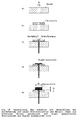
- Fig. 2 shows the construction variants a), b) and c) of metal housing and glass insulator.
- variant a) after Fig. 2 corresponds to the glass feedthrough used in the bursting test.
- the connection of the glass insulation is subjected to shear, and destroyed at the pressure of 1100 to 1500 bar and in this particular example of 1344 bar.
- the insulator is tapered as variant b) in FIG Fig.2 executed.
- variant c) A novel approach is shown in variant c), in which a laminar insulation is used.
- the load acts in the same direction as the adhesive force and thus presses the insulation against the body.
- the construction variant c) supports the adhesive force and the tightness under load due to the design. Because of this advantageous construction compared to the prior art, variant c) is followed up according to FIG.
- the distinguishing feature of the novel design variant for the current feedthrough in comparison to the prior art is the laminar layer structure, which can be manufactured with microtechnical processes and is optimized with regard to the occurring mechanical stresses.
- the components of the electrical feedthrough should basically consist of electrical contacts and insulators.
- electrical contact pins and insulator different materials are used as electrical contact pins and insulator, however, the choice of materials for the high pressure range up to 5,000 bar and beyond is severely limited.
- the anodic bonding of silicon and glass has proven its worth, above all because of the robustness and interlayer freedom. Similar to the anodic bonding of silicon and glass, there are also metals that are anodically bondable with glass [2]. As functional material for the contact pins of the novel current feedthrough, metal is better suited as an electrical conductor than the semiconductor silicon. Similarly, metal is preferable as a construction material for the housing as a mechanically loaded part with sealing function.
- the literature mainly mentions nickel alloys such as Invar or Kovar, but also special titanium alloys as anodically bondable metals [3].
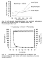
- Fig. 4 shows the residual stresses occurring during anodic bonding of various metal-glass compounds depending on the process temperature.
- the total bond voltage drops across the space charge zone and the air gap between metal and glass. This results in very high electrostatic forces, which compress the metal and glass surface to atomic distance, so that chemical bonds form by oxygen bridges in the form of Fe-O-Si.
- Fig. 5 shows a time-based representation of the parameters temperature, voltage and current during the anodic bonding.
- the characteristic of the Anodic Bonding current curve is the known current curves Comparable when bonding silicon and glass.
- most promising bond parameters 400 ° C and 1900 V, an initial current flow of up to 400 pA ( Fig. 5 ).
- the current drops on the characteristic bonding current curve. Achieving this final value of the current flow after approx. 10 minutes shows the completion of a successful bonding process.
- a tensile test of the anodized bond demonstrates the mechanical stability of the interconnect technology. At a tensile load of 6.3 MPa, the glass ruptures while the joint remains intact. The Anodisch bonded joint is therefore more stable than the weakest starting material.
- Fig. 6 shows the step-by-step manufacturing process of the functional patterns of the novel high-pressure current feedthrough.
- the anodic bonding of Kovar and glass is used to connect the glass insulator to the metal housing.
- the glass insulator is bonded to the Kovar body, which is already provided with four holes for contact feedthrough. Subsequently, the through-holes in the already bonded glass are introduced by means of ultrasonic processing ( Fig. 6b ). This procedure saves the alignment process between Kovar and glass.
- the application of the electrodes to the insulator by means of two-sided anodic bonding is also possible when Kovar is selected as the electrode material.
- the second bonding operation with opposite current direction requires the mechanical processing and provision of the electrodes.
- These time-consuming preparation steps for polishing and cleaning the surfaces, as well as the alignment can be saved by a galvanic step for growing the electrodes.
- the contact is integrated directly into the electroplating process. Insulated copper enameled wires are inserted into the through-holes and directly contacted and fixed during sputtering of the copper starting layer required for electroplating ( Fig. 6c ).
- the electrode geometry is masked by Sputtering process set.
- the subsequently electrodeposited nickel electrodes ( Fig. 6d ) can be contacted by galvanic gilding directly by wire bonding.
- the entire process flow also shows Fig. 15 ,
- the static pressure is applied at the high pressure measuring station by means of silicone oil as pressure coupling medium.
- silicone oil as pressure coupling medium.
- a reference sensor records the loads.
- the static load of 5,000 bar is held for about 5 minutes.
- the functional pattern of the novel implementation has the required mechanical stability and shows no leakage.
- the novel procedure has passed both the static pressure test at 5,000 bar and the 36,000 load changes at 1,000 bar without any metrologically or visually recognizable restrictions.
- the contact resistance of a feedthrough is less than 1 ⁇ , in which case the largest part of the resistance falls on the small diameter copper enamel wire.
- the insulation resistance between electrode and glass base or the electrodes with each other is greater than 20 M ⁇ .
- the miniaturization of the current feedthrough can significantly increase the pressure stability by means of laser-produced through-holes with a maximum diameter of 50 ⁇ m. This would then pressure Stabilities of significantly more than 5,000 bar, possibly even up to 10,000 bar possible. The batch compatibility of the manufacturing process and the associated increase and assurance of the reproducible quality should be ensured.
- the anodic bonding of insulators in particular glass and metal, is regarded as one of the best connection solutions, in particular in order to also ensure stability under pressure fluctuations.
- any combination of the combinations of combinations shown in the following table may also be used.
- Table 2 Anodic bondable metals and glasses metal Chemical composition Kovar 54% Fe, 29% Ni, 17% Co Invar 64% Fe. 36% Ni Alloy 42 58% Fe. 42% Ni titanium Glass Chemical composition Borofloat 33 81% SiO 2 , 13% B 2 O 3 , 4% Na 2 O. 2% Al 2 O 3
- the metal socket of the electrical feedthrough is to be fastened in a metal housing on the high-pressure measuring station.
- the material of the metal base must be mechanically processed, for example turning, milling, lapping and drilling.
- a theoretical estimation determines a relationship between the height of the galvanized nickel electrode h and the radius of the hole in the glass insulator r (h> r).
- Ultrasonic processing drills holes with a radius of 250 ⁇ m into the glass.
- the corresponding minimum height of the nickel electrode is thus 250 microns.
- the nickel can only be previously galvanized on glass, then the nickel layer can be mechanically processed.
- anodic Bonding Kovar can be easily realized as a metal base, since Kovar can be processed before the anodic bonding.
- the electrically conductive parts can be divided into two parts, electrodes and contact pins.
- solution D is better than solution A, because in the galvanic coating, the contact pins can be introduced simultaneously to the nickel electrodes. With the solution A, the contact pins must be contacted after the anodic bonding to the electrode.
- Another aspect of the invention relates to bonding.
- an optimized fixture was developed as part of an anodic bonding apparatus. This part is in Fig. 14 shown
- This clamping device allows a more homogeneous bonding at the contact surfaces of insulator and metal.
- the device has a regulation of the pressure (with detection of the expansion of the materials) and devices for setting very flat transients of voltage and temperature.
- a particularly advantageous embodiment provides the anodic bonding of thick Kovar and glass.
- a variant of the manufacturing method according to the invention according to the invention provides for alternating voltage for double-sided bonding of the insulator (for example glass).
- the AC voltage bonds two sides of the glass simultaneously with Kovar.
Landscapes
- Chemical & Material Sciences (AREA)
- Analytical Chemistry (AREA)
- Physics & Mathematics (AREA)
- General Physics & Mathematics (AREA)
- Measuring Fluid Pressure (AREA)
Priority Applications (2)
| Application Number | Priority Date | Filing Date | Title |
|---|---|---|---|
| EP11184445.2A EP2579013A1 (fr) | 2011-10-07 | 2011-10-07 | Invention concernant des traversées de courant alimentées par pression |
| PCT/EP2012/069690 WO2013050513A1 (fr) | 2011-10-07 | 2012-10-05 | Invention concernant des traversées de courant sous pression |
Applications Claiming Priority (1)
| Application Number | Priority Date | Filing Date | Title |
|---|---|---|---|
| EP11184445.2A EP2579013A1 (fr) | 2011-10-07 | 2011-10-07 | Invention concernant des traversées de courant alimentées par pression |
Publications (1)
| Publication Number | Publication Date |
|---|---|
| EP2579013A1 true EP2579013A1 (fr) | 2013-04-10 |
Family
ID=47088813
Family Applications (1)
| Application Number | Title | Priority Date | Filing Date |
|---|---|---|---|
| EP11184445.2A Withdrawn EP2579013A1 (fr) | 2011-10-07 | 2011-10-07 | Invention concernant des traversées de courant alimentées par pression |
Country Status (2)
| Country | Link |
|---|---|
| EP (1) | EP2579013A1 (fr) |
| WO (1) | WO2013050513A1 (fr) |
Families Citing this family (1)
| Publication number | Priority date | Publication date | Assignee | Title |
|---|---|---|---|---|
| US9208929B2 (en) * | 2013-09-20 | 2015-12-08 | Schott Corporation | GTMS connector for oil and gas market |
Citations (5)
| Publication number | Priority date | Publication date | Assignee | Title |
|---|---|---|---|---|
| JPH10325772A (ja) * | 1997-05-27 | 1998-12-08 | Nissan Motor Co Ltd | 半導体圧力センサおよびその製造方法 |
| JPH1114479A (ja) * | 1997-06-19 | 1999-01-22 | Nissan Motor Co Ltd | 半導体圧力検出装置 |
| EP1069419A2 (fr) * | 1999-07-16 | 2001-01-17 | Yamatake Corporation | Capteur de pression et son procédé de fabrication |
| EP1369879B1 (fr) | 2002-06-06 | 2007-08-29 | IL Metronic Sensortechnik GmbH Ilmenau | Traversées haute-pression pour les composants isolants de parois d'un récipient sous pression |
| DE102006054843A1 (de) * | 2006-10-10 | 2008-04-17 | Electrovac Ag | Elektrische Durchführung, insbesondere für Druckanwendungen, sowie Verfahren zum Herstellen einer solchen Durchführung |
-
2011
- 2011-10-07 EP EP11184445.2A patent/EP2579013A1/fr not_active Withdrawn
-
2012
- 2012-10-05 WO PCT/EP2012/069690 patent/WO2013050513A1/fr active Application Filing
Patent Citations (5)
| Publication number | Priority date | Publication date | Assignee | Title |
|---|---|---|---|---|
| JPH10325772A (ja) * | 1997-05-27 | 1998-12-08 | Nissan Motor Co Ltd | 半導体圧力センサおよびその製造方法 |
| JPH1114479A (ja) * | 1997-06-19 | 1999-01-22 | Nissan Motor Co Ltd | 半導体圧力検出装置 |
| EP1069419A2 (fr) * | 1999-07-16 | 2001-01-17 | Yamatake Corporation | Capteur de pression et son procédé de fabrication |
| EP1369879B1 (fr) | 2002-06-06 | 2007-08-29 | IL Metronic Sensortechnik GmbH Ilmenau | Traversées haute-pression pour les composants isolants de parois d'un récipient sous pression |
| DE102006054843A1 (de) * | 2006-10-10 | 2008-04-17 | Electrovac Ag | Elektrische Durchführung, insbesondere für Druckanwendungen, sowie Verfahren zum Herstellen einer solchen Durchführung |
Non-Patent Citations (3)
| Title |
|---|
| BRIAND, D., WEBER, P., DE ROOIJ, N.F.: "Metal to glass anodic bonding for microsystems packaging", TRANSDUCERS 2003 - THE 12TH INTERNATIONAL CONFERENCE ON SOLID STALE SENSORS ACTUATORS AND MICROSYSTEMS, 8 June 2003 (2003-06-08) |
| DZIUBAN, J.A.: "Bonding in microsystem technology", 2006, SPRINGER |
| HEINICKEL, P., WERTHSCHÜTZKY, R.: "Functionality of a novel overload resistant silicon high pressure sensing element", IEEE TRANSDUCERS CONFERENCE 2009 PROCEEDING, 21 June 2009 (2009-06-21) |
Also Published As
| Publication number | Publication date |
|---|---|
| WO2013050513A1 (fr) | 2013-04-11 |
Similar Documents
| Publication | Publication Date | Title |
|---|---|---|
| EP1897588B1 (fr) | Conducteurs tranversants | |
| EP1393386B1 (fr) | Materiau de passivation pour composant electrique et composant piezo-electrique a structure multicouche | |
| EP0189492B1 (fr) | Méthode de fabrication d'un transducteur de mesure pour mesurer des grandeurs mécaniques | |
| DE102010021764B4 (de) | Verfahren zur Niedertemperatur Drucksinterverbindung zweier Verbindungspartner | |
| EP1897589A2 (fr) | Passage électrique | |
| EP2433105A1 (fr) | Composant céramique doté d'au moins un passage électrique, procédé de fabrication et capteur de pression équipé d'un tel composant | |
| WO1990011610A1 (fr) | Traversee electroconductrice et son procede de fabrication | |
| EP1527483B1 (fr) | Electrode externe disposee sur un actionneur piezoceramique multicouche | |
| EP1920476B1 (fr) | Ensemble comprenant un actionneur piezoelectrique | |
| WO2015082145A1 (fr) | Capteur de pression différentielle | |
| DE102014119111A1 (de) | Druckmesszelle | |
| DE102014117911A1 (de) | Druckmesszelle | |
| EP2579013A1 (fr) | Invention concernant des traversées de courant alimentées par pression | |
| DE3608010A1 (de) | Verfahren zum herstellen einer elektrisch leitenden klebverbindung | |
| DE10065495A1 (de) | Leistungshalbleitermodul | |
| DE102010030156A1 (de) | Keramischer Drucksensor | |
| EP1475623B1 (fr) | Dispositif de mesure de pression avec connection transversale et procédé de connection | |
| EP2755249B1 (fr) | Capteur piézoélectrique et procédé de fabrication d'un dispositif piézoélectrique | |
| EP2802766B1 (fr) | Module d'actionnement muni d'un actionneur multicouche agencé dans un boîtier et présentant un courant de fuite extrêmement bas constant au niveau de la surface de l'actionneur | |
| WO2019154594A1 (fr) | Capteur de pression différentielle | |
| WO2011127889A2 (fr) | Traversée d'un conducteur électrique | |
| EP1369879B1 (fr) | Traversées haute-pression pour les composants isolants de parois d'un récipient sous pression | |
| DE102011003397B4 (de) | Glas-Titan-Dichtung und Verfahren zur Herstellung einer Glas-Titan-Dichtung | |
| EP3078644B1 (fr) | Procédé de fabrication d'une traversée en verre avec tiges de contact | |
| DE102009020163B4 (de) | Verfahren zum zwischenschichtfreien Verbinden von Substraten, Vorrichtung zur Durchführung einer Plasmabehandlung sowie deren Verwendung |
Legal Events
| Date | Code | Title | Description |
|---|---|---|---|
| PUAI | Public reference made under article 153(3) epc to a published international application that has entered the european phase |
Free format text: ORIGINAL CODE: 0009012 |
|
| AK | Designated contracting states |
Kind code of ref document: A1 Designated state(s): AL AT BE BG CH CY CZ DE DK EE ES FI FR GB GR HR HU IE IS IT LI LT LU LV MC MK MT NL NO PL PT RO RS SE SI SK SM TR |
|
| AX | Request for extension of the european patent |
Extension state: BA ME |
|
| 17P | Request for examination filed |
Effective date: 20131010 |
|
| RBV | Designated contracting states (corrected) |
Designated state(s): AL AT BE BG CH CY CZ DE DK EE ES FI FR GB GR HR HU IE IS IT LI LT LU LV MC MK MT NL NO PL PT RO RS SE SI SK SM TR |
|
| STAA | Information on the status of an ep patent application or granted ep patent |
Free format text: STATUS: THE APPLICATION IS DEEMED TO BE WITHDRAWN |
|
| 18D | Application deemed to be withdrawn |
Effective date: 20150501 |