EP2579012A2 - Method and apparatus for measuring residual stresses in a component - Google Patents
Method and apparatus for measuring residual stresses in a component Download PDFInfo
- Publication number
- EP2579012A2 EP2579012A2 EP12186290.8A EP12186290A EP2579012A2 EP 2579012 A2 EP2579012 A2 EP 2579012A2 EP 12186290 A EP12186290 A EP 12186290A EP 2579012 A2 EP2579012 A2 EP 2579012A2
- Authority
- EP
- European Patent Office
- Prior art keywords
- workpiece
- stresses
- residual
- measuring
- deformation
- Prior art date
- Legal status (The legal status is an assumption and is not a legal conclusion. Google has not performed a legal analysis and makes no representation as to the accuracy of the status listed.)
- Withdrawn
Links
- 238000000034 method Methods 0.000 title claims abstract description 27
- 238000009826 distribution Methods 0.000 claims abstract description 8
- 238000005259 measurement Methods 0.000 claims description 16
- 239000000463 material Substances 0.000 claims description 13
- 230000000750 progressive effect Effects 0.000 abstract 1
- 238000004519 manufacturing process Methods 0.000 description 5
- 239000000523 sample Substances 0.000 description 4
- 238000003754 machining Methods 0.000 description 3
- 238000010586 diagram Methods 0.000 description 2
- 230000000712 assembly Effects 0.000 description 1
- 238000000429 assembly Methods 0.000 description 1
- 238000005452 bending Methods 0.000 description 1
- 230000009286 beneficial effect Effects 0.000 description 1
- 230000006835 compression Effects 0.000 description 1
- 238000007906 compression Methods 0.000 description 1
- 238000005520 cutting process Methods 0.000 description 1
- 238000006073 displacement reaction Methods 0.000 description 1
- 238000005553 drilling Methods 0.000 description 1
- 239000002184 metal Substances 0.000 description 1
- 238000005096 rolling process Methods 0.000 description 1
- 238000004904 shortening Methods 0.000 description 1
Images

Classifications
-
- G—PHYSICS
- G01—MEASURING; TESTING
- G01N—INVESTIGATING OR ANALYSING MATERIALS BY DETERMINING THEIR CHEMICAL OR PHYSICAL PROPERTIES
- G01N3/00—Investigating strength properties of solid materials by application of mechanical stress
- G01N3/20—Investigating strength properties of solid materials by application of mechanical stress by applying steady bending forces
-
- G—PHYSICS
- G01—MEASURING; TESTING
- G01N—INVESTIGATING OR ANALYSING MATERIALS BY DETERMINING THEIR CHEMICAL OR PHYSICAL PROPERTIES
- G01N3/00—Investigating strength properties of solid materials by application of mechanical stress
- G01N3/58—Investigating machinability by cutting tools; Investigating the cutting ability of tools
-
- G—PHYSICS
- G01—MEASURING; TESTING
- G01L—MEASURING FORCE, STRESS, TORQUE, WORK, MECHANICAL POWER, MECHANICAL EFFICIENCY, OR FLUID PRESSURE
- G01L5/00—Apparatus for, or methods of, measuring force, work, mechanical power, or torque, specially adapted for specific purposes
- G01L5/0047—Apparatus for, or methods of, measuring force, work, mechanical power, or torque, specially adapted for specific purposes measuring forces due to residual stresses
-
- G—PHYSICS
- G01—MEASURING; TESTING
- G01B—MEASURING LENGTH, THICKNESS OR SIMILAR LINEAR DIMENSIONS; MEASURING ANGLES; MEASURING AREAS; MEASURING IRREGULARITIES OF SURFACES OR CONTOURS
- G01B21/00—Measuring arrangements or details thereof, where the measuring technique is not covered by the other groups of this subclass, unspecified or not relevant
- G01B21/32—Measuring arrangements or details thereof, where the measuring technique is not covered by the other groups of this subclass, unspecified or not relevant for measuring the deformation in a solid
-
- G—PHYSICS
- G01—MEASURING; TESTING
- G01N—INVESTIGATING OR ANALYSING MATERIALS BY DETERMINING THEIR CHEMICAL OR PHYSICAL PROPERTIES
- G01N19/00—Investigating materials by mechanical methods
- G01N19/06—Investigating by removing material, e.g. spark-testing
Definitions
- the present invention is concerned with a method of measuring residual stresses in a component. More specifically, the present invention is concerned with a method of measuring through-thickness residual stresses in a engineering components, particularly of metal, which stresses have arisen from a manufacturing operation such as roll forming.
- Known methods of measuring residual stresses involved techniques such as slitting and deep hole drilling, in which a strain gauge is used to measure the strain within the component and as such determine the residual stress at that point. These techniques require specialist equipment and strain gauges, both of which are not generally available in a manufacturing environment, and instead are laboratory based systems. Therefore the determination of a residual stress field is a time consuming and costly process involving transport of the component to be examined to a suitable facility.
- a method of measuring through-thickness residual stresses in a component comprising the steps of:
- the method comprises the steps of, following the step of measuring the deformation of the workpiece:
- the steps of re-clamping, further material removal, further measurement and determination of further stresses are repeated to form a through-thickness residual stress distribution in the workpiece.
- the step or steps of measuring are performed at the third position.
- an apparatus for measurement of residual through-thickness stresses in a metallic component comprising:
- the deflection measurement apparatus is positioned at the same position between the clamps as the machine tool.
- the deflection measurement apparatus is arranged to be positioned on an opposite side of the workpiece to the machine tool in use.
- a workpiece 10 has been formed by a known manufacturing process such as roll forming.
- a stress plot 12 shows how the residual stresses vary throughout the thickness of the workpiece 10, ranging from compression (C) to tension (T).
- C compression
- T tension
- the stress plot is symmetrical about the longitudinal axis of the workpiece L and, as such, the stresses are balanced such that the workpiece is geometrically stable in this condition (in other words the residual stresses are not observable from a deformation in the material).
- performing a machining operation by taking cuts as shown by cut lines 14 and 16 will produce an asymmetric stress distribution 12 and therefore, consequently, a deflection of the workpiece 10.
- the asymmetry of the stress distribution as a result will induce bending stress upon the workpiece 10.
- the degree of residual strain can be measured.
- FIG. 2 an apparatus 18 for performing the method of the present invention is shown.
- a machine table 20 has a jig base 22 installed thereon, having a first support 24 and a second support 26 extending at opposite ends thereof.
- the supports 24, 26 are spaced apart by a distance D and are configured to receive the workpiece 10 (for example their relative spacing may be adjustable to provide a suitable support for the workpiece 10).
- Each support 24, 26 vertically supports the workpiece 10.
- a deflection probe 28 extends from the jig base 22 upwardly into contact with the workpiece 10 at a position intermediate the supports 24, 26, and is arranged to measure any deflection in the workpiece.
- Each clamp assembly 30, 32 comprises a clamp member 34 arranged to clamp the workpiece 10 between it and the relevant support.
- the clamp member 34 is connected to a cylinder 36 which sits on a piston 38 and can be moved up and down by a lever 40 in order to clamp and release the workpiece 10.
- a machine tool 42 can be lowered onto the upper surface of the workpiece 10 at the corresponding position to the deflection probe 28.
- the machine tool 42 is capable of taking sequential cuts of a known distance into the workpiece 10 and, as such, comprises a motion transducer in order to record the depth of cut into the workpiece 10.
- clamps 32 may be automatically activated by a computer controlled actuator, as will be described in more detail below.
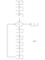
- FIG. 3 an example method in accordance with the present invention is shown as a flow diagram.
- step 44 the jig and workpiece are set up such that the workpiece 10 is clamped within the apparatus 18.
- cutting conditions are manually inputted into the machining sensor or control computer.
- n is multiplied by the depth of cut d, and the machine tool 42 is advanced into the workpiece 10 by a distance of n x d from the workpiece's original top surface datum.
- the clamp 32 is released by the control computer.
- the deflection probe 28 is used to measure the deflection of the workpiece 10. This is stored in the computer.
- clamp 32 is reapplied such that the deflection probe returns to zero.
- n n+1, at which point the process returns to step 50.
- the stresses throughout the workpiece may be calculated as follows:
- the maximum deformed distance can be calculated.
- the residial stresses at the cut depth can then be calculated.
- the process may be controlled by a CNC system in which control is passed to the apparatus shown in Figure 2 and the results, i.e. deflection measurements, are fed back to the PC for analysis.
- the process can be undertaken manually with the user manually clamping and unclamping the clamp 32 and taking appropriate measurements using a manual measuring apparatus, reclamping and remachining.
- the process may be used on vertical and horizontal bed tables.
Landscapes
- Physics & Mathematics (AREA)
- General Physics & Mathematics (AREA)
- Biochemistry (AREA)
- Life Sciences & Earth Sciences (AREA)
- Chemical & Material Sciences (AREA)
- Analytical Chemistry (AREA)
- Health & Medical Sciences (AREA)
- General Health & Medical Sciences (AREA)
- Immunology (AREA)
- Pathology (AREA)
- Investigating Strength Of Materials By Application Of Mechanical Stress (AREA)
- A Measuring Device Byusing Mechanical Method (AREA)
- Turning (AREA)
- Automatic Control Of Machine Tools (AREA)
- Length Measuring Devices With Unspecified Measuring Means (AREA)
Abstract
Description
- The present invention is concerned with a method of measuring residual stresses in a component. More specifically, the present invention is concerned with a method of measuring through-thickness residual stresses in a engineering components, particularly of metal, which stresses have arisen from a manufacturing operation such as roll forming.
- Manufacturing operations such as roll forming produce through-thickness residual stresses in components. Such stresses are not immediately apparent because they tend to be symmetrical through the thickness of the billet (and therefore produce no net strain). Residual stresses are problematic when the component is in-use because applied loading may cause stresses within the component which are higher than expected. Further, if the component is to be machined to size post-rolling, residual stresses may cause unexpected distortion following machining.
- It is beneficial to be able to measure these residual stresses, so that they can be taken into account when the component is in use, or subsequently machined. This avoids any unexpected shortening of component life because of unexpectedly high stresses, and also allows the residual stresses to be accounted for when the component is manufactured to avoid distortion.
- Known methods of measuring residual stresses involved techniques such as slitting and deep hole drilling, in which a strain gauge is used to measure the strain within the component and as such determine the residual stress at that point. These techniques require specialist equipment and strain gauges, both of which are not generally available in a manufacturing environment, and instead are laboratory based systems. Therefore the determination of a residual stress field is a time consuming and costly process involving transport of the component to be examined to a suitable facility.
- It is an aim of this invention to mitigate the above disadvantages by providing a method which can be applied using existing manufacturing equipment, and does not require significant specialist equipment.
- According to a first aspect of the present invention there is provided a method of measuring through-thickness residual stresses in a component comprising the steps of:
- clamping the workpiece at a first position and a second position, spaced from the first position,
- performing a first material removal operation at a third location intermediate the first and second locations,
- releasing the workpiece at the second position,
- measuring a first deformation of the workpiece,
- determining residual stresses in the workpiece from the first deformation.
- Preferably the method comprises the steps of, following the step of measuring the deformation of the workpiece:
- re-clamping the workpiece at the second position,
- performing a further material removal operation at the third location,
- measuring a further deformation of the workpiece following the further material removal operation,
- determining further residual stresses in the workpiece from the further deformation.
- Preferably the steps of re-clamping, further material removal, further measurement and determination of further stresses are repeated to form a through-thickness residual stress distribution in the workpiece.
- Preferably the step or steps of measuring are performed at the third position.
- According to a second aspect of the present invention there is provided an apparatus for measurement of residual through-thickness stresses in a metallic component comprising:
- a first clamp,
- a second clamp spaced from the first clamp,
- a machine tool configured to perform a material removal operation on a workpiece held by the clamps, at a position between the clamps,
- a deflection measurement apparatus positioned between the first and second clamps.
- Preferably the deflection measurement apparatus is positioned at the same position between the clamps as the machine tool.
- Preferably the deflection measurement apparatus is arranged to be positioned on an opposite side of the workpiece to the machine tool in use.
- An example process and apparatus according to the present invention will now be described with reference to the following drawings, in which:-
-
FIGURE 1 is a schematic side section view of an example workpiece showing an example stress distribution; -
FIGURE 2 is a schematic side view of an apparatus in accordance with the second aspect of the present invention; -
FIGURE 3 is a process diagram of a method in accordance with the present invention. - Turning to
Figure 1 , aworkpiece 10 has been formed by a known manufacturing process such as roll forming. Astress plot 12 shows how the residual stresses vary throughout the thickness of theworkpiece 10, ranging from compression (C) to tension (T). As can be seen, the stress plot is symmetrical about the longitudinal axis of the workpiece L and, as such, the stresses are balanced such that the workpiece is geometrically stable in this condition (in other words the residual stresses are not observable from a deformation in the material). - According to the invention, performing a machining operation by taking cuts as shown by
cut lines asymmetric stress distribution 12 and therefore, consequently, a deflection of theworkpiece 10. The asymmetry of the stress distribution as a result will induce bending stress upon theworkpiece 10. By releasing the workpiece and allowing it to deform under the asymmetric stress, the degree of residual strain can be measured. - Turning to
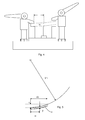
Figure 2 , an apparatus 18 for performing the method of the present invention is shown. - A machine table 20 has a
jig base 22 installed thereon, having afirst support 24 and asecond support 26 extending at opposite ends thereof. Thesupports support workpiece 10. - A
deflection probe 28 extends from thejig base 22 upwardly into contact with theworkpiece 10 at a position intermediate thesupports - On either side of the first and
second supports adjustable clamp assemblies clamp assembly clamp member 34 arranged to clamp theworkpiece 10 between it and the relevant support. Theclamp member 34 is connected to acylinder 36 which sits on apiston 38 and can be moved up and down by alever 40 in order to clamp and release theworkpiece 10. - A
machine tool 42 can be lowered onto the upper surface of theworkpiece 10 at the corresponding position to thedeflection probe 28. Themachine tool 42 is capable of taking sequential cuts of a known distance into theworkpiece 10 and, as such, comprises a motion transducer in order to record the depth of cut into theworkpiece 10. - It will be noted that one or both of the
clamps 32 may be automatically activated by a computer controlled actuator, as will be described in more detail below. - Turning to
Figure 3 , an example method in accordance with the present invention is shown as a flow diagram. - At
step 44, the jig and workpiece are set up such that theworkpiece 10 is clamped within the apparatus 18. - At
step 46, cutting conditions are manually inputted into the machining sensor or control computer. By way of example, the system may be configured to take N=50 cuts of d=1mm each. - At
step 48, the count variable n is initialised at n=1. - At
step 50, the value of n is interrogated to check whether n=N (i.e. whether the system has reached the desired number of cuts). - At
step 52, n is multiplied by the depth of cut d, and themachine tool 42 is advanced into theworkpiece 10 by a distance of n x d from the workpiece's original top surface datum. - At
step 54, theclamp 32 is released by the control computer. - At
step 56, thedeflection probe 28 is used to measure the deflection of theworkpiece 10. This is stored in the computer. - At
step 58,clamp 32 is reapplied such that the deflection probe returns to zero. - At
step 60, n = n+1, at which point the process returns tostep 50. Atstep 50, should n=N (the maximum number of cuts requested) then the process moves ontostep 62, at which point it ends. - Following the aforementioned process, a number of deflections for each value of n is achieved. The residual stresses within the material can be calculated for each of these deflections and, as such, a profile of the stress distribution throughout the
workpiece 10 can be obtained. It will be noted for symmetrical stress distributions as seen inFigure 1 , only half of the thickness of the material 10 needs to be machined. - The stresses throughout the workpiece may be calculated as follows:
- Referring to
Figures 4 and 5 , the deflection of theworkpiece 10 is assumed to approximate to a circle segment governed by the general equation r 2 = x 2 + y 2. - If the radius of curvature is ym, as shown in
Fig. 5 , the measurement is taken at distance xI from the left hand clamp and yI is the measured displacement then:
- In order to obtain f, which is the maximum deformed distance from the reference for a given reference length of specimen If:

- Therefore, using the measured deformation at a point along the
workpiece 10, the maximum deformed distance can be calculated. - Using the maximum deflection of the workpiece, the residial stresses at the cut depth can then be calculated.
- Variations fall within the scope of the present invention. The process may be controlled by a CNC system in which control is passed to the apparatus shown in
Figure 2 and the results, i.e. deflection measurements, are fed back to the PC for analysis. - Alternatively, the process can be undertaken manually with the user manually clamping and unclamping the
clamp 32 and taking appropriate measurements using a manual measuring apparatus, reclamping and remachining. - The process may be used on vertical and horizontal bed tables.
Claims (8)
- A method of measuring through-thickness residual stresses in a component comprising the steps of:clamping the workpiece at a first position and a second position, spaced from the first position,performing a first material removal operation at a third location intermediate the first and second locations,releasing the workpiece at the second position,measuring a first deformation of the workpiece,determining residual stresses in the workpiece from the first deformation.
- A method according to claim 1 comprising the steps of, following the step of measuring the deformation of the workpiece:re-clamping the workpiece at the second position,performing a further material removal operation at the third location,measuring a further deformation of the workpiece following the further material removal operation,determining further residual stresses in the workpiece from the further deformation.
- A method according to claim 2 in which the steps of re-clamping, further material removal, further measurement and determination of further stresses are repeated to form a through-thickness residual stress distribution in the workpiece.
- A method according to any preceding claim in which the step or steps of measuring are performed at the third position.
- A method according to any of claims 1 to 3 in which the step of determining the residual stresses comprises the step of calculating a maximum deformation of the workpiece at a position other than the measurement position.
- An apparatus for measurement of residual through-thickness stresses in a metallic component comprising:a first clamp,a second clamp spaced from the first clamp,a machine tool configured to perform a material removal operation on a workpiece held by the clamps, at a position between the clamps,a deflection measurement apparatus positioned between the first and second clamps.
- An apparatus for measurement of residual through-thickness stresses in a metallic component according to claim 6 in which the deflection measurement apparatus is positioned at the same position between the clamps as the machine tool.
- An apparatus for measurement of residual through-thickness stresses in a metallic component according to claim 7 in which the deflection measurement apparatus is arranged to be positioned on an opposite side of the workpiece to the machine tool in use.
Applications Claiming Priority (1)
| Application Number | Priority Date | Filing Date | Title |
|---|---|---|---|
| GBGB1117343.2A GB201117343D0 (en) | 2011-10-07 | 2011-10-07 | Method and apparatus for measuring residual stresses in a component |
Publications (2)
| Publication Number | Publication Date |
|---|---|
| EP2579012A2 true EP2579012A2 (en) | 2013-04-10 |
| EP2579012A3 EP2579012A3 (en) | 2016-04-27 |
Family
ID=45091703
Family Applications (1)
| Application Number | Title | Priority Date | Filing Date |
|---|---|---|---|
| EP12186290.8A Withdrawn EP2579012A3 (en) | 2011-10-07 | 2012-09-27 | Method and apparatus for measuring residual stresses in a component |
Country Status (7)
| Country | Link |
|---|---|
| US (1) | US8997577B2 (en) |
| EP (1) | EP2579012A3 (en) |
| JP (1) | JP2013083647A (en) |
| CN (1) | CN103076115B (en) |
| CA (1) | CA2791587A1 (en) |
| GB (1) | GB201117343D0 (en) |
| RU (1) | RU2600518C2 (en) |
Families Citing this family (16)
| Publication number | Priority date | Publication date | Assignee | Title |
|---|---|---|---|---|
| CN105339781B (en) * | 2013-08-21 | 2018-12-04 | 联合工艺公司 | Method for in-situ marking for thermo-mechanical structure health monitoring |
| JP5955301B2 (en) * | 2013-11-14 | 2016-07-20 | 株式会社神戸製鋼所 | Residual stress calculation method |
| JP6164065B2 (en) * | 2013-11-29 | 2017-07-19 | 富士通株式会社 | Stress evaluation method and stress evaluation apparatus |
| CN104792440B (en) * | 2014-01-17 | 2017-04-12 | 中国科学院沈阳自动化研究所 | Method of testing three-dimensional residual stress inside laser material increase manufacturing part |
| CN104535226B (en) * | 2014-12-26 | 2017-03-22 | 丁士鹏 | Metal sheet product residual stress testing method |
| CN106840494A (en) * | 2017-01-23 | 2017-06-13 | 宁波哲能精密塑料有限公司 | A kind of internal stress detection method of engineering plastics sheet material |
| CN108225161A (en) * | 2018-02-09 | 2018-06-29 | 中铝材料应用研究院有限公司 | A kind of device for measuring metal thick plate residual stress release deflection |
| DE102018214436B4 (en) * | 2018-08-27 | 2020-07-16 | Universität Stuttgart | Method for determining a stress state in a component |
| CN110243516B (en) * | 2019-06-05 | 2021-01-01 | 中铝材料应用研究院有限公司 | Method for testing residual stress distribution in board in real time |
| CN111103082B (en) * | 2020-01-14 | 2021-04-23 | 中国科学院金属研究所 | Method for improving precision of measuring three-dimensional residual stress by deep hole method |
| CN111141438B (en) * | 2020-01-14 | 2021-04-23 | 中国科学院金属研究所 | A three-dimensional residual stress measurement method by deep hole method |
| CN114088263B (en) * | 2021-10-28 | 2023-05-23 | 广东省特种设备检测研究院(广东省特种设备事故调查中心) | Monitoring method for residual stress of self-reinforced ultrahigh pressure tubular reactor |
| CN115420415B (en) * | 2022-09-29 | 2024-06-25 | 中铝材料应用研究院有限公司 | Thick plate residual stress test all-in-one |
| FR3140422A1 (en) * | 2022-09-30 | 2024-04-05 | Airbus Operations | Method for estimating a residual stress field in a part being machined and machining process using such a method. |
| CN116222857B (en) * | 2023-02-27 | 2025-12-19 | 有研工程技术研究院有限公司 | Device and method for testing distribution of residual stress in plate |
| CN116558689A (en) * | 2023-05-15 | 2023-08-08 | 航鑫材料科技有限公司 | A new device and method for measuring the residual stress of a sample by layer cutting method |
Family Cites Families (29)
| Publication number | Priority date | Publication date | Assignee | Title |
|---|---|---|---|---|
| US3802316A (en) | 1970-04-04 | 1974-04-09 | Kraftwerk Union Ag | Apparatus for machining an arcuate groove |
| DE2016118C3 (en) * | 1970-04-04 | 1978-09-28 | Kraftwerk Union Ag | Process for the measurement of residual stresses in components of the machine or apparatus construction and device for the implementation of this process |
| US4000644A (en) * | 1975-08-20 | 1977-01-04 | Oppenheimer Edgar D | Method and apparatus for testing tensile properties |
| US4567774A (en) * | 1983-04-28 | 1986-02-04 | Battelle Development Corporation | Determining mechanical behavior of solid materials using miniature specimens |
| US4748854A (en) * | 1986-06-10 | 1988-06-07 | Systran Corporation | Fatigue test apparatus |
| JPS6381619A (en) * | 1986-09-26 | 1988-04-12 | Hitachi Ltd | Magnetic head position adjustment device |
| JPS63307324A (en) * | 1987-06-08 | 1988-12-15 | Kawasaki Steel Corp | Method for measuring residual stress of curved pipe |
| SU1566262A1 (en) * | 1988-08-01 | 1990-05-23 | Куйбышевский авиационный институт им.акад.С.П.Королева | Method of determining residual stresses in material of plastically bent part |
| US5193395A (en) * | 1991-12-02 | 1993-03-16 | The United States Of America As Represented By The Administrator Of The National Aeronautics And Space Administration | Method and apparatus for determination of material residual stress |
| JPH06102107A (en) | 1992-08-03 | 1994-04-15 | Daido Steel Co Ltd | Method for measuring residual stress distribution of rolled metal plate |
| DE4244004A1 (en) * | 1992-12-24 | 1994-06-30 | Siemens Ag | Measuring the internal stress in a component |
| JP2655529B2 (en) * | 1995-04-28 | 1997-09-24 | ショーボンド建設株式会社 | Measuring method of existing stress of structural members |
| JPH11194056A (en) * | 1998-01-07 | 1999-07-21 | Mitsubishi Plastics Ind Ltd | Residual stress measurement method |
| NO20002601L (en) * | 1999-10-29 | 2001-04-30 | Holo Tech As | Method and equipment for non-destructive determination of residual stresses by optical holographic interferometer technique |
| US6415486B1 (en) * | 2000-03-01 | 2002-07-09 | Surface Technology Holdings, Ltd. | Method and apparatus for providing a residual stress distribution in the surface of a part |
| GB0019434D0 (en) * | 2000-08-09 | 2000-09-27 | Rolls Royce Plc | A device and method for fatigue testing of materials |
| US6470756B1 (en) * | 2001-02-23 | 2002-10-29 | The Regents Of The University Of California | System and method for measuring residual stress |
| US7320242B2 (en) * | 2002-03-12 | 2008-01-22 | The University Of Akron | Tensile impact apparatus |
| FR2845999A1 (en) * | 2002-10-21 | 2004-04-23 | Michelin Soc Tech | Crosslinkable synthetic polyisoprene with defined tensile test data, useful as a substitute for natural rubber in rubber compositions for making pneumatic tires |
| US6739199B1 (en) * | 2003-03-10 | 2004-05-25 | Hewlett-Packard Development Company, L.P. | Substrate and method of forming substrate for MEMS device with strain gage |
| US7906745B2 (en) * | 2003-12-10 | 2011-03-15 | Lsp Technologies, Inc. | Bend bar quality control method for laser shock peening |
| JP3909773B2 (en) * | 2004-10-27 | 2007-04-25 | 学校法人東海大学 | Wire rod residual stress measuring method and wire rod residual stress measuring device |
| CN2775632Y (en) * | 2004-12-10 | 2006-04-26 | 上海工程技术大学 | Steel belt stress detector |
| KR100517857B1 (en) * | 2004-12-16 | 2005-09-30 | (주)프론틱스 | Evaluating method of the residual stress determining method using the continuous indentation method |
| JP2007303916A (en) | 2006-05-10 | 2007-11-22 | K & T Consultant:Kk | Stress measurement method for structures |
| US7373802B2 (en) * | 2006-08-03 | 2008-05-20 | The State Of Florida, Department Of Transportation | Testing fixture and method for determining toughness of molded plastic components |
| RU2435155C2 (en) * | 2010-02-12 | 2011-11-27 | Открытое акционерное общество "Научно-производственное объединение "Центральный научно-исследовательский институт технологии машиностроения" (ОАО "НПО "ЦНИИТМАШ") | Procedure for determination of residual stresses by characteristics of material hardness |
| CN202393363U (en) * | 2011-12-08 | 2012-08-22 | 东南大学 | High-speed comprehensive test platform for hydraulic power chuck |
| CN102818763B (en) * | 2012-07-30 | 2014-11-19 | 首钢总公司 | A Calculation Method for Residual Stress of Hot-rolled Steel Plate Applicable to Production Site |
-
2011
- 2011-10-07 GB GBGB1117343.2A patent/GB201117343D0/en not_active Ceased
-
2012
- 2012-09-27 EP EP12186290.8A patent/EP2579012A3/en not_active Withdrawn
- 2012-09-29 CN CN201210509624.7A patent/CN103076115B/en not_active Expired - Fee Related
- 2012-10-05 US US13/646,095 patent/US8997577B2/en not_active Expired - Fee Related
- 2012-10-05 JP JP2012223044A patent/JP2013083647A/en active Pending
- 2012-10-05 CA CA2791587A patent/CA2791587A1/en not_active Abandoned
- 2012-10-08 RU RU2012142543/28A patent/RU2600518C2/en not_active IP Right Cessation
Non-Patent Citations (1)
| Title |
|---|
| None |
Also Published As
| Publication number | Publication date |
|---|---|
| RU2600518C2 (en) | 2016-10-20 |
| CN103076115B (en) | 2016-06-22 |
| JP2013083647A (en) | 2013-05-09 |
| GB201117343D0 (en) | 2011-11-23 |
| RU2012142543A (en) | 2014-04-20 |
| US8997577B2 (en) | 2015-04-07 |
| US20130091955A1 (en) | 2013-04-18 |
| CN103076115A (en) | 2013-05-01 |
| CA2791587A1 (en) | 2013-04-07 |
| EP2579012A3 (en) | 2016-04-27 |
Similar Documents
| Publication | Publication Date | Title |
|---|---|---|
| US8997577B2 (en) | Method and apparatus for measuring residual stresses in a component | |
| Rossini et al. | Methods of measuring residual stresses in components | |
| Hill | The slitting method | |
| CN103149024B (en) | The measurement apparatus of three-point bending mechanical property and method | |
| Wang et al. | Influence of restraint conditions on residual stress and distortion of 2219-T8 aluminum alloy TIG welded joints based on contour method | |
| Singh et al. | Comparison of deforming forces, residual stresses and geometrical accuracy of deformation machining with conventional bending and forming | |
| JP5991278B2 (en) | Tension compression test method and apparatus | |
| CN112033796B (en) | Testing tool and testing method for bending mechanical property of honeycomb sandwich structure | |
| CN110487459A (en) | A method for testing internal stress in multiple directions of thick plate | |
| Hayeck et al. | Experimental characterization of steel tubular beam-columns resistance by means of the Overall Interaction Concept | |
| CN110919459B (en) | Method for detecting influence of clamping force on machining deformation of thin-wall part | |
| EP2913115B1 (en) | Bending machine | |
| CN1771099A (en) | Device and method for calibrating a finishing roll device by measuring rods | |
| KR101942938B1 (en) | Out-of-plane bending test device for Vise type connecting bracket and that's testing method | |
| KR101337954B1 (en) | Method and apparatus for measuring extensity of metallic meterial | |
| WO2019101977A1 (en) | Test specimen | |
| KR101942937B1 (en) | Out-of-plane bending test device for Vise type pipe gondola bracket and that's testing method | |
| CN113492322A (en) | Machining process for guide rail surface of heavy long guide rail cross beam | |
| CN214039826U (en) | Static contact inspection frock | |
| CN210570333U (en) | Automatic sample centering device of contact type measuring tape instrument | |
| KR101954827B1 (en) | Out-of-plane bending test device for support plate and that's testing method | |
| CN106247906B (en) | A kind of profile overall size measurement tooling and measurement method | |
| EP1936346B1 (en) | Method for determining the residual stress of a test piece | |
| CN206215791U (en) | A kind of bender locating device | |
| CN213455431U (en) | High-precision roughness tester |
Legal Events
| Date | Code | Title | Description |
|---|---|---|---|
| PUAI | Public reference made under article 153(3) epc to a published international application that has entered the european phase |
Free format text: ORIGINAL CODE: 0009012 |
|
| AK | Designated contracting states |
Kind code of ref document: A2 Designated state(s): AL AT BE BG CH CY CZ DE DK EE ES FI FR GB GR HR HU IE IS IT LI LT LU LV MC MK MT NL NO PL PT RO RS SE SI SK SM TR |
|
| AX | Request for extension of the european patent |
Extension state: BA ME |
|
| PUAL | Search report despatched |
Free format text: ORIGINAL CODE: 0009013 |
|
| AK | Designated contracting states |
Kind code of ref document: A3 Designated state(s): AL AT BE BG CH CY CZ DE DK EE ES FI FR GB GR HR HU IE IS IT LI LT LU LV MC MK MT NL NO PL PT RO RS SE SI SK SM TR |
|
| AX | Request for extension of the european patent |
Extension state: BA ME |
|
| RIC1 | Information provided on ipc code assigned before grant |
Ipc: B21D 5/00 20060101ALI20160322BHEP Ipc: G01L 5/00 20060101AFI20160322BHEP Ipc: G01B 5/30 20060101ALI20160322BHEP Ipc: G01N 19/06 20060101ALI20160322BHEP |
|
| 17P | Request for examination filed |
Effective date: 20160616 |
|
| RBV | Designated contracting states (corrected) |
Designated state(s): AL AT BE BG CH CY CZ DE DK EE ES FI FR GB GR HR HU IE IS IT LI LT LU LV MC MK MT NL NO PL PT RO RS SE SI SK SM TR |
|
| STAA | Information on the status of an ep patent application or granted ep patent |
Free format text: STATUS: THE APPLICATION HAS BEEN WITHDRAWN |
|
| 18W | Application withdrawn |
Effective date: 20170224 |