EP2578992A1 - Geographical azimuth determination referenced to north - Google Patents
Geographical azimuth determination referenced to north Download PDFInfo
- Publication number
- EP2578992A1 EP2578992A1 EP11184180.5A EP11184180A EP2578992A1 EP 2578992 A1 EP2578992 A1 EP 2578992A1 EP 11184180 A EP11184180 A EP 11184180A EP 2578992 A1 EP2578992 A1 EP 2578992A1
- Authority
- EP
- European Patent Office
- Prior art keywords
- goniometer
- gyroscope
- evaluation unit
- determining
- rotary part
- Prior art date
- Legal status (The legal status is an assumption and is not a legal conclusion. Google has not performed a legal analysis and makes no representation as to the accuracy of the status listed.)
- Granted
Links
- 238000005259 measurement Methods 0.000 claims abstract description 88
- 239000013598 vector Substances 0.000 claims abstract description 43
- 230000001133 acceleration Effects 0.000 claims abstract description 34
- 238000000034 method Methods 0.000 claims abstract description 21
- 230000009897 systematic effect Effects 0.000 claims abstract description 10
- 238000004590 computer program Methods 0.000 claims abstract 2
- 238000011156 evaluation Methods 0.000 claims description 45
- 230000008685 targeting Effects 0.000 claims description 20
- 238000009434 installation Methods 0.000 claims description 17
- 230000033001 locomotion Effects 0.000 claims description 13
- 238000012544 monitoring process Methods 0.000 claims description 4
- 230000005540 biological transmission Effects 0.000 claims description 2
- 230000000694 effects Effects 0.000 description 7
- JWDYCNIAQWPBHD-UHFFFAOYSA-N 1-(2-methylphenyl)glycerol Chemical compound CC1=CC=CC=C1OCC(O)CO JWDYCNIAQWPBHD-UHFFFAOYSA-N 0.000 description 6
- 238000004364 calculation method Methods 0.000 description 5
- 230000035945 sensitivity Effects 0.000 description 5
- 230000007774 longterm Effects 0.000 description 4
- 239000007787 solid Substances 0.000 description 4
- 238000012067 mathematical method Methods 0.000 description 3
- 230000004297 night vision Effects 0.000 description 3
- 238000007792 addition Methods 0.000 description 2
- 238000013459 approach Methods 0.000 description 2
- 238000012937 correction Methods 0.000 description 2
- 238000001514 detection method Methods 0.000 description 2
- 238000010586 diagram Methods 0.000 description 2
- 230000007613 environmental effect Effects 0.000 description 2
- 238000012545 processing Methods 0.000 description 2
- 230000001629 suppression Effects 0.000 description 2
- 244000025254 Cannabis sativa Species 0.000 description 1
- 229910000831 Steel Inorganic materials 0.000 description 1
- 235000019892 Stellar Nutrition 0.000 description 1
- 230000002411 adverse Effects 0.000 description 1
- 230000004931 aggregating effect Effects 0.000 description 1
- 230000015572 biosynthetic process Effects 0.000 description 1
- 230000008859 change Effects 0.000 description 1
- 238000004891 communication Methods 0.000 description 1
- 238000010276 construction Methods 0.000 description 1
- 230000001419 dependent effect Effects 0.000 description 1
- 238000009795 derivation Methods 0.000 description 1
- 238000011161 development Methods 0.000 description 1
- 230000018109 developmental process Effects 0.000 description 1
- 235000019800 disodium phosphate Nutrition 0.000 description 1
- 238000006073 displacement reaction Methods 0.000 description 1
- 230000005672 electromagnetic field Effects 0.000 description 1
- 238000005516 engineering process Methods 0.000 description 1
- 239000000835 fiber Substances 0.000 description 1
- 238000001914 filtration Methods 0.000 description 1
- 238000010438 heat treatment Methods 0.000 description 1
- 230000010354 integration Effects 0.000 description 1
- 230000004807 localization Effects 0.000 description 1
- 239000000314 lubricant Substances 0.000 description 1
- 238000004519 manufacturing process Methods 0.000 description 1
- 239000011159 matrix material Substances 0.000 description 1
- NJPPVKZQTLUDBO-UHFFFAOYSA-N novaluron Chemical compound C1=C(Cl)C(OC(F)(F)C(OC(F)(F)F)F)=CC=C1NC(=O)NC(=O)C1=C(F)C=CC=C1F NJPPVKZQTLUDBO-UHFFFAOYSA-N 0.000 description 1
- 230000008569 process Effects 0.000 description 1
- 238000013139 quantization Methods 0.000 description 1
- 239000011435 rock Substances 0.000 description 1
- 239000004576 sand Substances 0.000 description 1
- 239000010959 steel Substances 0.000 description 1
- 239000013589 supplement Substances 0.000 description 1
- 239000000725 suspension Substances 0.000 description 1
- 230000001360 synchronised effect Effects 0.000 description 1
- 230000002123 temporal effect Effects 0.000 description 1
- 230000000007 visual effect Effects 0.000 description 1
Images


Classifications
-
- G—PHYSICS
- G01—MEASURING; TESTING
- G01B—MEASURING LENGTH, THICKNESS OR SIMILAR LINEAR DIMENSIONS; MEASURING ANGLES; MEASURING AREAS; MEASURING IRREGULARITIES OF SURFACES OR CONTOURS
- G01B11/00—Measuring arrangements characterised by the use of optical techniques
- G01B11/26—Measuring arrangements characterised by the use of optical techniques for measuring angles or tapers; for testing the alignment of axes
-
- G—PHYSICS
- G01—MEASURING; TESTING
- G01C—MEASURING DISTANCES, LEVELS OR BEARINGS; SURVEYING; NAVIGATION; GYROSCOPIC INSTRUMENTS; PHOTOGRAMMETRY OR VIDEOGRAMMETRY
- G01C19/00—Gyroscopes; Turn-sensitive devices using vibrating masses; Turn-sensitive devices without moving masses; Measuring angular rate using gyroscopic effects
- G01C19/02—Rotary gyroscopes
- G01C19/34—Rotary gyroscopes for indicating a direction in the horizontal plane, e.g. directional gyroscopes
- G01C19/38—Rotary gyroscopes for indicating a direction in the horizontal plane, e.g. directional gyroscopes with north-seeking action by other than magnetic means, e.g. gyrocompasses using earth's rotation
Definitions
- the invention relates to a north reference goniometer for azimuth alignment determination of a target device according to the preamble of claim 1 and to a method for azimuth angle determination relative to the geographic north pole according to the preamble of claim 10.
- Accurate referencing to the north direction is required in a variety of applications. For example, in the area of navigation and orientation, surveying and observation, a north reference that is as exact as possible (within the scope of the targeted measurement accuracies) is required. Especially in the field - often under adverse environmental conditions with respect to temperature, wind and weather - is to be known, for example, for the cartographic orientation or localization of a target, the north direction as a reference reference in the determination of the azimuth angle. In the following, especially a terrestrial determination of the north direction is described, which is not intended for navigation in moving land, air or sea vehicles.
- the present invention relates primarily to a Nordfindung in goniometers, which set up on earth-bound, at least approximately solid and immovable underground so that the described measurements are made in fixed relation to the Earth coordinate system.
- these earth-bound devices can still - outside the measuring inserts - be mobile in terms of portable, so be suitable for relocation.
- the resulting requirements are, for example, low weight, robustness, battery operation, quick and easy setup and setup, determining the North reference in a short time, etc.
- the present invention provides a north finder in the form of an azimuthally rotatable, north referable pedestal for a targeting unit, such as an observing or measuring instrument, that can be used to augment or supplement a survey or measurement with reliable and accurate north referencing.
- a targeting unit such as an observing or measuring instrument
- a tripod or a tripod attachment whose vertical axis of rotation (also referred to as vertical axis in the measurement) has an angle measurement which is north-referenable according to the invention.
- different observation devices such as binoculars, monoculars, cameras, rangefinders, night vision devices, smaller weapon systems, etc.
- the north-refern evolved azimuth angle measurement according to the invention can also be integrated into the targeting device, so that its rotatable base only has to be set up on earth.
- information of the targeting device, of the azimuth angle meter according to the invention and of other devices can be linked.
- the north-referenced azimuth alignment may be in common with an elevation measurement and a distance measurement are used to determine target coordinates of a targeted object. If the own location is also known, for example via GPS, the destination coordinates can also be determined in a cartographic coordinate system.
- Magnetic compass alignments are usually too inaccurate for such purposes and also the known effects of declination and deviation as well as their interference by the influence of external magnetic and electromagnetic fields, usually allow only conditionally accurate Nord districten.
- the expected accuracy of a magnetic compass measurement is not predictable, and even on the basis of the measurement itself can not be concluded on their accuracy.
- a sufficiently accurate magnetic compass measurement is often not possible.
- the principle has become technically usable in recent years, mainly through further developments in the field of gyroscopic sensors - from the gyroscope gyroscope to the laser ring, fiber to the today's known MEMS gyroscopes, such as the vibrating gyroscopes, for example, according to the principle of HRG (Hemispherical Resonant Gyroscope) or other known gyroscope technologies.
- HRG Hexpherical Resonant Gyroscope
- the underlying measurement principles are basically very old, but have been adapted over and over again to the components and electronic evaluation and data processing components available in the prior art and their characteristics.
- US 4,945,647 shows about a gyrocompass system for terrestrial set up equipment.
- a high-precision inertia sensor is doing a
- a "ring laser gyroscope" is placed on a rotatable platform with the gyroscopic sensitivity axis orthogonal to the axis of rotation, and a possible banking of the platform in two axes using acceleration sensors
- the rotatable platform with the gyroscope is located in a closed housing and is rotated 90 degrees between measurements by a motor and indexed during measurements.
- EP 0 250 608 describes a method for azimuth angle determination in which carried out by means of an accelerometer both a horizontal orientation of the rotary platform, as well as any Sinking during the measurement can be detected or compensated numerically. In order to achieve the required accuracy, the measurement is repeated several times in a position rotated by 180 ° and averaged.
- EP 2 239 540 a device with a gyroscope for mounting on a precisely leveled goniometer is described. Using two gyroscopic measurements in two gyroscope positions rotated by 90 degrees, the instrument can determine the axis of rotation of the earth.
- CA 1 269 874 describes a gyrocompass with a measurement in three, each offset by 120 ° layers with a single gyroscope on a motorized mobile platform which is leveled by a gimbal suspension. Using inclination sensors and measuring the gimbal's rotational position with goniometers, the compass's horizontal orientation is also determined.
- Another object is to achieve sufficient accuracies, e.g. on the order of 1 MIL, using low cost sensors, especially gyroscopes, of the Tactical Grade Gyros.
- a further object is to provide an azimuth angle meter which allows a simple and quick installation, in particular which can be set up without an exact horizontal alignment.
- a fault-tolerant or fail-safe method for azimuth angle determination relative to the geographic north pole is also an object, in particular where a known or determinable alignment accuracy is achieved, for example in the form of an accuracy expectation value.
- the present invention is directed to a north reference goniometer for azimuth alignment of a targeting device.
- the goniometer is constructed with a base for ground-mounted installation and with respect to the base about a standing axis azimuthal rotatable rotary member which is equipped with a Drehwinkelencoder for determining a rotational position of the rotary member about the vertical axis.
- a gyroscope fixed on the rotary part with a measuring direction oriented orthogonally to the standing axis serves for determining a component of the earth rotation vector, and an evaluation unit for determining the azimuth angle of the geographic north pole on the basis of an orientation of the component of the earth rotation vector. It is a non-magnetic determination of the north pole direction.
- an acceleration sensor with a measuring direction orthogonal to the standing axis and to the measuring direction of the gyroscope is fixed on the rotating part.
- the evaluation unit is designed in such a way that the evaluation unit determines the particular component of the earth rotation vector by means of a Acceleration sensor determined sink rate of the goniometer is corrected.
- the evaluation unit is further designed such that a systematic measurement error of the gyroscope is corrected by the evaluation unit by determining measured values of the component of the earth rotation vector in at least three different rotational positions, which are located in at least three predetermined rotational position ranges.
- the evaluation unit can be designed in such a way that rotational positions within the predetermined rotational position ranges can be absorbed by these by means of a user guidance by manual rotation of the rotary part, in particular wherein the rotational position ranges are predetermined in such a way that the systematic measurement error of the gyroscope can be determined.
- the user guidance is controlled by the evaluation unit.
- the goniometer may have a mounted aiming device, which is manually rotatable together with the rotating part of the goniometer, in particular wherein the aiming device can be mounted on the rotating part only in a predetermined rotational position.
- the rotational position ranges can be distributed at least approximately equidistantly around the standing axis of the goniometer, in particular with an average angular distance of at least approximately 120 degrees and a width of the ranges of +/- 10 degrees, especially +/- 5 degrees.
- the evaluation unit can be designed such that, in at least three rotational positions, an inclination of the vertical axis is compared with the aid of measured values of the acceleration sensor a perpendicular can be determined, which is included in the determination of the azimuth angle of the geographic North Pole.
- the evaluation unit can be equipped with a display unit, for example a graphic or text display, LEDs, etc., and / or with an input unit, for example a keyboard, a touchscreen, switches, buttons, etc.
- a display unit for example a graphic or text display, LEDs, etc.
- an input unit for example a keyboard, a touchscreen, switches, buttons, etc.
- an operation of the goniometer (or its evaluation unit) via a, connected by data communication, external control unit in particular, the operation can also be done via a mounted on the goniometer targeting unit.
- the evaluation unit of the goniometer can also be embodied such that in the at least three rotational positions, based on measured values of the acceleration sensor, an inclination of the vertical axis relative to a perpendicular can be determined, which is included in the determination of the azimuth angle of the geographic North Pole.
- the evaluation unit can also be designed such that a latitude of a location of the goniometer can be determined, which is included in the determination of the azimuth angle of the geographic North Pole.
- the latitude can be determined, for example, by means of a GPS, by means of a user query or by means of a targeting of a known target object.
- the goniometer may further comprise an inclinometer, by means of which the installation of the goniometer with an approximately perpendicular orientation of the standing axis, is feasible, in particular with an angular deviation of less than five degrees. Also, the tilt measurement be used for monitoring the establishment of a deplacement of the base by the evaluation, which can be reported to the user to a possible invalidation of Nordreferenzierung.
- the invention also relates to a system for non-magnetic north-referenced targeting consisting of a goniometer according to the invention and a stand for ground-mounted installation of the goniometer.
- the system can also include a targeting device, in particular an observation device, for example a binocular, monocular, night-vision device, etc.
- the targeting device can be equipped with an elevation and distance measuring device.
- An accuracy determination of the ascertained north direction on the basis of the measured values determined by the evaluation unit can also be carried out here and in particular made available to the user.
- the invention also relates to a method for determining the azimuth angle relative to the geographic north pole, in particular with a goniometer according to the invention, comprising determining a rotational position of a rotating part rotatable about a vertical axis relative to a ground-based base, with a Drehwinkelencoder, determining a orthogonal to standing axis aligned in rotational position component of Erdrotationsvektors with a gyroscope fixed on the rotating part and determining the azimuth angle of the geographic North Pole based on an alignment of the components of the Earth rotation vector with an evaluation.
- a determination of a sinking rate of the rotary part with respect to the earth is carried out by the evaluation unit using an acceleration value oriented orthogonally to the orientation of the component of the earth rotation vector determined by the gyroscope with an acceleration sensor fixed on the rotary part. Compensating the determined sinking rate at the particular component of the earth rotation vector, and sequentially manually rotating the rotary member into at least three different rotational positions located in at least three predetermined rotational bearing ranges, is also part of the method. In this case, the determination of the component of the earth rotation vector, determination of the sinking rate and compensation of the sinking rate respectively takes place in the at least three rotational positions.
- the method can be carried out with a manual rotation of the rotating part in a rotational position, which lies in a predetermined range of rotational positions.
- a rotational position ranges are predetermined such that they are at least approximately uniformly distributed around the standing axis and in particular have a range breadth of +/- 10 degrees, especially of +/- 5 degrees.
- Determining an expectation value of an accuracy of determining the azimuth angle of the geographic North Pole by the evaluation unit may also be part of the method.
- a detection of a movement of the base on the basis of measured values of an acceleration sensor by the evaluation unit and output of a warning with respect to any disability due to the azimuth angle of the geographic North Pole may be carried out.
- Determining an inclination of the vertical axis with respect to a perpendicular on the basis of an acceleration measurement and including this inclination in determining the azimuth angle of the geographic North Pole can also be carried out by the evaluation unit.
- the evaluation unit can be controlled by means of program code, which is stored on a machine-readable carrier or computer data signal, embodied by an electromagnetic wave, for carrying out the method according to the invention.
- program code allows a guidance of the user for the manual rotation of a rotary part in rotational positions within at least three predetermined rotational position ranges, and preferably when the program is listed in an evaluation unit of a north reference goniometer.
- Fig. 1 shows an exemplary embodiment of a north reference goniometer 1 according to the invention for the azimuthal orientation determination of a targeting device 10, with a base 2 to the grounded line 11, which in the form of a tripod or tripod , which is placed on the ground 12, is shown.
- the ground-based installation can also be done with alternative means, which ensures a position-fixed connection of the base 2 of the goniometer 1 with the earth coordinate system.
- the base 2 can also be fixed (at least temporarily) firmly on a wall or a rock.
- a tripod similar to that shown, is a commonly used embodiment for mobile field use, which can be adapted to the prevailing environmental conditions.
- the rotary part 3 of the goniometer 1 which can be rotated azimuthally with respect to the base 2 about a standing axis 34 is equipped with a rotary angle encoder for determining a rotary position of the rotary part 3 about the standing axis 34, opposite the base 2.
- a targeting device 10 can be mounted, which directionally fixed with the rotary member, ie in a predetermined, known and reproducible alignment with respect to the standing axis 34 can be mounted.
- the embodiment shown represents a binocular with integrated distance measuring functionality, which can additionally be equipped with a tilt measuring device for determining an elevation angle.
- Other examples of targeting units include monoculars, telescopes, night vision devices, photo or video cameras, small weapon systems, rangefinders, laser pointers, directional antennas, directional microphones, etc.
- the interface between the target unit 10 and the rotary part 3, shown in this embodiment, can be used in addition to the direction determination for the transmission of electrical signals, for example for display and further processing of data of the goniometer. 1 in the target unit 10 or data of the target unit 10 in the goniometer 1.
- the components of this embodiment are dismountable, but alternatively they may be fixedly connected to each other, for example, the goniometer 1 may be in the target unit 10 or integrated into the device for installation 11.
- the rotary part 3 is rotatable through 360 degrees, which allows a flexible installation and alignment of the aiming in any direction. In embodiments which do not allow free rotation by a full 360 degrees, in the installation of the goniometer 1, the target area limited thereby must be considered.
- the goniometer 1 further has an evaluation unit 4 for determining the azimuth angle of the geographic north pole on the basis of an orientation of the component of the earth rotation vector.
- the illustrated embodiment shows a GPS unit 13 that allows geographic location determination of the goniometer 1 location.
- geographical coordinates of a target observed with the target unit 10 can be determined based on the own position known thereby, the azimuth angle determined with the goniometer and a (eg opto-electrical) range finding.
- a determination of the own position can also be carried out, for example, by aiming at known targets with the help of the north-referenced azimuth angle.
- an input your own position for example, based on map data, such as in the form of latitude and longitude information in the system possible.
- Fig. 2 is based on the exemplary embodiment of Fig. 1 the coordinate system relevant for the Nordfindung explained in the following.
- the standing axis 34 around which the goniometer 1 is rotatable (in the same way, the rotary part 3 is rotatable relative to the base 2 about the standing axis 34) is tilted with respect to a vertical or vertical axis 33 by an angle 23.
- the goniometer can also have a display unit in the form of a digital or conventional circular level for this purpose.
- the inclination sensors used for digital leveling can also be used for further functions in addition to the support and monitoring of an at least roughly leveled installation become.
- the inclination measurement for example by means of a two-axis or three-axis MEMS acceleration sensor, can also be used to monitor for any movement, such as transport or displacement of the goniometer, which would necessitate renewed north referencing of the goniometer.
- a related information to the user can help to avoid erroneous measurements.
- the rotational position of the rotating about the standing axis 34 rotatable part 3 relative to the base 2 can be detected with a Drehwinkelencoder.
- the direction of rotation is symbolized by the circular arc arrow 24.
- This may be a relative rotation angle encoder, since a referencing takes place in any case on the basis of the geographic north direction determined according to the invention, but this does not preclude the use of absolute value rotation angle encoders.
- the angular resolution of the specific rotational position must be at least equal to or greater than the desired accuracy of the north referencing or the azimuth angle resolution.
- opto-electrical, magnetic or capacitive rotational angle measuring devices can be used.
- the goniometer 1 has a gyroscope fixed on the rotary part 3 with a measuring direction 31 oriented orthogonally to the standing axis 34, for determining a component of the earth rotation vector.
- the measuring direction 31 is the direction of the rotation vector 21 and perpendicular to the plane of rotation, ie in the direction of the axis of rotation, and indicates the direction of rotation according to the so-called three-finger rule or right-hand rule.
- the amount of the rotation vector 21 gives the angular velocity as Derivation of the rotation angle according to the time.
- the rotation vector 21 is shown on the one hand as a linear vector with a solid arrow and on the other hand as the associated direction of rotation about the axis 31 in the form of a dotted circular arc.
- the acceleration sensor likewise mounted on the rotary part according to the invention is oriented with its measuring direction 32 orthogonal to the measuring direction 31 of the gyroscope, the gyroscope and the acceleration sensor being fixedly connected to one another and to the rotary part 3. It is a high-precision acceleration sensor capable of detecting value changes in the range of a few ⁇ g (9.81 * 10-6 m / s 2 ). However, a limited measuring range is permissible, but this must be in the range of the tolerated deviation from the ideal leveling of the plane of rotation of the rotating part.
- the measured acceleration vector is symbolized by a solid arrow 22, wherein the dotted arrow symbolizes a possible tilting of the base in this direction, which will be discussed in more detail below.
- the described arrangements of the axes relative to one another can be subject to certain deviations due to production, since these can be determined as part of a calibration and can be compensated numerically in the calculations for north referencing.
- pay attention to a stable arrangement of the described sensors rotary encoder, gyroscope, acceleration sensor.
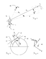
- Fig. 3 shows an exemplary field use of the inventive goniometer 1 in a system with Targeting unit 10 and stand 11, in which with respect to a direction 40 to the geographic North Pole by an azimuth angle aG and an elevation angle e aligned target xS is done.
- Fig. 4 1 illustrates the determination of the geographic north pole 44 according to the invention with the goniometer 1 according to the invention.
- the geographic north pole 44 is defined by the direction of the earth rotation vector rE or a projection rHE of the earth rotation vector rE into the local horizontal plane 42 at a latitude 41
- the in FIG. 3 and FIG. 5 illustrated azimuth angle aG of a device-related coordinate system, such as a surveying or observation device, is defined as an angle between the direction of the device orientation (also called visual axis, line of sight or "sight of sight" and in FIG. 3 and FIG. 5 represented as the x-axis] and the local geographic north direction rHE measured in the horizontal plane.
- a suitable sensor is needed, in particular a high-precision rotation rate sensor, for example a fiber-optic gyroscope, a ring laser Gyroscope, a (hemispheric) resonance gyroscope, or others.
- a high-precision rotation rate sensor for example a fiber-optic gyroscope, a ring laser Gyroscope, a (hemispheric) resonance gyroscope, or others.
- two such gyroscopes can be used with their sensitivity axes in the x- and y-direction (or a biaxial gyroscopic sensor) to perform a simultaneous measurement of the two components rHEx and rHEy of the horizontal component hHE of the earth rotation vector rE.
- a single gyroscope 310 which measures sequentially only in a first x-direction and then in a second y-direction by being rotated as shown by 90 °, so for example, on a rotatable by 90 ° platform moniert and the measuring direction or direction of its measuring vector 31 is aligned accordingly.
- the gyroscope 310 is mounted, for example, on a rotating part, by means of which the sensitivity axis of the gyroscope can be rotated in the plane of the horizontal xy plane, in particular in the x or y direction.
- this can be a freely rotatable platform which can determine the relative angle of rotation h (eg the described 90 degrees) between a sensor orientation in the x-direction of an xS-direction with respect to the earth-based device coordinate system by means of an angle measuring device, eg an angle encoder ,
- an angle measuring device eg an angle encoder
- this can be compared with the typical geometry of a surveying theodolite, on which a gyroscopic sensor is fixedly mounted, so that its measuring axis (at least approximately) orthogonal to the standing axis 34 on the horizontally rotatable member, and with which the measurements described above are performed.
- the rotational angle positions h1 and h2 optimally are as far as possible 90 ° apart, since thus the greatest sensitivity can be achieved.
- Gyroscopes are particularly prone to (especially in the long term) unstable bias, so a non-long-term stable offset, whereby the actual measured values rx 'deviate from the actually predominant values rx, or in other words an offset 0.
- This offset can be regarded as a (at least temporarily) constant measurement signal offset and thus during sufficiently short measurement times as a systematic measurement deviation, or systematic error component o, which can be regarded as approximately constant during the period required for the north determination.
- Gyroscopes are usually even classified according to the size and stability of their offset and divided into tactical or navigation gyroscopes, the latter are usually more sensitive expensive.
- Nordfindung It is therefore desirable to develop a method for Nordfindung, which allows with tactical gyroscopes with high offset values a sufficiently accurate Nordfindung, as is the case in the present invention. There is only a corresponding time stability of the offset, which is a much lower requirement, especially with appropriate compensation of external influences such as temperature changes.
- a 180 ° measurement can be taken, as in Fig. 8 can be applied, but no determination of both components rHEx and rHEy is possible based on such a measurement.
- Fig. 9 and Fig. 10 represented and explained explained below. Since three unknown parameters a, b and o are now sought, at least three measurements rx1, rx2, rx3 from different rotational position angles h1, h2, h3 are also required. An at least approximately uniform division of the measurement positions over the pitch circle is advantageous in order to obtain an optimum contrast of the measured values (in particular of the offset). Other divisions of the three can - with relatively limited accuracy - lead to the desired result, a high-precision division is therefore not required, but the rotational positions must be known to each other accurately, which can be taken as given in a angle-measuring goniometer 1 anyway.
- the rotation 37 can therefore be done manually.
- the requirement for a sufficient accuracy of the angle measurement in this respect results for the expert in an obvious way.
- the same set of parameters can also be applied to measurements in more than three different rotational positions (or multiple measurements in the same rotational positions).
- M cos H 1 sin H 1 1 ⁇ ⁇ ⁇ cos H N sin H N 1
- Fig. 10 again illustrates the measurement described with a single gyroscope 310 in three rotational positions 31a, 31b and 31c in the plane 42 which symbolizes the horizontal plane at the measurement location and is orthogonal to the rotation or standing axis 34. According to the invention, however, this horizontal plane does not have to coincide with high precision with the plane of rotation, as will be explained in more detail below.
- the proportion rHE of the earth rotation vector rE lying in this plane is determined in the three symbolized, (at least approximately) evenly distributed, in this embodiment in particular 120 ° apart rotational positions 31a, 31b and 31c of the gyroscope 31a, in the form of three components of the earth rotation vector.
- the rotary positions 31a, 31b and 31c do not have to assume exact angular positions, but they should lie in the predetermined rotational position ranges 36a, 36b and 36c.
- the adoption of a rotational position within these rotational bearing areas 36a, 36b and 36c means Manual rotation 37 can be assisted by user guidance of the evaluation unit. For example, the user can be indicated by an indication of the achievement of the predetermined rotational position range or the necessary rotation 27.
- the three measurement positions also allow a systematic measurement error of the gyroscope (which is often dominated by a long-term variable measured value offset) to be determined and thus also compensated ,
- a systematic measurement error of the gyroscope which is often dominated by a long-term variable measured value offset
- the gyroscope 310 used is unable to distinguish the rotation of the earth (relative to the stellar reference system) from any other rotational motions, particularly not rotational movements of the gyroscope with respect to the earth.
- each rotational movement of the device relative to the earth is detected by the gyroscope, thus, for example, a sinking of the device with the gyroscope in the ground on which it is placed.
- An in Fig. 11 illustrated sinking 50 would represent a superimposed rotation 21 + 22 for the gyroscope and falsify the measurement result. Since the rate of rotation of the earth to be measured is very low (eg at a horizontal orientation in the 45th latitude about 0.17 degrees per minute), even a very slight sinking 50 or a vibration during the measurement would falsify the measurement result.
- a theodolite or other measuring or targeting unit which is set up for example on a tripod or tripod on typical surfaces 12 such as earth, grass, sand, gravel, etc., most likely to rake with such a sinking 50 be.
- the stand 11 itself may be a source of such minor movements, for example, due to deformation, for example, by (uneven) heating, such as by sunlight, by slow flow of lubricants in the camps, etc.
- the rate of rotation to be measured by the gyroscope is about 10 ° / h.
- a purely gyroscopic measurement is therefore usually not sufficient to ensure a reliable north determination in a sufficiently accurately known or guaranteed accuracy interval.
- a measurement of the sinking rate and compensation of the resulting rotational movement in the gyroscopic measurement is carried out.
- the sink rate is achieved by a correspondingly accurate acceleration measurement at right angles to the gyroscopic measuring direction (see also Fig. 10 ).
- a more precisely so-called micro-G sensor 320 for example in the form of a sensitive acceleration sensor whose sensitivity axis 32a lies in a direction orthogonal to the direction of the measured rotation vector 31a, can be used for this purpose.
- the gravitational vector determined in this case can be used on the one hand for a determination and mathematical compensation of a possibly not entirely horizontal installation of the device, as well as for the determination of a possible sinking as a temporal change of the inclination during the measurement.
- Fig. 14 is the sinking and its determination by means of an acceleration sensor shown graphically.
- Fig. 15 shows an exemplary time course of a measurement signal of an acceleration sensor 61 scaled in micro-radians of the tilt of the exhibition and with the time axis 62 scaled in seconds.
- the acceleration sensor can monitor the positioning of the device and in case of detected by this movement of the device (repositioning, offset, abutment, strong sinking, leaving a leveling range, etc.) automatically prompt the user to a Nordung again.
- an expected value of the achieved accuracy of the north referencing can also be calculated on the basis of the determined data and displayed to the user, preferably as an azimuth angle value. This can be determined from the multilayer measurement according to the invention.
- this horizontal plane does not have to coincide with high precision with the plane of rotation (which corresponds to a deviation of the perpendicular from the standing axis defining the rotation). It is sufficient to know the inclination of the standing axis with respect to the perpendicular, which is given a respective acceleration measurement in the three rotational positions described above. This can be taken into account in the calculations for Nordreferenzierung accordingly.
- Fig. 16 shows an example of a course according to the invention with a Tactical-Grade gyroscope and a micro-G sensor in a time of 2 minutes achievable accuracy of Nordreferenzierung, including any mechanical errors.
- the azimuth error 70 is shown in mil (1/6400 revolution) over several measurements, as well as an RMS (root-mean-square) estimate 71 of the error.
- Fig. 17 shows the error of the north referencing 70 compared to the respective sinking correction 72 over several measurements. This impressively demonstrates the practical significance of the single sink rate correction according to the invention. Even if the goniometer was evidently firmly set up in the measurements shown, the compensated portion of the north referencing error caused by the sinking still exceeds the RMS error of the north pointing achievable according to the invention by a multiple.
Abstract
Description
Die Erfindung betrifft einen nordreferenzierbaren Goniometer zur azimutalen Ausrichtungsbestimmung einer Anzieleinrichtung nach dem Oberbegriff des Anspruchs 1 sowie eine Methode zur Azimutwinkelbestimmung relativ zum geographischen Nordpol nach dem Oberbegriff des Anspruchs 10.The invention relates to a north reference goniometer for azimuth alignment determination of a target device according to the preamble of
Eine genaue Referenzierung zur Nordrichtung ist in vielfältigen Anwendungsfällen erforderlich. Beispielsweise im Bereich der Navigation und Orientierung, der Vermessung und Beobachtung ist eine (im Rahmen der angestrebten Messgenauigkeiten) möglichst exakte Nordreferenz gefordert. Speziell im Feld - oftmals unter widrigen Umgebungsbedingungen bezüglich Temperatur, Wind und Wetter - soll dabei, beispielsweise zur kartographischen Orientierung oder Lokalisierung eines Ziels, die Nordrichtung als Bezugsreferenz bei der Bestimmung des Azimut-Winkels bekannt sein. Im Folgenden wird dabei speziell eine erdgebundene Bestimmung der Nordrichtung beschrieben, welche nicht zur Navigation in sich bewegenden Land-, Luftoder See-Fahrzeugen, gedacht ist. Zwar lassen sich die hier beschriebenen Prinzipien - insbesondere bezüglich der verwendeten Methoden und Kompensationsverfahren - grundsätzlich auch bei sich in Bewegung befindlichen Goniometern nutzen, jedoch wären hierbei weiterführende, komplexere Ansätze erforderlich, insbesondere bezüglich der mathematischen Signalauswertung sowie eine entsprechend schnelle und synchrone Signalerfassung.Accurate referencing to the north direction is required in a variety of applications. For example, in the area of navigation and orientation, surveying and observation, a north reference that is as exact as possible (within the scope of the targeted measurement accuracies) is required. Especially in the field - often under adverse environmental conditions with respect to temperature, wind and weather - is to be known, for example, for the cartographic orientation or localization of a target, the north direction as a reference reference in the determination of the azimuth angle. In the following, especially a terrestrial determination of the north direction is described, which is not intended for navigation in moving land, air or sea vehicles. Although the principles described here-in particular with regard to the methods and compensation methods used-can basically also be used with goniometers in motion, further-reaching, more complex approaches would be required, in particular with regard to the mathematical signal evaluation and a correspondingly fast and synchronous signal acquisition.
Die vorliegende Erfindung betrifft primär eine Nordfindung in Goniometern, welche auf erdgebundenem, zumindest annähernd festem und unbeweglichem Untergrund aufgestellt sind, sodass die beschriebenen Messungen in festem Bezug zum Erdkoordinatensystem durchgeführt werden. Diese erdgebundenen Geräte können aber dennoch - ausserhalb der Messeinsätze - mobil im Sinne von tragbar sein, also auch für Standortwechsel geeignet sein. Daraus resultierende Anforderungen sind beispielsweise geringes Gewicht, Robustheit, Batteriebetrieb, schnelles und einfaches Aufstellen und Einrichten, Bestimmen der Nordreferenz in kurzer Zeit, etc.The present invention relates primarily to a Nordfindung in goniometers, which set up on earth-bound, at least approximately solid and immovable underground so that the described measurements are made in fixed relation to the Earth coordinate system. However, these earth-bound devices can still - outside the measuring inserts - be mobile in terms of portable, so be suitable for relocation. The resulting requirements are, for example, low weight, robustness, battery operation, quick and easy setup and setup, determining the North reference in a short time, etc.
Beispielsweise stellt die vorliegende Erfindung eine Nordfindung in Form eines azimutal drehbaren, nordreferenzierbaren Untersatzes für eine Anzieleinheit, wie etwa eines Beobachtungs- oder Messgeräts, zur Verfügung, mit dessen Hilfe eine Beobachtung bzw. Messung um eine zuverlässige und genaue Nordreferenzierung erweitert oder ergänzt werden kann.For example, the present invention provides a north finder in the form of an azimuthally rotatable, north referable pedestal for a targeting unit, such as an observing or measuring instrument, that can be used to augment or supplement a survey or measurement with reliable and accurate north referencing.
Als einer der möglichen Anwendungsfälle sei hierzu ein Stativ bzw. ein Stativaufsatz genannt, dessen vertikale Drehachse (in der Vermessung auch als Stehachse bezeichnet) über eine entsprechend der Erfindung nordreferenzierbare Winkelmessung verfügt. Auf diesem Stativ bzw. Stativaufsatz können dann unterschiedliche Beobachtungsgeräte, etwa Binokulare, Monokulare, Kameras, Entfernungsmesser, Nachtsichtgeräte, kleinere Waffensysteme, etc. montiert werden. Die erfindungsgemässe nordrefernzierte Azimutwinkelmessung kann alternativ aber auch in die Anzieleinrichtung integriert sein, sodass dessen drehbare Basis nur noch erdverbunden aufgestellt werden muss. Durch entsprechende Datenschnittstellen können Informationen der Anzieleinrichtung, des erfindungsgemässen Azimutwinkelmessers sowie anderer Geräte verknüpft werden. Beispielsweise kann die nordreferenzierte Azimut-Ausrichtung gemeinsam mit einer Elevationsmessung und einer Entfernungsmessung zur Bestimmung von Zielkoordinaten eines angezielten Objekts benutzt werden. Ist weiters, beispielsweise über GPS, der eigene Standort bekannt, können die Zielkoordinaten auch in einem kartographischen Koordinatensystem bestimmt werden.One of the possible applications for this purpose is a tripod or a tripod attachment whose vertical axis of rotation (also referred to as vertical axis in the measurement) has an angle measurement which is north-referenable according to the invention. On this tripod or tripod attachment then different observation devices, such as binoculars, monoculars, cameras, rangefinders, night vision devices, smaller weapon systems, etc. can be mounted. Alternatively, the north-refernzierte azimuth angle measurement according to the invention can also be integrated into the targeting device, so that its rotatable base only has to be set up on earth. By means of corresponding data interfaces, information of the targeting device, of the azimuth angle meter according to the invention and of other devices can be linked. For example, the north-referenced azimuth alignment may be in common with an elevation measurement and a distance measurement are used to determine target coordinates of a targeted object. If the own location is also known, for example via GPS, the destination coordinates can also be determined in a cartographic coordinate system.
Magnetische Kompassausrichtungen sind für derartige Zwecke meist zu ungenau und auch die bekannten Effekte der Deklination und Deviation sowie deren Störbarkeit durch Einflüsse externer magnetischer und elektromagnetischer Felder, erlauben meist nur bedingt genaue Nordweisungen. Zudem ist die zu erwartende Genauigkeit einer Magnetkompassmessung nicht vorherbestimmbar, und auch anhand der Messung selbst kann nicht auf deren Genauigkeit geschlossen werden. Speziell in Gebäuden, Stahlkonstruktionen, Tunneln oder unterirdischen Einrichtungen sowie in der Nähe von elektrischen Anlagen, ist eine hinreichend genaue Magnetkompassmessung vielfach nicht möglich.Magnetic compass alignments are usually too inaccurate for such purposes and also the known effects of declination and deviation as well as their interference by the influence of external magnetic and electromagnetic fields, usually allow only conditionally accurate Nordweisungen. In addition, the expected accuracy of a magnetic compass measurement is not predictable, and even on the basis of the measurement itself can not be concluded on their accuracy. Especially in buildings, steel structures, tunnels or underground facilities as well as in the vicinity of electrical systems, a sufficiently accurate magnetic compass measurement is often not possible.
Neben einer magnetischen Nordfindung, ist auch eine Nordfindung durch Bestimmung der Erddrehachse bekannt, welche per Definition den geographischen Nord- und Südpol verbindet. Dieses Grundprinzip ist schon seit der Entdeckung des zugrunde liegenden Effekts im Jahre 1817, insbesondere seit der Entdeckung des Foucaultschen Pendels durch Jean Bernard Lèon Foucault im Jahre 1851 und der Erfindung des Kreiselkompasses im Jahre 1852 bekannt, worauf auch im Jahre 1876 William Thomson einen entsprechenden Kompass patentierte. Die hierbei zugrunde gelegten physikalischen Prinzipien sind somit in ihrer Basis aus Lehr- und Geschichtsbüchern hinreichend bekannt.In addition to a magnetic Nordfindung, a Nordfindung by determining the Erddrehachse is known, which connects by definition the geographical north and south pole. This basic principle has been known since the discovery of the underlying effect in 1817, especially since the discovery of the Foucault pendulum by Jean Bernard Léon Foucault in 1851 and the invention of the gyrocompass in 1852, whereupon in 1876 William Thomson also designed a corresponding compass patented. The underlying physical principles are thus sufficiently known in their basis from textbooks and history books.
Technisch nutzbar wurde das Prinzip in jüngerer Zeit vor allem durch Weiterentwicklungen im Bereich von gyroskopischen Sensoren - vom Kreisel-Gyroskop zum Laserring-, Faser- bis hin zu den heute bekannten MEMS-Gyroskopen, wie etwa den Vibrationsgyroskopen, beispielsweise nach dem HRG-Prinzip (=Hemispherical Resonant Gyroscope) oder anderen bekannten Gyroskop-Technologien. Durch die stetige Verringerung der Baugrösse und des Gewichts unter Verbesserung der Messgenauigkeit und Zuverlässigkeit, ist der Einsatz von Gyroskopen auch in tragbaren oder mobilen Geräten attraktiv geworden. Die zugrunde liegenden Messprinzipien sind dabei im Grunde jedoch sehr alt, wurde aber immer wieder an die im Stand der Technik verfügbaren Komponenten und elektronischen Auswerte- und Datenverarbeitungskomponenten und deren Charakteristika angepasst.The principle has become technically usable in recent years, mainly through further developments in the field of gyroscopic sensors - from the gyroscope gyroscope to the laser ring, fiber to the today's known MEMS gyroscopes, such as the vibrating gyroscopes, for example, according to the principle of HRG (Hemispherical Resonant Gyroscope) or other known gyroscope technologies. By constantly reducing size and weight while improving accuracy and reliability, the use of gyroscopes has also become attractive in portable or mobile devices. The underlying measurement principles are basically very old, but have been adapted over and over again to the components and electronic evaluation and data processing components available in the prior art and their characteristics.
![]()
![]()
Auch
In
Es sind auch Gerätschaften bekannt, welche mit mehreren, vorzugsweise orthogonal angeordneten Gyroskopen die Nordrichtung bestimmen. Es ist theoretisch auch möglich, mit nur einem einzigen, nicht drehbaren Gyroskop die Nordrichtung zu bestimmen (genauso genommen wird dabei die Ost-West Richtung bestimmt), jedoch erfordert dies zur Erzielung hinreichender Winkelgenauigkeiten auch hochpräzise Gyroskope, insbesondere mit sehr geringem Rauschen, Driften und Bias, welche kostenintensiv, gross und schwer sind, und daher speziell für kostengünstige, portable Geräte für den Feldeinsatz ungeeignet sind.There are also known devices which determine the north direction with a plurality of preferably orthogonally arranged gyroscopes. It is also theoretically possible to determine the north direction with only a single, non-rotatable gyroscope (the east-west direction is also determined), but this requires to achieve sufficient angular accuracy and high-precision gyroscopes, especially with very low noise, drift and Bias, which are costly, large and heavy, and are therefore unsuitable for low cost, portable devices for field use.
Es ist daher eine Aufgabe der vorliegenden Erfindung, einen verbesserten nordreferenzierbaren Azimutwinkelmesser, insbesondere für den Feldeinsatz, bereitzustellen.It is therefore an object of the present invention to provide an improved north-referable azimuth angle meter, especially for field use.
Eine weitere Aufgabe ist dabei Erzielung hinreichender Genauigkeiten, z.B. in der Grössenordnung von 1 MIL, unter der Verwendung von kostengünstigen Sensoren, speziell Gyroskopen, der niedrigeren Genauigkeitslassen ("Tactical Grade Gyros").Another object is to achieve sufficient accuracies, e.g. on the order of 1 MIL, using low cost sensors, especially gyroscopes, of the Tactical Grade Gyros.
Es ist dabei auch eine Aufgabe eine Nordreferenzierung mit der entsprechenden Genauigkeit auch in kurzer Zeit, vorzugsweise in einigen wenigen Minuten oder darunter zu erzielen.It is also an object to achieve a Nordreferenzierung with the appropriate accuracy in a short time, preferably in a few minutes or less.
Eine weitere Aufgabe ist es einen Azimutwinkelmesser bereitzustellen, welcher eine einfache und schnelle Aufstellung erlaubt, insbesondere welcher ohne eine exakte Horizontalausrichtung aufgestellt werden kann.A further object is to provide an azimuth angle meter which allows a simple and quick installation, in particular which can be set up without an exact horizontal alignment.
Es ist auch eine Aufgabe, möglichst wenige, leichte und kleine Komponenten zu verwenden, um eine hohe Mobilität und robuste Konstruktion für den Feldeinsatz zu erzielen. So soll im Gegensatz zu einer vollwertige 6-DOF-Navigationseinheit nur ein einzelnes Gyroskop verwendet werden. Auch auf elektromagnetische Motoren soll dabei verzichtet werden, um ein kleines, leichtes, kostengünstiges und Robustes Goniometer zu erhalten.It is also an objective to use as few, light and small components as possible to achieve high mobility and robust construction for field use. In contrast to a full 6 DOF navigation unit, only a single gyroscope should be used. It should also be dispensed with electromagnetic motors in order to obtain a small, lightweight, cost-effective and robust goniometer.
Auch das Bereitstellen einer fehlertoleranten bzw. fehlersicheren Methode zur Azimutwinkelbestimmung relativ zum geographischen Nordpol ist eine Aufgabe, insbesondere wobei eine bekannte, bzw. bestimmbare Ausrichtungsgenauigkeit erzielt wird, beispielsweise in Form eines Genauigkeitserwartungswertes.The provision of a fault-tolerant or fail-safe method for azimuth angle determination relative to the geographic north pole is also an object, in particular where a known or determinable alignment accuracy is achieved, for example in the form of an accuracy expectation value.
Es ist auch eine Aufgabe einen Azimutwinkelmesser mit einer Online - Statusüberwachung bereitzustellen, welcher im Falle einer (absichtlichen oder unabsichtlichen) Bewegung oder Deplatzierung den Benutzer auf die Notwendigkeit einer Neubestimmung der Nordreferenz hinweist.It is also an object to provide an azimuth goniometer with on-line status monitoring which in case of (deliberate or unintentional) movement or misplacing the user points to the need to redetermine the north reference.
Diese Aufgaben werden durch die Verwirklichung der kennzeichnenden Merkmale der unabhängigen Ansprüche gelöst. Merkmale, die die Erfindung in alternativer oder vorteilhafter Weise weiterbilden, sind den abhängigen Patentansprüchen zu entnehmen.These objects are achieved by the realization of the characterizing features of the independent claims. Features which further develop the invention in an alternative or advantageous manner can be found in the dependent claims.
Die vorliegende Erfindung behandelt einen nordreferenzierbaren Goniometer zur azimutalen Ausrichtungsbestimmung einer Anzieleinrichtung.The present invention is directed to a north reference goniometer for azimuth alignment of a targeting device.
Der Goniometer ist aufgebaut mit einer Basis zur erdverbundenen Aufstellung und einem bezüglich der Basis um eine Stehachse azimutal verdrehbaren Drehteil, welcher mit einem Drehwinkelencoder zur Bestimmung einer Drehlage des Drehteils um die Stehachse ausgestattet ist.The goniometer is constructed with a base for ground-mounted installation and with respect to the base about a standing axis azimuthal rotatable rotary member which is equipped with a Drehwinkelencoder for determining a rotational position of the rotary member about the vertical axis.
Ein auf dem Drehteil fixiertes Gyroskop mit einer orthogonal zur Stehachse ausgerichteten Messrichtung, dient zur Bestimmung einer Komponente des Erdrotationsvektors, und einer Auswerteeinheit zur Bestimmung des Azimutwinkels des geographischen Nordpols anhand einer Ausrichtung der Komponente des Erdrotationsvektors. Es handelt sich dabei um eine nichtmagnetische Bestimmung der Nordpol-Richtung.A gyroscope fixed on the rotary part with a measuring direction oriented orthogonally to the standing axis serves for determining a component of the earth rotation vector, and an evaluation unit for determining the azimuth angle of the geographic north pole on the basis of an orientation of the component of the earth rotation vector. It is a non-magnetic determination of the north pole direction.
Auf dem Drehteil ist erfindungsgemäss ein Beschleunigungssensor mit einer Messrichtung orthogonal zur Stehachse und zur Messrichtung des Gyroskops fixiert.According to the invention, an acceleration sensor with a measuring direction orthogonal to the standing axis and to the measuring direction of the gyroscope is fixed on the rotating part.
Die Auswerteeinheit ist dabei erfindungsgemäss derart ausgebildet, dass durch die Auswerteeinheit die bestimmte Komponente des Erdrotationsvektors um eine anhand des Beschleunigungssensors ermittelte Einsink rate des Goniometers korrigiert wird.According to the invention, the evaluation unit is designed in such a way that the evaluation unit determines the particular component of the earth rotation vector by means of a Acceleration sensor determined sink rate of the goniometer is corrected.
Die Auswerteeinheit ist dabei erfindungsgemäss weiters derart ausgebildet, dass durch die Auswerteeinheit, ein systematischer Messfehler des Gyroskops korrigiert wird, indem Messwerte der Komponente des Erdrotationsvektors in zumindest drei unterschiedlichen Drehlagen, die sich in zumindest drei vorgegebenen Drehlagenbereichen befinden, bestimmt werden.According to the invention, the evaluation unit is further designed such that a systematic measurement error of the gyroscope is corrected by the evaluation unit by determining measured values of the component of the earth rotation vector in at least three different rotational positions, which are located in at least three predetermined rotational position ranges.
Beim Goniometer kann die Auswerteeinheit derart ausgebildet sein, dass durch diese anhand einer Benutzerführung durch manuelles Verdrehen des Drehteils Drehlagen innerhalb der vorgegebenen Drehlagenbereichen einnehmbar sind, insbesondere wobei die Drehlagenbereiche derart vorgegeben sind, dass der systematische Messfehler des Gyroskops bestimmbar ist. Dabei wird die Benutzerführung von der Auswerteeinheit gesteuert.In the case of the goniometer, the evaluation unit can be designed in such a way that rotational positions within the predetermined rotational position ranges can be absorbed by these by means of a user guidance by manual rotation of the rotary part, in particular wherein the rotational position ranges are predetermined in such a way that the systematic measurement error of the gyroscope can be determined. The user guidance is controlled by the evaluation unit.
Das Goniometer kann eine montierte Anzieleinrichtung aufweisen, welche gemeinsam mit dem Drehteil des Goniometers händisch drehbar ist, insbesondere wobei die Anzieleinrichtung lediglich in einer vorgegebenen Drehlage auf dem Drehteil montierbar ist.The goniometer may have a mounted aiming device, which is manually rotatable together with the rotating part of the goniometer, in particular wherein the aiming device can be mounted on the rotating part only in a predetermined rotational position.
Die Drehlagenbereiche können zumindest annähernd äquidistant um die Stehachse des Goniometers verteilt sein, insbesondere mit einem mittleren Winkelabstand von zumindest annähernd 120 Grad und einer Breite der Bereiche von +/- 10 Grad, speziell von +/- 5 Grad.The rotational position ranges can be distributed at least approximately equidistantly around the standing axis of the goniometer, in particular with an average angular distance of at least approximately 120 degrees and a width of the ranges of +/- 10 degrees, especially +/- 5 degrees.
Die Auswerteeinheit kann derart ausgebildet sein, dass in zumindest drei Drehlagen anhand von Messwerten des Beschleunigungssensors eine Neigung der Stehachse gegenüber einer Lotrechten ermittelbar ist, welche bei der Bestimmung des Azimutwinkels des geographischen Nordpols einbezogen wird.The evaluation unit can be designed such that, in at least three rotational positions, an inclination of the vertical axis is compared with the aid of measured values of the acceleration sensor a perpendicular can be determined, which is included in the determination of the azimuth angle of the geographic North Pole.
Die Auswerteeinheit kann mit einer Anzeigeeinheit, beispielsweise einem Grafik- oder Text-Display, LEDs, etc., und/oder mit einer Eingabeeinheit, beispielsweise einer Tastatur, einem Touchscreen, Schaltern, Tastern, etc. ausgestattet sein. Alternativ kann eine Bedienung des Goniometers (bzw. dessen Auswerteeinheit) auch über eine, mittels Datenkommunikation verbundene, externe Bedieneinheit erfolgen, insbesondere kann die Bedienung auch über eine auf dem Goniometer montierte Anzieleinheit erfolgen.The evaluation unit can be equipped with a display unit, for example a graphic or text display, LEDs, etc., and / or with an input unit, for example a keyboard, a touchscreen, switches, buttons, etc. Alternatively, an operation of the goniometer (or its evaluation unit) via a, connected by data communication, external control unit, in particular, the operation can also be done via a mounted on the goniometer targeting unit.
Die Auswerteeinheit des Goniometers kann auch derart ausgebildet sein, dass in den zumindest drei Drehlagen anhand von Messwerten des Beschleunigungssensors eine Neigung der Stehachse gegenüber einer Lotrechten ermittelbar ist, welche bei der Bestimmung des Azimutwinkels des geographischen Nordpols einbezogen wird.The evaluation unit of the goniometer can also be embodied such that in the at least three rotational positions, based on measured values of the acceleration sensor, an inclination of the vertical axis relative to a perpendicular can be determined, which is included in the determination of the azimuth angle of the geographic North Pole.
Die Auswerteeinheit kann auch derart ausgebildet sein, dass eine geographische Breite eines Standortes des Goniometers ermittelbar ist, welche bei der Bestimmung des Azimutwinkels des geographischen Nordpols einbezogen wird. Die geographische Breite kann beispielsweise mittels eines GPS, mittels einer Benutzerabfrage oder mittels einer Anzielung eines bekannten Zielobjekts ermittelbar sein.The evaluation unit can also be designed such that a latitude of a location of the goniometer can be determined, which is included in the determination of the azimuth angle of the geographic North Pole. The latitude can be determined, for example, by means of a GPS, by means of a user query or by means of a targeting of a known target object.
Das Goniometer kann weiters einen Neigungsmesser aufweisen, mittels welchem die Aufstellung des Goniometers mit einer annähernd lotrechten Ausrichtung der Stehachse, durchführbar ist, insbesondere mit einer Winkelabweichung von weniger als fünf Grad. Auch kann die Neigungsmessung für eine Überwachung der Aufstellung auf einen Deplatzierung der Basis durch die Auswerteeinheit genutzt werden, welche auf eine allfällige Invalidierung der Nordreferenzierung dem Benutzer gemeldet werden kann.The goniometer may further comprise an inclinometer, by means of which the installation of the goniometer with an approximately perpendicular orientation of the standing axis, is feasible, in particular with an angular deviation of less than five degrees. Also, the tilt measurement be used for monitoring the establishment of a deplacement of the base by the evaluation, which can be reported to the user to a possible invalidation of Nordreferenzierung.
Die Erfindung betrifft auch ein System zur nichtmagnetisch nordreferenzierten Anzielung bestehend aus einem erfindungsgemässen Goniometer und einem Stativ zur erdverbundenen Aufstellung des Goniometers. Das System kann auch eine Anzieleinrichtung, insbesondere ein Beobachtungsgerät, beispielsweise ein Binokular, Monokular, Nachtsichtgerät, etc. mitumfassen, im speziellen kann die Anzieleinrichtung mit einer Elevations- und Entfernungsmesseinrichtung ausgestattet sein.The invention also relates to a system for non-magnetic north-referenced targeting consisting of a goniometer according to the invention and a stand for ground-mounted installation of the goniometer. The system can also include a targeting device, in particular an observation device, for example a binocular, monocular, night-vision device, etc. In particular, the targeting device can be equipped with an elevation and distance measuring device.
Die Messung zur Nordrichtungsbestimmung soll dabei in kurzer Zeit (vorzugsweise in einigen wenigen Minuten oder gar darunter) erfolgen, aber zugleich mit entsprechender Genauigkeit (z.B. etwa im mil-Bereich (=1/6400 Umdrehung)) der Nordreferenzierung erfolgen. Dabei kann bei der Nordreferenzierung auch in gewissen Grenzen eine erhöhte Genauigkeit gegenüber einer kürzeren Messdauer abgewogen werden.The measurement for the north direction determination should take place in a short time (preferably in a few minutes or even less), but at the same time with a corresponding accuracy (for example in the mil range (= 1/6400 rpm)) of the Nordreferenzierung done. In the case of the north referencing, within certain limits an increased accuracy compared to a shorter measurement duration can be weighed.
Eine Genauigkeitsbestimmung der ermittelten Nordrichtung anhand der ermittelten Messwerte durch die Auswerteeinheit kann dabei ebenfalls durchgeführt und insbesondere dem Benutzer zur Verfügung gestellt werden.An accuracy determination of the ascertained north direction on the basis of the measured values determined by the evaluation unit can also be carried out here and in particular made available to the user.
Die Erfindung betrifft auch eine Methode zur Azimutwinkelbestimmung relativ zum geographischen Nordpol, insbesondere mit einem erfindungsgemässen Goniometer, mit einem Bestimmen einer Drehlage eines gegenüber einer erdverbunden aufgestellten Basis um eine Stehachse drehbaren Drehteils, mit einem Drehwinkelencoder, einem Bestimmen einer orthogonal zu Stehachse in Drehlage ausgerichteten Komponente des Erdrotationsvektors, mit einem auf dem Drehteil fixierten Gyroskop und einem Bestimmen des Azimutwinkels des geographischen Nordpols anhand einer Ausrichtung der Komponenten des Erdrotationsvektors mit einer Auswerteeinheit.The invention also relates to a method for determining the azimuth angle relative to the geographic north pole, in particular with a goniometer according to the invention, comprising determining a rotational position of a rotating part rotatable about a vertical axis relative to a ground-based base, with a Drehwinkelencoder, determining a orthogonal to standing axis aligned in rotational position component of Erdrotationsvektors with a gyroscope fixed on the rotating part and determining the azimuth angle of the geographic North Pole based on an alignment of the components of the Earth rotation vector with an evaluation.
Erfindungsgemäss wird dabei ein Bestimmen einer Einsinkrate des Drehteils bezüglich der Erde anhand eines orthogonal zur Ausrichtung der vom Gyroskop bestimmten Komponente des Erdrotationsvektors orientierten Beschleunigungswerts mit einem auf dem Drehteil fixierten Beschleunigungssensor, durch die Auswerteeinheit ausgeführt. Ein Kompensieren der ermittelten Einsinkrate bei der bestimmten Komponente des Erdrotationsvektors, und ein sequenzielles, manuelles Drehen des Drehteils in zumindest drei unterschiedliche Drehlagen, welche sich in zumindest drei vorgegebenen Drehlagenbereichen befinden, ist auch Teil der Methode. Dabei erfolgt das Bestimmen der Komponente des Erdrotationsvektors, Bestimmen der Einsinkrate und Kompensieren der Einsinkrate jeweiliges in den zumindest drei Drehlagen.According to the invention, a determination of a sinking rate of the rotary part with respect to the earth is carried out by the evaluation unit using an acceleration value oriented orthogonally to the orientation of the component of the earth rotation vector determined by the gyroscope with an acceleration sensor fixed on the rotary part. Compensating the determined sinking rate at the particular component of the earth rotation vector, and sequentially manually rotating the rotary member into at least three different rotational positions located in at least three predetermined rotational bearing ranges, is also part of the method. In this case, the determination of the component of the earth rotation vector, determination of the sinking rate and compensation of the sinking rate respectively takes place in the at least three rotational positions.
Dies ermöglicht ein Bestimmen eines systematischen Messfehlers, insbesondere eines Messwert-Offsets, des Gyroskops und einer Ausrichtung des Erdrotationsvektors durch Verknüpfen der Komponente des Erdrotationsvektors aus den zumindest drei Drehlagen durch die Auswerteeinheit.This makes it possible to determine a systematic measurement error, in particular a measured value offset, of the gyroscope and an orientation of the earth rotation vector by linking the component of the earth rotation vector from the at least three rotational positions by the evaluation unit.
Die Methode kann mit ein manuelles Drehen des Drehteils in eine Drehlage, welche in einem vorgegebenen Drehlagenbereich liegt ausgeführt werden. Insbesondere mit einer Benutzerführung des Drehens durch die Auswerteeinheit, speziell wobei die Drehlagenbereiche derart vorgegeben werden, dass diese zumindest annähernd gleichmässig um die Stehachse verteilt sind und insbesondere eine Bereichsbreit von +/- 10 Grad, speziell von +/- 5 Grad aufweisen.The method can be carried out with a manual rotation of the rotating part in a rotational position, which lies in a predetermined range of rotational positions. In particular, with a user guidance of the rotation by the evaluation unit, Specifically, wherein the rotational position ranges are predetermined such that they are at least approximately uniformly distributed around the standing axis and in particular have a range breadth of +/- 10 degrees, especially of +/- 5 degrees.
Ein Bestimmen eines Erwartungswertes einer Genauigkeit des Bestimmens des Azimutwinkels des geographischen Nordpols durch die Auswerteeinheit, insbesondere mit einem Bereitstellen des Erwartungswertes als Genauigkeitsschätzwert für einen Benutzer, kann ebenfalls Teil der Methode sein.Determining an expectation value of an accuracy of determining the azimuth angle of the geographic North Pole by the evaluation unit, in particular providing the expectation value as an accuracy estimation value for a user, may also be part of the method.
Auch ein Erkennen einer Bewegung der Basis anhand von Messwerten eines Beschleunigungssensors durch die Auswerteeinheit und ausgeben einer Warnung bezüglich einer dadurch allfällig bedingten Invalidität des Azimutwinkels des geographischen Nordpols, kann durchgeführt werden.A detection of a movement of the base on the basis of measured values of an acceleration sensor by the evaluation unit and output of a warning with respect to any disability due to the azimuth angle of the geographic North Pole may be carried out.
Ein Bestimmen einer Neigung der Stehachse gegenüber einer Lotrechten anhand einer Beschleunigungsmessung und Einbezug dieser Neigung in das Bestimmen des Azimutwinkels des geographischen Nordpols kann ebenfalls durch die Auswerteeinheit ausgeführt werden.Determining an inclination of the vertical axis with respect to a perpendicular on the basis of an acceleration measurement and including this inclination in determining the azimuth angle of the geographic North Pole can also be carried out by the evaluation unit.
Die Auswerteeinheit kann mittels Programmcode, der auf einem maschinenlesbaren Träger gespeichert ist oder Computer-Daten-Signal, verkörpert durch eine elektromagnetische Welle, zur Durchführung des erfindungsgemässen Verfahrens gesteuert werden. Insbesondere wobei der Programmcode eine Führung des Benutzers zum manuellen Verdrehen eines Drehteils in Drehlagen innerhalb von zumindest drei vorgegebenen Drehlagenbereichen ermöglicht, und vorzugsweise wenn das Programm in einer Auswerteeinheit eines nordreferenzierbaren Goniometers aufgeführt wird.The evaluation unit can be controlled by means of program code, which is stored on a machine-readable carrier or computer data signal, embodied by an electromagnetic wave, for carrying out the method according to the invention. In particular, wherein the program code allows a guidance of the user for the manual rotation of a rotary part in rotational positions within at least three predetermined rotational position ranges, and preferably when the program is listed in an evaluation unit of a north reference goniometer.
Das erfindungsgemässe Verfahren und die erfindungsgemässe Vorrichtung werden nachfolgend anhand von in den Zeichnungen schematisch dargestellten konkreten Ausführungsbeispielen rein beispielhaft näher beschrieben, wobei auch auf weitere Vorteile der Erfindung eingegangen wird. Im Einzelnen zeigen:
-
Fig. 1 eine erste beispielhafte Ausführungsform eines erfindungsgemässe Goniometers für eine Anzieleinrichtung; -
Fig. 2 ein Achsensystem in einer beispielhaften Ausführungsform eines Anzielsystems mit einem erfindungsgemässen Goniometers; -
Fig. 3 eine Anzielung mit einer Ausführungsform eines Systems mit einem erfindungsgemässen nordreferenzierbaren Goniometer; -
Fig. 4 eine schematische Darstellung des Erdrotationsvektors und dessen horizontaler Komponente; -
Fig. 5 eine Darstellung eines Koordinatensystems zur erfindungsgemässen Nordreferenzierung; -
Fig. 6 eine bekannte Erdrotationsmessung mit zwei, in einem Winkel von 90 Grad zueinander angeordneten Gyroskopen; -
Fig. 7 eine bekannte Erdrotationsmessung mit einem um einen Winkel von 90 Grad gedrehten Gyroskop; -
Fig. 8 eine bekannte Offsetermittlung mit einem um 180 Grad gedrehten Gyroskop; -
Fig. 9 eine erfindungsgemässe Ausführungsform einer Erdrotationsvektormessung mit einem einzelnen Gyroskop in gleichmässig über den Vollkreis aufgeteilten Drehlagen; -
Fig. 10 eine Ausführungsform einer erfindungsgemässen Erdrotationsvektormessung in drei, zumindest annähernd um 120 Grad versetzten Drehlagen; -
Fig. 11 eine Illustration des Effektes eines Einsinkens der Gyroskopaufstellung während der Messung; -
Fig. 12 eine beispielhaftes Achssystem zur Erläuterung des Effekts einer Verkippung des Goniometers auf die Gyroskopmessung; -
Fig. 13 eine Beispiel einer fehlerhaften Nordreferenzierung aufgrund eines Einsinkens oder Verkippens während der Messung; -
Fig. 14 ein Beispiel einer Ausführungsform einer erfindungsgemässen Bestimmung des Einsinkens mit einem Beschleunigungssensor; -
Fig. 15 eines beispielhaften Messsignals eines erfindungsgemäss eingesetzten Beschleunigungssensors; -
Fig. 16 ein beispielhaftes Diagramm der erfindungsgemäss erzielbaren Genauigkeit der Nordreferenzierung; -
Fig. 17 ein beispielhaftes Diagramm der erfindungsgemäss erzielbaren Genauigkeit der Nordreferenzierung und des dabei kompensierten Einsinkeffekts.
-
Fig. 1 a first exemplary embodiment of an inventive goniometer for a targeting device; -
Fig. 2 an axis system in an exemplary embodiment of a target system with a goniometer according to the invention; -
Fig. 3 an approach with an embodiment of a system with a north reference goniometer according to the invention; -
Fig. 4 a schematic representation of the earth rotation vector and its horizontal component; -
Fig. 5 a representation of a coordinate system for inventive Nordreferenzierung; -
Fig. 6 a known Erdrotationsmessung with two, at an angle of 90 degrees to each other arranged gyroscopes; -
Fig. 7 a known earth rotation measurement with a rotated by an angle of 90 degrees gyroscope; -
Fig. 8 a known offset determination with a rotated by 180 degrees gyroscope; -
Fig. 9 an inventive embodiment of a Erdrotationsvektormessung with a single gyroscope in evenly distributed over the full circle rotational positions; -
Fig. 10 an embodiment of an inventive Erdrotationsvektormessung in three, at least approximately 120 degrees offset rotational positions; -
Fig. 11 an illustration of the effect of sinking the gyroscope setup during the measurement; -
Fig. 12 an exemplary axis system for explaining the effect of tilting the goniometer on the gyroscope measurement; -
Fig. 13 an example of faulty north referencing due to sinking or tilting during measurement; -
Fig. 14 an example of an embodiment of an inventive determination of sinking with an acceleration sensor; -
Fig. 15 an exemplary measurement signal of an acceleration sensor used according to the invention; -
Fig. 16 an exemplary diagram of the present invention achievable accuracy of Nordreferenzierung; -
Fig. 17 an exemplary diagram of the achievable according to the invention accuracy of Nordreferenzierung and compensated Einseinkeffekts.
Die Darstellungen in den Figuren dienen lediglich zur Illustration und sind nicht als maßstäblich zu betrachten.The representations in the figures are for illustration only and are not to be considered to scale.
Der bezüglich der Basis 2 um eine Stehachse 34 azimutal verdrehbaren Drehteil 3 des Goniometers 1 ist mit einem Drehwinkelencoder zur Bestimmung einer Drehlage des Drehteils 3 um die Stehachse 34, gegenüber der Basis 2 ausgestattet. Auf dem Drehteil 2 kann eine Anzieleinrichtung 10 montiert werden, welche mit dem Drehteil richtungsfest, also in einer vorgegebenen, bekannten und reproduzierbaren Ausrichtung bezüglich der Stehachse 34 montiert werden kann. Die gezeigte Ausführungsform stellt beispielhaft ein Binokular mit integrierter Entfernungsmessfunktionalität dar, welches zusätzlich mit einer Neigungsmesseinrichtung zur Bestimmung eines Elevationswinkels ausgestattet sein kann. Andere Beispiele für Anzieleinheiten sind etwa Monokulare, Teleskope, Nachtsichtgeräte, Foto- oder Videokameras, kleine Waffensysteme, Entfernungsmesser, Laserpointer, Richtantennen, Richtmikrofone, etc.The
Die in dieser Ausführungsform gezeigten Schnittstelle zwischen der Anzieleinheit 10 und dem Drehteil 3, kann neben der Richtungsbestimmung auch zur Übertragung von elektrischen Signalen genutzt werden, beispielsweise zur Anzeige und Weiterverarbeitung von Daten des Goniometers 1 in der Anzieleinheit 10 oder von Daten der Anzieleinheit 10 im Goniometer 1. Um ein für den Feldeinsatz transportables System zu erhalten, sind die Komponenten dieses Ausführungsbeispiels zerlegbar aufgebaut, sie können jedoch alternativ auch fest miteinander verbunden sein, beispielsweise kann das Goniometer 1 in die Anzieleinheit 10 oder in die Einrichtung zur Aufstellung 11 integriert sein.The interface between the
In der gezeigten Ausführungsform ist der Drehteil 3 um 360 Grad rotierbar, was eine flexible Aufstellung und Ausrichtung der Anzielung in beliebige Richtungen ermöglicht. In Ausführungsformen, welche keine freie Drehung um volle 360 Grad ermöglichen, muss bei der Aufstellung des Goniometers 1 der dadurch beschränkte Anzielbereich bedacht werden.In the embodiment shown, the
Das Goniometer 1 hat weiters eine Auswerteeinheit 4 zur Bestimmung des Azimutwinkels des geographischen Nordpols anhand einer Ausrichtung der Komponente des Erdrotationsvektors.The
Als ein Beispiel einer möglichen Erweiterungsoption zeigt die dargestellte Ausführungsform eine GPS-Einheit 13, welche eine geographische Positionsbestimmung des Aufstellungsorts des Goniometers 1 ermöglicht. Somit können etwa geographische Koordinaten von einem mit der Anzieleinheit 10 beobachteten Ziel anhand der dadurch bekannten eigenen Position, des mit dem Goniometer bestimmten Azimutwinkels und einer (z.B. opto-elektrischen) Entfernungsmessung bestimmt werden. Alternativ kann etwa auch durch ein Anpeilen von bekannten Zielen mit Hilfe des nordreferenzierten Azimutwinkel eine Bestimmung der eigenen Position durchgeführt werden. Auch ist eine Eingabe der eigenen Position z.B. anhand von Kartendaten, etwa in Form von Längen- und Breitengradinformationen in das System möglich.As an example of a possible extension option, the illustrated embodiment shows a
In
Beispielsweise genügt eine Horizontierung des Goniometers nach Augenmass, also etwa im Bereich von +/- 5 Grad. Der Goniometer kann hierzu auch eine Anzeigeeinheit etwa in Form einer digitalen oder konventionellen Dosenlibelle aufweisen. Dabei können die für eine digitale Nivellierung verwendeten Neigungssensoren erfindungsgemäss auch neben der Unterstützung und Überwachung einer zumindest grob nivellierten Aufstellung für weitere Funktionen genutzt werden. So kann die Neigungsmessung, beispielsweise mittels eines zwei oder dreiachsigen MEMS-Beschleunigungssensors, auch zur Überwachung auf eine allfällige Bewegung, etwa ein Transport oder ein Versetzen des Goniometers, genutzt werden, welcher eine erneute Nordreferenzierung des Goniometers erforderlich machen würde. Eine diesbezügliche Information an den Benutzer kann zur Vermeidung von Fehlmessungen beitragen.For example, it is sufficient to level the goniometer by eye, ie in the range of +/- 5 degrees. The goniometer can also have a display unit in the form of a digital or conventional circular level for this purpose. According to the invention, the inclination sensors used for digital leveling can also be used for further functions in addition to the support and monitoring of an at least roughly leveled installation become. Thus, the inclination measurement, for example by means of a two-axis or three-axis MEMS acceleration sensor, can also be used to monitor for any movement, such as transport or displacement of the goniometer, which would necessitate renewed north referencing of the goniometer. A related information to the user can help to avoid erroneous measurements.
Die Drehlage des um die Stehachse 34 drehbaren Drehteils 3 gegenüber der Basis 2 ist mit einem Drehwinkelencoder erfassbar. Die Drehrichtung wird durch den Kreisbogenpfeil 24 symbolisiert. Hierbei kann es sich um einen relativen Drehwinkelencoder handeln, da eine Referenzierung ohnehin anhand der erfindungsgemäss bestimmten geographischen Nordrichtung erfolgt, was jedoch eine Verwendung von Absolutwert-Drehwinkelencoder nicht ausschliesst. Die Winkelauflösung der bestimmten Drehlage muss dabei zumindest gleich oder grösser der gewünschten Genauigkeit der Nordreferenzierung bzw. der Azimutwinkelauflösung sein. Beispielsweise können opto-elektrische, magnetische oder kapazitive Drehwinkelmesseinrichtungen eingesetzt werden.The rotational position of the rotating about the standing
Wie bereits erläutert verfügt der erfindungsgemässe Goniometer 1 über ein auf dem Drehteil 3 fixiertes Gyroskop mit einer orthogonal zur Stehachse 34 ausgerichteten Messrichtung 31, zur Bestimmung einer Komponente des Erdrotationsvektors. Die Messrichtung 31 ist dabei die Richtung des Rotationsvektors 21 und senkrecht zur Rotationsebene, also in Richtung der Achse der Rotation, und gibt die Rotationsrichtung nach der so genannten Drei Finger-Regel oder Rechtehand-Regel an. Der Betrag des Rotationsvektors 21 gibt die Winkelgeschwindigkeit als Ableitung des Rotationswinkels nach der Zeit an. Der Rotationsvektors 21 ist zum einen als linearer Vektor mit einem durchgezogenen Pfeil dargestellt und zum anderen als der dazugehörige Drehsinn um die Achse 31 in Form eines punktierten Kreisbogens.As already explained, the
Der erfindungsgemäss ebenfalls auf dem Drehteil montierte Beschleunigungssensor ist mit seiner Messrichtung 32 orthogonal zur Messrichtung 31 des Gyroskops ausgerichtet, wobei Gyroskop und Beschleunigungssensor fix miteinander und mit dem Drehteil 3 verbunden sind. Es handelt sich hierbei um einen hochgenauen Beschleunigungssensor, welcher in der Lage ist Wertänderungen im Bereich von einigen µg (9,81*10-6 m/s2) zu erfassen. Dabei ist jedoch durchaus ein eingeschränkter Messbereich zulässig, welcher jedoch im Bereich der tolerierten Abweichung von der idealen Nivellierung der Drehebene des Drehteils liegen muss. Der gemessene Beschleunigungsvektor wird mit einem durchgezogenen Pfeil 22 symbolisiert, wobei der punktierte Pfeil eine allfällige Verkippung der Basis in diese Richtung symbolisiert, auf welche im Folgenden noch im Detail eingegangen wird.The acceleration sensor likewise mounted on the rotary part according to the invention is oriented with its measuring
Die beschriebenen Anordnungen der Achsen gegeneinander können produktionsbedingt durchaus gewissen Abweichungen unterliegen, da diese im Rahmen einer Kalibrierung bestimmt und bei den Berechnungen zur Nordreferenzierung entsprechend numerisch kompensiert werden können. Jedoch ist auf eine stabile Anordnung der beschriebenen Sensoren (Drehwinkelencoder, Gyroskop, Beschleunigungssensor) zu achten.The described arrangements of the axes relative to one another can be subject to certain deviations due to production, since these can be determined as part of a calibration and can be compensated numerically in the calculations for north referencing. However, pay attention to a stable arrangement of the described sensors (rotary encoder, gyroscope, acceleration sensor).

beschrieben werden und der Azimut kann aus den Komponenten rHEx, rHEy durch 
bestimmt werden, wobei gilt: 
can be described and the azimuth can from the components rHEx, rHEy by
be determined, where:
Um nunmehr die Erdrotation zu messen, wird ein geeigneter Sensor benötigt, im speziellen ein hochgenauer Drehratensensor, zum Beispiel ein Faseroptisches Gyroskop, ein RingLaser Gyroskop, ein (hemisphärisches) Resonanz-Gyroskop, oder andere.In order to measure the Earth's rotation now, a suitable sensor is needed, in particular a high-precision rotation rate sensor, for example a fiber-optic gyroscope, a ring laser Gyroscope, a (hemispheric) resonance gyroscope, or others.
In dem in
Um Kosten, Baugrösse und Gewicht einzusparen, kann - wie in
In der erfindungsgemässen Form ist dabei das Gyroskop 310 beispielsweise auf einem Drehteil montiert, mittels welchem sich die Sensitivitätsachse des Gyroskops in der Ebene horizontalen x-y-Ebene, insbesondere in x oder y Richtung drehen lässt. Es kann sich dabei beispielsweise um eine frei rotierbare Plattform handeln, welche mittels einer Winkelmesseinrichtung, z.B. einem Winkel-Encoder den relativen Drehwinkel h (z.B. die Beschriebenen 90 Grad) zwischen einer Sensorausrichtung in x-Richtung einer xS-Richtung bezüglich des Erdbasierten Gerätekoordinatensystems bestimmen kann. Als bekanntes Ausführungsbeispiel eines solchen drehbaren Aufbaus kann dieser etwa mit der typischen Geometrie eines Vermessungs-Theodoliten verglichen werden, auf welchem ein gyroskopischer Sensor fest montiert ist, sodass seine Messachse (zumindest annähernd) orthogonal zur Stehachse 34 auf dem horizontal drehbaren Teil ist, und mit welchem die oben beschriebenen Messungen durchgeführt werden.In the form according to the invention, the
In diesem verallgemeinerten Fall ergibt sich die Komponente rx des Erdrotationsvektors rHE zu 
oder unter Verwendung des Kosinus-Additionssatzes ![]()
mit ![]()

or using the cosine addition set ![]()
With ![]()
Wird die Komponente rx(h) nun in zwei Drehwinkellagen h1 and h2 gemessen, können die Koeffizienten a und b aus dem resultierenden 2 x 2 Gleichungssystem errechnet werden, und daraus dann infolge der geographische Azimut des Basisvektors xS durch ![]()
bestimmt werden, ähnlich wie dies bei der direkten Messung anhand der Gleichungen (1) bis (3) geschieht. Dabei liegen die Drehwinkellagen h1 und h2 in optimaler Weise möglichst 90° auseinander, da somit die grösste Sensitivität erzielbar ist.If the component rx (h) is now measured in two angles of rotation h1 and h2, the coefficients a and b can be calculated from the resulting 2 × 2 system of equations, and then calculated as a result of the geographic azimuth of the base vector xS ![]()
are determined, similar to the direct measurement using equations (1) to (3). In this case, the rotational angle positions h1 and h2 optimally are as far as possible 90 ° apart, since thus the greatest sensitivity can be achieved.
Eine hinreichende Genauigkeit der oben angeführten Azimutbestimmung kann dabei jedoch nur erreicht werden, wenn die Gyroskope, bzw. das einzelne Gyroskop, sehr genau kalibriert sind. Gyroskope neigen speziell zu einem (insbesondere im Langzeitbereich) unstabilen Bias, also einem nicht langzeitstabilen Offset, wodurch die tatsächlichen Messwerte rx' von den tatsächlich vorherrschenden Werten rx abweichen, oder anders ausgedrückt einen Offset 0 aufweisen. Dieser Offset kann als (zumindest temporär) konstanter Messsignalversatz und somit während hinreichend kurzen Messzeiten als systematische Messabweichung, oder systematischer Fehleranteil o betrachtet werden, welcher während des zur Nordbestimmung benötigten Zeitraums als annähernd konstant angesehen werden kann. Formal lässt sich dies durch: 
ausdrücken.However, a sufficient accuracy of the above-mentioned azimuth determination can only be achieved if the gyroscopes or the individual gyroscope are calibrated very accurately. Gyroscopes are particularly prone to (especially in the long term) unstable bias, so a non-long-term stable offset, whereby the actual measured values rx 'deviate from the actually predominant values rx, or in other words an offset 0. This offset can be regarded as a (at least temporarily) constant measurement signal offset and thus during sufficiently short measurement times as a systematic measurement deviation, or systematic error component o, which can be regarded as approximately constant during the period required for the north determination. Formally, this can be done by:
express.
Dieser Offset würde im Falle der oben beschriebenen Messung mit einem einzelnen Gyroskop in zwei Drehlagen einen Messfehler ergeben, welcher Werte von bis zu 
annehmen kann.This offset would give a measurement error in the case of the above-described measurement with a single gyroscope in two rotational positions, which values of up to
can accept.
Da die Grössenordnung und Stabilität des Offsets o ein wichtiges Merkmal bezüglich der Qualität eines gyroskopischen Sensors ist, wirkt sich dieser auch direkt auf den Sensorpreis aus. Gyroskope werden meist sogar nach der Grösse und Stabilität ihres Offsets klassifiziert und in Taktische- oder Navigations-Gyroskope eingeteilt, wobei letztere meist empfindlich teurer sind.Since the magnitude and stability of the offset o is an important feature with respect to the quality of a gyroscopic sensor, this also has a direct effect on the sensor price. Gyroscopes are usually even classified according to the size and stability of their offset and divided into tactical or navigation gyroscopes, the latter are usually more sensitive expensive.
Es ist daher erstrebenswert eine Methode zur Nordfindung zu entwickeln, welche auch mit taktischen Gyroskopen mit hohen Offsetwerten eine hinreichend genaue Nordfindung ermöglicht, wie dies in der vorliegenden Erfindung der Fall ist. Dabei ist lediglich eine entsprechende Zeitstabilität des Offsets gefordert, was eine wesentlich geringere Anforderung darstellt, insbesondere bei entsprechender Kompensation externer Einflüsse wie etwa von Temperaturänderungen.It is therefore desirable to develop a method for Nordfindung, which allows with tactical gyroscopes with high offset values a sufficiently accurate Nordfindung, as is the case in the present invention. There is only a corresponding time stability of the offset, which is a much lower requirement, especially with appropriate compensation of external influences such as temperature changes.
Um den Offset zu bestimmen kann eine um 180° versetze Messung, wie dies in
Erfindungsgemäss wird deshalb wie in
Die Drehung 37 kann daher händisch erfolgen. Die Forderung nach einer diesbezüglich hinreichenden Genauigkeit der Winkelmessung ergibt sich für den Fachmann in offensichtlicher Weise.The
Die beschriebenen drei Messungen führen zu einem Gleichungssystem mit drei Gleichungen und drei unbekannten, welches wie folgt dargestellt werden kann. 
Dieses Gleichungssystem kann beispielsweise mit der bekannten mathematischen Methode der Matrix-Inversion (oder anderen Prinzipien) gelöst werden: 
Wie bereits zuvor erläutert, ist daraus der geographischen Azimut bestimmbar als 
Derselbe Satz von Parametern kann auch bei Messungen in mehr als drei unterschiedlichen Drehlagen (oder mehrfachen Messungen in denselben Drehlagen) angewandt werden. In derartigen Fällen sind dem Fachmann spezielle mathematische Methoden bekannt, welche sich hierbei zur Berechnung besonders eigen, beispielsweise eine Verwendung der Least-Square-Methode, wie etwa anhand der Formel: 
Es gilt bei einer Aggregation einer Vielzahl von Messungen jedoch zu bedenken, dass - bedingt durch die Langzeitdrift des Gyroskop-Offset - es vorteilhaft sein kann nur Messungen innerhalb eines hinreichend kurzen Zeitraums mit einer konstanten Offset-Modelierung zusammenzufassen, also die Nordbestimmung eher kurz zu halten und nur die minimal nötigen drei Lagen zu verwenden. Alternativ kann der Benutzer auch anwendungsspezifisch zwischen einer längeren und genaueren und einer schnelleren aber ungenaueren Nordbestimmung wählen.However, when aggregating a large number of measurements, it must be borne in mind that, due to the long-term drift of the gyroscope offset, it may be advantageous to combine measurements within a sufficiently short period of time with a constant offset modeling, ie to keep the north determination rather short and to use only the minimum necessary three layers. Alternatively, the user may also choose application-specific between a longer and more accurate and a faster but less accurate north determination.
Neben dem Offset der Gyroskope rührt bei praktischen Messungen, insbesondere beim Feldeinsatz von tragbaren Geräten - was wohl ein häufiger Anwendungsfall des erfindungsgemässen Goniometers ist - eine weitere Fehlerquelle von einer unzureichend stabilen Verbindung des Gerätekoordinatensystems mit den Erdkoordinaten her.In addition to the offset of the gyroscopes comes in practical measurements, especially in the field use of portable devices - which is probably a common application of the inventive goniometer - another source of error from an insufficiently stable connection of the device coordinate system with the earth coordinates ago.
Da die hier behandelte Nordfindung auf einer Messung der des Erdrotationsvektors (bzw. dessen Komponenten) beruht, ist wie bereits erläutert eine feste Stationierung des Geräts bezüglich des Erdkoordinatensystems sicherzustellen. Das verwendete Gyroskop 310 ist nicht in der Lage die Drehung der Erde (relativ zum stellaren Bezugssystem) von irgendwelchen anderen Drehbewegungen zu unterscheiden, insbesondere nicht von Drehbewegungen des Gyroskops bezüglich der Erde. Im speziellen wird jede Drehbewegung des Geräts relativ zur Erde vom Gyroskop erfasst, somit auch beispielsweise ein Einsinken des Gerätes mit dem Gyroskop in den Untergrund auf dem es aufgestellt ist.Since the Nordfindung treated here is based on a measurement of the Erdrotationsvektors (or its components), as already explained a solid stationing of the device with respect to the Erdkoordinatensystems ensure. The
Ein in
Im praktischen Feldeinsatz sind derartige aufstellungsbedingte Störeinflüsse niemals gänzlich zu vermeiden und bedürfen daher entsprechender Behandlung. Beispielsweise wird bei einem Beobachtungsgerät, einem Theodoliten oder einer sonstigen Mess- oder Anzieleinheit, welche beispielsweise auf einem Stativ oder Dreibein auf typischen Untergründen 12 wie Erde, Gras, Sand, Kies, etc. aufgestellt ist, wohl meist mit einem derartigen Einsinken 50 zu rechen sein. Auch das Stativ 11 selbst kann eine Quelle solcher geringfügiger Bewegungen sein, beispielsweise aufgrund von Verformungen, beispielsweise durch (ungleichmässige) Erwärmung, wie etwa durch Sonneneinstrahlung, durch langsames Fliessen von Schmiermitteln in den Lagern, etc.In practical field use, such installation-related interference can never be completely avoided and therefore require appropriate treatment. For example, in an observation device, a theodolite or other measuring or targeting unit, which is set up for example on a tripod or tripod on
Derartige Effekte wirken sich insbesondere störend aus, da - wie erwähnt - die Erdrotationsrate rE sehr geringe Werte von etwa 360°/24h = 15°/h aufweist. Die erfindungsgemäss gemessene, horizontale Komponenten rHE hängt zudem von der geographischen Position ab und ergibt sich zu: ![]()
mit λ als dem geographischen Breitengrad.Such effects are particularly troublesome, since - as mentioned - the earth rotation rate rE has very low values of about 360 ° / 24h = 15 ° / h. The horizontal components rHE measured according to the invention also depend on the geographical position and result in: ![]()
with λ as the geographical latitude.
In einem mittleren Breitengrad beträgt daher die vom Gyroskop zu messende Drehrate etwa 10°/h.In a middle latitude, therefore, the rate of rotation to be measured by the gyroscope is about 10 ° / h.
Zufolge der Gleichung (8) würde dabei ein Messfehler 22 der gyroskopischen Messung von 0.01°/h in einem maximalen Nordweisungsfehler 51 von 0.01°/h/10°/h = 1/1000 = 1 miliRAD führen, wie dies
Dies ist gleichbedeutend mit einer Einsinkrate des Gerätes relativ zur Erde von nur ![]()
oder anders ausgedrückt eine Sinkbewegung 50 Δh von lediglich 3 Mikrometern bei einer Basisbreite d von 1 Meter (siehe ![]()
or in other words, a
Sogar mit dem zuvor beschriebenen, erfindungsgemässen Ausgleichs des Gyroskop-Offsets anhand der Messung in drei oder mehr Winkellagen, wird die Messung daher nicht nur die tatsächliche Erdrotationsrate bestimmen, sondern eine fehlerhafte Drehrate, welche als 
dargestellt werden kann, wobei rs für die Drehrate durch die Einsinkbewegung bezüglich der Erdkoordinaten steht.Even with the compensation of the gyroscope offset described above according to the invention on the basis of the measurement in three or more angular positions, the measurement will therefore not only determine the actual rate of rotation of the earth, but also an erroneous rate of rotation
can be represented, wherein rs stands for the rotation rate by the sinking with respect to the earth coordinates.
Eine rein gyroskopische Messung ist daher zumeist nicht ausreichend eine zuverlässige Nordbestimmung in einem hinreichend genau bekannten oder garantierten Genauigkeitsintervall sicherzustellen.A purely gyroscopic measurement is therefore usually not sufficient to ensure a reliable north determination in a sufficiently accurately known or guaranteed accuracy interval.
Entsprechend eines Aspekts der Erfindung wird deshalb zusätzlich zum Gyroskop eine Messung der Einsinkrate und Kompensation der daraus resultierenden Drehbewegung in der gyroskopischen Messung durchgeführt. Die Einsinkrate wird dabei durch eine entsprechend genaue Beschleunigungsmessung rechtwinklig zur gyroskopischen Messrichtung erzielt (Siehe auch
Der dabei bestimmte Gravitationsvektor kann einerseits zu einer Bestimmung und mathematischen Kompensation einer allfällig nicht gänzlich horizontalen Aufstellung des Geräts genutzt werden, als auch zur Bestimmung eines allfälligen Einsinkens als eine zeitliche Änderung der Neigung während der Messung.The gravitational vector determined in this case can be used on the one hand for a determination and mathematical compensation of a possibly not entirely horizontal installation of the device, as well as for the determination of a possible sinking as a temporal change of the inclination during the measurement.
In 
Die Neigungsrate kann aus einem Zeitverlauf von Messwerten des Beschleunigungssensors bestimmt werden, wie dies einem Fachmann geläufig ist, beispielsweise mittels einer Trend-Berechnung in der Form von: 

mit den Messintervallen bzw. der Messrate von Δt.The inclination rate may be determined from a time course of measured values of the acceleration sensor, as is familiar to a person skilled in the art, for example by means of a trend calculation in the form of:
with the measuring intervals or the measuring rate of Δt.
Details zu den hier erwähnten mathematischen Methoden oder alternativen bzw. Ergänzungen zu diesen, sowie deren Implementierung in Auswerteeinheiten wie digitalen Recheneinheiten, Mikroprozessoren, DSPs, FPGAs, etc. welche zur mathematischen Auswertung und/oder zur Steuerung des Messablaufes Verwendung finden, sind auch in entsprechender Fachliteratur bezüglich der Evaluation von experimentellen Daten nachzulesen, beispielsweise
Die somit, insbesondere bezüglich des Einsinkens, korrigierten Werte rxj' können dann in Gleichung (10) oder (10a) statt der unkorrigierten Werte rxj Verwendung finden. 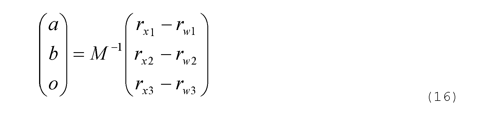
Auch kann der Beschleunigungssensor die Positionierung des Gerätes überwachen und im Falle einer durch diese detektierten Bewegung des Gerätes (Umpositionierung, Versatz, Anstossen, starkes Einsinken, Verlassen eines Nivellierbereichs, etc.) den Benutzer automatisch zu einer erneuten Nordung auffordern.Also, the acceleration sensor can monitor the positioning of the device and in case of detected by this movement of the device (repositioning, offset, abutment, strong sinking, leaving a leveling range, etc.) automatically prompt the user to a Nordung again.
Erfindungsgemäss kann anhand der bestimmten Daten auch ein Erwartungswert der erreichten Genauigkeit der Nordreferenzierung berechnet und dem Benutzer angezeigt werden, vorzugsweise als Azimutwinkelwert. Dieser lässt sich aus der erfindungsgemässen Mehrlagenmessung bestimmen.According to the invention, an expected value of the achieved accuracy of the north referencing can also be calculated on the basis of the determined data and displayed to the user, preferably as an azimuth angle value. This can be determined from the multilayer measurement according to the invention.
Erfindungsgemäss muss diese Horizontalebene jedoch nicht hochgenau mit der Drehebene zusammenfallen (was einer Abweichung der Lotrechten von der - die Drehung definierenden Stehachse gleichkommt). Es ist hinreichend die Neigung der Stehachse gegenüber der Lotrechten zu kennen, was eine jeweilige Beschleunigungsmessung in den zuvor beschriebenen drei Drehlagen gegeben ist. Diese kann bei den Berechnungen zur Nordreferenzierung entsprechend berücksichtigt werden.According to the invention, however, this horizontal plane does not have to coincide with high precision with the plane of rotation (which corresponds to a deviation of the perpendicular from the standing axis defining the rotation). It is sufficient to know the inclination of the standing axis with respect to the perpendicular, which is given a respective acceleration measurement in the three rotational positions described above. This can be taken into account in the calculations for Nordreferenzierung accordingly.
Claims (15)
dadurch gekennzeichnet, dass
auf dem Drehteil (3) ein Beschleunigungssensor (320) mit einer Messrichtung (22,32) orthogonal zur Messrichtung (21) des Gyroskops fixiert ist und
die Auswerteeinheit (4) derart ausgebildet ist, dass durch die Auswerteeinheit (4)
characterized in that
an acceleration sensor (320) having a measuring direction (22, 32) orthogonal to the measuring direction (21) of the gyroscope is fixed on the rotary part (3), and
the evaluation unit (4) is designed such that the evaluation unit (4)
dadurch gekennzeichnet, dass
die Auswerteeinheit (4) derart ausgebildet ist, dass durch diese anhand einer Benutzerführung durch manuelles Verdrehen des Drehteils (3) Drehlagen innerhalb der vorgegebenen
Drehlagenbereichen (36a,36b,36c) einnehmbar sind, insbesondere wobei die Drehlagenbereiche (36a,36b,36c) derart vorgegeben sind, dass der systematische Messfehler des Gyroskops (310) bestimmbar ist.Goniometer (1) according to claim 1,
characterized in that
the evaluation unit (4) is designed in such a way that by means of these, based on a user guidance, by means of manual rotation of the rotary part (3) rotational positions within the predetermined
Drehlagenbereichen (36a, 36b, 36c) are receivable, in particular wherein the rotational position areas (36a, 36b, 36c) are predetermined such that the systematic measurement error of the gyroscope (310) can be determined.
eine Anzieleinrichtung (10) montierbar ist welche gemeinsam mit dem Drehteil (3) des Goniometers (1) händisch drehbar ist, insbesondere wobei die Anzieleinrichtung (10) lediglich in einer vorgegebenen Drehlage auf dem Drehteil (3) montierbar ist.Goniometer (1) according to one of the preceding claims, characterized in that
a targeting device (10) can be mounted which is rotatable manually together with the rotary part (3) of the goniometer (1), in particular wherein the targeting device (10) can be mounted on the rotary part (3) only in a predetermined rotational position.
die Drehlagenbereiche (36a,36b,36c) zumindest annähernd äquidistant um die Stehachse (34) des Goniometers verteilt sind, insbesondere mit einem mittleren Winkelabstand von zumindest annähernd 120 Grad und einer Bereichsbreite von +/- 10 Grad, speziell von +/- 5 Grad.Goniometer (1) according to one of the preceding claims, characterized in that
the rotational position regions (36a, 36b, 36c) are distributed at least approximately equidistantly around the standing axis (34) of the goniometer, in particular with an average angular distance of at least approximately 120 degrees and an area width of +/- 10 degrees, especially +/- 5 degrees ,
die Auswerteeinheit (4) derart ausgebildet ist, dass in den zumindest drei Drehlagen anhand von Messwerten des Beschleunigungssensors eine Neigung der Stehachse (34) gegenüber einer Lotrechten (33) ermittelbar ist, welche bei der Bestimmung des Azimutwinkels des geographischen Nordpols einbezogen wird.Goniometer (1) according to one of the preceding claims, characterized in that
the evaluation unit (4) is designed such that in the at least three rotational positions based on measured values of the acceleration sensor, an inclination of the standing axis (34) relative to a vertical (33) can be determined, which is included in the determination of the azimuth angle of the geographic North Pole.
das Goniometer (1) in eine Anzieleinheit (10) oder in ein Stativ (11) integriert ist, wobei der Drehteil (3) mit der Anzieleinheit 10 oder die Basis (2) mit dem Stativ (11) fest verbunden ist.Goniometer (1) according to one of the preceding claims, characterized in that
the goniometer (1) is integrated in a target unit (10) or in a stand (11), the rotary part (3) being fixedly connected to the target unit 10 or the base (2) to the stand (11).
der Goniometer (1) mit einer Datenübertragungsschnittstelle ausgestattet ist, mittels welcher die Auswerteeinheit (4) die azimutale Ausrichtung mit externen Messwerten verknüpft, insbesondere wobei die externen Messwerte von einer montierten Anzieleinrichtung stammen.Goniometer (1) according to one of the preceding claims, characterized in that
the goniometer (1) is equipped with a data transmission interface, by means of which the evaluation unit (4) links the azimuthal orientation with external measured values, in particular wherein the external measured values originate from a mounted targeting device.
einen Neigungsmesser für
an inclinometer for
gekennzeichnet durch
marked by
gekennzeichnet durch
ein Bestimmen eines Erwartungswertes einer Genauigkeit des Bestimmen des Azimutwinkels (aG) des geographischen Nordpols (44) durch die Auswerteeinheit (4), insbesondere mit einem Bereitstellen des Erwartungswertes als Genauigkeitsschätzwert für einen Benutzer.Method according to one of claims 10 or 11,
marked by
determining an expectation value of an accuracy of the determination of the azimuth angle (aG) of the geographic North Pole (44) by the evaluation unit (4), in particular with the provision of the expected value as accuracy estimation value for a user.
gekennzeichnet durch
ein Erkennen einer Bewegung der Basis anhand von Messwerten eines Beschleunigungssensors durch die Auswerteeinheit und ausgeben einer Warnung bezüglich einer dadurch allfällig bedingten Invalidität des Azimutwinkels des geographischen Nordpols.Method according to one of claims 10 to 12,
marked by
detecting a movement of the base on the basis of measured values of an acceleration sensor by the evaluation unit and outputting a warning with respect to any disability of the azimuth angle of the geographic North Pole caused thereby .
gekennzeichnet durch
ein Bestimmen einer Neigung der Stehachse (34) gegenüber einer Lotrechten anhand einer Beschleunigungsmessung und Einbezug dieser Neigung in das Bestimmen des Azimutwinkels des geographischen Nordpols durch die Auswerteeinheit.Method according to one of claims 10 to 13,
marked by
determining an inclination of the standing axis (34) with respect to a perpendicular on the basis of an acceleration measurement and including this inclination in the determination of the azimuth angle of the geographic North Pole by the evaluation unit.
Priority Applications (3)
| Application Number | Priority Date | Filing Date | Title |
|---|---|---|---|
| EP11184180.5A EP2578992B1 (en) | 2011-10-06 | 2011-10-06 | Geographical azimuth determination referenced to north |
| US13/646,222 US8826550B2 (en) | 2011-10-06 | 2012-10-05 | Geographically north-referenced azimuth determination |
| IL222257A IL222257A (en) | 2011-10-06 | 2012-10-09 | Geographically north-referenced azimuth determination |
Applications Claiming Priority (1)
| Application Number | Priority Date | Filing Date | Title |
|---|---|---|---|
| EP11184180.5A EP2578992B1 (en) | 2011-10-06 | 2011-10-06 | Geographical azimuth determination referenced to north |
Publications (2)
| Publication Number | Publication Date |
|---|---|
| EP2578992A1 true EP2578992A1 (en) | 2013-04-10 |
| EP2578992B1 EP2578992B1 (en) | 2017-01-25 |
Family
ID=44720788
Family Applications (1)
| Application Number | Title | Priority Date | Filing Date |
|---|---|---|---|
| EP11184180.5A Active EP2578992B1 (en) | 2011-10-06 | 2011-10-06 | Geographical azimuth determination referenced to north |
Country Status (3)
| Country | Link |
|---|---|
| US (1) | US8826550B2 (en) |
| EP (1) | EP2578992B1 (en) |
| IL (1) | IL222257A (en) |
Cited By (6)
| Publication number | Priority date | Publication date | Assignee | Title |
|---|---|---|---|---|
| CN104006827A (en) * | 2014-06-09 | 2014-08-27 | 湖北三江航天红阳机电有限公司 | Method for evaluating stability of north orientation benchmark for inertial measurement unit calibration |
| DE102015017042A1 (en) | 2015-02-09 | 2016-08-11 | Dieter Schödlbauer | Arrangement and method for searching the northward geographical direction |
| CN105953820A (en) * | 2016-06-20 | 2016-09-21 | 浙江大学 | Optical calibration device for dynamic navigation performances of inertia measurement combination |
| CN104360380B (en) * | 2014-10-21 | 2017-02-15 | 中国人民解放军63653部队 | Geophysical characteristic based attitude correction method for deep-hole mounting of sensor |
| CN112325800A (en) * | 2020-09-22 | 2021-02-05 | 南京奂美光学科技有限公司 | Novel accurate angular instrument of photoelectric equipment |
| US11293754B2 (en) * | 2019-04-02 | 2022-04-05 | Topcon Corporation | Surveying instrument |
Families Citing this family (15)
| Publication number | Priority date | Publication date | Assignee | Title |
|---|---|---|---|---|
| FR2973108B1 (en) * | 2011-03-21 | 2019-06-28 | Safran Electronics & Defense | METHOD FOR UPDATING A NORTHERN ORIENTATION VALUE OR FOR IMPROVING THE INITIALIZATION OF SUCH VALUE IN AN APPARATUS COMPRISING AN IMAGE SENSOR |
| EP2578992B1 (en) * | 2011-10-06 | 2017-01-25 | Vectronix AG | Geographical azimuth determination referenced to north |
| CN103091662B (en) * | 2013-01-09 | 2015-08-05 | 上海大唐移动通信设备有限公司 | Localization method, drive test terminal and handheld terminal |
| US9418430B2 (en) * | 2013-10-03 | 2016-08-16 | Bae Systems Information And Electronic Systems Integration Inc. | Method and apparatus for establishing a north reference for inertial measurement units using scene correlation |
| EP2930466B1 (en) * | 2014-04-09 | 2018-07-18 | Safran Vectronix AG | Handheld observation device with a digital magnetic compass |
| EP3249353B1 (en) * | 2016-05-24 | 2021-09-08 | Safran Vectronix AG | Optoelectronic measuring device with magnetic compass and compensation functionality |
| EP3410063B1 (en) * | 2017-05-31 | 2020-10-14 | Leica Geosystems AG | Geodetic surveying with correction for instrument tilt |
| CN107340530A (en) * | 2017-09-05 | 2017-11-10 | 北京奥博泰科技有限公司 | A kind of split type GNSS geographical north orienting device based on RTK |
| RU185422U1 (en) * | 2018-06-20 | 2018-12-04 | Иван Владимирович Чернов | The device for determining the azimuth of direction and location |
| CN109029505A (en) * | 2018-09-21 | 2018-12-18 | 贵州航天计量测试技术研究所 | A kind of vehicle-mounted navigation attitude instrument north orientation orientation Initial Alignment Systems and alignment methods |
| CN110108276B (en) * | 2019-04-25 | 2022-09-13 | 长安大学 | Method for precisely measuring geographic latitude by using magnetic suspension gyroscope |
| CN112033384A (en) * | 2020-09-03 | 2020-12-04 | 珠海镭沃科技有限公司 | Laser demarcation device with angle detection function |
| RU2754964C1 (en) * | 2020-09-28 | 2021-09-08 | Акционерное общество "Всероссийский научно-исследовательский институт "Сигнал" | Azimuth determination method and dynamic gyrocompass |
| EP4237795A1 (en) * | 2020-10-30 | 2023-09-06 | Murata Manufacturing Co., Ltd. | Mems gyrocompass |
| CN114235004B (en) * | 2021-11-16 | 2023-08-08 | 华中光电技术研究所(中国船舶重工集团公司第七一七研究所) | Atomic gyroscope axial azimuth angle measuring device and method based on double theodolites |
Citations (6)
| Publication number | Priority date | Publication date | Assignee | Title |
|---|---|---|---|---|
| DE3141405A1 (en) * | 1981-10-19 | 1983-05-26 | Hellige Gmbh, 7800 Freiburg | METHOD FOR RAPID DETERMINATION OF AZIMUT ANGLE WITH THE AID OF A GYRO COMPASS |
| EP0250608A1 (en) | 1986-06-18 | 1988-01-07 | LITEF GmbH | Method and device for azimuth determination using a strap-down gyro |
| CA1269874A (en) | 1986-08-28 | 1990-06-05 | Raymond Bendett | Gyrocompassing apparatus for stationary equipment |
| US4945647A (en) | 1989-03-23 | 1990-08-07 | Allied-Signal Inc. | North finding system |
| EP0790485A2 (en) * | 1996-02-13 | 1997-08-20 | Bodenseewerk Gerätetechnik GmbH | Inertial sensor arrangement |
| EP2239540A1 (en) | 2009-04-07 | 2010-10-13 | Azimuth Technologies, Ltd. | Gyroscope adapted to be mounted to a goniometer |
Family Cites Families (5)
| Publication number | Priority date | Publication date | Assignee | Title |
|---|---|---|---|---|
| CH697492B1 (en) * | 2004-04-17 | 2008-11-14 | Vectronix Ag | A method for estimating the accuracy of azimuthal orientations, methods for providing azimuthal orientation of a portable target device and an estimated value of their accuracy and portable target device. |
| KR100620957B1 (en) * | 2004-12-13 | 2006-09-19 | 삼성전기주식회사 | Geomagnetic sensor for detecting azimuth and method thereof |
| US8099876B1 (en) * | 2008-11-21 | 2012-01-24 | The Boeing Company | Azimuth determination system and method therefor |
| EP2578992B1 (en) * | 2011-10-06 | 2017-01-25 | Vectronix AG | Geographical azimuth determination referenced to north |
| EP2578993B1 (en) * | 2011-10-06 | 2014-01-15 | Vectronix AG | Goniometer with graphical information reproduction means for producing information |
-
2011
- 2011-10-06 EP EP11184180.5A patent/EP2578992B1/en active Active
-
2012
- 2012-10-05 US US13/646,222 patent/US8826550B2/en active Active
- 2012-10-09 IL IL222257A patent/IL222257A/en active IP Right Grant
Patent Citations (6)
| Publication number | Priority date | Publication date | Assignee | Title |
|---|---|---|---|---|
| DE3141405A1 (en) * | 1981-10-19 | 1983-05-26 | Hellige Gmbh, 7800 Freiburg | METHOD FOR RAPID DETERMINATION OF AZIMUT ANGLE WITH THE AID OF A GYRO COMPASS |
| EP0250608A1 (en) | 1986-06-18 | 1988-01-07 | LITEF GmbH | Method and device for azimuth determination using a strap-down gyro |
| CA1269874A (en) | 1986-08-28 | 1990-06-05 | Raymond Bendett | Gyrocompassing apparatus for stationary equipment |
| US4945647A (en) | 1989-03-23 | 1990-08-07 | Allied-Signal Inc. | North finding system |
| EP0790485A2 (en) * | 1996-02-13 | 1997-08-20 | Bodenseewerk Gerätetechnik GmbH | Inertial sensor arrangement |
| EP2239540A1 (en) | 2009-04-07 | 2010-10-13 | Azimuth Technologies, Ltd. | Gyroscope adapted to be mounted to a goniometer |
Cited By (8)
| Publication number | Priority date | Publication date | Assignee | Title |
|---|---|---|---|---|
| CN104006827A (en) * | 2014-06-09 | 2014-08-27 | 湖北三江航天红阳机电有限公司 | Method for evaluating stability of north orientation benchmark for inertial measurement unit calibration |
| CN104006827B (en) * | 2014-06-09 | 2017-04-26 | 湖北三江航天红阳机电有限公司 | Method for evaluating stability of north orientation benchmark for inertial measurement unit calibration |
| CN104360380B (en) * | 2014-10-21 | 2017-02-15 | 中国人民解放军63653部队 | Geophysical characteristic based attitude correction method for deep-hole mounting of sensor |
| DE102015017042A1 (en) | 2015-02-09 | 2016-08-11 | Dieter Schödlbauer | Arrangement and method for searching the northward geographical direction |
| CN105953820A (en) * | 2016-06-20 | 2016-09-21 | 浙江大学 | Optical calibration device for dynamic navigation performances of inertia measurement combination |
| US11293754B2 (en) * | 2019-04-02 | 2022-04-05 | Topcon Corporation | Surveying instrument |
| CN112325800A (en) * | 2020-09-22 | 2021-02-05 | 南京奂美光学科技有限公司 | Novel accurate angular instrument of photoelectric equipment |
| CN112325800B (en) * | 2020-09-22 | 2022-04-12 | 南京奂美光学科技有限公司 | Precise angle measuring instrument for photoelectric equipment |
Also Published As
| Publication number | Publication date |
|---|---|
| IL222257A (en) | 2016-06-30 |
| EP2578992B1 (en) | 2017-01-25 |
| US8826550B2 (en) | 2014-09-09 |
| US20130192072A1 (en) | 2013-08-01 |
Similar Documents
| Publication | Publication Date | Title |
|---|---|---|
| EP2578992B1 (en) | Geographical azimuth determination referenced to north | |
| EP2824421B1 (en) | Digital Magnetic Compass Compensation | |
| DE69929525T2 (en) | METHOD AND DEVICE FOR GENERATING NAVIGATION DATA | |
| US9541392B2 (en) | Surveying system and method | |
| US8471906B2 (en) | Miniature celestial direction detection system | |
| DE4029215C2 (en) | ||
| RU2395061C1 (en) | Method to determine position of movable objects and integrated navigation system to this end | |
| DE102013015892B4 (en) | Position determination of a vehicle on or above a planetary surface | |
| CN108593965B (en) | A kind of accelerometer moored condition scaling method based on specific force mould and stable inertia | |
| EP2527792A1 (en) | Method for supporting a pilot when landing an aircraft in case of restricted visibility | |
| DE102014205640B4 (en) | Surveying using a mobile device | |
| EP2930466B1 (en) | Handheld observation device with a digital magnetic compass | |
| EP3249353B1 (en) | Optoelectronic measuring device with magnetic compass and compensation functionality | |
| EP2578993B1 (en) | Goniometer with graphical information reproduction means for producing information | |
| Hirt et al. | Expected accuracy of tilt measurements on a novel hexapod-based digital zenith camera system: a Monte-Carlo simulation study | |
| RU2308681C1 (en) | Gyroscopic navigation system for movable objects | |
| DE102006026561B3 (en) | North finder for a tunnel boring machine | |
| RU2315951C1 (en) | Onboard system for local aero-monitoring of objects of natural and technogenic sphere | |
| KR100623653B1 (en) | Mobile system for obtaining precise map data using differential global positioning system | |
| Cheng et al. | A novel method for target navigation and mapping based on laser ranging and MEMS/GPS navigation | |
| DE102020104911A1 (en) | Navigation system and method | |
| RU2552393C2 (en) | Device for off-center measurements | |
| Kai et al. | Research of polarization sensor and MEMS integrated navigation system technology | |
| JP2024060141A (en) | Surveying instruments and positioning systems | |
| DE10004017A1 (en) | Global autonomous determination method of meridian locations involves determining meridian of unknown location by changing known meridian congruent at specified angle in clockwise direction |
Legal Events
| Date | Code | Title | Description |
|---|---|---|---|
| PUAI | Public reference made under article 153(3) epc to a published international application that has entered the european phase |
Free format text: ORIGINAL CODE: 0009012 |
|
| AK | Designated contracting states |
Kind code of ref document: A1 Designated state(s): AL AT BE BG CH CY CZ DE DK EE ES FI FR GB GR HR HU IE IS IT LI LT LU LV MC MK MT NL NO PL PT RO RS SE SI SK SM TR |
|
| AX | Request for extension of the european patent |
Extension state: BA ME |
|
| 17P | Request for examination filed |
Effective date: 20130515 |
|
| 17Q | First examination report despatched |
Effective date: 20140403 |
|
| GRAJ | Information related to disapproval of communication of intention to grant by the applicant or resumption of examination proceedings by the epo deleted |
Free format text: ORIGINAL CODE: EPIDOSDIGR1 |
|
| GRAP | Despatch of communication of intention to grant a patent |
Free format text: ORIGINAL CODE: EPIDOSNIGR1 |
|
| GRAP | Despatch of communication of intention to grant a patent |
Free format text: ORIGINAL CODE: EPIDOSNIGR1 |
|
| INTG | Intention to grant announced |
Effective date: 20160830 |
|
| GRAS | Grant fee paid |
Free format text: ORIGINAL CODE: EPIDOSNIGR3 |
|
| GRAA | (expected) grant |
Free format text: ORIGINAL CODE: 0009210 |
|
| AK | Designated contracting states |
Kind code of ref document: B1 Designated state(s): AL AT BE BG CH CY CZ DE DK EE ES FI FR GB GR HR HU IE IS IT LI LT LU LV MC MK MT NL NO PL PT RO RS SE SI SK SM TR |
|
| REG | Reference to a national code |
Ref country code: GB Ref legal event code: FG4D Free format text: NOT ENGLISH |
|
| REG | Reference to a national code |
Ref country code: CH Ref legal event code: EP |
|
| REG | Reference to a national code |
Ref country code: AT Ref legal event code: REF Ref document number: 864400 Country of ref document: AT Kind code of ref document: T Effective date: 20170215 |
|
| REG | Reference to a national code |
Ref country code: IE Ref legal event code: FG4D Free format text: LANGUAGE OF EP DOCUMENT: GERMAN |
|
| REG | Reference to a national code |
Ref country code: DE Ref legal event code: R096 Ref document number: 502011011585 Country of ref document: DE |
|
| REG | Reference to a national code |
Ref country code: LT Ref legal event code: MG4D |
|
| REG | Reference to a national code |
Ref country code: NL Ref legal event code: MP Effective date: 20170125 |
|
| PG25 | Lapsed in a contracting state [announced via postgrant information from national office to epo] |
Ref country code: NL Free format text: LAPSE BECAUSE OF FAILURE TO SUBMIT A TRANSLATION OF THE DESCRIPTION OR TO PAY THE FEE WITHIN THE PRESCRIBED TIME-LIMIT Effective date: 20170125 |
|
| PG25 | Lapsed in a contracting state [announced via postgrant information from national office to epo] |
Ref country code: IS Free format text: LAPSE BECAUSE OF FAILURE TO SUBMIT A TRANSLATION OF THE DESCRIPTION OR TO PAY THE FEE WITHIN THE PRESCRIBED TIME-LIMIT Effective date: 20170525 Ref country code: NO Free format text: LAPSE BECAUSE OF FAILURE TO SUBMIT A TRANSLATION OF THE DESCRIPTION OR TO PAY THE FEE WITHIN THE PRESCRIBED TIME-LIMIT Effective date: 20170425 Ref country code: FI Free format text: LAPSE BECAUSE OF FAILURE TO SUBMIT A TRANSLATION OF THE DESCRIPTION OR TO PAY THE FEE WITHIN THE PRESCRIBED TIME-LIMIT Effective date: 20170125 Ref country code: GR Free format text: LAPSE BECAUSE OF FAILURE TO SUBMIT A TRANSLATION OF THE DESCRIPTION OR TO PAY THE FEE WITHIN THE PRESCRIBED TIME-LIMIT Effective date: 20170426 Ref country code: LT Free format text: LAPSE BECAUSE OF FAILURE TO SUBMIT A TRANSLATION OF THE DESCRIPTION OR TO PAY THE FEE WITHIN THE PRESCRIBED TIME-LIMIT Effective date: 20170125 Ref country code: HR Free format text: LAPSE BECAUSE OF FAILURE TO SUBMIT A TRANSLATION OF THE DESCRIPTION OR TO PAY THE FEE WITHIN THE PRESCRIBED TIME-LIMIT Effective date: 20170125 |
|
| PG25 | Lapsed in a contracting state [announced via postgrant information from national office to epo] |
Ref country code: RS Free format text: LAPSE BECAUSE OF FAILURE TO SUBMIT A TRANSLATION OF THE DESCRIPTION OR TO PAY THE FEE WITHIN THE PRESCRIBED TIME-LIMIT Effective date: 20170125 Ref country code: PT Free format text: LAPSE BECAUSE OF FAILURE TO SUBMIT A TRANSLATION OF THE DESCRIPTION OR TO PAY THE FEE WITHIN THE PRESCRIBED TIME-LIMIT Effective date: 20170525 Ref country code: ES Free format text: LAPSE BECAUSE OF FAILURE TO SUBMIT A TRANSLATION OF THE DESCRIPTION OR TO PAY THE FEE WITHIN THE PRESCRIBED TIME-LIMIT Effective date: 20170125 Ref country code: BG Free format text: LAPSE BECAUSE OF FAILURE TO SUBMIT A TRANSLATION OF THE DESCRIPTION OR TO PAY THE FEE WITHIN THE PRESCRIBED TIME-LIMIT Effective date: 20170425 Ref country code: SE Free format text: LAPSE BECAUSE OF FAILURE TO SUBMIT A TRANSLATION OF THE DESCRIPTION OR TO PAY THE FEE WITHIN THE PRESCRIBED TIME-LIMIT Effective date: 20170125 Ref country code: LV Free format text: LAPSE BECAUSE OF FAILURE TO SUBMIT A TRANSLATION OF THE DESCRIPTION OR TO PAY THE FEE WITHIN THE PRESCRIBED TIME-LIMIT Effective date: 20170125 Ref country code: PL Free format text: LAPSE BECAUSE OF FAILURE TO SUBMIT A TRANSLATION OF THE DESCRIPTION OR TO PAY THE FEE WITHIN THE PRESCRIBED TIME-LIMIT Effective date: 20170125 |
|
| REG | Reference to a national code |
Ref country code: FR Ref legal event code: PLFP Year of fee payment: 7 |
|
| REG | Reference to a national code |
Ref country code: DE Ref legal event code: R097 Ref document number: 502011011585 Country of ref document: DE |
|
| PG25 | Lapsed in a contracting state [announced via postgrant information from national office to epo] |
Ref country code: CZ Free format text: LAPSE BECAUSE OF FAILURE TO SUBMIT A TRANSLATION OF THE DESCRIPTION OR TO PAY THE FEE WITHIN THE PRESCRIBED TIME-LIMIT Effective date: 20170125 Ref country code: IT Free format text: LAPSE BECAUSE OF FAILURE TO SUBMIT A TRANSLATION OF THE DESCRIPTION OR TO PAY THE FEE WITHIN THE PRESCRIBED TIME-LIMIT Effective date: 20170125 Ref country code: EE Free format text: LAPSE BECAUSE OF FAILURE TO SUBMIT A TRANSLATION OF THE DESCRIPTION OR TO PAY THE FEE WITHIN THE PRESCRIBED TIME-LIMIT Effective date: 20170125 Ref country code: RO Free format text: LAPSE BECAUSE OF FAILURE TO SUBMIT A TRANSLATION OF THE DESCRIPTION OR TO PAY THE FEE WITHIN THE PRESCRIBED TIME-LIMIT Effective date: 20170125 Ref country code: SK Free format text: LAPSE BECAUSE OF FAILURE TO SUBMIT A TRANSLATION OF THE DESCRIPTION OR TO PAY THE FEE WITHIN THE PRESCRIBED TIME-LIMIT Effective date: 20170125 |
|
| PG25 | Lapsed in a contracting state [announced via postgrant information from national office to epo] |
Ref country code: DK Free format text: LAPSE BECAUSE OF FAILURE TO SUBMIT A TRANSLATION OF THE DESCRIPTION OR TO PAY THE FEE WITHIN THE PRESCRIBED TIME-LIMIT Effective date: 20170125 Ref country code: SM Free format text: LAPSE BECAUSE OF FAILURE TO SUBMIT A TRANSLATION OF THE DESCRIPTION OR TO PAY THE FEE WITHIN THE PRESCRIBED TIME-LIMIT Effective date: 20170125 |
|
| PLBE | No opposition filed within time limit |
Free format text: ORIGINAL CODE: 0009261 |
|
| STAA | Information on the status of an ep patent application or granted ep patent |
Free format text: STATUS: NO OPPOSITION FILED WITHIN TIME LIMIT |
|
| 26N | No opposition filed |
Effective date: 20171026 |
|
| PG25 | Lapsed in a contracting state [announced via postgrant information from national office to epo] |
Ref country code: SI Free format text: LAPSE BECAUSE OF FAILURE TO SUBMIT A TRANSLATION OF THE DESCRIPTION OR TO PAY THE FEE WITHIN THE PRESCRIBED TIME-LIMIT Effective date: 20170125 |
|
| PG25 | Lapsed in a contracting state [announced via postgrant information from national office to epo] |
Ref country code: MC Free format text: LAPSE BECAUSE OF FAILURE TO SUBMIT A TRANSLATION OF THE DESCRIPTION OR TO PAY THE FEE WITHIN THE PRESCRIBED TIME-LIMIT Effective date: 20170125 |
|
| REG | Reference to a national code |
Ref country code: IE Ref legal event code: MM4A |
|
| PG25 | Lapsed in a contracting state [announced via postgrant information from national office to epo] |
Ref country code: LU Free format text: LAPSE BECAUSE OF NON-PAYMENT OF DUE FEES Effective date: 20171006 |
|
| REG | Reference to a national code |
Ref country code: BE Ref legal event code: MM Effective date: 20171031 |
|
| PG25 | Lapsed in a contracting state [announced via postgrant information from national office to epo] |
Ref country code: BE Free format text: LAPSE BECAUSE OF NON-PAYMENT OF DUE FEES Effective date: 20171031 |
|
| PG25 | Lapsed in a contracting state [announced via postgrant information from national office to epo] |
Ref country code: MT Free format text: LAPSE BECAUSE OF FAILURE TO SUBMIT A TRANSLATION OF THE DESCRIPTION OR TO PAY THE FEE WITHIN THE PRESCRIBED TIME-LIMIT Effective date: 20170125 |
|
| REG | Reference to a national code |
Ref country code: FR Ref legal event code: PLFP Year of fee payment: 8 |
|
| PG25 | Lapsed in a contracting state [announced via postgrant information from national office to epo] |
Ref country code: IE Free format text: LAPSE BECAUSE OF NON-PAYMENT OF DUE FEES Effective date: 20171006 |
|
| REG | Reference to a national code |
Ref country code: AT Ref legal event code: MM01 Ref document number: 864400 Country of ref document: AT Kind code of ref document: T Effective date: 20171006 |
|
| PG25 | Lapsed in a contracting state [announced via postgrant information from national office to epo] |
Ref country code: AT Free format text: LAPSE BECAUSE OF NON-PAYMENT OF DUE FEES Effective date: 20171006 |
|
| PG25 | Lapsed in a contracting state [announced via postgrant information from national office to epo] |
Ref country code: HU Free format text: LAPSE BECAUSE OF FAILURE TO SUBMIT A TRANSLATION OF THE DESCRIPTION OR TO PAY THE FEE WITHIN THE PRESCRIBED TIME-LIMIT; INVALID AB INITIO Effective date: 20111006 |
|
| PG25 | Lapsed in a contracting state [announced via postgrant information from national office to epo] |
Ref country code: CY Free format text: LAPSE BECAUSE OF NON-PAYMENT OF DUE FEES Effective date: 20170125 |
|
| PG25 | Lapsed in a contracting state [announced via postgrant information from national office to epo] |
Ref country code: MK Free format text: LAPSE BECAUSE OF FAILURE TO SUBMIT A TRANSLATION OF THE DESCRIPTION OR TO PAY THE FEE WITHIN THE PRESCRIBED TIME-LIMIT Effective date: 20170125 |
|
| PG25 | Lapsed in a contracting state [announced via postgrant information from national office to epo] |
Ref country code: TR Free format text: LAPSE BECAUSE OF FAILURE TO SUBMIT A TRANSLATION OF THE DESCRIPTION OR TO PAY THE FEE WITHIN THE PRESCRIBED TIME-LIMIT Effective date: 20170125 |
|
| PG25 | Lapsed in a contracting state [announced via postgrant information from national office to epo] |
Ref country code: AL Free format text: LAPSE BECAUSE OF FAILURE TO SUBMIT A TRANSLATION OF THE DESCRIPTION OR TO PAY THE FEE WITHIN THE PRESCRIBED TIME-LIMIT Effective date: 20170125 |
|
| PGFP | Annual fee paid to national office [announced via postgrant information from national office to epo] |
Ref country code: GB Payment date: 20230920 Year of fee payment: 13 |
|
| PGFP | Annual fee paid to national office [announced via postgrant information from national office to epo] |
Ref country code: FR Payment date: 20230920 Year of fee payment: 13 |
|
| PGFP | Annual fee paid to national office [announced via postgrant information from national office to epo] |
Ref country code: DE Payment date: 20230920 Year of fee payment: 13 Ref country code: CH Payment date: 20231101 Year of fee payment: 13 |