EP2578942A2 - Apparatus for head end direct air injection with enhanced mixing capabaliites - Google Patents
Apparatus for head end direct air injection with enhanced mixing capabaliites Download PDFInfo
- Publication number
- EP2578942A2 EP2578942A2 EP12187049.7A EP12187049A EP2578942A2 EP 2578942 A2 EP2578942 A2 EP 2578942A2 EP 12187049 A EP12187049 A EP 12187049A EP 2578942 A2 EP2578942 A2 EP 2578942A2
- Authority
- EP
- European Patent Office
- Prior art keywords
- combustor
- fuel
- stream
- exhaust
- air
- Prior art date
- Legal status (The legal status is an assumption and is not a legal conclusion. Google has not performed a legal analysis and makes no representation as to the accuracy of the status listed.)
- Withdrawn
Links
Images


Classifications
-
- F—MECHANICAL ENGINEERING; LIGHTING; HEATING; WEAPONS; BLASTING
- F23—COMBUSTION APPARATUS; COMBUSTION PROCESSES
- F23R—GENERATING COMBUSTION PRODUCTS OF HIGH PRESSURE OR HIGH VELOCITY, e.g. GAS-TURBINE COMBUSTION CHAMBERS
- F23R3/00—Continuous combustion chambers using liquid or gaseous fuel
- F23R3/28—Continuous combustion chambers using liquid or gaseous fuel characterised by the fuel supply
-
- F—MECHANICAL ENGINEERING; LIGHTING; HEATING; WEAPONS; BLASTING
- F23—COMBUSTION APPARATUS; COMBUSTION PROCESSES
- F23C—METHODS OR APPARATUS FOR COMBUSTION USING FLUID FUEL OR SOLID FUEL SUSPENDED IN A CARRIER GAS OR AIR
- F23C9/00—Combustion apparatus characterised by arrangements for returning combustion products or flue gases to the combustion chamber
-
- F—MECHANICAL ENGINEERING; LIGHTING; HEATING; WEAPONS; BLASTING
- F23—COMBUSTION APPARATUS; COMBUSTION PROCESSES
- F23R—GENERATING COMBUSTION PRODUCTS OF HIGH PRESSURE OR HIGH VELOCITY, e.g. GAS-TURBINE COMBUSTION CHAMBERS
- F23R3/00—Continuous combustion chambers using liquid or gaseous fuel
- F23R3/02—Continuous combustion chambers using liquid or gaseous fuel characterised by the air-flow or gas-flow configuration
- F23R3/04—Air inlet arrangements
- F23R3/10—Air inlet arrangements for primary air
-
- F—MECHANICAL ENGINEERING; LIGHTING; HEATING; WEAPONS; BLASTING
- F23—COMBUSTION APPARATUS; COMBUSTION PROCESSES
- F23C—METHODS OR APPARATUS FOR COMBUSTION USING FLUID FUEL OR SOLID FUEL SUSPENDED IN A CARRIER GAS OR AIR
- F23C2202/00—Fluegas recirculation
- F23C2202/30—Premixing fluegas with combustion air
-
- F—MECHANICAL ENGINEERING; LIGHTING; HEATING; WEAPONS; BLASTING
- F23—COMBUSTION APPARATUS; COMBUSTION PROCESSES
- F23C—METHODS OR APPARATUS FOR COMBUSTION USING FLUID FUEL OR SOLID FUEL SUSPENDED IN A CARRIER GAS OR AIR
- F23C2202/00—Fluegas recirculation
- F23C2202/50—Control of recirculation rate
Definitions
- the present invention relates to a combustion system for gas turbine engines and, more particularly, to an improved combustor design and method for using direct air injection and a substantially inert gas feed such as an exhaust gas recycle stream (“EGR”) as the primary working fluid.
- EGR exhaust gas recycle stream
- the method and apparatus according to the invention reduce the formation of undesirable gas emissions from the gas turbine engine while increasing the overall efficiency of the combustor.
- Gas turbine engines typically include a compressor section, a combustor section and a turbine that rotates to generate electrical power.
- the compressor discharges higher pressure gas directly into the combustor where hydrocarbon fuel is injected, mixed and burned to produce thermal and kinetic energy.
- the combustion gases are then channeled into and through one or more stages of the turbine which extracts rotational energy from the exhaust gases with the rotational energy then being used to generate electrical power.
- Most existing gas turbine engines include multiple combustors positioned circumferentially around a rotational axis. In order to achieve maximum operating efficiency, the combustors operate over a wide range of different fuel compositions, pressures, temperatures and fuel/air ratios, preferably with the ability to use either liquid or gas fuels.
- the combustion exhaust invariably contains small amounts of excess CO and oxygen, with some CO 2 disassociating into CO and O 2 , depending on the specific combustor operating conditions. Unless removed, the same components, including the residual amount of oxygen, remain in the system as they pass into and through components downstream of the combustor, e.g., the turbine and heat recovery steam generator.
- the final exhaust stream from conventional gas turbine engines includes N 2 and CO 2 with small amounts of CO, O 2 and oxides of nitrogen, all of which eventually must be removed or reacted in downstream operations (such as by catalyst treatment) in order to maintain desired gas turbine efficiencies.
- the need for combustors with improved emissions is a direct outgrowth of air pollution concerns resulting from more stringent domestic and international pollution control standards such as those promulgated by the Environmental Protection Agency regulating the release of oxides of nitrogen, unburned hydrocarbons and carbon monoxide.
- the unwanted emissions generally fall into two broad categories -- those resulting from high flame temperatures (e.g., NO x ) and those formed at lower flame temperatures, such as CO, that do not allow the basic fuel-air reaction to proceed to completion.
- NO x high flame temperatures
- CO lower flame temperatures
- Operating at low combustion temperatures in order to lower the NO X emissions can result in incomplete or partially incomplete combustion, which in turn leads to the production of excessive amounts of unburned hydrocarbons and carbon monoxide, as well as lower power output and lower thermal efficiency of the engine.
- Higher combustion temperatures tend to improve thermal efficiency and lower the amount of unburned hydrocarbons and CO, but can still result in a higher amount of NO X if the combustion mixture and operating conditions are not properly monitored and controlled.
- the present invention addresses the above concerns by providing a new method for reducing and controlling the CO and oxygen emissions in a gas turbine combustor using a hydrocarbon fuel that is burned with an oxidizer such as air or "oxyfuel.”
- the invention includes the use of a significant volume of a low to near zero oxygen content gas, such as the exhaust gas recycle ("EGR") from the gas turbine engine as a major part of the working fluid.
- EGR exhaust gas recycle
- the use of an inert combustor feed offers particular advantages for applications in which the gas turbine system is designed to achieve stoichiometric exhaust gas recirculation in order to reach target emissions goals.
- combustion dynamics can be significantly improved by changing the nature and composition of the primary working fluid and the manner in which it is fed to the combustor head end prior to ignition, resulting in improved emissions (less oxygen and CO formed during combustion) without sacrificing engine efficiency.
- the invention described below includes a new method for reducing the amount of carbon monoxide and oxygen emissions in a hydrocarbon combustor in a gas turbine engine using the following basic steps: feeding hydrocarbon fuel and an oxidizer component (such as air) directly into the head end of the combustor while injecting defined amounts of a substantially inert gas (nominally an exhaust gas recycle or "EGR") directly into the combustor head with the fuel and oxidizer; igniting the fuel mixture to form a combustor exhaust stream that includes EGR; cooling the combustor exhaust using a portion of the same EGR circulated around the combustor shell and then exhausted from the system; detecting the amount of carbon monoxide and oxygen present in the combustor exhaust; and adjusting the amount of fuel, oxidizer and inert gas feeds based on the detected amount of carbon monoxide and oxygen.
- a substantially inert gas nominally an exhaust gas recycle or "EGR”
- the invention can be incorporated into a gas turbine engine comprising a gas compressor, one or more combustors as described above, a turbine driven by the expanded exhaust from the combustors, a primary fuel circuit for the combustors that feeds hydrocarbon fuel and air to each combustor, means for feeding the substantially inert gas stream into each combustor, carbon monoxide and oxygen sensors disposed in the exhaust stream, and a control for determining the amount of fuel, air and substantially inert gas stream to be fed to each combustor based on the detected amount of carbon monoxide and oxygen.
- the invention thus includes both a method and combustor architecture that uses direct air injection into the head end of the combustor in combination with an inert feed, namely a very low oxygen-content gas recycle stream as the working fluid.
- both the external air and a portion of the gas turbine exhaust (having little or no oxygen present and reduced in temperature) are combined to form the primary working fluid after the combustor reaches a desired level of operation following startup.
- the lower temperature inert gas stream (comprising mostly nitrogen and CO 2 ) serves to improve the stoichiometry of the combustion while acting as a cooling medium for the combustor itself.
- the method as described below in connection with Figures 1-6 includes two principal modes of operation: (a) the use of a primary working fluid comprising air and an inert exhaust gas recycle stream in an amount up to about 50% by volume of the total feed to the combustor, with the EGR stream being supplied to the combustor from a gas turbine compressor; and (b) the use of the same substantially inert gas (EGR) as a coolant for the hot section of the combustor and to help control the combustor flame temperature.
- a primary working fluid comprising air and an inert exhaust gas recycle stream in an amount up to about 50% by volume of the total feed to the combustor, with the EGR stream being supplied to the combustor from a gas turbine compressor
- EGR substantially inert gas
- the new combustor design and related method are capable of supporting stoichiometric combustion with minimum resulting O 2 and CO emissions.
- the amount of NO X and CO emissions can also be adjusted by an additional diluent injection (such as nitrogen) directly into the combustor head end.
- additional diluent injection such as nitrogen
- the combustor nozzle designs described below for use with the head end result in improved mixing of the fuel, air and EGR before the mixture is injected into the combustor.
- the invention also includes an integrated fuel and air combustion system for a gas turbine engine comprising one or more combustors, a modified fuel supply for providing hydrocarbon fuel to the combustors, a compressed external air supply for the combustor (such as that generated by a main air compressor), means for providing the inert exhaust gas recycle stream to the combustor and a modified fuel and air nozzle positioned in the head end of the combustor for providing the desired mixing of components prior to ignition.
- a gas turbine engine comprising one or more combustors, a modified fuel supply for providing hydrocarbon fuel to the combustors, a compressed external air supply for the combustor (such as that generated by a main air compressor), means for providing the inert exhaust gas recycle stream to the combustor and a modified fuel and air nozzle positioned in the head end of the combustor for providing the desired mixing of components prior to ignition.
- the present invention includes means for injecting air directly into the combustor head end along with a significant volume of an inert gas into the combustor at particular specified locations along the exhaust flow path in order to reduce unwanted emissions, particularly CO and oxygen, while improving overall combustor performance.
- An exemplary system uses a specified amount of exhaust gas recycle (which is substantially inert and at a lower temperature after passing through the turbine) in an amount up to about 50% of the total combustor feed, with the remaining 50% comprising about 5% hydrocarbon fuel and 45% air.
- the use of an inert gas as part of the working fluid also serves to cool the combustor and reduce the combustor flame temperature while improving the stoichiometry of the gas combustion.
- the inert gas feed helps to establish an equivalence ratio approaching 1.0 for the fuel and oxygen fed to the combustor.
- Minimizing the final oxygen content in the combustor exhaust also reduces potential metallurgical damage resulting from the presence of residual oxygen in the system.
- a major component of the combustor feed is taken directly from a lower temperature gas turbine exhaust stream that is recycled back to a gas turbine compressor (but with water removed).
- the EGR stream passes into and out of the combustor in two different ways - first, as a feed stream into the combustor by passing the EGR through a plurality of small apertures in an exterior sleeve surrounding the combustor core; second, as a cooling medium within the same sleeve flowing in a direction opposite the core flow.
- the cooling EGR gas is then exhausted from the combustor through an outlet in the combustor shell.
- the total volume of substantially inert gas being used is approximately the same as the amount of external air entering the head end of the combustor.
- FIGURES 1-6 illustrate a number of key aspects of the invention. First, they show the injection of inert gas directly into the combustor beginning near the combustor flame and ending at a point downstream of the flame. Second, they depict the countercurrent flow of the EGR in order to cool the combustor exhaust (and shell) and to help lower the flame temperature. Third, they show how the remainder of the inert gas stream is exhausted from the combustor near the head end. Finally, they illustrate the means for efficiently mixing the air, exhaust gas recycle and fuel feeds through injection nozzles specially adapted and configured to accommodate the new flow patterns as described in more detail below (see FIGURES 4 and 5 ).
- an inert gas stream containing very little oxygen (approximately 5% of the total feed) is fed to the combustor during start-up, with the amount and volume of EGR increasing as the combustor reaches steady state operating conditions.
- the amount of inert gas fed to the head end of the combustor thus gradually increases over time (up to about 50%) based on the detected amount of CO and oxygen in the exhaust stream (hopefully approaching zero as the combustor continues to operate).
- the invention thereby achieves three benefits over conventional combustor designs: (1) lowers the residual oxygen content in the combustor exhaust to a near zero stoichiometric level; (2) helps control the composition and temperature of the combustor emissions; and (3) assists in lowering and controlling the combustor flame temperature.
- the low oxygen content of the final exhaust gas also helps to prevent uneven combustion (such as combustion occurring at or near the combustor wall). Further, since the cooling gases being recycled into the head end of the combustor are substantially inert, the risk of forming unwanted CO from CO 2 is much lower because less oxygen is present in the system.
- Figures 1-6 also illustrate two exemplary nozzle configurations used to uniformly mix and distribute the air, fuel and substantially inert gas flow into the combustor, both of which allow for a maximum flow volume of air but with a low pressure drop into the nozzle upstream of the ignition point. It should be noted that the nozzle configurations shown in the figures may be adopted for use with multiple combustors having slightly different operating characteristics, fuel feeds and performance criteria.
- Each combustor also normally includes multiple fuel nozzles, each of which has a dedicated premixing section so that fuel is premixed with air prior to ignition in the combustion chamber.
- multiple dedicated premixing sections allow for the thorough premixing of fuel and air prior to being burned, a feature that assists in achieving low NO x , CO and O 2 levels.
- the plurality of diffusion/premix fuel nozzles are arranged in a circular array about the longitudinal axis of a cylindrical combustor casing, with the nozzles mounted within the combustor end cover assembly at the head end.
- the fuel nozzles extend into a combustor shroud with a central fuel injection port that premixes the combustion air with injected fuel as described below. See FIGURES 2-4 .
- the figures also illustrate the use of a cylindrical flow sleeve integral with and concentrically aligned with the cylindrical combustor shell.
- the flow sleeve is formed from an interior combustion liner coupled to the end cap assembly.
- a flow passage is defined between the liner and outside wall of the flow sleeve.
- the interior wall of the flow passage includes a plurality of apertures which enable the inert gas to flow through the passages directly into the combustor chamber at locations beginning at the head end opposite the tip of the combustor flame and extending down into the combustor chamber to a point where the gases are fully combusted.
- the inert EGR gas flows in a direction generally opposite the direction of core flow through the combustor nozzles, i.e., towards rather than away from, the end cover assembly.
- a fixed volume of another diluent such as nitrogen
- the diluent can be introduced near the periphery of the fuel nozzle where it mixes with the air and fuel immediately upstream of the fuel nozzle.
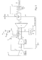
- FIGURE 1 is a process flow diagram of an exemplary gas turbine engine system illustrating the basic components and process steps for carrying out the method according to the invention as summarized above.
- Controlled air feed 1 passes into a main air compressor 2 and exists at elevated pressure from the last stage of the compressor as shown at compressor exit stream 5 into combustor 6.
- the main air compressor and gas turbine compressor 4 are operatively connected via rotating shaft 3 as shown.
- Gas turbine compressor 4 operates to drive gas turbine 8 via rotating shaft 9.
- the higher pressure compressor exit stream 5 leaving main air compressor 2 feeds directly into combustor 6 with the flow rate controlled using control valve 11.
- a controlled amount of hydrocarbon fuel 29 (such as natural gas) also feeds directly into combustor 6 through control valve 26 where it ignites and produces thermal and kinetic energy.
- the spent exhaust gasses 7 exiting from the combustor drive gas turbine 8 and then pass at a lower pressure as shown at gas turbine exhaust line 14 into heat recovery steam generator ("HRSG") 15.
- HRSG heat recovery steam generator
- the exhaust gas recirculation ("EGR") loop 16 which comprises an inert mixture of nitrogen, CO, CO 2 and only residual amounts of oxygen, is recycled as shown back to gas turbine compressor 4 and thereafter fed at higher pressure directly into combustor 6 as shown by gas turbine feed 10.
- EGR exhaust gas recirculation
- Exhaust stream 20 from HRSG 15 is used to drive steam turbine 19 to generate electrical power via generator 22 in a conventional manner.
- HRSG valve 12 typically, a portion of the spent exhaust from HRSG 15 will be removed from the HRSG through HRSG valve 12 and vented to the atmosphere as shown through vent line 18.
- the spent exhaust gasses leaving the last stage of steam turbine 19 are recycled back to the HRSG 15 via HRSG recycle line 21.
- substantially inert gas stream 16 (typically EGR), which is now reduced in temperature after leaving HRSG 15 and has water removed as shown at water discharge line 17, becomes part of the main feed into combustor 6 (see FIGURES 2 through 4 ).
- EGR recycles back to gas turbine compressor 4 and then feeds at higher pressure directly into combustor 6 as described above, with the flow rate being monitored and controlled.
- the flow rate of fuel to the combustor can be adjusted by control valve 26.
- FIG. 1 also illustrates how the gas turbine exhaust will be treated (if necessary) to remove any final residual carbon monoxide and oxygen in the system. If the combustion step is not stoichiometrically perfect, a small amount of unburned oxygen and CO may still need to be treated in a separate operation.
- a portion of the combustor exhaust stream 25 passes through an oxygen and hydrogen scrubber 23 which removes CO and consumes unburned free oxygen to form carbon dioxide stream 24.
- the CO scrubbing operation may comprise a catalyst bed that converts CO to carbon dioxide and consumes oxygen in an exothermic reaction.
- the gas turbine exhaust also passes through HRSG 15 which uses the intrinsic heat value of the exhaust gas to generate steam and extract energy via the steam turbine.
- FIGURE 1 also depicts the potential use of an additional diluent stream (shown in dotted line format) comprising nitrogen as part of the feed to the combustor head end, depending on the specific operating conditions of the combustor and need to further reduce the oxygen content of the combustor exhaust.
- Additional nitrogen diluent 27 can be introduced into the combustor as shown after passing through motor valve 28 which adjusts the flow as needed.
- FIGURE 2 is a cross-section of an exemplary embodiment of a combustor design in accordance with the invention showing means for injecting a mixture of air, a substantially inert exhaust gas stream (EGR) and hydrocarbon fuel to form the primary working fluid for the combustor, with a portion of the substantially inert gas stream also serving as a cooling medium for the combustor.
- the feed to combustor 30 includes air being fed directly into the combustor head end 34 as shown by air feed 31 as shown (rather than pre-mixed with fuel upstream of the combustor inlet), with a small amount of inert gas (EGR) being introduced as described above through the plurality of flow apertures 36 in the combustor shell.
- the inert exhaust gas recycle stream can gradually be increased by injection into the combustor core using cylindrical flow sleeve 37 which is concentrically aligned with the combustor casing.
- Flow sleeve 37 includes an interior combustion liner 38 coupled to the end cap assembly which, together with the combustor exterior shell, form an EGR flow passage.
- the interior wall of flow sleeve 37 includes a plurality of flow apertures 36 which enable the compressed EGR gas from the gas turbine compressor (item 4 in FIGURE 1 ) to enter and pass through the apertures directly into the combustor chamber, extending from a point opposite the combustor flame to a point generally downstream of the combustion at 39.
- the direction of flow inside flow sleeve 37 is opposite the direction of core flow through the combustor nozzles as described above, i.e., toward rather than away from the end cover assembly. (See flow direction arrow 33).
- the substantially inert gas performs three functions in the embodiment of FIGURE 2 , namely injecting inert gas directly into the combustor through the plurality of flow apertures 36; providing cooling to the lower combustor chamber, particular near the combustor wall; and helping to lower the combustor flame temperature.
- the portion of substantially inert gas flowing through flow sleeve 37 i.e., the gas that does not pass into the combustor core via flow apertures, is exhausted from the combustor through EGR exhaust port 35.
- FIGURE 3 is a cross-sectional view of the head end of a combustor design according to the invention depicting in greater detail the configuration and flow pattern for the air, fuel and substantially inert gas feeds into the combustor nozzle.
- Each fuel nozzle 50 includes at least one gas flow chamber 51 and one fuel chamber 52.
- the combined air and exhaust gas pass from gas flow chamber 51 through a plurality of injection openings 54 extending through the nozzle tip into a downstream mixing chamber (see also FIGURE 5 ).
- the fuel flow from fuel chamber 52 passes through a plurality of fuel holes 56 extending through the nozzle tip into a mixing chamber.
- a plurality of gas swirler holes 57 extend through the nozzle from the outer surface of the fuel nozzle to the tip.
- a separate diluent feed line typically cylindrical, may also be included which extends around the perimeter of fuel nozzle 50 with additional flow passages sized to permit a secondary diluent flow to be included in the combined feed to the nozzle.
- a shroud guides the additional diluent flow toward the plurality of holes thus ensuring that a portion flow passes through the air swirler holes and into the mixing chamber where it mixes with the exhaust gas, air and fuel.
- FIGURE 4 The cross-sectional view of FIGURE 4 , shown partially in perspective, illustrates an exemplary mixing head 60 and means for injecting air, fuel and optionally a portion of the substantially inert gas directly into the combustor.
- the fuel injected into the combustor passes through fuel passage 61 into a mixing zone defined by shroud 55 and combines with air passing into air manifold 62 and through the plurality of air passages as shown by way of example as gas swirler holes 57.
- the embodiment of FIGURE 4 thus ensures that air and fuel (and possibly some additional diluent) are thoroughly mixed prior to entering the combustor upstream of the ignition point.
- the use of direct air injection requires that the nozzles be capable of handling a significantly increased air flow as compared to conventional combustor nozzle designs.
- FIGURE 5 is a further exemplary mixing head assembly 70 for use in injecting air, exhaust gas and/or substantially inert gas into the combustor in accordance with the invention.
- the fuel to be injected into the combustor passes through fuel passage 71 into a fuel mixing zone defined by shroud 74 and then mixes with air passing into air manifold 72 through a plurality of vein-like air passages 73.
- the embodiment of FIGURE 5 ensures that air and fuel (and possibly diluent) are thoroughly mixed prior to entering the combustor upstream of the ignition point.
- FIGURE 6 includes two comparative block flow diagrams illustrating the basic modes of operation of the method according to the invention as described above, namely the use of an inert gas flows to the combustor during start-up and shut down as compared to such use during a stoichiometric mode of operation.
- EGR substantially inert gas
Landscapes
- Engineering & Computer Science (AREA)
- Chemical & Material Sciences (AREA)
- Combustion & Propulsion (AREA)
- Mechanical Engineering (AREA)
- General Engineering & Computer Science (AREA)
Abstract
A method for reducing the amount of carbon monoxide and oxygen emissions in a hydrocarbon combustor (6) in a gas turbine engine by feeding hydrocarbon fuel (29) and an oxidizer component (1) into the head end of the combustor (6) while also injecting substantially inert gas (16) into the combustor (6) with the fuel (29) and oxidizer (1); forming a combustor exhaust stream (25) that mixes with the recycle (16); cooling the combustor exhaust (25); detecting the amount of carbon monoxide and oxygen in the exhaust and adjusting the amount of fuel (29), oxidizer (1) and inert gas (16) feeds based on the detected amounts.
Description
- The present invention relates to a combustion system for gas turbine engines and, more particularly, to an improved combustor design and method for using direct air injection and a substantially inert gas feed such as an exhaust gas recycle stream ("EGR") as the primary working fluid. (The terms "inert gas stream" and "substantially inert gas stream" are used interchangeably herein to refer to an EGR type gas stream having small, residual amounts of oxygen). The method and apparatus according to the invention reduce the formation of undesirable gas emissions from the gas turbine engine while increasing the overall efficiency of the combustor.
- Gas turbine engines typically include a compressor section, a combustor section and a turbine that rotates to generate electrical power. The compressor discharges higher pressure gas directly into the combustor where hydrocarbon fuel is injected, mixed and burned to produce thermal and kinetic energy. The combustion gases are then channeled into and through one or more stages of the turbine which extracts rotational energy from the exhaust gases with the rotational energy then being used to generate electrical power. Most existing gas turbine engines include multiple combustors positioned circumferentially around a rotational axis. In order to achieve maximum operating efficiency, the combustors operate over a wide range of different fuel compositions, pressures, temperatures and fuel/air ratios, preferably with the ability to use either liquid or gas fuels. Most gas turbine engines also tend to operate in a slightly "rich" mode, i.e., with less than the precise stoichiometric amount of oxygen in the feed necessary to bum the entire hydrocarbon fuel mixture, resulting in at least some incomplete combustion, and hence the production of carbon monoxide and other by-products.
- In most systems, the combustion exhaust invariably contains small amounts of excess CO and oxygen, with some CO2 disassociating into CO and O2, depending on the specific combustor operating conditions. Unless removed, the same components, including the residual amount of oxygen, remain in the system as they pass into and through components downstream of the combustor, e.g., the turbine and heat recovery steam generator. As a result, the final exhaust stream from conventional gas turbine engines includes N2 and CO2 with small amounts of CO, O2 and oxides of nitrogen, all of which eventually must be removed or reacted in downstream operations (such as by catalyst treatment) in order to maintain desired gas turbine efficiencies.
- The need for combustors with improved emissions is a direct outgrowth of air pollution concerns resulting from more stringent domestic and international pollution control standards such as those promulgated by the Environmental Protection Agency regulating the release of oxides of nitrogen, unburned hydrocarbons and carbon monoxide. The unwanted emissions generally fall into two broad categories -- those resulting from high flame temperatures (e.g., NOx) and those formed at lower flame temperatures, such as CO, that do not allow the basic fuel-air reaction to proceed to completion. Operating at low combustion temperatures in order to lower the NOX emissions can result in incomplete or partially incomplete combustion, which in turn leads to the production of excessive amounts of unburned hydrocarbons and carbon monoxide, as well as lower power output and lower thermal efficiency of the engine. Higher combustion temperatures, on the other hand, tend to improve thermal efficiency and lower the amount of unburned hydrocarbons and CO, but can still result in a higher amount of NOX if the combustion mixture and operating conditions are not properly monitored and controlled.
- Two additional practical concerns influence the need to control the amount of unwanted emissions formed in the turbine exhaust. First, the fuel to air ratio is subject to finite control since only a limited ability exists to control the exact amount of fuel being fed to each combustor in a multi-combustor design. Second, individual combustors tend to operate with a slightly different fuel to air ratio, resulting in variations in the emissions on a "can-to-can" basis. As noted, in the past those design issues have contributed to the need to operate gas turbine engines with a slight amount of excess fuel with all (or virtually all) of the oxygen present in the exhaust eventually being consumed and/or eliminated using catalyst treatment. However, it has been difficult to control the exact amount of CO produced during the initial combustion, particularly on an individual combustor basis.
- While numerous combustor designs have been proposed over the years to enhance the mixing of fuel and air prior to combustion, the need remains for improvements in combustor architecture in order to reduce the level of undesirable components such as NOx formed when the flame temperatures occasionally become too high or when the combustion is incomplete leaving residual oxygen and CO in the exhaust. Thus, the industry continues to search for pre-combustion systems that provide improved fuel/air mixing upstream of the combustor and better thermal efficiency, but with reduced NOX and unburned hydrocarbon emissions during and after combustion takes place.
- The present invention addresses the above concerns by providing a new method for reducing and controlling the CO and oxygen emissions in a gas turbine combustor using a hydrocarbon fuel that is burned with an oxidizer such as air or "oxyfuel." Significantly, the invention includes the use of a significant volume of a low to near zero oxygen content gas, such as the exhaust gas recycle ("EGR") from the gas turbine engine as a major part of the working fluid. The use of an inert combustor feed offers particular advantages for applications in which the gas turbine system is designed to achieve stoichiometric exhaust gas recirculation in order to reach target emissions goals. As detailed below, it has been found that the combustion dynamics can be significantly improved by changing the nature and composition of the primary working fluid and the manner in which it is fed to the combustor head end prior to ignition, resulting in improved emissions (less oxygen and CO formed during combustion) without sacrificing engine efficiency.
- The invention described below includes a new method for reducing the amount of carbon monoxide and oxygen emissions in a hydrocarbon combustor in a gas turbine engine using the following basic steps: feeding hydrocarbon fuel and an oxidizer component (such as air) directly into the head end of the combustor while injecting defined amounts of a substantially inert gas (nominally an exhaust gas recycle or "EGR") directly into the combustor head with the fuel and oxidizer; igniting the fuel mixture to form a combustor exhaust stream that includes EGR; cooling the combustor exhaust using a portion of the same EGR circulated around the combustor shell and then exhausted from the system; detecting the amount of carbon monoxide and oxygen present in the combustor exhaust; and adjusting the amount of fuel, oxidizer and inert gas feeds based on the detected amount of carbon monoxide and oxygen.
- The invention can be incorporated into a gas turbine engine comprising a gas compressor, one or more combustors as described above, a turbine driven by the expanded exhaust from the combustors, a primary fuel circuit for the combustors that feeds hydrocarbon fuel and air to each combustor, means for feeding the substantially inert gas stream into each combustor, carbon monoxide and oxygen sensors disposed in the exhaust stream, and a control for determining the amount of fuel, air and substantially inert gas stream to be fed to each combustor based on the detected amount of carbon monoxide and oxygen.
- The invention thus includes both a method and combustor architecture that uses direct air injection into the head end of the combustor in combination with an inert feed, namely a very low oxygen-content gas recycle stream as the working fluid. In an exemplary embodiment, both the external air and a portion of the gas turbine exhaust (having little or no oxygen present and reduced in temperature) are combined to form the primary working fluid after the combustor reaches a desired level of operation following startup. The lower temperature inert gas stream (comprising mostly nitrogen and CO2) serves to improve the stoichiometry of the combustion while acting as a cooling medium for the combustor itself.
- The method as described below in connection with
Figures 1-6 includes two principal modes of operation: (a) the use of a primary working fluid comprising air and an inert exhaust gas recycle stream in an amount up to about 50% by volume of the total feed to the combustor, with the EGR stream being supplied to the combustor from a gas turbine compressor; and (b) the use of the same substantially inert gas (EGR) as a coolant for the hot section of the combustor and to help control the combustor flame temperature. - As noted above, the new combustor design and related method are capable of supporting stoichiometric combustion with minimum resulting O2 and CO emissions. The amount of NOX and CO emissions can also be adjusted by an additional diluent injection (such as nitrogen) directly into the combustor head end. In addition, the combustor nozzle designs described below for use with the head end result in improved mixing of the fuel, air and EGR before the mixture is injected into the combustor. The invention also includes an integrated fuel and air combustion system for a gas turbine engine comprising one or more combustors, a modified fuel supply for providing hydrocarbon fuel to the combustors, a compressed external air supply for the combustor (such as that generated by a main air compressor), means for providing the inert exhaust gas recycle stream to the combustor and a modified fuel and air nozzle positioned in the head end of the combustor for providing the desired mixing of components prior to ignition.
- Embodiments of the present invention will now be described, by way of example only, with reference to the accompanying drawings in which:
-
FIG. 1 is a process flow diagram of an exemplary gas turbine engine illustrating the basic components and process steps for performing the method according to the invention using the new combustor design; -
FIGURE 2 is a cross-section of an exemplary embodiment of a combustor in accordance with the invention showing means for injecting a mixture of air, a substantially inert exhaust gas recycle stream and hydrocarbon fuel into the combustor to form the primary working fluid with the inert gas stream also serving as a cooling medium for the combustor; -
FIGURE 3 is a cross-section of the head end of the exemplary combustor design illustrated inFIGURE 2 , depicting in greater detail the configuration and flow pattern for air, fuel and substantially inert gas stream being fed into the combustor; -
FIGURE 4 is a cross-section, shown partially in perspective, of an exemplary mixing shroud for use in injecting air, fuel and an amount of exhaust gas recycle into the combustor in accordance with the invention; -
FIGURE 5 is a cross-section, shown partially in perspective, of a further exemplary mixing shroud for use in injecting air, EGR and fuel into the combustor; and -
FIGURE 6 provides two comparative block flow diagrams illustrating the basic modes of operation of the method according to the invention, namely the use of air, fuel and an inert gas flow to the combustor during start-up and shut down, as compared to such use during a stoichiometric mode of operation following startup. - The present invention includes means for injecting air directly into the combustor head end along with a significant volume of an inert gas into the combustor at particular specified locations along the exhaust flow path in order to reduce unwanted emissions, particularly CO and oxygen, while improving overall combustor performance. An exemplary system uses a specified amount of exhaust gas recycle (which is substantially inert and at a lower temperature after passing through the turbine) in an amount up to about 50% of the total combustor feed, with the remaining 50% comprising about 5% hydrocarbon fuel and 45% air. The use of an inert gas as part of the working fluid also serves to cool the combustor and reduce the combustor flame temperature while improving the stoichiometry of the gas combustion. That is, it has been found that the inert gas feed helps to establish an equivalence ratio approaching 1.0 for the fuel and oxygen fed to the combustor. Minimizing the final oxygen content in the combustor exhaust also reduces potential metallurgical damage resulting from the presence of residual oxygen in the system.
- In the embodiments of
FIGURES 1-6 , a major component of the combustor feed is taken directly from a lower temperature gas turbine exhaust stream that is recycled back to a gas turbine compressor (but with water removed). The EGR stream passes into and out of the combustor in two different ways - first, as a feed stream into the combustor by passing the EGR through a plurality of small apertures in an exterior sleeve surrounding the combustor core; second, as a cooling medium within the same sleeve flowing in a direction opposite the core flow. The cooling EGR gas is then exhausted from the combustor through an outlet in the combustor shell. The total volume of substantially inert gas being used is approximately the same as the amount of external air entering the head end of the combustor. -
FIGURES 1-6 illustrate a number of key aspects of the invention. First, they show the injection of inert gas directly into the combustor beginning near the combustor flame and ending at a point downstream of the flame. Second, they depict the countercurrent flow of the EGR in order to cool the combustor exhaust (and shell) and to help lower the flame temperature. Third, they show how the remainder of the inert gas stream is exhausted from the combustor near the head end. Finally, they illustrate the means for efficiently mixing the air, exhaust gas recycle and fuel feeds through injection nozzles specially adapted and configured to accommodate the new flow patterns as described in more detail below (seeFIGURES 4 and5 ). - In operation, an inert gas stream containing very little oxygen (approximately 5% of the total feed) is fed to the combustor during start-up, with the amount and volume of EGR increasing as the combustor reaches steady state operating conditions. The amount of inert gas fed to the head end of the combustor thus gradually increases over time (up to about 50%) based on the detected amount of CO and oxygen in the exhaust stream (hopefully approaching zero as the combustor continues to operate). The invention thereby achieves three benefits over conventional combustor designs: (1) lowers the residual oxygen content in the combustor exhaust to a near zero stoichiometric level; (2) helps control the composition and temperature of the combustor emissions; and (3) assists in lowering and controlling the combustor flame temperature. The low oxygen content of the final exhaust gas also helps to prevent uneven combustion (such as combustion occurring at or near the combustor wall). Further, since the cooling gases being recycled into the head end of the combustor are substantially inert, the risk of forming unwanted CO from CO2 is much lower because less oxygen is present in the system.
-
Figures 1-6 also illustrate two exemplary nozzle configurations used to uniformly mix and distribute the air, fuel and substantially inert gas flow into the combustor, both of which allow for a maximum flow volume of air but with a low pressure drop into the nozzle upstream of the ignition point. It should be noted that the nozzle configurations shown in the figures may be adopted for use with multiple combustors having slightly different operating characteristics, fuel feeds and performance criteria. - Each combustor also normally includes multiple fuel nozzles, each of which has a dedicated premixing section so that fuel is premixed with air prior to ignition in the combustion chamber. In this way, multiple dedicated premixing sections allow for the thorough premixing of fuel and air prior to being burned, a feature that assists in achieving low NOx, CO and O2 levels. Typically, the plurality of diffusion/premix fuel nozzles are arranged in a circular array about the longitudinal axis of a cylindrical combustor casing, with the nozzles mounted within the combustor end cover assembly at the head end. The fuel nozzles extend into a combustor shroud with a central fuel injection port that premixes the combustion air with injected fuel as described below. See
FIGURES 2-4 . - The figures also illustrate the use of a cylindrical flow sleeve integral with and concentrically aligned with the cylindrical combustor shell. The flow sleeve is formed from an interior combustion liner coupled to the end cap assembly. In the exemplary embodiment of
FIGURES 2-6 , a flow passage is defined between the liner and outside wall of the flow sleeve. The interior wall of the flow passage includes a plurality of apertures which enable the inert gas to flow through the passages directly into the combustor chamber at locations beginning at the head end opposite the tip of the combustor flame and extending down into the combustor chamber to a point where the gases are fully combusted. The inert EGR gas flows in a direction generally opposite the direction of core flow through the combustor nozzles, i.e., towards rather than away from, the end cover assembly. As noted above, it has also been found that the performance of the combustor can be adjusted and improved by introducing a fixed volume of another diluent, such as nitrogen, into the combustor to further reduce NOx and/or CO emissions. The diluent can be introduced near the periphery of the fuel nozzle where it mixes with the air and fuel immediately upstream of the fuel nozzle. - Referring now to the specific figures,
FIGURE 1 is a process flow diagram of an exemplary gas turbine engine system illustrating the basic components and process steps for carrying out the method according to the invention as summarized above. - Controlled air feed 1 passes into a
main air compressor 2 and exists at elevated pressure from the last stage of the compressor as shown atcompressor exit stream 5 intocombustor 6. The main air compressor andgas turbine compressor 4 are operatively connected via rotating shaft 3 as shown.Gas turbine compressor 4 operates to drivegas turbine 8 viarotating shaft 9. The higher pressurecompressor exit stream 5 leavingmain air compressor 2 feeds directly intocombustor 6 with the flow rate controlled usingcontrol valve 11. A controlled amount of hydrocarbon fuel 29 (such as natural gas) also feeds directly intocombustor 6 throughcontrol valve 26 where it ignites and produces thermal and kinetic energy. The spent exhaust gasses 7 exiting from the combustordrive gas turbine 8 and then pass at a lower pressure as shown at gasturbine exhaust line 14 into heat recovery steam generator ("HRSG") 15. - The exhaust gas recirculation ("EGR")
loop 16, which comprises an inert mixture of nitrogen, CO, CO2 and only residual amounts of oxygen, is recycled as shown back togas turbine compressor 4 and thereafter fed at higher pressure directly intocombustor 6 as shown bygas turbine feed 10.Exhaust stream 20 fromHRSG 15 is used to drivesteam turbine 19 to generate electrical power viagenerator 22 in a conventional manner. Typically, a portion of the spent exhaust fromHRSG 15 will be removed from the HRSG throughHRSG valve 12 and vented to the atmosphere as shown throughvent line 18. In order to increase the operating efficiency of the steam turbine, the spent exhaust gasses leaving the last stage ofsteam turbine 19 are recycled back to theHRSG 15 via HRSG recycleline 21. - In performing the method according to the invention, substantially inert gas stream 16 (typically EGR), which is now reduced in temperature after leaving
HRSG 15 and has water removed as shown atwater discharge line 17, becomes part of the main feed into combustor 6 (seeFIGURES 2 through 4 ). The EGR recycles back togas turbine compressor 4 and then feeds at higher pressure directly intocombustor 6 as described above, with the flow rate being monitored and controlled. In like manner, the flow rate of fuel to the combustor can be adjusted bycontrol valve 26. -
FIG. 1 also illustrates how the gas turbine exhaust will be treated (if necessary) to remove any final residual carbon monoxide and oxygen in the system. If the combustion step is not stoichiometrically perfect, a small amount of unburned oxygen and CO may still need to be treated in a separate operation. Here, a portion of thecombustor exhaust stream 25 passes through an oxygen andhydrogen scrubber 23 which removes CO and consumes unburned free oxygen to formcarbon dioxide stream 24. Alternatively, the CO scrubbing operation may comprise a catalyst bed that converts CO to carbon dioxide and consumes oxygen in an exothermic reaction. The gas turbine exhaust also passes throughHRSG 15 which uses the intrinsic heat value of the exhaust gas to generate steam and extract energy via the steam turbine. -
FIGURE 1 also depicts the potential use of an additional diluent stream (shown in dotted line format) comprising nitrogen as part of the feed to the combustor head end, depending on the specific operating conditions of the combustor and need to further reduce the oxygen content of the combustor exhaust.Additional nitrogen diluent 27 can be introduced into the combustor as shown after passing through motor valve 28 which adjusts the flow as needed. -
FIGURE 2 is a cross-section of an exemplary embodiment of a combustor design in accordance with the invention showing means for injecting a mixture of air, a substantially inert exhaust gas stream (EGR) and hydrocarbon fuel to form the primary working fluid for the combustor, with a portion of the substantially inert gas stream also serving as a cooling medium for the combustor. Initially, during startup, the feed to combustor 30 includes air being fed directly into thecombustor head end 34 as shown byair feed 31 as shown (rather than pre-mixed with fuel upstream of the combustor inlet), with a small amount of inert gas (EGR) being introduced as described above through the plurality offlow apertures 36 in the combustor shell. The air feeds directly intonozzle 32 and, after being combined with fuel as shown inFIGURES 3-5 , passes into the combustor where it is ignited atfuel ignition point 40 and then passes into the lower section of the combustor atdownstream combustion point 39. - Once the combustor approaches a steady state condition after the initial air and fuel feeds, the inert exhaust gas recycle stream can gradually be increased by injection into the combustor core using
cylindrical flow sleeve 37 which is concentrically aligned with the combustor casing.Flow sleeve 37 includes aninterior combustion liner 38 coupled to the end cap assembly which, together with the combustor exterior shell, form an EGR flow passage. The interior wall offlow sleeve 37 includes a plurality offlow apertures 36 which enable the compressed EGR gas from the gas turbine compressor (item 4 inFIGURE 1 ) to enter and pass through the apertures directly into the combustor chamber, extending from a point opposite the combustor flame to a point generally downstream of the combustion at 39. The direction of flow insideflow sleeve 37 is opposite the direction of core flow through the combustor nozzles as described above, i.e., toward rather than away from the end cover assembly. (See flow direction arrow 33). - Thus, at one point during combustion, the substantially inert gas (EGR) performs three functions in the embodiment of
FIGURE 2 , namely injecting inert gas directly into the combustor through the plurality offlow apertures 36; providing cooling to the lower combustor chamber, particular near the combustor wall; and helping to lower the combustor flame temperature. The portion of substantially inert gas flowing throughflow sleeve 37, i.e., the gas that does not pass into the combustor core via flow apertures, is exhausted from the combustor throughEGR exhaust port 35. -
FIGURE 3 is a cross-sectional view of the head end of a combustor design according to the invention depicting in greater detail the configuration and flow pattern for the air, fuel and substantially inert gas feeds into the combustor nozzle. Eachfuel nozzle 50 includes at least onegas flow chamber 51 and onefuel chamber 52. The combined air and exhaust gas pass fromgas flow chamber 51 through a plurality ofinjection openings 54 extending through the nozzle tip into a downstream mixing chamber (see alsoFIGURE 5 ). In like manner, the fuel flow fromfuel chamber 52 passes through a plurality of fuel holes 56 extending through the nozzle tip into a mixing chamber. A plurality of gas swirler holes 57 (seeFIGURE 4 ) extend through the nozzle from the outer surface of the fuel nozzle to the tip. - A separate diluent feed line, typically cylindrical, may also be included which extends around the perimeter of
fuel nozzle 50 with additional flow passages sized to permit a secondary diluent flow to be included in the combined feed to the nozzle. A shroud guides the additional diluent flow toward the plurality of holes thus ensuring that a portion flow passes through the air swirler holes and into the mixing chamber where it mixes with the exhaust gas, air and fuel. - The cross-sectional view of
FIGURE 4 , shown partially in perspective, illustrates anexemplary mixing head 60 and means for injecting air, fuel and optionally a portion of the substantially inert gas directly into the combustor. The fuel injected into the combustor passes throughfuel passage 61 into a mixing zone defined byshroud 55 and combines with air passing intoair manifold 62 and through the plurality of air passages as shown by way of example as gas swirler holes 57. The embodiment ofFIGURE 4 thus ensures that air and fuel (and possibly some additional diluent) are thoroughly mixed prior to entering the combustor upstream of the ignition point. The use of direct air injection requires that the nozzles be capable of handling a significantly increased air flow as compared to conventional combustor nozzle designs. -
FIGURE 5 is a further exemplarymixing head assembly 70 for use in injecting air, exhaust gas and/or substantially inert gas into the combustor in accordance with the invention. As inFIGURE 4 , the fuel to be injected into the combustor passes throughfuel passage 71 into a fuel mixing zone defined byshroud 74 and then mixes with air passing intoair manifold 72 through a plurality of vein-like air passages 73. The embodiment ofFIGURE 5 ensures that air and fuel (and possibly diluent) are thoroughly mixed prior to entering the combustor upstream of the ignition point. -
FIGURE 6 includes two comparative block flow diagrams illustrating the basic modes of operation of the method according to the invention as described above, namely the use of an inert gas flows to the combustor during start-up and shut down as compared to such use during a stoichiometric mode of operation. During start-up, the amount of substantially inert gas (EGR) into the combustor is about 5% of the total flow, with 5% fuel and approximately 90% inlet air. However, as the combustor reaches steady state conditions, the amount of air flow drops to about 45%, with 5% fuel and up to about 50% of the total working fluid into the combustor comprising inert gas (EGR). The remaining 50% of the EGR flow is extracted from the combustor as shown but serves a valuable cooling function for the combustor as described above. As those skilled in the art will appreciate, it is feasible (and likely) that different combustors will reach a steady state operation under different conditions and thus the amount of air flow and EGR will vary accordingly. - While the invention has been described in connection with what is presently considered to be the most practical and preferred embodiments, it is to be understood that the invention is not to be limited to the disclosed embodiment, but on the contrary is intended to cover various modifications and equivalent arrangements included within the spirit and scope of the appended claims.
Claims (15)
- A method for reducing the amount of carbon monoxide and oxygen emissions in a hydrocarbon combustion system for a gas turbine engine (8), comprising:(a) feeding defined amounts of a hydrocarbon fuel (29) and oxidizer component (31) directly into the head end (34) of at least one combustor (30) in said hydrocarbon combustion system;(b) feeding defined amounts of a substantially inert gas (16) to said combustor (30) simultaneous with the step of feeding hydrocarbon fuel (29) and said oxidizer component;(c) igniting the mixture of said hydrocarbon fuel (29) and said oxidizer component (31) to form a combustor exhaust stream (25);(d) cooling said combustor exhaust stream (25) using a portion of said substantially inert gas (16) to cool said combustor (30);(e) detecting the amount of carbon monoxide and oxygen present in said combustor exhaust stream (25); and(f) adjusting the amount of fuel (29), oxidizer (31) and substantially inert gas (16) feeds to said combustor (30) based on the detected amount of carbon monoxide and oxygen.
- A method according to claim 1, wherein said substantially inert gas stream (16) comprises an exhaust gas recycle stream (16) containing nitrogen, carbon dioxide and residual amounts of carbon monoxide and oxygen.
- A method according to claim 1 or 2, wherein said oxidizer component (31) comprises air.
- A method according to any of claims 1 to 3, wherein said substantially inert gas stream (16) is fed to said combustor (30) in an amount up to 50% of said combined fuel (29) and air feed (1) to said combustor (30).
- A method according to any of claims 1 to 4, further comprising the step of injecting a fixed amount of a diluent component (27) into the head end (34) of said combustor (30).
- A method according to any preceding claim, further comprising the step of reducing the temperature of the exhaust gas recycle stream prior to injection into said combustor (30).
- A method according to any preceding claim, wherein said combustion system comprises an array of multiple combustors (30) each of which includes a combined feed stream that includes a portion of said substantially inert gas stream (16).
- A method according to any preceding claim, wherein a substantial portion of said exhaust gas recycle stream is used to cool the combustor (30) through injection into a flow passage integral with the combustor shell and then exhausted from said flow passage.
- A gas turbine engine, comprising:a gas compressor (4);at least one combustor (30);a turbine (8) driven by the expanded exhaust from said combustors (6,30);a primary fuel circuit for said combustors (6,30), said fuel circuit including means for feeding hydrocarbon fuel (29) and air (31) to each combustor (30);means for feeding a substantially inert gas stream (16) into said combustor (30);carbon monoxide and oxygen sensors disposed in the exhaust stream of said combustors; andcontrol means (11,26) for determining the amount of fuel (29), air (31) and substantially inert gas stream (16) to be fed to said combustor (30) based on said detected amount of carbon monoxide and oxygen.
- A gas turbine engine according to claim 9, further comprising an exterior flow passage (37,38) integral with a shell of said combustor (30) and sized to receive a portion of said exhaust gas recycle sufficient to cool said combustor exhaust.
- A gas turbine engine according to claim 10, wherein said exterior flow passage includes a plurality of apertures (36) sufficient to inject up to 50% of said exhaust gas recycle into the interior of said combustor (30).
- A gas turbine engine according to any of claims 9 to 11, further comprising means for injecting an additional diluent material (27) into the head end (34) of said combustor (30).
- A gas turbine engine according to any of claims 9 to 12, further comprising a compressor for increasing the pressure of said substantially inert gas stream (16) prior to injection into said combustor (30).
- A gas turbine engine according to any of claims 9 to 13, wherein additional combustors (30) form an array of equidistant combustors disposed around a center axis, each of which having means for injecting a mixture of air, fuel and said exhaust gas recycle.
- A gas turbine engine according to any of claims 9 to 14, further comprising a plurality of nozzles (50) for injecting said air (31) and fuel (29) into said combustor.
Applications Claiming Priority (1)
| Application Number | Priority Date | Filing Date | Title |
|---|---|---|---|
| US13/253,997 US20130086917A1 (en) | 2011-10-06 | 2011-10-06 | Apparatus for head end direct air injection with enhanced mixing capabilities |
Publications (1)
| Publication Number | Publication Date |
|---|---|
| EP2578942A2 true EP2578942A2 (en) | 2013-04-10 |
Family
ID=46970131
Family Applications (1)
| Application Number | Title | Priority Date | Filing Date |
|---|---|---|---|
| EP12187049.7A Withdrawn EP2578942A2 (en) | 2011-10-06 | 2012-10-02 | Apparatus for head end direct air injection with enhanced mixing capabaliites |
Country Status (3)
| Country | Link |
|---|---|
| US (1) | US20130086917A1 (en) |
| EP (1) | EP2578942A2 (en) |
| CN (1) | CN103089453A (en) |
Cited By (5)
| Publication number | Priority date | Publication date | Assignee | Title |
|---|---|---|---|---|
| GB2507147A (en) * | 2013-07-23 | 2014-04-23 | Samad Power Ltd | A gas turbine heat and electricity generating apparatus |
| WO2016126985A1 (en) * | 2015-02-04 | 2016-08-11 | Exxonmobil Upstream Research Company | Turbine system with exhaust gas recirculation, separation and extraction |
| WO2016126980A1 (en) * | 2015-02-04 | 2016-08-11 | Exxonmobil Upstream Research Company | Turbine system with exhaust gas recirculation, separation and extraction |
| WO2016126986A3 (en) * | 2015-02-04 | 2016-10-06 | Exxonmobil Upstream Research Company | Systems and methods for high volumetric oxidant flow in gas turbine engine with exhaust gas recirculation |
| EP2914906B1 (en) * | 2012-11-02 | 2019-05-29 | Exxonmobil Upstream Research Company | System for diffusion combustion with oxidant-diluent mixing in a stoichiometric exhaust gas recirculation gas turbine system |
Families Citing this family (67)
| Publication number | Priority date | Publication date | Assignee | Title |
|---|---|---|---|---|
| AU2009228062B2 (en) | 2008-03-28 | 2014-01-16 | Exxonmobil Upstream Research Company | Low emission power generation and hydrocarbon recovery systems and methods |
| WO2009120779A2 (en) | 2008-03-28 | 2009-10-01 | Exxonmobil Upstream Research Company | Low emission power generation and hydrocarbon recovery systems and methods |
| EA026915B1 (en) | 2008-10-14 | 2017-05-31 | Эксонмобил Апстрим Рисерч Компани | Methods and systems for controlling the products of combustion |
| CA2777768C (en) | 2009-11-12 | 2016-06-07 | Exxonmobil Upstream Research Company | Low emission power generation and hydrocarbon recovery systems and methods |
| EA029336B1 (en) | 2010-07-02 | 2018-03-30 | Эксонмобил Апстрим Рисерч Компани | Systems and method of generating power by stoichiometric combustion with enriched air and exhaust gas recirculation |
| BR112012031153A2 (en) | 2010-07-02 | 2016-11-08 | Exxonmobil Upstream Res Co | low emission triple-cycle power generation systems and methods |
| US9732673B2 (en) | 2010-07-02 | 2017-08-15 | Exxonmobil Upstream Research Company | Stoichiometric combustion with exhaust gas recirculation and direct contact cooler |
| CN102971508B (en) | 2010-07-02 | 2016-06-01 | 埃克森美孚上游研究公司 | CO2 separation system and method for separating CO2 |
| US9856769B2 (en) | 2010-09-13 | 2018-01-02 | Membrane Technology And Research, Inc. | Gas separation process using membranes with permeate sweep to remove CO2 from combustion exhaust |
| US9457313B2 (en) | 2010-09-13 | 2016-10-04 | Membrane Technology And Research, Inc. | Membrane technology for use in a power generation process |
| TWI564474B (en) | 2011-03-22 | 2017-01-01 | 艾克頌美孚上游研究公司 | Integrated systems for controlling stoichiometric combustion in turbine systems and methods of generating power using the same |
| TWI563165B (en) | 2011-03-22 | 2016-12-21 | Exxonmobil Upstream Res Co | Power generation system and method for generating power |
| TWI593872B (en) | 2011-03-22 | 2017-08-01 | 艾克頌美孚上游研究公司 | Integrated system and method of generating power |
| TWI563166B (en) | 2011-03-22 | 2016-12-21 | Exxonmobil Upstream Res Co | Integrated generation systems and methods for generating power |
| EP2795084B1 (en) * | 2011-12-19 | 2020-02-05 | Ansaldo Energia IP UK Limited | Control of the gas composition in a gas turbine power plant with flue gas recirculation |
| CN104428490B (en) | 2011-12-20 | 2018-06-05 | 埃克森美孚上游研究公司 | The coal bed methane production of raising |
| US9353682B2 (en) | 2012-04-12 | 2016-05-31 | General Electric Company | Methods, systems and apparatus relating to combustion turbine power plants with exhaust gas recirculation |
| US9784185B2 (en) | 2012-04-26 | 2017-10-10 | General Electric Company | System and method for cooling a gas turbine with an exhaust gas provided by the gas turbine |
| US10273880B2 (en) | 2012-04-26 | 2019-04-30 | General Electric Company | System and method of recirculating exhaust gas for use in a plurality of flow paths in a gas turbine engine |
| US9803865B2 (en) * | 2012-12-28 | 2017-10-31 | General Electric Company | System and method for a turbine combustor |
| US9574496B2 (en) | 2012-12-28 | 2017-02-21 | General Electric Company | System and method for a turbine combustor |
| US9611756B2 (en) | 2012-11-02 | 2017-04-04 | General Electric Company | System and method for protecting components in a gas turbine engine with exhaust gas recirculation |
| US20140182304A1 (en) * | 2012-12-28 | 2014-07-03 | Exxonmobil Upstream Research Company | System and method for a turbine combustor |
| US9869279B2 (en) | 2012-11-02 | 2018-01-16 | General Electric Company | System and method for a multi-wall turbine combustor |
| US10107495B2 (en) | 2012-11-02 | 2018-10-23 | General Electric Company | Gas turbine combustor control system for stoichiometric combustion in the presence of a diluent |
| US9708977B2 (en) | 2012-12-28 | 2017-07-18 | General Electric Company | System and method for reheat in gas turbine with exhaust gas recirculation |
| US10215412B2 (en) | 2012-11-02 | 2019-02-26 | General Electric Company | System and method for load control with diffusion combustion in a stoichiometric exhaust gas recirculation gas turbine system |
| US9631815B2 (en) * | 2012-12-28 | 2017-04-25 | General Electric Company | System and method for a turbine combustor |
| US9599070B2 (en) | 2012-11-02 | 2017-03-21 | General Electric Company | System and method for oxidant compression in a stoichiometric exhaust gas recirculation gas turbine system |
| US10208677B2 (en) | 2012-12-31 | 2019-02-19 | General Electric Company | Gas turbine load control system |
| US9581081B2 (en) | 2013-01-13 | 2017-02-28 | General Electric Company | System and method for protecting components in a gas turbine engine with exhaust gas recirculation |
| US9512759B2 (en) | 2013-02-06 | 2016-12-06 | General Electric Company | System and method for catalyst heat utilization for gas turbine with exhaust gas recirculation |
| US9938861B2 (en) | 2013-02-21 | 2018-04-10 | Exxonmobil Upstream Research Company | Fuel combusting method |
| TW201502356A (en) | 2013-02-21 | 2015-01-16 | Exxonmobil Upstream Res Co | Reducing oxygen in a gas turbine exhaust |
| WO2014133406A1 (en) | 2013-02-28 | 2014-09-04 | General Electric Company | System and method for a turbine combustor |
| US9618261B2 (en) | 2013-03-08 | 2017-04-11 | Exxonmobil Upstream Research Company | Power generation and LNG production |
| US20140250945A1 (en) | 2013-03-08 | 2014-09-11 | Richard A. Huntington | Carbon Dioxide Recovery |
| TW201500635A (en) | 2013-03-08 | 2015-01-01 | Exxonmobil Upstream Res Co | Processing exhaust for use in enhanced oil recovery |
| CN105008499A (en) | 2013-03-08 | 2015-10-28 | 埃克森美孚上游研究公司 | Power generation and methane recovery from methane hydrates |
| US9617914B2 (en) | 2013-06-28 | 2017-04-11 | General Electric Company | Systems and methods for monitoring gas turbine systems having exhaust gas recirculation |
| TWI654368B (en) | 2013-06-28 | 2019-03-21 | 美商艾克頌美孚上游研究公司 | System, method and media for controlling exhaust gas flow in an exhaust gas recirculation gas turbine system |
| US9631542B2 (en) | 2013-06-28 | 2017-04-25 | General Electric Company | System and method for exhausting combustion gases from gas turbine engines |
| US9835089B2 (en) | 2013-06-28 | 2017-12-05 | General Electric Company | System and method for a fuel nozzle |
| US9587510B2 (en) | 2013-07-30 | 2017-03-07 | General Electric Company | System and method for a gas turbine engine sensor |
| US9903588B2 (en) | 2013-07-30 | 2018-02-27 | General Electric Company | System and method for barrier in passage of combustor of gas turbine engine with exhaust gas recirculation |
| US9951658B2 (en) | 2013-07-31 | 2018-04-24 | General Electric Company | System and method for an oxidant heating system |
| US20150082800A1 (en) * | 2013-09-25 | 2015-03-26 | Korea Electric Power Corporation | Method for suppressing generation of yellow plum of complex thermal power plant using high thermal capacity gas |
| US10030588B2 (en) | 2013-12-04 | 2018-07-24 | General Electric Company | Gas turbine combustor diagnostic system and method |
| US9752458B2 (en) | 2013-12-04 | 2017-09-05 | General Electric Company | System and method for a gas turbine engine |
| US10227920B2 (en) | 2014-01-15 | 2019-03-12 | General Electric Company | Gas turbine oxidant separation system |
| US9915200B2 (en) | 2014-01-21 | 2018-03-13 | General Electric Company | System and method for controlling the combustion process in a gas turbine operating with exhaust gas recirculation |
| US9863267B2 (en) | 2014-01-21 | 2018-01-09 | General Electric Company | System and method of control for a gas turbine engine |
| US10079564B2 (en) | 2014-01-27 | 2018-09-18 | General Electric Company | System and method for a stoichiometric exhaust gas recirculation gas turbine system |
| US10047633B2 (en) | 2014-05-16 | 2018-08-14 | General Electric Company | Bearing housing |
| US10655542B2 (en) | 2014-06-30 | 2020-05-19 | General Electric Company | Method and system for startup of gas turbine system drive trains with exhaust gas recirculation |
| US10060359B2 (en) | 2014-06-30 | 2018-08-28 | General Electric Company | Method and system for combustion control for gas turbine system with exhaust gas recirculation |
| US9885290B2 (en) | 2014-06-30 | 2018-02-06 | General Electric Company | Erosion suppression system and method in an exhaust gas recirculation gas turbine system |
| US9869247B2 (en) | 2014-12-31 | 2018-01-16 | General Electric Company | Systems and methods of estimating a combustion equivalence ratio in a gas turbine with exhaust gas recirculation |
| US9819292B2 (en) * | 2014-12-31 | 2017-11-14 | General Electric Company | Systems and methods to respond to grid overfrequency events for a stoichiometric exhaust recirculation gas turbine |
| US10788212B2 (en) | 2015-01-12 | 2020-09-29 | General Electric Company | System and method for an oxidant passageway in a gas turbine system with exhaust gas recirculation |
| US10267270B2 (en) | 2015-02-06 | 2019-04-23 | General Electric Company | Systems and methods for carbon black production with a gas turbine engine having exhaust gas recirculation |
| US10145269B2 (en) | 2015-03-04 | 2018-12-04 | General Electric Company | System and method for cooling discharge flow |
| US10480792B2 (en) | 2015-03-06 | 2019-11-19 | General Electric Company | Fuel staging in a gas turbine engine |
| US10280760B2 (en) * | 2015-09-30 | 2019-05-07 | General Electric Company | Turbine engine assembly and method of assembling the same |
| US9782718B1 (en) | 2016-11-16 | 2017-10-10 | Membrane Technology And Research, Inc. | Integrated gas separation-turbine CO2 capture processes |
| CN112782058B (en) * | 2020-12-28 | 2023-03-21 | 潍柴动力股份有限公司 | Particle generating device |
| CN216617683U (en) * | 2022-02-16 | 2022-05-27 | 烟台杰瑞石油装备技术有限公司 | Turbine engine charge air cooling system and turbine engine equipment |
Family Cites Families (8)
| Publication number | Priority date | Publication date | Assignee | Title |
|---|---|---|---|---|
| US5953900A (en) * | 1996-09-19 | 1999-09-21 | Siemens Westinghouse Power Corporation | Closed loop steam cooled steam turbine |
| US20040126286A1 (en) * | 2002-06-19 | 2004-07-01 | Deruyter John C. | Method and apparatus for reducing a nitrogen oxide |
| US20080098738A1 (en) * | 2006-10-27 | 2008-05-01 | Pfefferle William C | Method for improved efficiency for high hydrogen |
| US7578177B2 (en) * | 2007-05-18 | 2009-08-25 | Siemens Energy, Inc. | MEMS emissions sensor system for a turbine engine |
| US8397482B2 (en) * | 2008-05-15 | 2013-03-19 | General Electric Company | Dry 3-way catalytic reduction of gas turbine NOx |
| US20100037622A1 (en) * | 2008-08-18 | 2010-02-18 | General Electric Company | Contoured Impingement Sleeve Holes |
| US20100326084A1 (en) * | 2009-03-04 | 2010-12-30 | Anderson Roger E | Methods of oxy-combustion power generation using low heating value fuel |
| US8695322B2 (en) * | 2009-03-30 | 2014-04-15 | General Electric Company | Thermally decoupled can-annular transition piece |
-
2011
- 2011-10-06 US US13/253,997 patent/US20130086917A1/en not_active Abandoned
-
2012
- 2012-09-27 CN CN2012103660930A patent/CN103089453A/en active Pending
- 2012-10-02 EP EP12187049.7A patent/EP2578942A2/en not_active Withdrawn
Non-Patent Citations (1)
| Title |
|---|
| None |
Cited By (11)
| Publication number | Priority date | Publication date | Assignee | Title |
|---|---|---|---|---|
| EP2914906B1 (en) * | 2012-11-02 | 2019-05-29 | Exxonmobil Upstream Research Company | System for diffusion combustion with oxidant-diluent mixing in a stoichiometric exhaust gas recirculation gas turbine system |
| GB2507147A (en) * | 2013-07-23 | 2014-04-23 | Samad Power Ltd | A gas turbine heat and electricity generating apparatus |
| GB2507147B (en) * | 2013-07-23 | 2014-09-17 | Samad Power Ltd | Apparatus for generating heat and electricity |
| WO2016126985A1 (en) * | 2015-02-04 | 2016-08-11 | Exxonmobil Upstream Research Company | Turbine system with exhaust gas recirculation, separation and extraction |
| WO2016126980A1 (en) * | 2015-02-04 | 2016-08-11 | Exxonmobil Upstream Research Company | Turbine system with exhaust gas recirculation, separation and extraction |
| WO2016126986A3 (en) * | 2015-02-04 | 2016-10-06 | Exxonmobil Upstream Research Company | Systems and methods for high volumetric oxidant flow in gas turbine engine with exhaust gas recirculation |
| CN107548433A (en) * | 2015-02-04 | 2018-01-05 | 埃克森美孚上游研究公司 | System and method for high bulk oxidation agent stream in the gas-turbine unit with exhaust gas recirculatioon |
| US10094566B2 (en) | 2015-02-04 | 2018-10-09 | General Electric Company | Systems and methods for high volumetric oxidant flow in gas turbine engine with exhaust gas recirculation |
| US10253690B2 (en) | 2015-02-04 | 2019-04-09 | General Electric Company | Turbine system with exhaust gas recirculation, separation and extraction |
| US10316746B2 (en) | 2015-02-04 | 2019-06-11 | General Electric Company | Turbine system with exhaust gas recirculation, separation and extraction |
| CN107548433B (en) * | 2015-02-04 | 2019-07-19 | 埃克森美孚上游研究公司 | System and method for bulk oxidation agent stream high in the gas-turbine unit with exhaust gas recirculatioon |
Also Published As
| Publication number | Publication date |
|---|---|
| US20130086917A1 (en) | 2013-04-11 |
| CN103089453A (en) | 2013-05-08 |
Similar Documents
| Publication | Publication Date | Title |
|---|---|---|
| US20130086917A1 (en) | Apparatus for head end direct air injection with enhanced mixing capabilities | |
| JP4049209B2 (en) | Premixed dry gas turbine combustor with lean direct injection of gas fuel | |
| EP0388886B1 (en) | Method of burning a premixed gas and a combustor for practicing the method | |
| EP2551596B1 (en) | Combustor, burner, and gas turbine | |
| US7874157B2 (en) | Coanda pilot nozzle for low emission combustors | |
| US6826913B2 (en) | Airflow modulation technique for low emissions combustors | |
| JP4578800B2 (en) | Turbine built-in system and its injector | |
| CN102032568B (en) | Burner for fuel containing hydrogen and method of running low nitrogen oxide (NOx) of same | |
| EP1923637B1 (en) | Triple annular counter rotating swirler | |
| US5836164A (en) | Gas turbine combustor | |
| EP0319246B1 (en) | Emissions control for gas turbine engine | |
| US6735949B1 (en) | Gas turbine engine combustor can with trapped vortex cavity | |
| US6449956B1 (en) | Bypass air injection method and apparatus for gas turbines | |
| CN102679399B (en) | There is the gas turbine combustion chamber of fixing flare fuel nozzle | |
| US20010049932A1 (en) | Premixing dry low NOx emissions combustor with lean direct injection of gas fuel | |
| JP2007139411A (en) | Low emission combustor and method of operating the same | |
| EP1985925A2 (en) | Methods and systems to facilitate operating within flame-holding margin | |
| EP3220050A1 (en) | Burner for a gas turbine | |
| JP2018508735A (en) | System and method for high volume oxidant flow in a gas turbine engine with exhaust recirculation | |
| EP2551599B1 (en) | Reduction of CO and O2 emissions in oxyfuel hydrocarbon combustion systems using OH radical formation with hydrogen fuel staging and diluent addition | |
| CN106468449B (en) | Continuous combustion arrangement with cooling gas for dilution | |
| JP3139978B2 (en) | Gas turbine combustor | |
| US7451602B2 (en) | Methods and apparatus for injecting fluids into turbine engines | |
| HK1152556B (en) | LOW NOx COMBUSTOR FOR HYDROGEN-CONTAINING FUEL AND ITS OPERATION |
Legal Events
| Date | Code | Title | Description |
|---|---|---|---|
| PUAI | Public reference made under article 153(3) epc to a published international application that has entered the european phase |
Free format text: ORIGINAL CODE: 0009012 |
|
| AK | Designated contracting states |
Kind code of ref document: A2 Designated state(s): AL AT BE BG CH CY CZ DE DK EE ES FI FR GB GR HR HU IE IS IT LI LT LU LV MC MK MT NL NO PL PT RO RS SE SI SK SM TR |
|
| AX | Request for extension of the european patent |
Extension state: BA ME |
|
| STAA | Information on the status of an ep patent application or granted ep patent |
Free format text: STATUS: THE APPLICATION IS DEEMED TO BE WITHDRAWN |
|
| 18D | Application deemed to be withdrawn |
Effective date: 20170503 |