EP2578805A1 - Gas turbine engine airfoil with tip recesses - Google Patents
Gas turbine engine airfoil with tip recesses Download PDFInfo
- Publication number
- EP2578805A1 EP2578805A1 EP12187063.8A EP12187063A EP2578805A1 EP 2578805 A1 EP2578805 A1 EP 2578805A1 EP 12187063 A EP12187063 A EP 12187063A EP 2578805 A1 EP2578805 A1 EP 2578805A1
- Authority
- EP
- European Patent Office
- Prior art keywords
- airfoil
- tip
- recess
- gas turbine
- airfoils
- Prior art date
- Legal status (The legal status is an assumption and is not a legal conclusion. Google has not performed a legal analysis and makes no representation as to the accuracy of the status listed.)
- Withdrawn
Links
Images

Classifications
-
- F—MECHANICAL ENGINEERING; LIGHTING; HEATING; WEAPONS; BLASTING
- F01—MACHINES OR ENGINES IN GENERAL; ENGINE PLANTS IN GENERAL; STEAM ENGINES
- F01D—NON-POSITIVE DISPLACEMENT MACHINES OR ENGINES, e.g. STEAM TURBINES
- F01D5/00—Blades; Blade-carrying members; Heating, heat-insulating, cooling or antivibration means on the blades or the members
- F01D5/12—Blades
- F01D5/14—Form or construction
- F01D5/20—Specially-shaped blade tips to seal space between tips and stator
-
- F—MECHANICAL ENGINEERING; LIGHTING; HEATING; WEAPONS; BLASTING
- F05—INDEXING SCHEMES RELATING TO ENGINES OR PUMPS IN VARIOUS SUBCLASSES OF CLASSES F01-F04
- F05D—INDEXING SCHEME FOR ASPECTS RELATING TO NON-POSITIVE-DISPLACEMENT MACHINES OR ENGINES, GAS-TURBINES OR JET-PROPULSION PLANTS
- F05D2240/00—Components
- F05D2240/10—Stators
- F05D2240/12—Fluid guiding means, e.g. vanes
- F05D2240/125—Fluid guiding means, e.g. vanes related to the tip of a stator vane
Definitions
- This application relates generally to gas turbine engine clearances between relatively rotating airfoil tips and seals and, more particularly, to clearances at airfoil tips of blades and cantilevered vanes.
- Gas turbine engine blades have airfoils have gaps between the rotatable blades and static seals or casings and static cantilevered vanes and rotating seals or rotors in both turbines and the compressors. Often referred to as tip clearances, it is desirable for an efficiency standpoint to reduce the gap between the rotating component and the radially adjacent static part in order to reduce leakage of the gas stream across this gap. The leakage not only reduces efficiency of the compressor or the turbine, but also reduces the life of the turbine blade tips and shroud members because of high temperatures acting on the parts.
- Some gas turbine engine designers will set the gap such that the blades will not rub at all. Some designers provide a negative gap in order to produce rub during the initial engine break-in in order to allow for the normal wear from the rub to produce a smooth and close to zero gap as possible. However, this rub can have undesirable results such as high vibratory stress at an airfoil tip of a rotatable blade or static cantilevered vane or at a tip of an impeller. A rub can have undesirable result of a loss of material fatigue strength.
- Blade tip clearances are a compromise between avoiding rubs and minimizing leakage for best engine performance. Rubs can lead to loss of strength, cracking and additional maintenance. Currently, clearances are often set more open, especially at LE and TE where blades are thin. This avoids rubs in areas of high stress, maintains material properties, and avoids tip cracking. Thus, it is highly desirable to provide an airfoil tip that has low leakage and avoids rubs in areas of high stress in order to maintain material properties and avoid tip cracking.
- a gas turbine engine component includes an airfoil extending from an airfoil base to an airfoil tip at a free end of the airfoil and extending downstream from a leading edge to a trailing edge of the airfoil. At least one recess extends into and circumferentially completely through the airfoil tip and is located inwardly of the leading and trailing edges of the airfoil.
- the recess may be located in an area of the airfoil tip subject to high tip vibratory stress and or rubs and may be a circular scallop having a scallop radius.
- the recess may have a maximum depth of a few mills in a range of about 0.127-0.254mm (5-10 mills (.005 - .01 inches)) as measured from a nominal tip edge without the recess.
- the airfoil may be on a gas turbine engine radial or impeller compressor blade.
- the airfoil may be on a gas turbine engine stator vane and extend radially inwardly from a base of the vane airfoil at an outward end of the stator vane to a vane airfoil tip of the vane airfoil at a radial inward end of the stator vane and extend downstream from a leading edge to a trailing edge of the vane airfoil.
- the recess extends into and circumferentially completely through the vane airfoil tip and the recess is located inwardly of the leading and trailing edges of the vane airfoil.
- a gas turbine engine assembly may include a plurality of the airfoils and an airfoil tip clearance between airfoil tips and an annular tip seal surrounding the airfoil tips containing the recesses or scallops.
- a method of reducing vibratory stress at an airfoil tip at a free end of an airfoil of a gas turbine engine component includes determining an area or areas of high tip vibratory stress and machining, cutting, or otherwise forming at least one recess or scallop extending into and circumferentially completely through the airfoil tip in the area or areas of high tip vibratory stress.
- the airfoil tip and airfoil may be in pluralities of airfoil tips and airfoils from a single stage or circumferential row of blades or vanes surrounded by annular tip seals and the determining an area or areas of high tip vibratory stress includes running or rotating a rotor containing the blades or an annular tip seal surrounding the vanes respectively and observing nicks or scratches in the annular seal or airfoil tips.
- the recesses or scallops are formed in area or areas of high tip vibratory stresses adjacent the nicks or scratches.
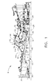
- FIG. 1 Illustrated in FIG. 1 is a gas turbine engine 8 with a high pressure gas generator 10.
- the high pressure gas generator 10 has a high pressure rotor 12 including, in downstream flow relationship, a high pressure compressor 14, a combustor 52, and a high pressure turbine 16.
- the high pressure compressor 14 includes high pressure multiple stage axial compressor stages and a single stage centrifugal compressor 18 as a final compressor stage.
- the rotor 12 is rotatably supported about an engine centerline 28 by a forward bearing 20 in a front frame 22 and a rear bearing 24 disposed downstream of high pressure turbine 16 in a turbine frame 26.
- the exemplary embodiment of the compressor 14 illustrated herein includes a five stage axial compressor 30 followed by the single stage centrifugal compressor 18 having an annular centrifugal compressor impeller 32. Outlet guide vanes 40 are disposed between the five stage axial compressor 30 and the single stage centrifugal compressor 18.
- the compressor 14 includes a forward casing 110 and an aft casing 114.
- the forward casing 110 generally surrounds the axial compressor 30 and the aft casing 114 generally surrounds the centrifugal compressor 18 and supports the diffuser 42 directly downstream of the centrifugal compressor 18.
- the five stage axial compressor 30 includes third and fourth compressor stages 190, 193 of rotatable compressor blades 200 circumferentially surrounded by a blade shroud 69.
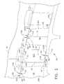
- a circumferential row of non-rotatable stator vanes 204 is disposed axially between the third and fourth compressor stages 190, 193 of the rotatable compressor blades 200. Illustrated in FIGS.
- FIG. 2 and 3 is a compressor blade 200 having a blade airfoil 54 extending radially outwardly from an airfoil base 56 located on the high pressure rotor 12 to a radially outer blade airfoil tip 58 at a free end 87 of the blade airfoil 54 as measured along a span S of the blade airfoil 54.
- the blade airfoil 54 extends downstream from a leading edge LE to a trailing edge TE.
- Each radially outer blade airfoil tip 58 is radially spaced apart and inwardly from and adjacent to a blade rub land 62 of the blade shroud 69 mounted on the compressor forward casing 110.
- An annular rotor airfoil tip clearance 60 is defined between the radially outer blade airfoil tip 58 and the blade rub land 62 on the compressor forward casing 110.
- the stator vanes 204 are cantilevered from and fixed to the forward casing 110 of their radial outward ends 234 and are unsupported at their radial inward ends 236 which are free ends 87.
- a vane airfoil 225 extends radially between the opposite radial outward and inward ends 234, 236. Each vane airfoil 225 extends radially inwardly from a base 228 of the vane airfoil 225 at the outward end 234 of the stator vane 204 to a vane airfoil tip 138 of the vane airfoil 225 at the radial inward end 236 of the stator vane 204.
- the vane airfoil 225 extends downstream from a leading edge LE to a trailing edge TE.
- Each vane airfoil tip 138 is radially spaced apart and outwardly from and adjacent to a rotor seal land 232 on the high pressure rotor 12.
- An annular vane airfoil tip clearance 66 is defined between the vane airfoil tip 138 and the rotor seal land 232 on the high pressure rotor 12.
- compressor discharge pressure (CDP) air 76 is discharged from the impeller 32 of the centrifugal compressor 18 and directly into a diffuser 42 and then through a deswirl cascade 44 into a combustion chamber 45 within the combustor 52.
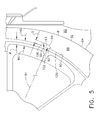
- the impeller 32 includes a plurality of impeller compressor blades 84 including impeller airfoils 88 extending outwardly from impeller airfoil bases 91 on a rotor disc portion 82 to impeller airfoil tips 86 at free ends 87 of the impeller airfoils 88.
- Each of the impeller airfoils 88 extends downstream from a leading edge LE to a trailing edge TE of the impeller airfoil 88.
- An annular centrifugal blade tip shroud 90 surrounds the impeller compressor blades 84 and impeller airfoils 88.
- the centrifugal blade tip shroud 90 is adjacent to the impeller airfoil tips 86 defining an annular impeller airfoil tip clearance 80 therebetween.
- the impeller airfoil tip clearance 80 varies in axial width W in a radial direction R as measured from the engine centerline 28.
- airfoil tip clearances 140 (illustrated herein as the rotor, vane, and impeller airfoil tip clearances 60, 66, 80) between airfoil tips 142 (illustrated herein as the blade, vane, and impeller airfoil tips 58, 138, 86) and annular tip seals 144 (illustrated herein as the blade rub land 62 on the compressor forward casing 110, the rotor seal land 232 on the high pressure rotor 12, and the centrifugal blade tip shroud 90).
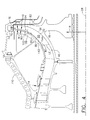
- the rotor and vane airfoil tips 58, 138 and the impeller airfoil tips 86 have recesses 92 located in areas 93 subject to high tip vibratory stress to avoid rubs in the areas 93 of high stress, maintain material properties, and avoid tip cracking.
- the recesses 92 in the airfoil tips and impeller blade tips are located inwardly of the leading and trailing edges LE, TE of the airfoils and are illustrated herein the form of circular scallops 94.
- the airfoil and impeller are solid and the recesses 92 and scallops 94 extend circumferentially completely through the tips.
- the airfoil tips may also have leading and trailing edge corner cuts 96, 98 to further reduce vibratory stress deterioration of the airfoil tips which is particularly useful for thin leading and trailing edges LE, TE.
- the recesses 92 and scallops 94 are formed in or cut into nominal airfoil tip edges 106 of the rotor airfoil tips 58 which is illustrated as a dashed line in FIG. 3 .
- the recesses 92 and scallops 94 are also illustrated as formed from or cut into impeller tip edges 108 of the impeller airfoil tips 86 as illustrated in FIGS. 4 and 5 .
- Nominal airfoil tip and impeller blade tip shapes 100, 102 are illustrated in dashed lines in FIGS. 3 and 5 .
- the nominal shapes are the originally designed tip shapes before the recesses or scallops are formed or cut in the tips.
- the nominal airfoil tip edge 106 are equidistantly spaced apart from the blade rub land 62 and are, thus, conical as illustrated in FIG. 3 or cylindrical.
- the nominal impeller tip edge 108 has an impeller blade tip shape 102 that may be a simple or a compound curve including at least a first sector 120 having a first radius of curvature R1 as illustrated in FIG. 5 .
- the recesses 92 and scallops 94 are very shallow having a maximum depth D of only a few mills such as in a range of about 5-10 mills (.005 - .01 inches) as measured from the nominal airfoil and impeller tip edges 106, 108 respectively for the exemplary engine illustrated herein. Larger engines may have larger recesses or scallops.
- the scallops 94 are circular having a scallop radius SR.
- the scallop radius SR of the scallops 94 in the impeller tip edges 108 of the impeller airfoil tips 86 is smaller than the first radius of curvature R1 of the impeller blade tip shape 102.
- the recesses and scallops can be machined or cut into the airfoil tips adjacent the nicks and scratches.
- the size and depth of the recesses and scallops may be tailored for each individual airfoil and, thus, vary from airfoil to airfoil within a stage or annular row of blades, vanes or impeller blades.
Applications Claiming Priority (1)
| Application Number | Priority Date | Filing Date | Title |
|---|---|---|---|
| US13/253,328 US20130089421A1 (en) | 2011-10-05 | 2011-10-05 | Gas turbine engine airfoil tip recesses |
Publications (1)
| Publication Number | Publication Date |
|---|---|
| EP2578805A1 true EP2578805A1 (en) | 2013-04-10 |
Family
ID=46968073
Family Applications (1)
| Application Number | Title | Priority Date | Filing Date |
|---|---|---|---|
| EP12187063.8A Withdrawn EP2578805A1 (en) | 2011-10-05 | 2012-10-03 | Gas turbine engine airfoil with tip recesses |
Country Status (4)
| Country | Link |
|---|---|
| US (1) | US20130089421A1 (ja) |
| EP (1) | EP2578805A1 (ja) |
| JP (1) | JP2013083251A (ja) |
| CA (1) | CA2791040A1 (ja) |
Cited By (3)
| Publication number | Priority date | Publication date | Assignee | Title |
|---|---|---|---|---|
| EP2963243A1 (de) * | 2014-06-30 | 2016-01-06 | MTU Aero Engines GmbH | Strömungsmaschine mit laufschaufeln mit in richtung der hinterkante abgesenkter schaufelspitze |
| CN108071424A (zh) * | 2016-11-18 | 2018-05-25 | 安萨尔多能源瑞士股份公司 | 燃气涡轮中的叶片与定子隔热罩分界 |
| CN109356884A (zh) * | 2018-12-21 | 2019-02-19 | 大连海事大学 | 一种具有仿生顶室的压气机动叶 |
Families Citing this family (4)
| Publication number | Priority date | Publication date | Assignee | Title |
|---|---|---|---|---|
| GB201508763D0 (en) | 2015-05-22 | 2015-07-01 | Rolls Royce Plc | Rotary blade manufacturing method |
| US10385865B2 (en) * | 2016-03-07 | 2019-08-20 | General Electric Company | Airfoil tip geometry to reduce blade wear in gas turbine engines |
| US10982554B2 (en) * | 2016-10-28 | 2021-04-20 | General Electric Company | Tip shroud for a turbine engine |
| KR102048874B1 (ko) | 2018-04-09 | 2019-11-26 | 두산중공업 주식회사 | 유연성이 향상된 터빈 베인 |
Citations (5)
| Publication number | Priority date | Publication date | Assignee | Title |
|---|---|---|---|---|
| DE3500692A1 (de) * | 1985-01-11 | 1986-07-17 | MTU Motoren- und Turbinen-Union München GmbH, 8000 München | Axial- oder radiallaufschaufelgitter mit einrichtungen zur konstanthaltung des schaufelspitzenspiels |
| EP1101947A2 (en) * | 1999-11-15 | 2001-05-23 | General Electric Company | Rub resistant compressor stage |
| US20030059309A1 (en) * | 2001-09-26 | 2003-03-27 | Szucs Peter Nicholas | Methods and apparatus for improving engine operation |
| JP2004092533A (ja) * | 2002-08-30 | 2004-03-25 | Mitsubishi Heavy Ind Ltd | 回転機械の動翼、回転機械の固定壁、及び、回転翼構造 |
| GB2427901A (en) * | 2005-06-30 | 2007-01-10 | Rolls Royce Plc | Aerofoil blade with a tip having a groove |
Family Cites Families (3)
| Publication number | Priority date | Publication date | Assignee | Title |
|---|---|---|---|---|
| US1317707A (en) * | 1919-10-07 | Inghouse electric | ||
| US4238170A (en) * | 1978-06-26 | 1980-12-09 | United Technologies Corporation | Blade tip seal for an axial flow rotary machine |
| US4349313A (en) * | 1979-12-26 | 1982-09-14 | United Technologies Corporation | Abradable rub strip |
-
2011
- 2011-10-05 US US13/253,328 patent/US20130089421A1/en not_active Abandoned
-
2012
- 2012-09-27 CA CA2791040A patent/CA2791040A1/en not_active Abandoned
- 2012-10-02 JP JP2012219936A patent/JP2013083251A/ja active Pending
- 2012-10-03 EP EP12187063.8A patent/EP2578805A1/en not_active Withdrawn
Patent Citations (5)
| Publication number | Priority date | Publication date | Assignee | Title |
|---|---|---|---|---|
| DE3500692A1 (de) * | 1985-01-11 | 1986-07-17 | MTU Motoren- und Turbinen-Union München GmbH, 8000 München | Axial- oder radiallaufschaufelgitter mit einrichtungen zur konstanthaltung des schaufelspitzenspiels |
| EP1101947A2 (en) * | 1999-11-15 | 2001-05-23 | General Electric Company | Rub resistant compressor stage |
| US20030059309A1 (en) * | 2001-09-26 | 2003-03-27 | Szucs Peter Nicholas | Methods and apparatus for improving engine operation |
| JP2004092533A (ja) * | 2002-08-30 | 2004-03-25 | Mitsubishi Heavy Ind Ltd | 回転機械の動翼、回転機械の固定壁、及び、回転翼構造 |
| GB2427901A (en) * | 2005-06-30 | 2007-01-10 | Rolls Royce Plc | Aerofoil blade with a tip having a groove |
Cited By (5)
| Publication number | Priority date | Publication date | Assignee | Title |
|---|---|---|---|---|
| EP2963243A1 (de) * | 2014-06-30 | 2016-01-06 | MTU Aero Engines GmbH | Strömungsmaschine mit laufschaufeln mit in richtung der hinterkante abgesenkter schaufelspitze |
| US10208616B2 (en) | 2014-06-30 | 2019-02-19 | MTU Aero Engines AG | Turbomachine with blades having blade tips lowering towards the trailing edge |
| CN108071424A (zh) * | 2016-11-18 | 2018-05-25 | 安萨尔多能源瑞士股份公司 | 燃气涡轮中的叶片与定子隔热罩分界 |
| US11255212B2 (en) | 2016-11-18 | 2022-02-22 | Ansaldo Energia Switzerland AG | Blade to stator heat shield interface in a gas turbine |
| CN109356884A (zh) * | 2018-12-21 | 2019-02-19 | 大连海事大学 | 一种具有仿生顶室的压气机动叶 |
Also Published As
| Publication number | Publication date |
|---|---|
| US20130089421A1 (en) | 2013-04-11 |
| CA2791040A1 (en) | 2013-04-05 |
| JP2013083251A (ja) | 2013-05-09 |
Similar Documents
| Publication | Publication Date | Title |
|---|---|---|
| EP2578805A1 (en) | Gas turbine engine airfoil with tip recesses | |
| US10539020B2 (en) | Two spool gas turbine engine with interdigitated turbine section | |
| US10287902B2 (en) | Variable stator vane undercut button | |
| US10544734B2 (en) | Three spool gas turbine engine with interdigitated turbine section | |
| EP2863015A1 (en) | Turbine rotor blade and corresponding manufacturing method | |
| EP2557271B1 (en) | Method of measuring turbine blade tip erosion | |
| CA2547176A1 (en) | Angled blade firtree retaining system | |
| US9869185B2 (en) | Rotating turbine component with preferential hole alignment | |
| US10184345B2 (en) | Cover plate assembly for a gas turbine engine | |
| EP2935837B1 (en) | Segmented seal for a gas turbine engine | |
| US10655481B2 (en) | Cover plate for rotor assembly of a gas turbine engine | |
| EP3048248A1 (en) | Rotor disk boss | |
| US20160319835A1 (en) | A gas turbine engine integrally bladed rotor with asymmetrical trench fillets | |
| RU2594392C2 (ru) | Уплотнительное кольцо для ступени турбины турбомашины летательного аппарата, содержащее запорные выступы с прорезями, ротор ступени турбомашины, турбомашина и способ изготовления уплотнительного кольца | |
| US8925201B2 (en) | Method and apparatus for providing rotor discs | |
| EP3701127B1 (en) | Compressor aerofoil | |
| US20150098802A1 (en) | Shrouded turbine blisk and method of manufacturing same | |
| US8540482B2 (en) | Rotor assembly for gas turbine engine | |
| US9957829B2 (en) | Rotor tip clearance | |
| WO2013181006A1 (en) | Turbine cooling apparatus | |
| RU2638250C2 (ru) | Уплотнение для газотурбинного двигателя | |
| EP3693541B1 (en) | Gas turbine rotor disk having scallop shield feature | |
| US11629722B2 (en) | Impeller shroud frequency tuning rib | |
| GB2543327A (en) | Aerofoil tip profiles | |
| EP3088672A1 (en) | Method for designing a fluid flow engine and fluid flow engine |
Legal Events
| Date | Code | Title | Description |
|---|---|---|---|
| PUAI | Public reference made under article 153(3) epc to a published international application that has entered the european phase |
Free format text: ORIGINAL CODE: 0009012 |
|
| AK | Designated contracting states |
Kind code of ref document: A1 Designated state(s): AL AT BE BG CH CY CZ DE DK EE ES FI FR GB GR HR HU IE IS IT LI LT LU LV MC MK MT NL NO PL PT RO RS SE SI SK SM TR |
|
| AX | Request for extension of the european patent |
Extension state: BA ME |
|
| 17P | Request for examination filed |
Effective date: 20131010 |
|
| RBV | Designated contracting states (corrected) |
Designated state(s): AL AT BE BG CH CY CZ DE DK EE ES FI FR GB GR HR HU IE IS IT LI LT LU LV MC MK MT NL NO PL PT RO RS SE SI SK SM TR |
|
| STAA | Information on the status of an ep patent application or granted ep patent |
Free format text: STATUS: THE APPLICATION IS DEEMED TO BE WITHDRAWN |
|
| 18D | Application deemed to be withdrawn |
Effective date: 20150501 |