EP2578794A1 - Mât de forage et méthode d'érection - Google Patents
Mât de forage et méthode d'érection Download PDFInfo
- Publication number
- EP2578794A1 EP2578794A1 EP12184933.5A EP12184933A EP2578794A1 EP 2578794 A1 EP2578794 A1 EP 2578794A1 EP 12184933 A EP12184933 A EP 12184933A EP 2578794 A1 EP2578794 A1 EP 2578794A1
- Authority
- EP
- European Patent Office
- Prior art keywords
- mast
- base structure
- constrained
- sections
- bar
- Prior art date
- Legal status (The legal status is an assumption and is not a legal conclusion. Google has not performed a legal analysis and makes no representation as to the accuracy of the status listed.)
- Granted
Links
- 238000005553 drilling Methods 0.000 title claims abstract description 36
- 238000000034 method Methods 0.000 title claims description 10
- 230000006835 compression Effects 0.000 claims description 6
- 238000007906 compression Methods 0.000 claims description 6
- 238000009434 installation Methods 0.000 description 2
- 210000001364 upper extremity Anatomy 0.000 description 2
- 238000013475 authorization Methods 0.000 description 1
- 238000010276 construction Methods 0.000 description 1
- 230000001419 dependent effect Effects 0.000 description 1
- 238000000605 extraction Methods 0.000 description 1
- 238000004519 manufacturing process Methods 0.000 description 1
- 239000003129 oil well Substances 0.000 description 1
- 230000000284 resting effect Effects 0.000 description 1
- 238000004804 winding Methods 0.000 description 1
Images


Classifications
-
- E—FIXED CONSTRUCTIONS
- E21—EARTH OR ROCK DRILLING; MINING
- E21B—EARTH OR ROCK DRILLING; OBTAINING OIL, GAS, WATER, SOLUBLE OR MELTABLE MATERIALS OR A SLURRY OF MINERALS FROM WELLS
- E21B15/00—Supports for the drilling machine, e.g. derricks or masts
-
- E—FIXED CONSTRUCTIONS
- E21—EARTH OR ROCK DRILLING; MINING
- E21B—EARTH OR ROCK DRILLING; OBTAINING OIL, GAS, WATER, SOLUBLE OR MELTABLE MATERIALS OR A SLURRY OF MINERALS FROM WELLS
- E21B7/00—Special methods or apparatus for drilling
- E21B7/02—Drilling rigs characterised by means for land transport with their own drive, e.g. skid mounting or wheel mounting
- E21B7/023—Drilling rigs characterised by means for land transport with their own drive, e.g. skid mounting or wheel mounting the mast being foldable or telescopically retractable
Definitions
- the present invention relates to a reclosable mast comprised in a drilling rig for excavating extraction wells, e.g. oil wells.
- Said rig is suitable for use on the ground and can be transported from one location to another by means of trucks and semitrailers.
- Said rig normally comprises a mast, a substructure, a hoist and a structure for supporting the vertical or setback drill pipes.
- Said substructure is made up of base elements resting on the ground, which is levelled and compacted prior to installing the rig; a central structure at the centre of the well, essentially consisting of two strong shoulders; a latticed structure consisting of two side shoulders and a back, with the fourth side left open.
- Said latticed structure comprises beams for supporting the rotary table, and the structure for supporting the vertical or setback drill pipes.
- said latticed structure is hinged to the base elements and can rotate by 90°, e.g. from horizontal to vertical, and vice versa.
- connection elements for lifting means used for erecting the assembled mast, once the assembly is completed e.g. two hydraulic cylinders.
- the structure that supports the vertical drill pipes and the beams that support the rotary table are hinged to the substructure, normally at the front leg of the lattice. Said setback and rotary table beams remain substantially horizontal, and take their final configuration when the mast is in the vertical position.
- the hoist frame is an articulated parallelogram.
- the hoist frame In the final installed position, the hoist frame is secured to the floor where drilling will take place.
- the mast has a three-sided latticed structure, in particular with two side shoulders and a back, the fourth side being open.
- these masts can be divided into a plurality of portions, e.g. four, such as an upper portion, also comprising portions of the hoist, the upper intermediate portion, the lower intermediate portion and the lower portion.
- top drive comprising at least one drill head slideable on guides which are normally installed on the back of the mast lattice.
- a handling system comprising a winding drum, a line, a plurality of pulleys, whereon said line is suitably arranged, and a backup line spooler.
- the mast in the extended configuration has a nominal distance between its shoulders of 9.144 m and a maximum dimension of 9.16 m. These characteristics ensure sufficient room on the drill floor and very good visibility of the top drive.
- the on-site installation of the drilling rig is completed by adding gangways and ladders, a BOP system, and the drill pipe loader.
- the above-mentioned drilling rig is normally used for excavating wells which are relatively not very deep, and which require an average installation time of approximately one month. As a consequence, at regular intervals of about one month it is necessary to disassemble said rig, transport it, and reposition it where a new wellbore is to be drilled.
- the maximum transversal width of the mast is 3.3 m, so that it can be transported with the aid of a technical escort alone including a car and authorized personnel, without requiring the intervention of the highway police.
- Masts are known which can be dismounted and reclosed in order to reduce their dimensions.
- Said masts can be disassembled into a plurality of sections. Said mast is divided into sections prior to transportation, and the lateral dimension of the back thereof is reduced in every single section.
- masts In order to take less room, said masts must be divided into sections before they can be reclosed.
- United States patent US6594960 describes a mast which can be divided into four portions, and which is then reclosed by releasing rear bars forming the back of the mast; the rear bars can be folded through manual means only after the mast has been divided into four portions.
- the rear bars When closing the back of the mast, the rear bars fold up and occupy a portion of the mast structure that, when in use, is occupied by the drilling equipment or top drive. In said mast, the top drive must be removed before one can carry out the mast closing operation.
- United States patent application US2011120043 is also known, which describes a sectionable mast whose sections can be brought into a closed configuration.
- masts In addition to being difficult to assemble/disassemble, these masts are complex to manufacture and excessively costly due to the large number of constraining members. Also, the mast sections are very delicate because, due to their very complex structure, they very often get stuck while switching from the open configuration to the closed configuration, which may result in damage to the components of the mast structure.
- the problem to be solved is, therefore, to articulate the elements of the back of the mast in a manner such that the shoulders can be brought near each other within the specified dimension of 3.3 m, by using a simplified mast structure.
- the present invention aims at overcoming the above-mentioned problems by providing a mast that can be closed to take up less room, and can possibly be divided into a plurality of sections to make transportation easier thanks to the reduced transversal dimension of the mast itself.
- the operations for assembling the mast sections are carried out with the sections closed, i.e. smaller, thereby facilitating the operations for constraining the various parts thereof.
- the mast structure is simplified, thereby facilitating the construction of the mast components and the operations for opening and closing the mast.
- One aspect of the present invention relates to a mast for drilling rigs having the features set out in the appended claim 1.
- a further aspect of the present invention relates to a method of assembling the mast having the features set out in the appended independent claim 11.
- reclosable mast 2 comprised in a drilling rig 1, comprises two opposed latticed structures 22, which are constrained at one end to base structure 10 placed on a drilling site "P" on ground “S” and at the opposite end to each other, thus defining side faces 2b of mast 2.
- said latticed structures 22 are constrained to the external structure of a handling system 12 adapted to actuate the drilling devices or top drive 14, which are adapted to drill a wellbore in drilling site "P". Furthermore, each one of said latticed structures 22 comprises a front leg and a rear leg.
- Said mast 2 comprises a plurality of U-shaped structures, each comprising a rear bar 40, adapted to get compressed when closing mast 2, and two side shoulders 41 parallel to each other and perpendicular to said bar 40, with which they are associated.
- Said U-shaped structures are arranged at preset intervals between the two latticed structures 22, so that said rear bars define a rear face or back 2a of mast 2.
- Said mast 2 further comprises a plurality of diagonal members 3, located on rear face 2a of the mast and constrained, when in use, between two superimposed U-shaped structures.
- each one of said diagonal members 3 is removably constrained between two consecutive superimposed U-shaped structures.
- said diagonal members 3 are adapted to split into at least two portions to reduce their longitudinal extension.
- Said diagonal members 3, which are adapted to reduce their longitudinal extension, are telescopic.
- diagonal members 2 of this type are arranged between U-shaped structures located at the upper end of the mast.
- Said rear bar 40 comprised in each U-shaped structure of said upper portion of mast 2 is telescopic and is adapted to get compressed as mast 2 is being closed.
- said splittable diagonal members 3 comprise at least one constraining member 32, which is adapted to, when in use, removably fix the portions of diagonal member 3 itself.
- diagonal members 3 of this type are placed between U-shaped structures located at the lower end of mast 2. When said diagonal members 3 are disconnected at the centre, the two portions 3a and 3b are brought into the transportation position, parallel to the rear legs of latticed structure 22.
- said at least one constraining member 32 is of the double-hinge type and is located at the centre of diagonal member 3 itself.
- said rear bar 40 comprised in the U-shape structures is articulated and comprises at least three hinge points 401 adapted to allow for accordion-type compression of bar 40 when closing mast 2. When it is compressed, said bar 40 arranges itself on the surface defined by rear face 2a of mast 2.
- said hinge points are double hinges; furthermore, as shown in the drawings, said hinge points 401 are six and are adapted to connect five elements to each other and to the structure of mast 2. Said five elements, thanks to said hinge points 401, arrange themselves in an accordion-like fashion when said mast 2 is closed.
- the central element of rear bar 40 is constrained to a vertical beam 16 adapted to guide the movement of the drilling devices or top drive 14; instead, the elements adjacent to the central element of rear bar 40 articulate themselves, thanks to hinge points 401, into an accordion-like shape.
- At least one actuator 43 is associated with each U-shaped structure, which actuator is adapted to contribute to the extension/compression of rear bar 40 for opening/closing mast 2.
- said at least one actuator 43 is constrained at one end to said U-shaped structure, and at the opposite end to a latticed structure 22.
- two actuators 43 arranged at the ends of bar 40 contribute to the compression of bar 40.
- said actuator 43 is a hydraulic or pneumatic cylinder, as shown in Fig. 8B .
- said at least one actuator is constrained to the telescopic elements of bar 40 itself, so as to allow for mutual telescopic sliding of the elements of bar 40.
- there are two actuators 43 e.g. two hydraulic or pneumatic cylinders, each connected at one end to the fixed portion of the telescopic element of bar 40 and at the opposite end to the respective ends of bar 40 itself, as shown in Fig. 8A .
- the last U-shaped structure in the lowest potion of mast 2 comprises diagonal bars 31, which are connected to base structure 10 when mast 2 is assembled to drilling rig 1.
- diagonal bars 31 When said diagonal bars 31 are released, they are arranged parallel to at least one leg of latticed structure 22 to which they are constrained.
- mast 2 can essentially take two distinct operating configurations, in particular:
- Mast 2 in the open configuration has rear bars 40 extended and constrained, and diagonal members 3 suitably constrained as well, so as to obtain the maximum transversal dimension of the rear face or back 2a.
- This operating configuration is the one normally used during the drilling operations.
- Mast 2 in the closed configuration has rear bars 40 compressed and diagonal members 3 split and reduced in size, so as to reduce the transversal dimension of the rear face or back 2a of mast 2.
- This operating configuration is the one normally employed when transporting the mast to a new drilling site.
- the maximum transversal dimension of back 2a is approximately 3.3 m, as required for transportation on two-way two-lane roads.
- splittable diagonal members 3 are divided into sections, whereas the telescopic diagonal members are contracted.
- constraining member 32 is released on splittable diagonal members 3, e.g. by extracting the pins of a double hinge.
- bars 40 in the upper portion of mast 2 are contracted telescopically, whereas bars 40 in the lower portion of mast 2 are compressed in an accordion-like fashion.
- hinge points 401 are suitably released.
- actuators 43 contribute to the compression of rear bars 40, thus preventing said bar 40 from getting stuck as it is being compressed, which might cause damage to whole mast 2.
- the splitting, reduction and compression steps are carried out at the same time.
- bars 40 in the upper portion of mast 2 are extended telescopically, e.g. by means of actuator 43; bars 40 in the lower portion of mast 2 are extended to assume a substantially straight shape, and hinge points 401 are suitably constrained, thereby preventing rear bar 40 from being unintentionally compressed.
- said mast 2 can be divided into a plurality of sections which, when in use, are removably constrained to each other.
- said mast 2 can be divided into four sections, in particular: an upper section 20a; an upper intermediate section 20b, a lower intermediate section 20c, a lower section 20d.
- Latticed structures 22 are hinged at one end to the structure of at least one crown block comprised in handling system 12, while at the opposite end they comprise connectors 221, preferably of the double-hinge type, which are adapted to connect said section 20a to the upper intermediate section 20b.
- Diagonal members 3 and rear bars 40 comprised in back 2a are telescopic and have two fastening positions for the connection to latticed structures 22.
- said handling system comprises: at least one drawworks, at least one crown block, at least one travelling block, at least one drilling line, at least one dead line anchor, and at least one backup spooler.
- Upper intermediate section 20b comprises, at each end of latticed structures 22, connectors 221, e.g. of the double-hinge type, for the connection to the rear section 2a and to the upper intermediate section 2b.
- rear bars 40 comprise five elements interconnected through said hinge points 401, which, when loosened up, take an accordion-like shape in the closed operating configuration of the mast.
- Diagonal members 3 are constrained at their ends, e.g. to the U-shaped structures, by means of a hinge, whereas at the centre the two sections are connected through at least one constraining member 32.
- said constraining members 32 are disconnected, thereby releasing the two portions 3a and 3b.
- Said released portions 3a and 3b are preferably arranged, in the closed operating configuration, parallel to latticed structure 22 to which the single portion is constrained, e.g. a leg.
- the principle of operation of the lower intermediate section 20c is substantially similar to the above-mentioned upper intermediate section 2b.
- the statement that the principle of operation is substantially similar means that the U-shaped structures and diagonal members 3 comprised in different sections of mast 2 have the same principle of operation, even though their structural dimensions are different.
- Lower section 20d whose principle of operation is substantially similar to that of the preceding intermediate sections (20b, 20c), additionally comprises two diagonal bars 31, each secured at one end to at least one latticed structure 22, e.g. a leg, and at the opposite end to base structure 10, thus assuming as a whole a "V" shape.
- the steps for switching mast 2 from the open configuration to the closed configuration may comprise one or more sectioning steps, which can be carried out either before the division and reduction step or after the step of bringing latticed structures 22 near each other.
- the steps for switching mast 2 from the closed configuration to the open configuration may comprise one or more steps of connecting together two or more sections; said steps can be carried out either before the step of moving latticed structures 22 mutually away from each other or after the step of reconnecting and increasing the longitudinal dimension of diagonal members 3.
- the method of assembling mast 2 according to the present invention to a drilling rig 1 comprises the following steps:
- Said mast 1 is formed by two side faces 2b and one rear face 2a, which can be closed. Said mast 2 is constrained, when in use, to a base structure 10.
- Said base structure 10 comprises a plurality of support members or sub-base 102, a plurality of connection crosspieces, a central structure, a three-sided latticed structure 103, and at least one lifting means 101 for lifting mast 2 from a position substantially parallel to ground "S" to a position substantially vertical over base structure 10.
- the expression “substantially horizontal” means that the longitudinal axis of mast 2 has an angle of inclination relative to ground “S” of less than 6°, whereas the expression “substantially vertical” means that the longitudinal axis of mast 2 has an angle of inclination relative to the normal to the surface of ground “S” within +6°.
- the plurality of elements comprised in base structure 10 are mounted by using cranes in accordance with traditional methods.
- the support members or sub-base 102 and the connection crosspieces are first positioned, and then the central structure and the three-sided latticed structure 103 are installed, the latter being arranged in a horizontal position, parallel to ground "S", at a predetermined height "Z2" from the ground, to which mast 2 will be secured.
- Said three-sided latticed structure 103 is preferably hinged at one end, and is supported by said at least one lifting means 101, e.g. a plurality of hydraulic pistons.
- the support members or sub-base 102 are mounted in such a way as to reach lifting means 101.
- the greater extension of the support members or sub-base 101 will ensure better stability of base structure 10 and of mast 2 during the next step of erecting mast 2.
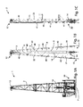
- At least two trestles 18 are also positioned, preferably a first trestle 18', placed proximal to base structure 10, e.g. near the end of the extension of sub-base 102, and a second trestle 18", placed at a distance from said first trestle 18', which is shorter than the maximum extension of mast 2, preferably substantially matching the longitudinal extension of mast 2 from the centre of lower section 20d to the centre of upper section 20a.
- the positioning step is followed by the step of connecting the plurality of sections (20a, 20b, 20c, 20d).
- said sections (20a, 20b, 20c, 20d) are initially positioned and fastened by positioning the lower section 20d on said first trestle 18', and then positioning the lower intermediate section 20c near lower section 20d and connecting it to the same lower section 20d through the above-mentioned connectors 221.
- Said sections (20a, 20b, 20c, 20d) are at least partly supported by at least one carriage 17 adapted to support sections (20a, 20b, 20c, 20d) while assembling the mast 2.
- lower section 20d is placed on first trestle 18' in a manner such that lowest U-shaped structure, comprised in same lower section 20d, is in the proximity of said trestle 18'.
- the term "lowest U-shaped structure” refers to that U-shaped structure, comprised in mast 2, which is closest, when in use, to the base structure 10.
- upper U-shaped structure comprised in upper section 20a is placed on second trestle 18".
- upper U-shaped structure refers to that U-shaped structure, comprised in mast 2, which is closest, when in use, to handling system 12.
- connection of the plurality of sections (20a, 20b, 20c, 20d) occurs at a first height "Z1" from the surface of ground “S", lower than the above-mentioned height "Z2", so that mast 2 is assembled horizontally, i.e. parallel to ground "S".
- mast 2 is assembled horizontally means that mast 2, by means of said support trestles 18, is assembled parallel to ground “S” where said drilling rig 1 is being assembled.
- mast 2 is placed at a first height "Z1" from ground “S" which is equal to, for example, approximately 1.5 m, as shown in Fig. 9E .
- mast 2 has been assembled by connecting together the various mast sections (20a, 20b, 20c, 20d), the next step of extending rear face 2a of mast 2 is carried out.
- mast 2 switches from the closed operating configuration to the open operating configuration.
- the above-mentioned steps for opening mast 2 are carried out.
- the step of extending rear face 2a of mast 2 is followed by the step of lifting mast 2 to the height "Z2" from ground “S".
- mast 2 which is kept parallel to ground “S”
- said height "Z2" is where the three-sided latticed structure 103 is located.
- said height "Z2" is approximately 4 m above ground "S”.
- the lifting step is followed by the step of bringing mast 2 near base structure 10; in fact, in order to further facilitate the assembly of mast 2, the first trestle 18' is arranged in a manner such that connectors 221 comprised in lower section 20d of mast 2 are at a predetermined distance "X1" from matching connectors 221 of base structure 10, as shown in Figs. 9B ⁇ 9E.
- Said predetermined distance "X1”, e.g. approximately 0.5 m, prevents mast 2 from abutting against base structure 10 during the step of lifting mast 2 from height "Z1" to height "Z2". Moreover, setting mast 2 at the predetermined distance "X1" from base structure 10 facilitates the assembly operations carried out by the personnel in charge. By setting back mast 2 by distance "X1" it is possible to perfectly match connectors 221 of base structure 10 with the connectors 221 of lower section 20d of mast 2.
- the above-mentioned steps of extending, lifting and bringing near are carried out by means of said at least two support trestles 18; in fact, said trestles 18 are adapted to extend, lift and bring mast 2 near base structure 10.
- Said trestles 18 comprise a plurality of actuators adapted to handle the mast, in a predetermined manner, in the orthogonal space defined by axes "X", "Y” and “Z" orthogonal to each other.
- Said trestles 19 comprise a plurality of brackets (not shown) for constraining the latticed structures 22 of the mast, in order to allow mast 2 to be switched from the closed operating configuration to the open operating configuration.
- Said actuators comprised in each trestle 18, are preferably hydraulic pistons, preferably arranged in a manner such that at least one acts along axis "X", at least one acts along axis "Y”, and at least one acts along axis "Z".
- the step of bringing near is followed by the step of fixing mast 2 to base structure 10 through connectors 221.
- mast 2 facilitates and reduces the operations necessary for assembling/disassembling the mast itself, while reducing transportation costs because the overall dimension does not exceed the prescribed limit for exceptional transportations on two-way roads requiring an escort from the road authorities, e.g. the highway police.
- mast 2 according to the present invention can be transported as a whole in the vertical position by using special transportation structures.
- the distances that can be covered are in such a case of the order of a few miles only.
- the width dimension can be reduced by articulating rear face or back 2a of mast 2. Entire mast 2 can thus be transported with a reduced transversal dimension of back 2a.
- said mast can be divided into sections.
- the elements that constitute the mast according to the present invention allow to quickly switch between the two above-mentioned operating configurations, thereby reducing the time necessary for assembling the whole drilling rig and requiring a reduced manual contribution for such operations compared to prior-art masts.
- trestles 18 allows to speed up the operations for assembling the mast to drilling rig 1.
- the use of trestles 18 in combination with mast 2 according to the present invention significantly speeds up the assembly of the drilling rig, in that many assembling steps are simplified and automated.
Landscapes
- Engineering & Computer Science (AREA)
- Geology (AREA)
- Life Sciences & Earth Sciences (AREA)
- Mining & Mineral Resources (AREA)
- Environmental & Geological Engineering (AREA)
- Fluid Mechanics (AREA)
- Physics & Mathematics (AREA)
- General Life Sciences & Earth Sciences (AREA)
- Geochemistry & Mineralogy (AREA)
- Mechanical Engineering (AREA)
- Earth Drilling (AREA)
- Pressure Welding/Diffusion-Bonding (AREA)
- Shafts, Cranks, Connecting Bars, And Related Bearings (AREA)
Applications Claiming Priority (1)
| Application Number | Priority Date | Filing Date | Title |
|---|---|---|---|
| IT000883A ITTO20110883A1 (it) | 2011-10-04 | 2011-10-04 | Albero per impianti di perforazione e relativo metodo di assemblaggio. |
Publications (2)
| Publication Number | Publication Date |
|---|---|
| EP2578794A1 true EP2578794A1 (fr) | 2013-04-10 |
| EP2578794B1 EP2578794B1 (fr) | 2015-01-21 |
Family
ID=44993787
Family Applications (1)
| Application Number | Title | Priority Date | Filing Date |
|---|---|---|---|
| EP12184933.5A Active EP2578794B1 (fr) | 2011-10-04 | 2012-09-19 | Mât de forage et méthode d'érection |
Country Status (3)
| Country | Link |
|---|---|
| US (1) | US8991107B2 (fr) |
| EP (1) | EP2578794B1 (fr) |
| IT (1) | ITTO20110883A1 (fr) |
Families Citing this family (9)
| Publication number | Priority date | Publication date | Assignee | Title |
|---|---|---|---|---|
| US9574402B2 (en) * | 2013-02-12 | 2017-02-21 | Nabors Drilling USA | Box frame spreader beam |
| US9764932B2 (en) * | 2013-05-10 | 2017-09-19 | Paceco Corp. | Jacking tower installation system |
| WO2017214148A1 (fr) | 2016-06-07 | 2017-12-14 | Nabors Drilling Technologies Usa, Inc. | Appareil de forage à catapulte à selle latérale |
| WO2018085850A1 (fr) * | 2016-11-07 | 2018-05-11 | Nabors Drilling Technologies Usa, Inc. | Mât en porte-à-faux du type latéral |
| US10837238B2 (en) | 2018-07-19 | 2020-11-17 | Nabors Drilling Technologies Usa, Inc. | Side saddle slingshot continuous motion rig |
| USD1017832S1 (en) * | 2020-07-17 | 2024-03-12 | Global Engineers Investment Singapore Pte. Ltd. | Tower |
| US11873685B2 (en) | 2020-09-01 | 2024-01-16 | Nabors Drilling Technologies Usa, Inc. | Side saddle traversable drilling rig |
| CN115370218B (zh) * | 2022-09-02 | 2023-08-25 | 浙江八方电信有限公司 | 带有避雷针架升降机构的通讯塔 |
| CN115354901B (zh) * | 2022-09-02 | 2023-08-25 | 浙江八方电信有限公司 | 天支升降式的通讯塔 |
Citations (4)
| Publication number | Priority date | Publication date | Assignee | Title |
|---|---|---|---|---|
| US2176965A (en) * | 1938-02-17 | 1939-10-24 | Haynes Albert | Collapsible derrick |
| US4604844A (en) * | 1985-07-30 | 1986-08-12 | The United States Of America As Represented By The Administrator Of The National Aeronautics And Space Administration | Deployable M-braced truss structure |
| US6594960B2 (en) | 2001-09-18 | 2003-07-22 | Woolslayer Companies, Inc. | Method of folding an articulating mast |
| US20110120043A1 (en) | 2009-11-23 | 2011-05-26 | Woolslayer Companies, Inc. | Articulating Mast |
Family Cites Families (21)
| Publication number | Priority date | Publication date | Assignee | Title |
|---|---|---|---|---|
| USRE25010E (en) * | 1961-07-18 | poetker | ||
| US848304A (en) * | 1906-12-03 | 1907-03-26 | John S Hines | Sectional derrick. |
| US2225561A (en) * | 1938-07-11 | 1940-12-17 | Lee C Moore & Company Inc | Derrick |
| US2413149A (en) * | 1944-06-28 | 1946-12-24 | Robert E Mccarthy | Portable derrick |
| US2835358A (en) * | 1952-08-28 | 1958-05-20 | Hubert J Lusum | Form carrier and form skeleton constructed therewith |
| US2847097A (en) * | 1953-05-21 | 1958-08-12 | United States Steel Corp | Portable mast |
| US2982379A (en) * | 1958-06-23 | 1961-05-02 | Up Right Inc | Folding tower |
| US3011586A (en) * | 1958-10-07 | 1961-12-05 | Jr John E Harvey | Fold-up tower section |
| US3802137A (en) * | 1972-04-03 | 1974-04-09 | Gulf Offshore Co | Offshore well rig |
| US4393630A (en) * | 1981-03-12 | 1983-07-19 | Crane Carrier Corporation | Actuation means for the racking platform of a mast |
| US4725179A (en) * | 1986-11-03 | 1988-02-16 | Lee C. Moore Corporation | Automated pipe racking apparatus |
| US4958474A (en) * | 1987-05-18 | 1990-09-25 | Astro Aerospace Corporation | Truss structure |
| JPH0794236B2 (ja) * | 1989-03-31 | 1995-10-11 | 富士重工業株式会社 | 展開構造物 |
| CA2157340C (fr) * | 1994-09-27 | 1998-06-09 | Donald C. Hade, Jr. | Voie porteuse pour le fonctionnement independant et/ou synchronise des sections d'une fleche telescopique en plusieurs sections |
| US5845451A (en) * | 1996-01-31 | 1998-12-08 | Tolentino; Edgar Williams | Telescoping polygonal figure |
| US7716897B2 (en) * | 2001-07-03 | 2010-05-18 | Merrifield Donald V | Deployable rectangular truss beam with orthogonally-hinged folding diagonals |
| US7780121B2 (en) * | 2005-05-06 | 2010-08-24 | General Electric Company | Wayside signal apparatus with adjustable signal position |
| US20060278394A1 (en) * | 2005-06-09 | 2006-12-14 | Ronnie Stover | System and method for perforating and fracturing in a well |
| ITTO20070257A1 (it) * | 2007-04-13 | 2008-10-14 | Drillmec Spa | Impianto di perforazione o manutenzione per pozzi petroliferi. |
| US8813436B2 (en) * | 2008-02-29 | 2014-08-26 | National Oilwell Varco, L.P. | Pinned structural connection using a pin and plug arrangement |
| DE202008009284U1 (de) * | 2008-07-10 | 2009-11-12 | Daas, Kamal | Tragwerksystem |
-
2011
- 2011-10-04 IT IT000883A patent/ITTO20110883A1/it unknown
-
2012
- 2012-09-19 EP EP12184933.5A patent/EP2578794B1/fr active Active
- 2012-10-04 US US13/645,203 patent/US8991107B2/en active Active
Patent Citations (4)
| Publication number | Priority date | Publication date | Assignee | Title |
|---|---|---|---|---|
| US2176965A (en) * | 1938-02-17 | 1939-10-24 | Haynes Albert | Collapsible derrick |
| US4604844A (en) * | 1985-07-30 | 1986-08-12 | The United States Of America As Represented By The Administrator Of The National Aeronautics And Space Administration | Deployable M-braced truss structure |
| US6594960B2 (en) | 2001-09-18 | 2003-07-22 | Woolslayer Companies, Inc. | Method of folding an articulating mast |
| US20110120043A1 (en) | 2009-11-23 | 2011-05-26 | Woolslayer Companies, Inc. | Articulating Mast |
Also Published As
| Publication number | Publication date |
|---|---|
| US20130180185A1 (en) | 2013-07-18 |
| EP2578794B1 (fr) | 2015-01-21 |
| US8991107B2 (en) | 2015-03-31 |
| ITTO20110883A1 (it) | 2013-04-05 |
Similar Documents
| Publication | Publication Date | Title |
|---|---|---|
| EP2578794B1 (fr) | Mât de forage et méthode d'érection | |
| AU2013228093B2 (en) | Modular drilling rig system | |
| RU2564297C2 (ru) | Быстро транспортируемая буровая установка | |
| CA2781076C (fr) | Procede et systeme pour faciliter l'assemblage d'une installation de fo age | |
| CA2731107C (fr) | Plate-forme de forage a multiples trous, multiples fonctions | |
| EP2805005B1 (fr) | Substructure repliable pour une installation de forage mobile | |
| US9163462B2 (en) | Bi-directionally raisable drilling rig mast | |
| CA2783675C (fr) | Appareil de forage multifonctionnel de trous multiples | |
| US8863449B2 (en) | Substructure of a mobile drilling rig with a movable center floor section | |
| US20090000218A1 (en) | Land rig | |
| WO2009106860A2 (fr) | Procédé et appareil pour faciliter l’assemblage et l’élévation d’une installation de forage | |
| ITTO20120414A1 (it) | Apparato di trivellazione e metodo di assemblaggio e disassemblaggio. | |
| NL2015504B1 (en) | Modular drilling rig system. |
Legal Events
| Date | Code | Title | Description |
|---|---|---|---|
| PUAI | Public reference made under article 153(3) epc to a published international application that has entered the european phase |
Free format text: ORIGINAL CODE: 0009012 |
|
| AK | Designated contracting states |
Kind code of ref document: A1 Designated state(s): AL AT BE BG CH CY CZ DE DK EE ES FI FR GB GR HR HU IE IS IT LI LT LU LV MC MK MT NL NO PL PT RO RS SE SI SK SM TR |
|
| AX | Request for extension of the european patent |
Extension state: BA ME |
|
| 17P | Request for examination filed |
Effective date: 20131002 |
|
| RBV | Designated contracting states (corrected) |
Designated state(s): AL AT BE BG CH CY CZ DE DK EE ES FI FR GB GR HR HU IE IS IT LI LT LU LV MC MK MT NL NO PL PT RO RS SE SI SK SM TR |
|
| GRAP | Despatch of communication of intention to grant a patent |
Free format text: ORIGINAL CODE: EPIDOSNIGR1 |
|
| INTG | Intention to grant announced |
Effective date: 20140804 |
|
| RIN1 | Information on inventor provided before grant (corrected) |
Inventor name: FERRARI, STEFANO |
|
| GRAS | Grant fee paid |
Free format text: ORIGINAL CODE: EPIDOSNIGR3 |
|
| GRAA | (expected) grant |
Free format text: ORIGINAL CODE: 0009210 |
|
| AK | Designated contracting states |
Kind code of ref document: B1 Designated state(s): AL AT BE BG CH CY CZ DE DK EE ES FI FR GB GR HR HU IE IS IT LI LT LU LV MC MK MT NL NO PL PT RO RS SE SI SK SM TR |
|
| REG | Reference to a national code |
Ref country code: GB Ref legal event code: FG4D |
|
| REG | Reference to a national code |
Ref country code: CH Ref legal event code: EP |
|
| REG | Reference to a national code |
Ref country code: IE Ref legal event code: FG4D |
|
| REG | Reference to a national code |
Ref country code: DE Ref legal event code: R096 Ref document number: 602012005018 Country of ref document: DE Effective date: 20150305 |
|
| REG | Reference to a national code |
Ref country code: AT Ref legal event code: REF Ref document number: 709292 Country of ref document: AT Kind code of ref document: T Effective date: 20150315 |
|
| REG | Reference to a national code |
Ref country code: AT Ref legal event code: MK05 Ref document number: 709292 Country of ref document: AT Kind code of ref document: T Effective date: 20150121 |
|
| REG | Reference to a national code |
Ref country code: LT Ref legal event code: MG4D |
|
| REG | Reference to a national code |
Ref country code: NO Ref legal event code: T2 Effective date: 20150121 |
|
| PG25 | Lapsed in a contracting state [announced via postgrant information from national office to epo] |
Ref country code: LT Free format text: LAPSE BECAUSE OF FAILURE TO SUBMIT A TRANSLATION OF THE DESCRIPTION OR TO PAY THE FEE WITHIN THE PRESCRIBED TIME-LIMIT Effective date: 20150121 Ref country code: SE Free format text: LAPSE BECAUSE OF FAILURE TO SUBMIT A TRANSLATION OF THE DESCRIPTION OR TO PAY THE FEE WITHIN THE PRESCRIBED TIME-LIMIT Effective date: 20150121 Ref country code: ES Free format text: LAPSE BECAUSE OF FAILURE TO SUBMIT A TRANSLATION OF THE DESCRIPTION OR TO PAY THE FEE WITHIN THE PRESCRIBED TIME-LIMIT Effective date: 20150121 Ref country code: FI Free format text: LAPSE BECAUSE OF FAILURE TO SUBMIT A TRANSLATION OF THE DESCRIPTION OR TO PAY THE FEE WITHIN THE PRESCRIBED TIME-LIMIT Effective date: 20150121 Ref country code: HR Free format text: LAPSE BECAUSE OF FAILURE TO SUBMIT A TRANSLATION OF THE DESCRIPTION OR TO PAY THE FEE WITHIN THE PRESCRIBED TIME-LIMIT Effective date: 20150121 Ref country code: BG Free format text: LAPSE BECAUSE OF FAILURE TO SUBMIT A TRANSLATION OF THE DESCRIPTION OR TO PAY THE FEE WITHIN THE PRESCRIBED TIME-LIMIT Effective date: 20150421 |
|
| PG25 | Lapsed in a contracting state [announced via postgrant information from national office to epo] |
Ref country code: AT Free format text: LAPSE BECAUSE OF FAILURE TO SUBMIT A TRANSLATION OF THE DESCRIPTION OR TO PAY THE FEE WITHIN THE PRESCRIBED TIME-LIMIT Effective date: 20150121 Ref country code: LV Free format text: LAPSE BECAUSE OF FAILURE TO SUBMIT A TRANSLATION OF THE DESCRIPTION OR TO PAY THE FEE WITHIN THE PRESCRIBED TIME-LIMIT Effective date: 20150121 Ref country code: RS Free format text: LAPSE BECAUSE OF FAILURE TO SUBMIT A TRANSLATION OF THE DESCRIPTION OR TO PAY THE FEE WITHIN THE PRESCRIBED TIME-LIMIT Effective date: 20150121 Ref country code: PL Free format text: LAPSE BECAUSE OF FAILURE TO SUBMIT A TRANSLATION OF THE DESCRIPTION OR TO PAY THE FEE WITHIN THE PRESCRIBED TIME-LIMIT Effective date: 20150121 Ref country code: IS Free format text: LAPSE BECAUSE OF FAILURE TO SUBMIT A TRANSLATION OF THE DESCRIPTION OR TO PAY THE FEE WITHIN THE PRESCRIBED TIME-LIMIT Effective date: 20150521 |
|
| REG | Reference to a national code |
Ref country code: DE Ref legal event code: R097 Ref document number: 602012005018 Country of ref document: DE |
|
| PG25 | Lapsed in a contracting state [announced via postgrant information from national office to epo] |
Ref country code: DK Free format text: LAPSE BECAUSE OF FAILURE TO SUBMIT A TRANSLATION OF THE DESCRIPTION OR TO PAY THE FEE WITHIN THE PRESCRIBED TIME-LIMIT Effective date: 20150121 Ref country code: EE Free format text: LAPSE BECAUSE OF FAILURE TO SUBMIT A TRANSLATION OF THE DESCRIPTION OR TO PAY THE FEE WITHIN THE PRESCRIBED TIME-LIMIT Effective date: 20150121 Ref country code: RO Free format text: LAPSE BECAUSE OF FAILURE TO SUBMIT A TRANSLATION OF THE DESCRIPTION OR TO PAY THE FEE WITHIN THE PRESCRIBED TIME-LIMIT Effective date: 20150121 Ref country code: SK Free format text: LAPSE BECAUSE OF FAILURE TO SUBMIT A TRANSLATION OF THE DESCRIPTION OR TO PAY THE FEE WITHIN THE PRESCRIBED TIME-LIMIT Effective date: 20150121 Ref country code: CZ Free format text: LAPSE BECAUSE OF FAILURE TO SUBMIT A TRANSLATION OF THE DESCRIPTION OR TO PAY THE FEE WITHIN THE PRESCRIBED TIME-LIMIT Effective date: 20150121 |
|
| PLBE | No opposition filed within time limit |
Free format text: ORIGINAL CODE: 0009261 |
|
| STAA | Information on the status of an ep patent application or granted ep patent |
Free format text: STATUS: NO OPPOSITION FILED WITHIN TIME LIMIT |
|
| 26N | No opposition filed |
Effective date: 20151022 |
|
| PG25 | Lapsed in a contracting state [announced via postgrant information from national office to epo] |
Ref country code: IT Free format text: LAPSE BECAUSE OF FAILURE TO SUBMIT A TRANSLATION OF THE DESCRIPTION OR TO PAY THE FEE WITHIN THE PRESCRIBED TIME-LIMIT Effective date: 20150121 |
|
| PG25 | Lapsed in a contracting state [announced via postgrant information from national office to epo] |
Ref country code: SI Free format text: LAPSE BECAUSE OF FAILURE TO SUBMIT A TRANSLATION OF THE DESCRIPTION OR TO PAY THE FEE WITHIN THE PRESCRIBED TIME-LIMIT Effective date: 20150121 |
|
| PG25 | Lapsed in a contracting state [announced via postgrant information from national office to epo] |
Ref country code: LU Free format text: LAPSE BECAUSE OF FAILURE TO SUBMIT A TRANSLATION OF THE DESCRIPTION OR TO PAY THE FEE WITHIN THE PRESCRIBED TIME-LIMIT Effective date: 20150919 Ref country code: MC Free format text: LAPSE BECAUSE OF FAILURE TO SUBMIT A TRANSLATION OF THE DESCRIPTION OR TO PAY THE FEE WITHIN THE PRESCRIBED TIME-LIMIT Effective date: 20150121 |
|
| REG | Reference to a national code |
Ref country code: CH Ref legal event code: PL |
|
| PG25 | Lapsed in a contracting state [announced via postgrant information from national office to epo] |
Ref country code: BE Free format text: LAPSE BECAUSE OF FAILURE TO SUBMIT A TRANSLATION OF THE DESCRIPTION OR TO PAY THE FEE WITHIN THE PRESCRIBED TIME-LIMIT Effective date: 20150121 |
|
| REG | Reference to a national code |
Ref country code: IE Ref legal event code: MM4A |
|
| PG25 | Lapsed in a contracting state [announced via postgrant information from national office to epo] |
Ref country code: CH Free format text: LAPSE BECAUSE OF NON-PAYMENT OF DUE FEES Effective date: 20150930 Ref country code: IE Free format text: LAPSE BECAUSE OF NON-PAYMENT OF DUE FEES Effective date: 20150919 Ref country code: LI Free format text: LAPSE BECAUSE OF NON-PAYMENT OF DUE FEES Effective date: 20150930 |
|
| REG | Reference to a national code |
Ref country code: FR Ref legal event code: PLFP Year of fee payment: 5 |
|
| PGFP | Annual fee paid to national office [announced via postgrant information from national office to epo] |
Ref country code: GB Payment date: 20160914 Year of fee payment: 5 |
|
| PGFP | Annual fee paid to national office [announced via postgrant information from national office to epo] |
Ref country code: FR Payment date: 20160816 Year of fee payment: 5 |
|
| PG25 | Lapsed in a contracting state [announced via postgrant information from national office to epo] |
Ref country code: MT Free format text: LAPSE BECAUSE OF FAILURE TO SUBMIT A TRANSLATION OF THE DESCRIPTION OR TO PAY THE FEE WITHIN THE PRESCRIBED TIME-LIMIT Effective date: 20150121 |
|
| PG25 | Lapsed in a contracting state [announced via postgrant information from national office to epo] |
Ref country code: HU Free format text: LAPSE BECAUSE OF FAILURE TO SUBMIT A TRANSLATION OF THE DESCRIPTION OR TO PAY THE FEE WITHIN THE PRESCRIBED TIME-LIMIT; INVALID AB INITIO Effective date: 20120919 Ref country code: SM Free format text: LAPSE BECAUSE OF FAILURE TO SUBMIT A TRANSLATION OF THE DESCRIPTION OR TO PAY THE FEE WITHIN THE PRESCRIBED TIME-LIMIT Effective date: 20150121 |
|
| PG25 | Lapsed in a contracting state [announced via postgrant information from national office to epo] |
Ref country code: CY Free format text: LAPSE BECAUSE OF FAILURE TO SUBMIT A TRANSLATION OF THE DESCRIPTION OR TO PAY THE FEE WITHIN THE PRESCRIBED TIME-LIMIT Effective date: 20150121 Ref country code: GR Free format text: LAPSE BECAUSE OF FAILURE TO SUBMIT A TRANSLATION OF THE DESCRIPTION OR TO PAY THE FEE WITHIN THE PRESCRIBED TIME-LIMIT Effective date: 20150121 |
|
| PG25 | Lapsed in a contracting state [announced via postgrant information from national office to epo] |
Ref country code: TR Free format text: LAPSE BECAUSE OF FAILURE TO SUBMIT A TRANSLATION OF THE DESCRIPTION OR TO PAY THE FEE WITHIN THE PRESCRIBED TIME-LIMIT Effective date: 20150121 |
|
| GBPC | Gb: european patent ceased through non-payment of renewal fee |
Effective date: 20170919 |
|
| PG25 | Lapsed in a contracting state [announced via postgrant information from national office to epo] |
Ref country code: PT Free format text: LAPSE BECAUSE OF FAILURE TO SUBMIT A TRANSLATION OF THE DESCRIPTION OR TO PAY THE FEE WITHIN THE PRESCRIBED TIME-LIMIT Effective date: 20150121 Ref country code: MK Free format text: LAPSE BECAUSE OF FAILURE TO SUBMIT A TRANSLATION OF THE DESCRIPTION OR TO PAY THE FEE WITHIN THE PRESCRIBED TIME-LIMIT Effective date: 20150121 |
|
| REG | Reference to a national code |
Ref country code: FR Ref legal event code: ST Effective date: 20180531 |
|
| PG25 | Lapsed in a contracting state [announced via postgrant information from national office to epo] |
Ref country code: GB Free format text: LAPSE BECAUSE OF NON-PAYMENT OF DUE FEES Effective date: 20170919 |
|
| PG25 | Lapsed in a contracting state [announced via postgrant information from national office to epo] |
Ref country code: FR Free format text: LAPSE BECAUSE OF NON-PAYMENT OF DUE FEES Effective date: 20171002 |
|
| PG25 | Lapsed in a contracting state [announced via postgrant information from national office to epo] |
Ref country code: AL Free format text: LAPSE BECAUSE OF FAILURE TO SUBMIT A TRANSLATION OF THE DESCRIPTION OR TO PAY THE FEE WITHIN THE PRESCRIBED TIME-LIMIT Effective date: 20150121 |
|
| PGFP | Annual fee paid to national office [announced via postgrant information from national office to epo] |
Ref country code: NL Payment date: 20220819 Year of fee payment: 11 |
|
| PGFP | Annual fee paid to national office [announced via postgrant information from national office to epo] |
Ref country code: NO Payment date: 20220909 Year of fee payment: 11 Ref country code: DE Payment date: 20220609 Year of fee payment: 11 |
|
| REG | Reference to a national code |
Ref country code: DE Ref legal event code: R119 Ref document number: 602012005018 Country of ref document: DE |
|
| REG | Reference to a national code |
Ref country code: NL Ref legal event code: MM Effective date: 20231001 |