EP2578540A1 - Electrolyzed water production apparatus - Google Patents
Electrolyzed water production apparatus Download PDFInfo
- Publication number
- EP2578540A1 EP2578540A1 EP11789637.3A EP11789637A EP2578540A1 EP 2578540 A1 EP2578540 A1 EP 2578540A1 EP 11789637 A EP11789637 A EP 11789637A EP 2578540 A1 EP2578540 A1 EP 2578540A1
- Authority
- EP
- European Patent Office
- Prior art keywords
- electrolytic cell
- pump
- water
- bracket
- casing
- Prior art date
- Legal status (The legal status is an assumption and is not a legal conclusion. Google has not performed a legal analysis and makes no representation as to the accuracy of the status listed.)
- Granted
Links
Images




Classifications
-
- C—CHEMISTRY; METALLURGY
- C02—TREATMENT OF WATER, WASTE WATER, SEWAGE, OR SLUDGE
- C02F—TREATMENT OF WATER, WASTE WATER, SEWAGE, OR SLUDGE
- C02F1/00—Treatment of water, waste water, or sewage
- C02F1/46—Treatment of water, waste water, or sewage by electrochemical methods
- C02F1/461—Treatment of water, waste water, or sewage by electrochemical methods by electrolysis
- C02F1/46104—Devices therefor; Their operating or servicing
-
- C—CHEMISTRY; METALLURGY
- C25—ELECTROLYTIC OR ELECTROPHORETIC PROCESSES; APPARATUS THEREFOR
- C25B—ELECTROLYTIC OR ELECTROPHORETIC PROCESSES FOR THE PRODUCTION OF COMPOUNDS OR NON-METALS; APPARATUS THEREFOR
- C25B9/00—Cells or assemblies of cells; Constructional parts of cells; Assemblies of constructional parts, e.g. electrode-diaphragm assemblies; Process-related cell features
-
- C—CHEMISTRY; METALLURGY
- C02—TREATMENT OF WATER, WASTE WATER, SEWAGE, OR SLUDGE
- C02F—TREATMENT OF WATER, WASTE WATER, SEWAGE, OR SLUDGE
- C02F1/00—Treatment of water, waste water, or sewage
- C02F1/46—Treatment of water, waste water, or sewage by electrochemical methods
- C02F1/461—Treatment of water, waste water, or sewage by electrochemical methods by electrolysis
- C02F1/46104—Devices therefor; Their operating or servicing
- C02F1/4618—Devices therefor; Their operating or servicing for producing "ionised" acidic or basic water
-
- C—CHEMISTRY; METALLURGY
- C02—TREATMENT OF WATER, WASTE WATER, SEWAGE, OR SLUDGE
- C02F—TREATMENT OF WATER, WASTE WATER, SEWAGE, OR SLUDGE
- C02F1/00—Treatment of water, waste water, or sewage
- C02F1/46—Treatment of water, waste water, or sewage by electrochemical methods
- C02F1/461—Treatment of water, waste water, or sewage by electrochemical methods by electrolysis
- C02F1/467—Treatment of water, waste water, or sewage by electrochemical methods by electrolysis by electrochemical disinfection; by electrooxydation or by electroreduction
- C02F1/4672—Treatment of water, waste water, or sewage by electrochemical methods by electrolysis by electrochemical disinfection; by electrooxydation or by electroreduction by electrooxydation
- C02F1/4674—Treatment of water, waste water, or sewage by electrochemical methods by electrolysis by electrochemical disinfection; by electrooxydation or by electroreduction by electrooxydation with halogen or compound of halogens, e.g. chlorine, bromine
-
- C—CHEMISTRY; METALLURGY
- C25—ELECTROLYTIC OR ELECTROPHORETIC PROCESSES; APPARATUS THEREFOR
- C25B—ELECTROLYTIC OR ELECTROPHORETIC PROCESSES FOR THE PRODUCTION OF COMPOUNDS OR NON-METALS; APPARATUS THEREFOR
- C25B1/00—Electrolytic production of inorganic compounds or non-metals
-
- C—CHEMISTRY; METALLURGY
- C25—ELECTROLYTIC OR ELECTROPHORETIC PROCESSES; APPARATUS THEREFOR
- C25B—ELECTROLYTIC OR ELECTROPHORETIC PROCESSES FOR THE PRODUCTION OF COMPOUNDS OR NON-METALS; APPARATUS THEREFOR
- C25B1/00—Electrolytic production of inorganic compounds or non-metals
- C25B1/01—Products
-
- C—CHEMISTRY; METALLURGY
- C25—ELECTROLYTIC OR ELECTROPHORETIC PROCESSES; APPARATUS THEREFOR
- C25B—ELECTROLYTIC OR ELECTROPHORETIC PROCESSES FOR THE PRODUCTION OF COMPOUNDS OR NON-METALS; APPARATUS THEREFOR
- C25B1/00—Electrolytic production of inorganic compounds or non-metals
- C25B1/01—Products
- C25B1/02—Hydrogen or oxygen
- C25B1/04—Hydrogen or oxygen by electrolysis of water
-
- C—CHEMISTRY; METALLURGY
- C25—ELECTROLYTIC OR ELECTROPHORETIC PROCESSES; APPARATUS THEREFOR
- C25B—ELECTROLYTIC OR ELECTROPHORETIC PROCESSES FOR THE PRODUCTION OF COMPOUNDS OR NON-METALS; APPARATUS THEREFOR
- C25B9/00—Cells or assemblies of cells; Constructional parts of cells; Assemblies of constructional parts, e.g. electrode-diaphragm assemblies; Process-related cell features
- C25B9/01—Electrolytic cells characterised by shape or form
- C25B9/015—Cylindrical cells
-
- C—CHEMISTRY; METALLURGY
- C25—ELECTROLYTIC OR ELECTROPHORETIC PROCESSES; APPARATUS THEREFOR
- C25B—ELECTROLYTIC OR ELECTROPHORETIC PROCESSES FOR THE PRODUCTION OF COMPOUNDS OR NON-METALS; APPARATUS THEREFOR
- C25B9/00—Cells or assemblies of cells; Constructional parts of cells; Assemblies of constructional parts, e.g. electrode-diaphragm assemblies; Process-related cell features
- C25B9/70—Assemblies comprising two or more cells
- C25B9/73—Assemblies comprising two or more cells of the filter-press type
-
- C—CHEMISTRY; METALLURGY
- C02—TREATMENT OF WATER, WASTE WATER, SEWAGE, OR SLUDGE
- C02F—TREATMENT OF WATER, WASTE WATER, SEWAGE, OR SLUDGE
- C02F2201/00—Apparatus for treatment of water, waste water or sewage
- C02F2201/002—Construction details of the apparatus
- C02F2201/004—Seals, connections
-
- C—CHEMISTRY; METALLURGY
- C02—TREATMENT OF WATER, WASTE WATER, SEWAGE, OR SLUDGE
- C02F—TREATMENT OF WATER, WASTE WATER, SEWAGE, OR SLUDGE
- C02F2201/00—Apparatus for treatment of water, waste water or sewage
- C02F2201/46—Apparatus for electrochemical processes
- C02F2201/461—Electrolysis apparatus
- C02F2201/46105—Details relating to the electrolytic devices
-
- C—CHEMISTRY; METALLURGY
- C02—TREATMENT OF WATER, WASTE WATER, SEWAGE, OR SLUDGE
- C02F—TREATMENT OF WATER, WASTE WATER, SEWAGE, OR SLUDGE
- C02F2303/00—Specific treatment goals
- C02F2303/04—Disinfection
-
- C—CHEMISTRY; METALLURGY
- C02—TREATMENT OF WATER, WASTE WATER, SEWAGE, OR SLUDGE
- C02F—TREATMENT OF WATER, WASTE WATER, SEWAGE, OR SLUDGE
- C02F2303/00—Specific treatment goals
- C02F2303/14—Maintenance of water treatment installations
Definitions
- the present invention relates to an electrolysis water-making apparatus for making electrolysis water used as sterilized water by performing electrolysis on a raw material solution.
- Priority is claimed on Japanese Patent Application No. 2010-124879 filed on May 31, 2010 , the contents of which are incorporated by reference herein.
- electrolysis water obtained by performing electrolysis on a solution including chlorine ions is known to have a low available chlorine concentration and a high chlorine sterilizing effect, and to have an advantageous property of high safety for humans.
- the electrolysis water is used to sterilize foods and instruments for processing the foods in food-related fields, or the like.
- utilization of the electrolysis water-making apparatus for making the electrolysis water is further expected.
- the electrolysis water-making apparatus includes an electrolytic cell configured to perform electrolysis on a raw material solution such as a hydrochloric acid solution or the like, a tank of a raw material solution such as hydrochloric acid or the like, a water supply system, a pump configured to pump a hydrochloric acid solution/dilution water or the like, an installation base of an electrolytic cell or the like, a mixer, a pipe group configured to connect the elements of this equipment, an electrolysis power supply configured to supply power to the electrolytic cell, and so on.
- a raw material solution such as a hydrochloric acid solution or the like
- a tank of a raw material solution such as hydrochloric acid or the like
- a water supply system a pump configured to pump a hydrochloric acid solution/dilution water or the like
- an installation base of an electrolytic cell or the like a mixer
- a pipe group configured to connect the elements of this equipment
- an electrolysis power supply configured to supply power to the electrolytic cell, and so on
- Patent Document 3 a technique of removing pipes without scattering electrolyzed products in the electrolytic cell when the electrolytic cell of water treatment equipment using the electrolytic cell is replaced with a new one is disclosed in Patent Document 3.
- a drain pipe is installed under the electrolytic cell near a water inlet of the electrolytic cell.
- a drain valve is installed at the drain pipe.
- stop water valves are installed at the piping of an upstream side of the drain pipe, and a pipe of an extraction side of the electrolyzed products extracted from the electrolytic cell.
- the drain valve is opened to entirely drain the electrolyzed products in the electrolytic cell between the two stop water valves and in running water pipes, and then the electrolytic cell is removed from the running water pipes.
- the former has a lifespan of an electrode plate, and the latter has deterioration of a tube or a diaphragm, or a lifespan of a motor or the like. Since all of these are expendable parts, replacement is needed at predetermined cycle of use. Upon the replacement, it is necessary to replace the inside of the electrolytic cell or the like by water from the chloride solution and electrolyzed products such that the chloride solution and electrolyzed products do not overflow and stick to hands or the like when the piping connected to the electrolytic cell or the like is removed. Thus, since the replacement process is time-consuming, there is room for improvement of working efficiency of the replacement.
- the entire piping connected to the electrolytic cell or the feed pump is configured to be removed by inserting hands into the casing. For this reason, as the process in the casing is avoided, there is room for improvement of making the removal processing easier.
- the stop water valves should be installed at both of a pipe of an upstream side and a pipe of a downstream side of the electrolytic cell, and a drain pipe including a drain valve installed under the electrolytic cell should be separately provided. For this reason, the entire structure of the equipment becomes complicated and expensive.
- an electrolysis water-making apparatus includes: a casing; an electrolytic cell installed in the casing and configured to electrolyze a raw material solution; a raw material solution feed pump configured to pump the raw material solution to the electrolytic cell; and a diluting unit configured to dilute electrolyzed products extracted from the electrolytic cell with dilution water, and a bracket configured to integrally attach the electrolytic cell and the raw material solution feed pump, and detachably fixed to the inside of the casing in a state in which the electrolytic cell and the raw material solution feed pump are attached thereto.
- a first piping is connected between the raw material solution feed pump and a storage tank configured to store the raw material solution, and a connecting location of the first piping and the raw material solution feed pump is disposed over the storage tank.
- a second piping is connected between the electrolytic cell and the diluting unit, and a connecting location of the second piping and the diluting unit is disposed over a connecting location of the second piping and the electrolytic cell.
- the first and second pipings are formed of a flexible pipe.
- the first and second pipings have lengths such that the bracket is extractable to the outside of the casing in a state in which the raw material solution feed pump, the electrolytic cell, and the diluting unit are connected to the connecting locations.
- a dilution water feed pump configured to pump dilution water to the electrolytic cell
- the dilution water feed pump is detachably attached to the bracket.
- the dilution water feed pump is detachably attached to the bracket with a variable angle.
- the casing and the bracket are detachably fixed to one place.
- the electrolysis water-making apparatus in accordance with the first aspect of the present invention, after the electrolytic cell and the raw material solution feed pump are integrally removed by the bracket and moved to the outside of the casing, the solution in the electrolytic cell or the raw material solution feed pump is treated. Accordingly, in the replacement of the electrolytic cell or the raw material solution feed pump, a process of replacing the inside of the electrolytic cell or the like by water can be omitted, and thus, working efficiency of the replacement can be increased.
- the replacement process can be performed outside the casing, the process can be easily and safely performed.
- bracket to which the electrolytic cell and the raw material solution feed pump are integrally attached is used to replace the electrolytic cell or the like, a structure of the electrolysis water-making apparatus can be simplified and manufacturing cost can be suppressed.
- the connecting location of the first piping and the raw material solution feed pump is disposed over the storage tank. For this reason, when the first piping is removed from the raw material solution feed pump, the raw material solution in the first piping flows to the storage tank and does not easily overflow in the casing.
- the electrolyzed products in the second piping cannot easily overflow in the casing. Accordingly, a task of cleaning the inside of the casing is omitted, and working efficiency upon replacement of the raw material solution feed pump or the electrolytic cell can be increased. Further, since a structure for preventing the solution in the electrolytic cell or the raw material solution feed pump from overflowing is simple, manufacturing cost of the electrolysis water-making apparatus can be suppressed.
- the first and second pipings can be smoothly bent. For this reason, a connecting process of the piping can be easily performed.
- the electrolytic cell and the raw material solution feed pump are integrally removed with the bracket to the outside of the casing, and the first and second pipings can be removed from the electrolytic cell and the raw material solution feed pump. Accordingly, since the replacement process of the inside of the casing can be easily performed with no contamination of the inside of the casing due to the raw material solution or electrolyzed products, working efficiency can be further improved.
- the dilution water feed pump can be attached to the bracket.
- the bracket can be removed to the outside of the casing to perform the replacement process of the dilution water feed pump, and the replacement process can be easily performed.
- an angle of the dilution water feed pump and the bracket can be appropriately selected and attached. For this reason, for example, when workability is bad due to interference with the piping of the dilution water feed pump, the angle of the dilution water feed pump can be varied to be attached to the bracket, and the workability can be further improved.
- the casing and the bracket can be detachably fixed to one place. For this reason, the fixing at one place may be released when the bracket is removed from the casing. In addition, only one place may be fixed when the bracket is mounted in the casing. Any fixing can be simply performed, workability can be improved, and part cost can also be reduced.
- a raw material solution including chlorine ions which is a raw material of electrolysis water
- water including chlorine ions such as a sodium chloride solution, a hydrochloric acid solution, or the like.
- the electrolysis water-making apparatus according to the present invention perform electrolysis on such a raw material solution. Chlorine gas is generated by an action of electrolytic oxidation by the electrolysis. The chlorine gas generated by the action of electrolytic oxidation is dissolved in water to generate hypochlorious acid in water.
- an electrolysis water-making apparatus 1A includes a raw water line 3A through which raw water (dilution water) flowing from a raw water inlet 2 flows, an electrolyzed products line 3B configured to supply a hydrochloric acid solution, which is a raw material solution, into an electrolytic cell 4 of the electrolysis water-making apparatus 1A and extract the electrolyzed products electrolytically treated in the electrolytic cell 4, and an electrolysis water supply line 3C configured to dilute the electrolyzed products generated in the electrolyzed products line 3B and supply the electrolysis water, which is finally sterilized water, into an ejection port 5.
- a raw water line 3A through which raw water (dilution water) flowing from a raw water inlet 2 flows
- an electrolyzed products line 3B configured to supply a hydrochloric acid solution, which is a raw material solution
- an electrolysis water supply line 3C configured to dilute the electrolyzed products generated in the electrolyzed products line 3B and supply the electrolysis water, which is finally steriliz
- the lines 3A to 3C are accommodated in a substantially rectangular casing 20 except for a storage tank 9. For this reason, an opening/shutting door 21 installed at a side surface of the casing 20 is opened, and the parts can be appropriately repaired and inspected.
- the raw water line 3A includes a strainer (not shown), an on-off valve (solenoid valve) 7 configured to open/close a flow of raw water at a downstream side of the strainer, a pressure switch 8 configured to control a pressure of raw water flowing inside a piping at a downstream side of the solenoid valve 7, and a check valve (not shown) configured to prevent backward flow of the raw water, which are installed at a water supply line 6 through which the raw water flowing from the raw water inlet 2 flows.
- a strainer not shown
- an on-off valve (solenoid valve) 7 configured to open/close a flow of raw water at a downstream side of the strainer
- a pressure switch 8 configured to control a pressure of raw water flowing inside a piping at a downstream side of the solenoid valve 7, and a check valve (not shown) configured to prevent backward flow of the raw water, which are installed at a water supply line 6 through which the raw water flowing from the raw water inlet 2 flows.
- the raw water inlet 2 and the ejection port 5 of the electrolysis water are attached to an intermediate section in a vertical direction of a side plate 22 of the casing 20.
- the electrolyzed products line 3B includes the storage tank 9 configured to store the hydrochloric acid solution, a raw material solution feed pump 10 configured to discharge the hydrochloric acid solution from the storage tank 9 and pump the hydrochloric acid solution toward the electrolytic cell 4, and the electrolytic cell 4 configured to perform electrolysis on the pumped hydrochloric acid solution.
- the storage tank 9 and the pump 10 are connected by a first piping 11.
- the electrolytic cell 4 and the electrolysis water supply line 3C are connected by a second piping 12. Further, the pump 10 and the electrolytic cell 4 are connected by a third piping 13.
- All of the first to third pipings 11, 12 and 13 are configured by flexible pipes.
- a connector (not shown) is connected to the electrolytic cell 4, and power is supplied from an electrolysis power supply.
- Disposition of the members is as follows. A connecting location 11a of the first piping 11 and the pump 10 is disposed over the storage tank 9. The pump 10 is disposed over the electrolytic cell 4. A connecting location 12a of the electrolysis water supply line 3C and the second piping 12 is disposed over a connecting location 12b of the electrolytic cell 4 and the second piping 12. Then, the pump 10 and the electrolytic cell 4 are integrally attached to a bracket 30 to be detachably installed in the casing 20.
- the electrolytic cell 4 is configured such that a unit cell configured to electrolyze the hydrochloric acid solution is formed in a chassis 14.
- the chassis 14 includes side plates 15A and 15B and a body 16.
- the chassis 14 is formed of a plastic such as polyvinyl chloride, polycarbonate, polyacrylate acrylate, or the like.
- the side plates 15A and 15B are rectangular plates having a predetermined thickness.
- An inlet 25a configured to introduce the hydrochloric acid solution is formed under the side plate 15A.
- An outlet 25b (the connecting location 12a) configured to extract the electrolyzed products, which are electrolytically treated, is formed over the side plate 15B.
- the body 16 is a member having a cylindrical shape.
- a plurality of electrode plates disposed in a direction perpendicular to a center axis of the body 16 are arranged in an inner space of the body 16.
- the raw material solution in the electrolytic cell 4 is electrolyzed by a current flowing through the plurality of electrode plates.
- the side plates 15A and 15B are disposed to water-tightly cover mounting holes of both ends of the body 16, and fixed to the body 16.
- the raw material solution feed pump 10 is constituted by a pump body 17 having a disc shape, and an actuator 18.
- the pump body 17 accommodates a tube and a rotor configured to rotate a roller that crushes the tube, and moves the hydrochloric acid solution in the tube by rotation of the rotor.
- the actuator 18 drives the rotor.
- An inlet 17a (the connecting location 11a) configured to suction the hydrochloric acid solution and an output port 17b configured to pump the hydrochloric acid solution toward the electrolytic cell 4 are formed under the pump body 17.
- the electrolytic cell 4 and the pump 10 are installed in the casing 20 having the above-mentioned positional relationship, integrally attached to the bracket 30, and detachably fixed to an installation base 31 in the casing 20 via the bracket 30.
- the bracket 30 facilitates the replacement process when appropriate replacement is needed due to lifespan of the electrode plate of the electrolytic cell 4 and deterioration of the tube or a diaphragm of the pump 10 or lifespan of the motor.
- the installation base 31 is a substantially rectangular base frame having a predetermined thickness.
- the installation base 31 is fixed to the opening/shutting door 21 side (hereinafter referred to as a side near the casing) of the casing 20 by welding.
- a male screw hole 39 into which a bolt 50 can be screwed is formed at a side of the installation base 31 near the case (a depth side of the drawing).
- Catching plates 36, 36 ... standing up and bent inward toward the installation base 31 and configured to sandwich a bottom plate section 35 of the bracket 30 are formed at an edge of a depth side (a near side of the drawing) and an edge of a side portion of the casing 20.
- the bracket 30 is formed by bending a plate formed of a metal or plastic.
- the bracket 30 includes the bottom plate section 35 fixed to an upper surface of the installation base 31 and attachable to the electrolytic cell 4 shown in FIG. 2 , a side plate section 37 vertically standing up from an edge 35a of a side portion of the bottom plate section 35, and a pump attachment section 38 extending from a side edge in a vertical direction forming the side plate section 37 in a direction perpendicular to the side plate section 37.
- a through hole 33 into which the bolt 50 can be inserted is formed at the bottom plate section 35 of the bracket 30 to match a position of the male screw hole 39 formed in the installation base 31.
- the bottom plate section 35 having the through hole 33 is inserted into lower sides of the catching plates 36, 36 ... formed at the installation base 31, and the bracket 30 is detachably attached to the installation base 31 by screwing the bolt 50 into the through hole 33 and the male screw hole 39.
- a rigid wall 40 of the electrolytic cell at which the electrolytic cell 4 shown in FIG. 2 is installed is formed at the bottom plate section 35 to approach a side edge 35c opposite to the side edge 35a at which the side plate section 37 is formed.
- the rigid wall 40 of the electrolytic cell is a wall section vertically standing up from the bottom plate section 35.
- the rigid wall 40 of the electrolytic cell has through holes 41 and 41 into which bolts are inserted to fix the electrolytic cell 4.
- male screw holes (not shown) into which bolts 51 and 51 can be screwed through the through holes 41 and 41 are formed in the side plate 15B of the electrolytic cell 4.
- the pump attachment section 38 is formed over the side plate section 37 of the bracket.
- the side plate section 37 is configured such that the pump 10 attached to the pump attachment section 38 has a height which is capable of being disposed over the storage tank 9 and the electrolytic cell 4.
- the pump attachment section 38 is formed to extend from an upper edge of the side plate section 37 along an inner wall surface of the casing 20 to be disposed at a side of the installation base 31 near the casing.
- a mounting hole 42 configured to mount the pump 10 is formed inside the pump attachment section 38.
- a pair of hooks 42a and 42a are formed at the mounting hole 42. Then, on the other hand, a pair of catching plates (not shown) are snap-fitted to the hooks 42a at a rear side of the pump body 17 of the pump 10 (a side in contact with the pump attachment section 38). As will be described below, the hooks 42a are fitted to the catching plates of the pump 10 to become an angle determining unit of the pump 10.
- the actuator 18 When the pump 10 is attached to the bracket 30, first, the actuator 18 is inserted into the mounting hole 42.
- a pair of recesses (not shown) formed at the rear side of the pump body 17 are inserted to be fitted to the pair of hooks 42a and 42a formed at the mounting hole 42.
- the hooks 42a and 42a are fitted to the pair of catching plates of the pump 10
- an angle of the pump 10 with respect to the bracket 30 always becomes a predetermined angle, and the pump 10 is prevented from being pivoted with respect to the bracket 30.
- the pump 10 is appropriately fixed by a fastener such as a bolt or a clip (not shown) installed at the pump body 17 and the pump attachment section 38 with the pump attachment section 38 sandwiched therebetween.
- the electrolysis water supply line 3C constitutes a diluting unit 26 configured to dilute the electrolyzed products introduced from the electrolytic cell 4 by the raw water of the water supply line 6 and generate the electrolysis water.
- the electrolysis water supply line 3C is formed at the most downstream side of the water supply line 6.
- the water supply line 6, the electrolytic cell 4, the pump 10, and a portion of the pump 10 side of the first piping 11 and the second and third pipings 12 and 13 connected thereto are accommodated in the casing 20.
- the electrolytic cell 4 and the pump 10 are integrally and detachably attached to the bracket 30 to be easily drawn from the opening/shutting door 21 of the casing 20. Further, the bracket 30 is fixed to the installation base 31 in the casing 20 by the bolt 50.
- a method of replacing the electrolytic cell 4 or the pump 10 of the electrolysis water-making apparatus 1A or both of them will be described.
- a power supply of the electrolysis water-making apparatus 1A is turned OFF, and a flow of the hydrochloric acid solution and raw water is stopped.
- the opening/shutting door 21 of the casing 20 is opened, and the bolt 50 fixed to the installation base 31 is removed. Accordingly, the bracket 30 can be drawn to a side of the installation base 31 near the casing (in a direction of an arrow P).
- the first piping 11 is removed from the connecting location 11a of the pump 10 and the first piping 11, and the hydrochloric acid solution remaining in the first piping 11 is returned to the storage tank 9 shown in FIG. 2 .
- the second piping 12 is removed from the connecting location 12a of the diluting unit 26 and the second piping 12.
- the removed second piping 12 is maintained in a state in which the mounting hole is directed upward such that the electrolyzed products remaining in the second piping 12 do not spill out.
- the bracket 30 is drawn to one end side 31b of the installation base 31 (a direction of an arrow P), i.e., to a side near the casing.
- the electrolytic cell 4 and the pump 10 are removed from the casing 20 by each bracket 30.
- the bracket 30 is brought to a place where the process can be done easily and the hydrochloric acid solution or the like can be wasted, and thus, the electrolyzed products in the second piping 12 are discarded.
- the third piping 13 connecting the pump 10 and the electrolytic cell 4 is removed from an inlet 17b of the pump 10, and the hydrochloric acid solution remaining in the third piping 13 is discarded.
- the fastener installed at the pump attachment section 38 is unfastened to remove the pump 10 from the bracket 30.
- the bolts 51 and 51 shown in FIG. 3 are removed to be separated from the bracket 30, appropriately performing the replacement.
- the above-mentioned removal sequence is performed in a reverse sequence. Specifically, as shown in FIG. 5 , outside the casing 20, the actuator 18 of the pump 10 is inserted into the mounting hole 42 (see FIG. 4 ) of the pump attachment section 38 and fixed thereto by the fastener. As shown in FIG. 3 , even in the electrolytic cell 4, the electrolytic cell 4 is installed at the bottom plate section 35 of the bracket 30 outside the casing 20, the side plate 15B abuts the rigid wall 40 of the electrolytic cell, and the bolts 51 and 51 are screwed and securely fixed to the male screw holes formed at the through holes 41 and 41 and the side plate 15B.
- the third piping 13 shown in FIG. 5 is connected to the output port 17b of the pump 10 and the inlet 25a of the electrolytic cell 4, and the bracket 30 is installed in the casing 20.
- an end of the bottom plate section 35 is slid and disposed between an upper surface of the installation base 31 and the catching plates 36, 36 thereof, and the bolt 50 is screwed and securely fixed to the male screw hole 39 of the installation base 31 through the through hole 33.
- the bracket 30 can be removed, and the pump 10 and the electrolytic cell 4 can be removed to the outside of the casing 20 by each bracket 30 to perform a discarding process or the like. Accordingly, the process of replacing the inside of the pump 10, the electrolytic cell 4, and the first to third pipings 11, 12 and 13 by water can be omitted, efficiency of the replacement process of the pump 10 and the electrolytic cell 4 can be increased, and water used in the replacement process can be saved.
- the first piping 11 is removed from the inlet 17a of the pump 10
- the second piping 12 is removed from the connecting location 12a of the diluting unit 26
- removal of the bracket 30 from the casing 20 becomes possible, and the process in the casing 20 can be suppressed to a minimal level. For this reason, the replacement process can be easily performed.
- the pump 10 and the electrolytic cell 4 can be moved while attached to the bracket 30 to a place in which the process can be easily performed.
- bracket 30 and a structure of the installation base 31 to which the bracket 30 is attached are simple, the manufacturing cost of the electrolysis water-making apparatus 1A can be suppressed to a low level.
- the bracket 30 may be removed by removing one bolt 50 when the bracket 30 is removed from the casing 20.
- one bolt 50 may be screwed when the bracket 30 is mounted on the casing 20.
- process can be simplified and workability can be improved, and part cost can also be saved. Further, the same effect can be obtained even when a fixing unit such as a split pin or a wing nut is employed instead of the bolt 50.
- the length of the first and second pipings 11 and 12 may be set to be large, and the bracket 30 may be configured to be removed to the outside of the casing 20 in a state in which the first and second pipings 11 and 12 are connected to the pump 10 and the electrolytic cell 4.
- the first and second pipings 11 and 12 can be removed from the outside of the casing 20, and contamination in the casing 20 can be avoided even when the solution in the piping overflows upon removal of the pipings.
- the removal process of the first and second pipings 11 and 12 can be more easily performed.
- a length of the first and second pipings 11 and 12 in the case of the above-mentioned configuration may be, for example, larger than a minimum length needed to maintain a connection state of the first and second pipings 11 and 12 when the bracket 30 is drawn in front of the casing 20 and the bracket 30 and the casing 20 are disposed in parallel such that a front edge of the casing 20 is in contact with a rear edge of the bracket 30 (a side near a solid line is "a front end" and an opposite side is "a rear end” when seen in a direction of the arrow P).
- an electrolysis water-making apparatus 1B includes a hydrochloric acid line 3D in addition to the configuration of the electrolysis water-making apparatus 1A according to the first embodiment.
- the hydrochloric acid line 3D has a starting end branched from the raw water line 3A and a terminating end joined with an upstream side of the electrolytic cell 4 in an electrolyzed products generating line 3B. Then, the hydrochloric acid line 3D includes a dilution water feed pump 60.
- the dilution water feed pump 60 extracts raw water from the raw water line 3A, and mixes the raw water with a hydrochloric acid solution before performing electrolysis.
- the dilution water feed pump 60 can appropriately adjust a concentration of the hydrochloric acid solution supplied into the electrolytic cell 4.
- this embodiment is distinguished from the electrolysis water-making apparatus 1A according to the first embodiment in that a bracket 62 is configured to hold the dilution water feed pump 60 in addition to the electrolytic cell 4 and the raw material solution feed pump 10.
- the dilution water feed pump 60 suctions dilution water from the water supply line 6, and the dilution water is delivered into the third piping 13 connected to the inlet 25a of the electrolytic cell 4.
- the dilution water feed pump 60 has the same configuration as the raw material solution feed pump 10, and includes a pump body 63 having a disc shape, and an actuator 64.
- the pump body 63 accommodates a tube and a rotor configured to rotate a roller that crushes the tube, and moves the dilution water in the tube by rotation of the rotor.
- the actuator 64 drives the rotor.
- An inlet 63a configured to suction the dilution water and an output port 63b configured to pump the dilution water toward the third piping 13 are formed under the pump body 63.
- a fourth piping 70 is connected between the inlet 63a of the pump 60 and the water supply line 6.
- a fifth piping 71 is connected between the output port 63b and the third piping 13.
- a mounting hole 42 configured to hold the pump 10 at a pump attachment section 65 and a mounting hole 66 configured to hold the pump 60 are formed in the bracket 62.
- the bracket 62 includes a fastener such as a bolt or a clip (not shown) configured to hold the pumps 10 and 60.
- a pair of hooks 66a and 66a and a pair of hooks 66b and 66b are formed at the mounting hole 66.
- a pair of catching plates (not shown) snap-fitted to the hooks 66a or the hooks 66b protrude from a rear side of the pump body 63 of the pump 60 shown in FIG. 8 (a side in contact with the pump attachment section 65).
- the hooks 66a or the hooks 66b are fitted to the catching plates of the pump 60 to become an angle determining unit of the pump 60.
- the actuator 64 is inserted into the mounting hole 66.
- the pair of catching plates (not shown) formed at the rear side of the pump body 63 are inserted to be fitted to the pair of hooks 66a and 66a formed at the mounting hole 66. Accordingly, an angle of the pump 60 with respect to the bracket 62 always becomes a certain angle, and the pump 60 is prevented from being pivoted with respect to the bracket 62.
- the dilution water feed pump 60 is appropriately fixed by the fastener such as a bolt or a clip (not shown) installed at the pump body 63 and the pump attachment section 65 with the pump attachment section 65 sandwiched therebetween.
- the fastener such as a bolt or a clip (not shown) installed at the pump body 63 and the pump attachment section 65 with the pump attachment section 65 sandwiched therebetween.
- the pair of catching plates (not shown) are fitted to the pair of hooks 66a and 66a, these may be fitted to the pair of hooks 66b and 66b.
- the pair of hooks 66b and 66b are formed at a position at which a straight line connecting the hooks 66b and 66b is substantially perpendicular to a straight line connecting the hooks 66a and 66a. For this reason, when the catching plates of the pump 60 are fitted to the hooks 66b and 66b, in comparison with the case in which they are fitted to the hooks 66a and 66a, the pump 60 is rotated 90° counterclockwise (counterclockwise when seen from a side near the casing of the installation base 31 or a side of the pump body 63) and attached thereto.
- the side plate section 67 of the bracket 62 is a wall section standing up from a side edge of the bottom plate section 35.
- the side plate section 67 includes a bent section 67a configured to prevent the side plate section 67 from being bent due to weights of the pumps 10 and 60 when the pumps 10 and 60 are attached to the pump attachment section 65.
- a bent section 65a is also formed at an upper end of the pump attachment section 65. The bent section 65a prevents the pump attachment section 65 from being bent due to the weights of the pumps 10 and 60 when the pumps 10 and 60 are attached thereto.
- the first piping 11 is removed from the connecting location 11a to return the hydrochloric acid solution to the storage tank 9.
- the second piping 12 and the fourth piping 70 are removed from the connecting location 12a of the diluting unit 26 side and the connecting location of the water supply line 6 side, respectively.
- the second and fourth pipings 12 and 70 are held so that the mounting holes thereof being upward.
- the bracket 62 by which the electrolytic cell 4 and the pumps 10 and 60 are attached is removed to the outside of the casing 20 to discard the chloride solution and electrolyzed products in the piping. Further, the third and fifth pipings 13 and 71 are removed, and a member requiring replacement is replaced with a new member to be fixed to the bracket 62. Then, the third and fifth pipings 13 and 71 are connected again, and the bracket 62 is installed at and fixed to the installation base 31 in the casing 20. Next, the first, second and fourth pipings 11, 12 and 70 are connected to predetermined connecting locations, to close the opening/shutting door 21 of the casing 20, completing the replacement of the member.
- the electrolysis water-making apparatus 1B in accordance with the second embodiment even when the fifth piping 71 and the dilution water feed pump 60 are connected to the third piping 13 configured to deliver the hydrochloric acid solution to the electrolytic cell 4 and connection relation of the piping is complicated, only a minimum piping connected to the storage tank 9 and the water supply line 6 is removed, and the electrolytic cell 4 and the pumps 10 and 60 are integrally moved to the outside of the casing 20 by the bracket 62, enabling the replacement process.
- the electrolytic cell 4 and the pumps 10 and 60 can be integrally moved to the outside of the casing 20 by the bracket 62. For this reason, since removal and waste solution treatment of the piping connecting the respective members become easy and are completed with almost no contamination of the inside of the casing 20 due to the chloride solution and electrolyzed products, working efficiency can be increased.
- the dilution water feed pump 60 can be attached while varying an angle with respect to the bracket 62, and thus a degree of freedom of layout of the piping to be connected to the dilution water feed pump 60 is increased to improve workability of connection and removal.
- the electrolysis water-making apparatus in accordance with the present invention, after the electrolytic cell and the raw material solution feed pump are integrally removed by the bracket to be moved to the outside of the casing, treatment of the solution in the electrolytic cell or the raw material solution feed pump is performed. Accordingly, in the replacement of the electrolytic cell or the raw material solution feed pump, the process of replacing the inside of the electrolytic cell by water can be omitted, and working efficiency of the replacement can be increased.
Landscapes
- Chemical & Material Sciences (AREA)
- Organic Chemistry (AREA)
- Engineering & Computer Science (AREA)
- Chemical Kinetics & Catalysis (AREA)
- Electrochemistry (AREA)
- Metallurgy (AREA)
- Materials Engineering (AREA)
- General Chemical & Material Sciences (AREA)
- Life Sciences & Earth Sciences (AREA)
- Hydrology & Water Resources (AREA)
- Environmental & Geological Engineering (AREA)
- Water Supply & Treatment (AREA)
- Inorganic Chemistry (AREA)
- Water Treatment By Electricity Or Magnetism (AREA)
- Electrolytic Production Of Non-Metals, Compounds, Apparatuses Therefor (AREA)
Abstract
Description
- The present invention relates to an electrolysis water-making apparatus for making electrolysis water used as sterilized water by performing electrolysis on a raw material solution.
Priority is claimed on Japanese Patent Application No.2010-124879 filed on May 31, 2010 - In the related art, electrolysis water obtained by performing electrolysis on a solution including chlorine ions is known to have a low available chlorine concentration and a high chlorine sterilizing effect, and to have an advantageous property of high safety for humans. The electrolysis water is used to sterilize foods and instruments for processing the foods in food-related fields, or the like.
In particular, in recent times, since accurate quality/sanitary management of foods and goods for treating the foods is strongly required, utilization of the electrolysis water-making apparatus for making the electrolysis water (sterilized water) is further expected. - The electrolysis water-making apparatus includes an electrolytic cell configured to perform electrolysis on a raw material solution such as a hydrochloric acid solution or the like, a tank of a raw material solution such as hydrochloric acid or the like, a water supply system, a pump configured to pump a hydrochloric acid solution/dilution water or the like, an installation base of an electrolytic cell or the like, a mixer, a pipe group configured to connect the elements of this equipment, an electrolysis power supply configured to supply power to the electrolytic cell, and so on. For example, the apparatuses disclosed in the following
Patent Documents - In addition, a technique of removing pipes without scattering electrolyzed products in the electrolytic cell when the electrolytic cell of water treatment equipment using the electrolytic cell is replaced with a new one is disclosed in Patent Document 3.
In the water treatment equipment, a drain pipe is installed under the electrolytic cell near a water inlet of the electrolytic cell. A drain valve is installed at the drain pipe. Then, stop water valves are installed at the piping of an upstream side of the drain pipe, and a pipe of an extraction side of the electrolyzed products extracted from the electrolytic cell. In the water treatment equipment, after one of the two stop water valves is closed to block a water flow, the drain valve is opened to entirely drain the electrolyzed products in the electrolytic cell between the two stop water valves and in running water pipes, and then the electrolytic cell is removed from the running water pipes. -
- [Patent Document 1] Japanese Unexamined Patent Application, First Publication No.
1999-169856 - [Patent Document 2] Japanese Unexamined Patent Application, First Publication No.
2001-62455 - [Patent Document 3] Japanese Unexamined Patent Application, First Publication No.
1994-99177 - In the electrolytic cell of the electrolysis water-making apparatus and the feed pump configured to pump the hydrochloric acid solution/dilution water disclosed in
Patent Documents - When the electrolytic cell or the like can be replaced while holding the chloride solution and electrolyzed products in the electrolytic cell or the like, water replaced by the chloride solution and electrolyzed products is not needed. After the replacement of the electrolytic cell or the like, the replaced water should be discarded with no other use. For this reason, as the electrolytic cell or the like is replaced while holding the chloride solution and electrolyzed products in the electrolytic cell or the like, there is room for improvement of water conservation.
- In addition, in the replacement of the electrolytic cell or the like, when water leakage generated when the piping is removed is left as it is, the inside of the casing of the electrolysis water-making apparatus may be corroded. Further, cleaning the inside of the casing is time-consuming. For this reason, as the water leak is prevented, there room to increase the working efficiency of replacement.
- Furthermore, in the related art, the entire piping connected to the electrolytic cell or the feed pump is configured to be removed by inserting hands into the casing. For this reason, as the process in the casing is avoided, there is room for improvement of making the removal processing easier.
- In addition, according to the water treatment equipment disclosed in Patent Document 3, in order to replace the electrolytic cell, the stop water valves should be installed at both of a pipe of an upstream side and a pipe of a downstream side of the electrolytic cell, and a drain pipe including a drain valve installed under the electrolytic cell should be separately provided. For this reason, the entire structure of the equipment becomes complicated and expensive.
- According to a first aspect of the present invention, an electrolysis water-making apparatus includes: a casing; an electrolytic cell installed in the casing and configured to electrolyze a raw material solution; a raw material solution feed pump configured to pump the raw material solution to the electrolytic cell; and a diluting unit configured to dilute electrolyzed products extracted from the electrolytic cell with dilution water, and a bracket configured to integrally attach the electrolytic cell and the raw material solution feed pump, and detachably fixed to the inside of the casing in a state in which the electrolytic cell and the raw material solution feed pump are attached thereto.
- According to a second aspect of the present invention, a first piping is connected between the raw material solution feed pump and a storage tank configured to store the raw material solution, and a connecting location of the first piping and the raw material solution feed pump is disposed over the storage tank.
- According to a third aspect of the present invention, a second piping is connected between the electrolytic cell and the diluting unit, and a connecting location of the second piping and the diluting unit is disposed over a connecting location of the second piping and the electrolytic cell.
- According to a fourth aspect of the present invention, the first and second pipings are formed of a flexible pipe.
- According to a fifth aspect of the present invention, the first and second pipings have lengths such that the bracket is extractable to the outside of the casing in a state in which the raw material solution feed pump, the electrolytic cell, and the diluting unit are connected to the connecting locations.
- According to a sixth aspect of the present invention, a dilution water feed pump configured to pump dilution water to the electrolytic cell is provided, and the dilution water feed pump is detachably attached to the bracket.
- According to a seventh aspect of the present invention, the dilution water feed pump is detachably attached to the bracket with a variable angle.
- According to an eighth aspect of the present invention, the casing and the bracket are detachably fixed to one place.
- According to the electrolysis water-making apparatus in accordance with the first aspect of the present invention, after the electrolytic cell and the raw material solution feed pump are integrally removed by the bracket and moved to the outside of the casing, the solution in the electrolytic cell or the raw material solution feed pump is treated. Accordingly, in the replacement of the electrolytic cell or the raw material solution feed pump, a process of replacing the inside of the electrolytic cell or the like by water can be omitted, and thus, working efficiency of the replacement can be increased.
- In addition, since the process of replacing the inside of the electrolytic cell or the like by water can be omitted, water can be saved.
- Further, since the replacement process can be performed outside the casing, the process can be easily and safely performed.
- Furthermore, since the bracket to which the electrolytic cell and the raw material solution feed pump are integrally attached is used to replace the electrolytic cell or the like, a structure of the electrolysis water-making apparatus can be simplified and manufacturing cost can be suppressed.
- According to the electrolysis water-making apparatus in accordance with the second aspect of the present invention, the connecting location of the first piping and the raw material solution feed pump is disposed over the storage tank. For this reason, when the first piping is removed from the raw material solution feed pump, the raw material solution in the first piping flows to the storage tank and does not easily overflow in the casing. In addition, in the electrolysis water-making apparatus according to the third aspect of the present invention as well, the electrolyzed products in the second piping cannot easily overflow in the casing. Accordingly, a task of cleaning the inside of the casing is omitted, and working efficiency upon replacement of the raw material solution feed pump or the electrolytic cell can be increased.
Further, since a structure for preventing the solution in the electrolytic cell or the raw material solution feed pump from overflowing is simple, manufacturing cost of the electrolysis water-making apparatus can be suppressed. - According to the electrolysis water-making apparatus in accordance with the fourth aspect of the present invention, the first and second pipings can be smoothly bent. For this reason, a connecting process of the piping can be easily performed.
- According to the electrolysis water-making apparatus in accordance with the fifth aspect of the present invention, the electrolytic cell and the raw material solution feed pump are integrally removed with the bracket to the outside of the casing, and the first and second pipings can be removed from the electrolytic cell and the raw material solution feed pump. Accordingly, since the replacement process of the inside of the casing can be easily performed with no contamination of the inside of the casing due to the raw material solution or electrolyzed products, working efficiency can be further improved.
- According to the electrolysis water-making apparatus in accordance with the sixth aspect of the present invention, the dilution water feed pump can be attached to the bracket. For this reason, the bracket can be removed to the outside of the casing to perform the replacement process of the dilution water feed pump, and the replacement process can be easily performed.
- According to the electrolysis water-making apparatus in accordance with the seventh aspect of the present invention, when the dilution water feed pump is attached to the bracket, an angle of the dilution water feed pump and the bracket can be appropriately selected and attached. For this reason, for example, when workability is bad due to interference with the piping of the dilution water feed pump, the angle of the dilution water feed pump can be varied to be attached to the bracket, and the workability can be further improved.
- According to the electrolysis water-making apparatus in accordance with the eighth aspect of the present invention, the casing and the bracket can be detachably fixed to one place. For this reason, the fixing at one place may be released when the bracket is removed from the casing. In addition, only one place may be fixed when the bracket is mounted in the casing. Any fixing can be simply performed, workability can be improved, and part cost can also be reduced.
-
-
FIG. 1 is a view schematically showing a configuration of an electrolysis water-making apparatus according to a first embodiment of the present invention. -
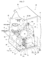
FIG. 2 is a perspective view showing the inside of the electrolysis water-making apparatus according to the first embodiment of the present invention. -
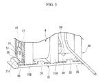
FIG. 3 is a rear perspective view showing a portion of the inside of the electrolysis water-making apparatus according to the first embodiment of the present invention. -
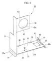
FIG. 4 is a perspective view showing a bracket of the electrolysis water-making apparatus according to the first embodiment of the present invention. -
FIG. 5 is a perspective view showing a state in which the bracket of the electrolysis water-making apparatus according to the first embodiment of the present invention is removed from a casing. -
FIG. 6 is a perspective view showing a variant of the electrolysis water-making apparatus according to the first embodiment of the present invention. -
FIG. 7 is a view schematically showing a configuration of an electrolysis water-making apparatus according to a second embodiment of the present invention' -
FIG. 8 is a perspective view showing the inside of the electrolysis water-making apparatus according to the second embodiment of the present invention. -
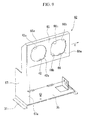
FIG. 9 is a perspective view showing a bracket of the electrolysis water-making apparatus according to the second embodiment of the present invention. - Hereinafter, embodiments of an electrolysis water-making apparatus according to the present invention will be described with reference to the accompanying drawings.
Here, a raw material solution including chlorine ions, which is a raw material of electrolysis water, is water including chlorine ions such as a sodium chloride solution, a hydrochloric acid solution, or the like.
The electrolysis water-making apparatus according to the present invention perform electrolysis on such a raw material solution. Chlorine gas is generated by an action of electrolytic oxidation by the electrolysis. The chlorine gas generated by the action of electrolytic oxidation is dissolved in water to generate hypochlorious acid in water. - As shown in
FIG. 1 , an electrolysis water-makingapparatus 1A includes araw water line 3A through which raw water (dilution water) flowing from araw water inlet 2 flows, anelectrolyzed products line 3B configured to supply a hydrochloric acid solution, which is a raw material solution, into anelectrolytic cell 4 of the electrolysis water-makingapparatus 1A and extract the electrolyzed products electrolytically treated in theelectrolytic cell 4, and an electrolysiswater supply line 3C configured to dilute the electrolyzed products generated in the electrolyzedproducts line 3B and supply the electrolysis water, which is finally sterilized water, into anejection port 5.
As shown inFIG. 2 , thelines 3A to 3C are accommodated in a substantiallyrectangular casing 20 except for astorage tank 9. For this reason, an opening/shuttingdoor 21 installed at a side surface of thecasing 20 is opened, and the parts can be appropriately repaired and inspected. - The
raw water line 3A includes a strainer (not shown), an on-off valve (solenoid valve) 7 configured to open/close a flow of raw water at a downstream side of the strainer, apressure switch 8 configured to control a pressure of raw water flowing inside a piping at a downstream side of the solenoid valve 7, and a check valve (not shown) configured to prevent backward flow of the raw water, which are installed at awater supply line 6 through which the raw water flowing from theraw water inlet 2 flows. - In the
water supply line 6, theraw water inlet 2 and theejection port 5 of the electrolysis water are attached to an intermediate section in a vertical direction of aside plate 22 of thecasing 20. - The
electrolyzed products line 3B includes thestorage tank 9 configured to store the hydrochloric acid solution, a raw materialsolution feed pump 10 configured to discharge the hydrochloric acid solution from thestorage tank 9 and pump the hydrochloric acid solution toward theelectrolytic cell 4, and theelectrolytic cell 4 configured to perform electrolysis on the pumped hydrochloric acid solution. Thestorage tank 9 and thepump 10 are connected by afirst piping 11. Theelectrolytic cell 4 and the electrolysiswater supply line 3C are connected by asecond piping 12. Further, thepump 10 and theelectrolytic cell 4 are connected by athird piping 13. - All of the first to
third pipings electrolytic cell 4, and power is supplied from an electrolysis power supply. - Disposition of the members is as follows. A connecting
location 11a of thefirst piping 11 and thepump 10 is disposed over thestorage tank 9. Thepump 10 is disposed over theelectrolytic cell 4. A connectinglocation 12a of the electrolysiswater supply line 3C and thesecond piping 12 is disposed over a connectinglocation 12b of theelectrolytic cell 4 and thesecond piping 12. Then, thepump 10 and theelectrolytic cell 4 are integrally attached to abracket 30 to be detachably installed in thecasing 20. - The
electrolytic cell 4 is configured such that a unit cell configured to electrolyze the hydrochloric acid solution is formed in achassis 14. Thechassis 14 includesside plates body 16. Thechassis 14 is formed of a plastic such as polyvinyl chloride, polycarbonate, polyacrylate acrylate, or the like. - The
side plates inlet 25a configured to introduce the hydrochloric acid solution is formed under theside plate 15A. Anoutlet 25b (the connectinglocation 12a) configured to extract the electrolyzed products, which are electrolytically treated, is formed over theside plate 15B. - The
body 16 is a member having a cylindrical shape. A plurality of electrode plates disposed in a direction perpendicular to a center axis of thebody 16 are arranged in an inner space of thebody 16. In thebody 16, the raw material solution in theelectrolytic cell 4 is electrolyzed by a current flowing through the plurality of electrode plates. Theside plates body 16, and fixed to thebody 16. - The raw material
solution feed pump 10 is constituted by apump body 17 having a disc shape, and anactuator 18. Thepump body 17 accommodates a tube and a rotor configured to rotate a roller that crushes the tube, and moves the hydrochloric acid solution in the tube by rotation of the rotor. Theactuator 18 drives the rotor. Aninlet 17a (the connectinglocation 11a) configured to suction the hydrochloric acid solution and anoutput port 17b configured to pump the hydrochloric acid solution toward theelectrolytic cell 4 are formed under thepump body 17. - The
electrolytic cell 4 and thepump 10 are installed in thecasing 20 having the above-mentioned positional relationship, integrally attached to thebracket 30, and detachably fixed to aninstallation base 31 in thecasing 20 via thebracket 30. Thebracket 30 facilitates the replacement process when appropriate replacement is needed due to lifespan of the electrode plate of theelectrolytic cell 4 and deterioration of the tube or a diaphragm of thepump 10 or lifespan of the motor. - The
installation base 31 is a substantially rectangular base frame having a predetermined thickness. Theinstallation base 31 is fixed to the opening/shuttingdoor 21 side (hereinafter referred to as a side near the casing) of thecasing 20 by welding. - As shown in
FIG. 3 , amale screw hole 39 into which abolt 50 can be screwed is formed at a side of theinstallation base 31 near the case (a depth side of the drawing). Catchingplates installation base 31 and configured to sandwich abottom plate section 35 of thebracket 30 are formed at an edge of a depth side (a near side of the drawing) and an edge of a side portion of thecasing 20. - As shown in
FIG. 4 , thebracket 30 is formed by bending a plate formed of a metal or plastic. Thebracket 30 includes thebottom plate section 35 fixed to an upper surface of theinstallation base 31 and attachable to theelectrolytic cell 4 shown inFIG. 2 , aside plate section 37 vertically standing up from anedge 35a of a side portion of thebottom plate section 35, and apump attachment section 38 extending from a side edge in a vertical direction forming theside plate section 37 in a direction perpendicular to theside plate section 37. - A through
hole 33 into which thebolt 50 can be inserted is formed at thebottom plate section 35 of thebracket 30 to match a position of themale screw hole 39 formed in theinstallation base 31. Thebottom plate section 35 having the throughhole 33 is inserted into lower sides of the catchingplates installation base 31, and thebracket 30 is detachably attached to theinstallation base 31 by screwing thebolt 50 into the throughhole 33 and themale screw hole 39. In addition, arigid wall 40 of the electrolytic cell at which theelectrolytic cell 4 shown inFIG. 2 is installed is formed at thebottom plate section 35 to approach aside edge 35c opposite to theside edge 35a at which theside plate section 37 is formed. - The
rigid wall 40 of the electrolytic cell is a wall section vertically standing up from thebottom plate section 35. Therigid wall 40 of the electrolytic cell has throughholes electrolytic cell 4. On the other hand, inFIG. 3 , male screw holes (not shown) into whichbolts holes side plate 15B of theelectrolytic cell 4. - As shown in
FIGS. 2 and4 , thepump attachment section 38 is formed over theside plate section 37 of the bracket. Theside plate section 37 is configured such that thepump 10 attached to thepump attachment section 38 has a height which is capable of being disposed over thestorage tank 9 and theelectrolytic cell 4. - The
pump attachment section 38 is formed to extend from an upper edge of theside plate section 37 along an inner wall surface of thecasing 20 to be disposed at a side of theinstallation base 31 near the casing. A mountinghole 42 configured to mount thepump 10 is formed inside thepump attachment section 38. - A pair of
hooks hole 42. Then, on the other hand, a pair of catching plates (not shown) are snap-fitted to thehooks 42a at a rear side of thepump body 17 of the pump 10 (a side in contact with the pump attachment section 38). As will be described below, thehooks 42a are fitted to the catching plates of thepump 10 to become an angle determining unit of thepump 10. - When the
pump 10 is attached to thebracket 30, first, theactuator 18 is inserted into the mountinghole 42. Here, a pair of recesses (not shown) formed at the rear side of thepump body 17 are inserted to be fitted to the pair ofhooks hole 42. As thehooks pump 10, an angle of thepump 10 with respect to thebracket 30 always becomes a predetermined angle, and thepump 10 is prevented from being pivoted with respect to thebracket 30.
Then, thepump 10 is appropriately fixed by a fastener such as a bolt or a clip (not shown) installed at thepump body 17 and thepump attachment section 38 with thepump attachment section 38 sandwiched therebetween. - As shown in
FIG. 2 , the electrolysiswater supply line 3C constitutes a dilutingunit 26 configured to dilute the electrolyzed products introduced from theelectrolytic cell 4 by the raw water of thewater supply line 6 and generate the electrolysis water. The electrolysiswater supply line 3C is formed at the most downstream side of thewater supply line 6. - As described above, the
water supply line 6, theelectrolytic cell 4, thepump 10, and a portion of thepump 10 side of thefirst piping 11 and the second andthird pipings casing 20. Theelectrolytic cell 4 and thepump 10 are integrally and detachably attached to thebracket 30 to be easily drawn from the opening/shuttingdoor 21 of thecasing 20. Further, thebracket 30 is fixed to theinstallation base 31 in thecasing 20 by thebolt 50. - Next, a method of replacing the
electrolytic cell 4 or thepump 10 of the electrolysis water-makingapparatus 1A or both of them will be described.
First, a power supply of the electrolysis water-makingapparatus 1A is turned OFF, and a flow of the hydrochloric acid solution and raw water is stopped. Then, as shown inFIG. 5 , the opening/shuttingdoor 21 of thecasing 20 is opened, and thebolt 50 fixed to theinstallation base 31 is removed. Accordingly, thebracket 30 can be drawn to a side of theinstallation base 31 near the casing (in a direction of an arrow P). - Then, the
first piping 11 is removed from the connectinglocation 11a of thepump 10 and thefirst piping 11, and the hydrochloric acid solution remaining in thefirst piping 11 is returned to thestorage tank 9 shown inFIG. 2 . - Next, the
second piping 12 is removed from the connectinglocation 12a of the dilutingunit 26 and thesecond piping 12. The removed second piping 12 is maintained in a state in which the mounting hole is directed upward such that the electrolyzed products remaining in thesecond piping 12 do not spill out. - In this state, the
bracket 30 is drawn to oneend side 31b of the installation base 31 (a direction of an arrow P), i.e., to a side near the casing. As thebracket 30 is drawn, theelectrolytic cell 4 and thepump 10 are removed from thecasing 20 by eachbracket 30. Then, thebracket 30 is brought to a place where the process can be done easily and the hydrochloric acid solution or the like can be wasted, and thus, the electrolyzed products in thesecond piping 12 are discarded. After that, thethird piping 13 connecting thepump 10 and theelectrolytic cell 4 is removed from aninlet 17b of thepump 10, and the hydrochloric acid solution remaining in thethird piping 13 is discarded. - When the
pump 10 is replaced with a new one, the fastener installed at thepump attachment section 38 is unfastened to remove thepump 10 from thebracket 30. In addition, when theelectrolytic cell 4 is replaced with a new one, thebolts FIG. 3 are removed to be separated from thebracket 30, appropriately performing the replacement. - When a
new pump 10 orelectrolytic cell 4 is attached, the above-mentioned removal sequence is performed in a reverse sequence. Specifically, as shown inFIG. 5 , outside thecasing 20, theactuator 18 of thepump 10 is inserted into the mounting hole 42 (seeFIG. 4 ) of thepump attachment section 38 and fixed thereto by the fastener. As shown inFIG. 3 , even in theelectrolytic cell 4, theelectrolytic cell 4 is installed at thebottom plate section 35 of thebracket 30 outside thecasing 20, theside plate 15B abuts therigid wall 40 of the electrolytic cell, and thebolts holes side plate 15B. - Next, the
third piping 13 shown inFIG. 5 is connected to theoutput port 17b of thepump 10 and theinlet 25a of theelectrolytic cell 4, and thebracket 30 is installed in thecasing 20. In order to install thebracket 30 at theinstallation base 31 in thecasing 20, an end of thebottom plate section 35 is slid and disposed between an upper surface of theinstallation base 31 and the catchingplates bolt 50 is screwed and securely fixed to themale screw hole 39 of theinstallation base 31 through the throughhole 33. - Then, as the
first piping 11 is connected to theinlet 17a of thepump 10 and simultaneously thesecond piping 12 is connected between theoutlet 25b of theelectrolytic cell 4 and the dilutingunit 26 to close the opening/shuttingdoor 21 of thecasing 20, replacement of thepump 10 or theelectrolytic cell 4 is completed. - As described above, according to the electrolysis water-making
apparatus 1 A in accordance with the embodiment, thebracket 30 can be removed, and thepump 10 and theelectrolytic cell 4 can be removed to the outside of thecasing 20 by eachbracket 30 to perform a discarding process or the like. Accordingly, the process of replacing the inside of thepump 10, theelectrolytic cell 4, and the first tothird pipings pump 10 and theelectrolytic cell 4 can be increased, and water used in the replacement process can be saved. - In addition, even when the first and
second pipings pump 10 and theelectrolytic cell 4 are removed in thecasing 20, the process can be performed with almost no spilling out of the solution. For this reason, time spent cleaning thecasing 20 can be omitted. - Furthermore, as the
bolt 50 of thebracket 30 is removed, thefirst piping 11 is removed from theinlet 17a of thepump 10, and further, thesecond piping 12 is removed from the connectinglocation 12a of the dilutingunit 26, removal of thebracket 30 from thecasing 20 becomes possible, and the process in thecasing 20 can be suppressed to a minimal level. For this reason, the replacement process can be easily performed. In addition, thepump 10 and theelectrolytic cell 4 can be moved while attached to thebracket 30 to a place in which the process can be easily performed. - Further, since a configuration of the
bracket 30 and a structure of theinstallation base 31 to which thebracket 30 is attached are simple, the manufacturing cost of the electrolysis water-makingapparatus 1A can be suppressed to a low level. - Furthermore, since the
casing 20 and thebracket 30 are detachably fixed to one place by thebolt 50, thebracket 30 may be removed by removing onebolt 50 when thebracket 30 is removed from thecasing 20. In addition, onebolt 50 may be screwed when thebracket 30 is mounted on thecasing 20. As described above, process can be simplified and workability can be improved, and part cost can also be saved. Further, the same effect can be obtained even when a fixing unit such as a split pin or a wing nut is employed instead of thebolt 50. - In the embodiment, upon replacement of the
pump 10 and theelectrolytic cell 4, while the first andsecond pipings locations bracket 30 to the outside of thecasing 20, as shown inFIG. 6 , the length of the first andsecond pipings bracket 30 may be configured to be removed to the outside of thecasing 20 in a state in which the first andsecond pipings pump 10 and theelectrolytic cell 4. - As the above-mentioned configuration is provided, the first and
second pipings casing 20, and contamination in thecasing 20 can be avoided even when the solution in the piping overflows upon removal of the pipings. In addition, when a sheet or a plate is prepared at the outside of thecasing 20, the removal process of the first andsecond pipings - In addition, a length of the first and
second pipings second pipings bracket 30 is drawn in front of thecasing 20 and thebracket 30 and thecasing 20 are disposed in parallel such that a front edge of thecasing 20 is in contact with a rear edge of the bracket 30 (a side near a solid line is "a front end" and an opposite side is "a rear end" when seen in a direction of the arrow P). - Next, a second embodiment of the present invention will be described. In the embodiment, like elements of the first embodiment are designated by like reference numerals, and description thereof will not be repeated.
- As shown in
FIG. 7 , an electrolysis water-makingapparatus 1B according to the second embodiment includes ahydrochloric acid line 3D in addition to the configuration of the electrolysis water-makingapparatus 1A according to the first embodiment. Thehydrochloric acid line 3D has a starting end branched from theraw water line 3A and a terminating end joined with an upstream side of theelectrolytic cell 4 in an electrolyzedproducts generating line 3B. Then, thehydrochloric acid line 3D includes a dilutionwater feed pump 60. - The dilution
water feed pump 60 extracts raw water from theraw water line 3A, and mixes the raw water with a hydrochloric acid solution before performing electrolysis. The dilutionwater feed pump 60 can appropriately adjust a concentration of the hydrochloric acid solution supplied into theelectrolytic cell 4. - As shown in
FIG. 8 , this embodiment is distinguished from the electrolysis water-makingapparatus 1A according to the first embodiment in that abracket 62 is configured to hold the dilutionwater feed pump 60 in addition to theelectrolytic cell 4 and the raw materialsolution feed pump 10. - The dilution
water feed pump 60 suctions dilution water from thewater supply line 6, and the dilution water is delivered into thethird piping 13 connected to theinlet 25a of theelectrolytic cell 4. The dilutionwater feed pump 60 has the same configuration as the raw materialsolution feed pump 10, and includes apump body 63 having a disc shape, and anactuator 64. Thepump body 63 accommodates a tube and a rotor configured to rotate a roller that crushes the tube, and moves the dilution water in the tube by rotation of the rotor. Theactuator 64 drives the rotor. Aninlet 63a configured to suction the dilution water and anoutput port 63b configured to pump the dilution water toward thethird piping 13 are formed under thepump body 63. - A
fourth piping 70 is connected between theinlet 63a of thepump 60 and thewater supply line 6. Afifth piping 71 is connected between theoutput port 63b and thethird piping 13. - As shown in
FIG. 9 , a mountinghole 42 configured to hold thepump 10 at apump attachment section 65 and a mountinghole 66 configured to hold thepump 60 are formed in thebracket 62. In addition, thebracket 62 includes a fastener such as a bolt or a clip (not shown) configured to hold thepumps - A pair of
hooks hooks hole 66. On the other hand, a pair of catching plates (not shown) snap-fitted to thehooks 66a or thehooks 66b protrude from a rear side of thepump body 63 of thepump 60 shown inFIG. 8 (a side in contact with the pump attachment section 65). Thehooks 66a or thehooks 66b are fitted to the catching plates of thepump 60 to become an angle determining unit of thepump 60. - When the
pump 60 is attached to thebracket 62, first, theactuator 64 is inserted into the mountinghole 66. Here, the pair of catching plates (not shown) formed at the rear side of thepump body 63 are inserted to be fitted to the pair ofhooks hole 66. Accordingly, an angle of thepump 60 with respect to thebracket 62 always becomes a certain angle, and thepump 60 is prevented from being pivoted with respect to thebracket 62. - Then, the dilution
water feed pump 60 is appropriately fixed by the fastener such as a bolt or a clip (not shown) installed at thepump body 63 and thepump attachment section 65 with thepump attachment section 65 sandwiched therebetween.
In addition, in the above-mentioned example, while the pair of catching plates (not shown) are fitted to the pair ofhooks hooks - The pair of
hooks hooks hooks pump 60 are fitted to thehooks hooks pump 60 is rotated 90° counterclockwise (counterclockwise when seen from a side near the casing of theinstallation base 31 or a side of the pump body 63) and attached thereto. - In this state, the
inlet 63a and theoutput port 63b shown inFIG. 8 are directed in a direction of an arrow X shown inFIG. 9 . For this reason, workability can be further improved with no interference with theelectrolytic cell 4 when the process of connecting or separating thefourth piping 70 and thefifth piping 71 to and from each other is performed. - In addition, the
side plate section 67 of thebracket 62 is a wall section standing up from a side edge of thebottom plate section 35. Theside plate section 67 includes abent section 67a configured to prevent theside plate section 67 from being bent due to weights of thepumps pumps pump attachment section 65.
In addition, abent section 65a is also formed at an upper end of thepump attachment section 65. Thebent section 65a prevents thepump attachment section 65 from being bent due to the weights of thepumps pumps - As shown in
FIG. 8 , when theelectrolytic cell 4, the raw materialsolution feed pump 10, and the dilutionwater feed pump 60 of the electrolysis water-makingapparatus 1B are replaced with new ones, thebolt 50 of thebracket 62 is removed and thebracket 62 is in an extractable state. - The
first piping 11 is removed from the connectinglocation 11a to return the hydrochloric acid solution to thestorage tank 9. After that, thesecond piping 12 and thefourth piping 70 are removed from the connectinglocation 12a of the dilutingunit 26 side and the connecting location of thewater supply line 6 side, respectively. The second andfourth pipings - In this state, the
bracket 62 by which theelectrolytic cell 4 and thepumps casing 20 to discard the chloride solution and electrolyzed products in the piping. Further, the third andfifth pipings bracket 62.
Then, the third andfifth pipings bracket 62 is installed at and fixed to theinstallation base 31 in thecasing 20. Next, the first, second andfourth pipings door 21 of thecasing 20, completing the replacement of the member. - As described above, according to the electrolysis water-making
apparatus 1B in accordance with the second embodiment, even when thefifth piping 71 and the dilutionwater feed pump 60 are connected to thethird piping 13 configured to deliver the hydrochloric acid solution to theelectrolytic cell 4 and connection relation of the piping is complicated, only a minimum piping connected to thestorage tank 9 and thewater supply line 6 is removed, and theelectrolytic cell 4 and thepumps casing 20 by thebracket 62, enabling the replacement process. - Then, the
electrolytic cell 4 and thepumps casing 20 by thebracket 62. For this reason, since removal and waste solution treatment of the piping connecting the respective members become easy and are completed with almost no contamination of the inside of thecasing 20 due to the chloride solution and electrolyzed products, working efficiency can be increased. - In addition, similar to the effect obtained by the electrolysis water-making
apparatus 1A according to the first embodiment, since the configuration of thebracket 62 becomes simple, manufacturing cost of the electrolysis water-makingapparatus 1B can be suppressed. - Further, as a plurality of angle determining means such as the pair of
hooks hooks water feed pump 60 can be attached while varying an angle with respect to thebracket 62, and thus a degree of freedom of layout of the piping to be connected to the dilutionwater feed pump 60 is increased to improve workability of connection and removal. - According to the electrolysis water-making apparatus in accordance with the present invention, after the electrolytic cell and the raw material solution feed pump are integrally removed by the bracket to be moved to the outside of the casing, treatment of the solution in the electrolytic cell or the raw material solution feed pump is performed. Accordingly, in the replacement of the electrolytic cell or the raw material solution feed pump, the process of replacing the inside of the electrolytic cell by water can be omitted, and working efficiency of the replacement can be increased.
-
- 1A, 1B
- electrolysis water-making apparatus
- 4
- electrolytic cell
- 9
- storage tank
- 10
- raw material solution feed pump
- 11
- first piping
- 11a
- connecting location
- 12
- second piping
- 12a
- connecting location
- 20
- casing
- 26
- diluting unit
- 30
- bracket
- 50
- bolt
- 60
- dilution water feed pump
- 62
- bracket
- 66a
- hook
- 66b
- hook
Claims (8)
- An electrolysis water-making apparatus comprising:a casing;an electrolytic cell installed in the casing and configured to perform electrolysis on a raw material solution;a raw material solution feed pump configured to pump the raw material solution to the electrolytic cell; anda diluting unit configured to dilute electrolyzed products extracted from the electrolytic cell with dilution water; anda bracket configured to integrally attach the electrolytic cell and the raw material solution feed pump, and configured to be detachably fixed to the inside of the casing in a state in which the electrolytic cell and the raw material solution feed pump are attached thereto.
- The electrolysis water-making apparatus according to claim 1, wherein
a first piping is connected between the raw material solution feed pump and a storage tank configured to store the raw material solution, and
a connecting location of the first piping and the raw material solution feed pump is disposed over the storage tank. - The electrolysis water-making apparatus according to claim 1 or 2, wherein
a second piping is connected between the electrolytic cell and the diluting unit, and
a connecting location of the second piping and the diluting unit is disposed over a connecting location of the second piping and the electrolytic cell. - The electrolysis water-making apparatus according to claim 2 or 3, wherein the first and second pipings are formed of a flexible pipe.
- The electrolysis water-making apparatus according to claim 4, wherein the first and second pipings have lengths such that the bracket is extractable to the outside of the casing in a state in which the raw material solution feed pump, the electrolytic cell, and the diluting unit are connected to the respective connecting locations.
- The electrolysis water-making apparatus according to any one of claims 1 to 5, further comprising a dilution water feed pump configured to pump dilution water to the electrolytic cell,
wherein the dilution water feed pump is detachably attached to the bracket. - The electrolysis water-making apparatus according to claim 6, wherein the dilution water feed pump is detachably attached to the bracket with a variable angle.
- The electrolysis water-making apparatus according to any one of claims 1 to 7, wherein the casing and the bracket are detachably fixed to one place.
Applications Claiming Priority (2)
| Application Number | Priority Date | Filing Date | Title |
|---|---|---|---|
| JP2010124879A JP5156792B2 (en) | 2010-05-31 | 2010-05-31 | Electrolyzed water production equipment |
| PCT/JP2011/061641 WO2011152228A1 (en) | 2010-05-31 | 2011-05-20 | Electrolyzed water production apparatus |
Publications (3)
| Publication Number | Publication Date |
|---|---|
| EP2578540A1 true EP2578540A1 (en) | 2013-04-10 |
| EP2578540A4 EP2578540A4 (en) | 2017-02-08 |
| EP2578540B1 EP2578540B1 (en) | 2020-04-01 |
Family
ID=45066607
Family Applications (1)
| Application Number | Title | Priority Date | Filing Date |
|---|---|---|---|
| EP11789637.3A Active EP2578540B1 (en) | 2010-05-31 | 2011-05-20 | Electrolyzed water production apparatus |
Country Status (7)
| Country | Link |
|---|---|
| US (1) | US9139919B2 (en) |
| EP (1) | EP2578540B1 (en) |
| JP (1) | JP5156792B2 (en) |
| KR (2) | KR101549623B1 (en) |
| CN (1) | CN102917982B (en) |
| TW (1) | TWI461574B (en) |
| WO (1) | WO2011152228A1 (en) |
Cited By (1)
| Publication number | Priority date | Publication date | Assignee | Title |
|---|---|---|---|---|
| EP2578541A4 (en) * | 2010-05-31 | 2016-10-19 | Morinaga Milk Industry Co Ltd | DEVICE FOR PRODUCING ELECTROLYSED WATER |
Families Citing this family (5)
| Publication number | Priority date | Publication date | Assignee | Title |
|---|---|---|---|---|
| TWI485291B (en) * | 2012-09-28 | 2015-05-21 | Morinaga Milk Industry Co Ltd | Electrolysis water-making apparatus, electrolysis water-making method, and electrolytic cell |
| JP5845293B2 (en) * | 2014-01-22 | 2016-01-20 | 株式会社日本トリム | Electrolyzed water generator |
| JP6853049B2 (en) * | 2017-01-18 | 2021-03-31 | 株式会社日本トリム | Electrolyzed water generator |
| JP6870992B2 (en) * | 2017-01-18 | 2021-05-12 | 株式会社日本トリム | Electrolyzed water generator |
| JP7483481B2 (en) * | 2020-04-27 | 2024-05-15 | 森永乳業株式会社 | Electrolyzed water production device and method for producing electrolyzed water |
Family Cites Families (17)
| Publication number | Priority date | Publication date | Assignee | Title |
|---|---|---|---|---|
| JPH06206074A (en) * | 1992-09-04 | 1994-07-26 | Tatsuo Okazaki | Method and apparatus for producing sterilizing water |
| JPH0699177A (en) | 1992-09-17 | 1994-04-12 | Konica Corp | Water treatment device |
| JPH11169856A (en) | 1996-06-04 | 1999-06-29 | Mizu Kk | Electrolytic water producing device |
| JP3761267B2 (en) * | 1996-12-18 | 2006-03-29 | 松下エコシステムズ株式会社 | Electrolyzed water generator |
| CN1136153C (en) | 1997-10-23 | 2004-01-28 | 星崎电机株式会社 | Electrolyzed water production apparatus |
| JPH11235378A (en) * | 1998-02-19 | 1999-08-31 | Morinaga Milk Ind Co Ltd | Electrolytic water hand washer |
| JP3494570B2 (en) * | 1998-03-09 | 2004-02-09 | ホシザキ電機株式会社 | Electrolyzed water generator |
| JP3951156B2 (en) * | 1998-04-10 | 2007-08-01 | 株式会社オメガ | Method and apparatus for supplying sterilized cleaning water |
| SG91247A1 (en) | 1998-06-16 | 2002-09-17 | Hoshizaki Electric Co Ltd | Electrolyed water production apparatus |
| JP3571258B2 (en) | 1999-08-31 | 2004-09-29 | アマノ株式会社 | Electrolyzed water generator |
| JP3957476B2 (en) | 2001-05-28 | 2007-08-15 | 三洋電機株式会社 | Water treatment equipment |
| US6656334B2 (en) * | 2001-07-23 | 2003-12-02 | Skydon Corp. | Modified electrolysis cell and a housing for the same |
| JP2005035670A (en) * | 2003-07-02 | 2005-02-10 | Hoshizaki Electric Co Ltd | Structure for mounting functional instrument on housing |
| US7326325B2 (en) * | 2003-09-19 | 2008-02-05 | Siemens Water Technologies Holding Corp. | Apparatus and method for connecting water treatment devices |
| JP4277317B2 (en) * | 2004-09-29 | 2009-06-10 | Toto株式会社 | Electrolyzed water generator |
| JP5227710B2 (en) * | 2008-09-19 | 2013-07-03 | 三洋電機株式会社 | Electrolyzed water generator and sterilization system |
| JP5305770B2 (en) * | 2008-07-25 | 2013-10-02 | 三洋電機株式会社 | Air sanitizer |
-
2010
- 2010-05-31 JP JP2010124879A patent/JP5156792B2/en active Active
-
2011
- 2011-05-20 KR KR1020127032751A patent/KR101549623B1/en active Active
- 2011-05-20 WO PCT/JP2011/061641 patent/WO2011152228A1/en not_active Ceased
- 2011-05-20 KR KR1020157007727A patent/KR20150039880A/en not_active Withdrawn
- 2011-05-20 CN CN201180026595.2A patent/CN102917982B/en active Active
- 2011-05-20 US US13/700,219 patent/US9139919B2/en active Active
- 2011-05-20 EP EP11789637.3A patent/EP2578540B1/en active Active
- 2011-05-24 TW TW100118107A patent/TWI461574B/en active
Non-Patent Citations (1)
| Title |
|---|
| See references of WO2011152228A1 * |
Cited By (2)
| Publication number | Priority date | Publication date | Assignee | Title |
|---|---|---|---|---|
| EP2578541A4 (en) * | 2010-05-31 | 2016-10-19 | Morinaga Milk Industry Co Ltd | DEVICE FOR PRODUCING ELECTROLYSED WATER |
| US9643863B2 (en) | 2010-05-31 | 2017-05-09 | Morinaga Milk Industry Co., Ltd. | Electrolysis water-making apparatus |
Also Published As
| Publication number | Publication date |
|---|---|
| JP2011251211A (en) | 2011-12-15 |
| KR101549623B1 (en) | 2015-09-02 |
| US9139919B2 (en) | 2015-09-22 |
| JP5156792B2 (en) | 2013-03-06 |
| EP2578540B1 (en) | 2020-04-01 |
| US20130068612A1 (en) | 2013-03-21 |
| CN102917982A (en) | 2013-02-06 |
| EP2578540A4 (en) | 2017-02-08 |
| KR20130018331A (en) | 2013-02-20 |
| CN102917982B (en) | 2014-04-30 |
| TW201202483A (en) | 2012-01-16 |
| KR20150039880A (en) | 2015-04-13 |
| TWI461574B (en) | 2014-11-21 |
| WO2011152228A1 (en) | 2011-12-08 |
| KR101549623B9 (en) | 2025-01-08 |
Similar Documents
| Publication | Publication Date | Title |
|---|---|---|
| EP2578540B1 (en) | Electrolyzed water production apparatus | |
| US9643863B2 (en) | Electrolysis water-making apparatus | |
| JP4020787B2 (en) | Water treatment equipment | |
| EP2872676B9 (en) | Electrolytic cell configured for rapid service, removal and replacement | |
| CN102439200A (en) | Disposable outer box for electrolytic cells | |
| TW201300577A (en) | Electrolyzed water generator | |
| KR101704615B1 (en) | Plating Equipment | |
| HK1180670A (en) | Electrolyzed water production apparatus | |
| HK1180670B (en) | Electrolyzed water production apparatus | |
| JP2009013600A (en) | Cabinet and water supply apparatus provided with the cabinet | |
| HK1180669A (en) | Electrolyzed water production device | |
| KR101642662B1 (en) | Feedwater pump with electrolyzer | |
| JP3089465B2 (en) | Electrolytic testing machine | |
| JP7598848B2 (en) | Electrolyzed water generator | |
| US20050067275A1 (en) | Water treatment apparatus that can reduce water treatment time | |
| CN213171794U (en) | Chemical nickel plating waste water treatment equipment | |
| CN210458421U (en) | Coarsening electrolysis regeneration system capable of automatically replacing electrolyte | |
| CN211198892U (en) | Full-automatic industrial circulating water electrochemical treatment device | |
| JP3696334B2 (en) | Electrolytic tank hazardous gas treatment equipment | |
| CN211471622U (en) | Water curtain type workpiece processing device and workpiece processing production line with same | |
| JP2005279519A (en) | Apparatus for producing electrolytic water | |
| CN206051719U (en) | It is a kind of to make quiet formula wastewater treatment equipment | |
| JPH0562573U (en) | Diaphragm electrode device |
Legal Events
| Date | Code | Title | Description |
|---|---|---|---|
| PUAI | Public reference made under article 153(3) epc to a published international application that has entered the european phase |
Free format text: ORIGINAL CODE: 0009012 |
|
| 17P | Request for examination filed |
Effective date: 20121227 |
|
| AK | Designated contracting states |
Kind code of ref document: A1 Designated state(s): AL AT BE BG CH CY CZ DE DK EE ES FI FR GB GR HR HU IE IS IT LI LT LU LV MC MK MT NL NO PL PT RO RS SE SI SK SM TR |
|
| DAX | Request for extension of the european patent (deleted) | ||
| REG | Reference to a national code |
Ref country code: HK Ref legal event code: DE Ref document number: 1180670 Country of ref document: HK |
|
| REG | Reference to a national code |
Ref country code: DE Ref legal event code: R079 Ref document number: 602011066016 Country of ref document: DE Free format text: PREVIOUS MAIN CLASS: C02F0001460000 Ipc: C02F0001461000 |
|
| RIC1 | Information provided on ipc code assigned before grant |
Ipc: C02F 1/461 20060101AFI20161222BHEP |
|
| RA4 | Supplementary search report drawn up and despatched (corrected) |
Effective date: 20170109 |
|
| GRAP | Despatch of communication of intention to grant a patent |
Free format text: ORIGINAL CODE: EPIDOSNIGR1 |
|
| STAA | Information on the status of an ep patent application or granted ep patent |
Free format text: STATUS: GRANT OF PATENT IS INTENDED |
|
| GRAJ | Information related to disapproval of communication of intention to grant by the applicant or resumption of examination proceedings by the epo deleted |
Free format text: ORIGINAL CODE: EPIDOSDIGR1 |
|
| GRAP | Despatch of communication of intention to grant a patent |
Free format text: ORIGINAL CODE: EPIDOSNIGR1 |
|
| INTG | Intention to grant announced |
Effective date: 20191004 |
|
| INTG | Intention to grant announced |
Effective date: 20191015 |
|
| GRAS | Grant fee paid |
Free format text: ORIGINAL CODE: EPIDOSNIGR3 |
|
| GRAA | (expected) grant |
Free format text: ORIGINAL CODE: 0009210 |
|
| STAA | Information on the status of an ep patent application or granted ep patent |
Free format text: STATUS: THE PATENT HAS BEEN GRANTED |
|
| AK | Designated contracting states |
Kind code of ref document: B1 Designated state(s): AL AT BE BG CH CY CZ DE DK EE ES FI FR GB GR HR HU IE IS IT LI LT LU LV MC MK MT NL NO PL PT RO RS SE SI SK SM TR |
|
| REG | Reference to a national code |
Ref country code: GB Ref legal event code: FG4D |
|
| REG | Reference to a national code |
Ref country code: CH Ref legal event code: EP Ref country code: AT Ref legal event code: REF Ref document number: 1251147 Country of ref document: AT Kind code of ref document: T Effective date: 20200415 |
|
| REG | Reference to a national code |
Ref country code: DE Ref legal event code: R096 Ref document number: 602011066016 Country of ref document: DE |
|
| REG | Reference to a national code |
Ref country code: IE Ref legal event code: FG4D |
|
| PG25 | Lapsed in a contracting state [announced via postgrant information from national office to epo] |
Ref country code: BG Free format text: LAPSE BECAUSE OF FAILURE TO SUBMIT A TRANSLATION OF THE DESCRIPTION OR TO PAY THE FEE WITHIN THE PRESCRIBED TIME-LIMIT Effective date: 20200701 |
|
| PGFP | Annual fee paid to national office [announced via postgrant information from national office to epo] |
Ref country code: GB Payment date: 20200527 Year of fee payment: 10 |
|
| REG | Reference to a national code |
Ref country code: NL Ref legal event code: MP Effective date: 20200401 |
|
| REG | Reference to a national code |
Ref country code: LT Ref legal event code: MG4D |
|
| PG25 | Lapsed in a contracting state [announced via postgrant information from national office to epo] |
Ref country code: CZ Free format text: LAPSE BECAUSE OF FAILURE TO SUBMIT A TRANSLATION OF THE DESCRIPTION OR TO PAY THE FEE WITHIN THE PRESCRIBED TIME-LIMIT Effective date: 20200401 Ref country code: IS Free format text: LAPSE BECAUSE OF FAILURE TO SUBMIT A TRANSLATION OF THE DESCRIPTION OR TO PAY THE FEE WITHIN THE PRESCRIBED TIME-LIMIT Effective date: 20200801 Ref country code: PT Free format text: LAPSE BECAUSE OF FAILURE TO SUBMIT A TRANSLATION OF THE DESCRIPTION OR TO PAY THE FEE WITHIN THE PRESCRIBED TIME-LIMIT Effective date: 20200817 Ref country code: LT Free format text: LAPSE BECAUSE OF FAILURE TO SUBMIT A TRANSLATION OF THE DESCRIPTION OR TO PAY THE FEE WITHIN THE PRESCRIBED TIME-LIMIT Effective date: 20200401 Ref country code: NL Free format text: LAPSE BECAUSE OF FAILURE TO SUBMIT A TRANSLATION OF THE DESCRIPTION OR TO PAY THE FEE WITHIN THE PRESCRIBED TIME-LIMIT Effective date: 20200401 Ref country code: SE Free format text: LAPSE BECAUSE OF FAILURE TO SUBMIT A TRANSLATION OF THE DESCRIPTION OR TO PAY THE FEE WITHIN THE PRESCRIBED TIME-LIMIT Effective date: 20200401 Ref country code: GR Free format text: LAPSE BECAUSE OF FAILURE TO SUBMIT A TRANSLATION OF THE DESCRIPTION OR TO PAY THE FEE WITHIN THE PRESCRIBED TIME-LIMIT Effective date: 20200702 Ref country code: FI Free format text: LAPSE BECAUSE OF FAILURE TO SUBMIT A TRANSLATION OF THE DESCRIPTION OR TO PAY THE FEE WITHIN THE PRESCRIBED TIME-LIMIT Effective date: 20200401 Ref country code: NO Free format text: LAPSE BECAUSE OF FAILURE TO SUBMIT A TRANSLATION OF THE DESCRIPTION OR TO PAY THE FEE WITHIN THE PRESCRIBED TIME-LIMIT Effective date: 20200701 |
|
| REG | Reference to a national code |
Ref country code: AT Ref legal event code: MK05 Ref document number: 1251147 Country of ref document: AT Kind code of ref document: T Effective date: 20200401 |
|
| PG25 | Lapsed in a contracting state [announced via postgrant information from national office to epo] |
Ref country code: LV Free format text: LAPSE BECAUSE OF FAILURE TO SUBMIT A TRANSLATION OF THE DESCRIPTION OR TO PAY THE FEE WITHIN THE PRESCRIBED TIME-LIMIT Effective date: 20200401 Ref country code: HR Free format text: LAPSE BECAUSE OF FAILURE TO SUBMIT A TRANSLATION OF THE DESCRIPTION OR TO PAY THE FEE WITHIN THE PRESCRIBED TIME-LIMIT Effective date: 20200401 Ref country code: RS Free format text: LAPSE BECAUSE OF FAILURE TO SUBMIT A TRANSLATION OF THE DESCRIPTION OR TO PAY THE FEE WITHIN THE PRESCRIBED TIME-LIMIT Effective date: 20200401 |
|
| REG | Reference to a national code |
Ref country code: DE Ref legal event code: R119 Ref document number: 602011066016 Country of ref document: DE |
|
| PG25 | Lapsed in a contracting state [announced via postgrant information from national office to epo] |
Ref country code: AL Free format text: LAPSE BECAUSE OF FAILURE TO SUBMIT A TRANSLATION OF THE DESCRIPTION OR TO PAY THE FEE WITHIN THE PRESCRIBED TIME-LIMIT Effective date: 20200401 |
|
| PG25 | Lapsed in a contracting state [announced via postgrant information from national office to epo] |
Ref country code: EE Free format text: LAPSE BECAUSE OF FAILURE TO SUBMIT A TRANSLATION OF THE DESCRIPTION OR TO PAY THE FEE WITHIN THE PRESCRIBED TIME-LIMIT Effective date: 20200401 Ref country code: AT Free format text: LAPSE BECAUSE OF FAILURE TO SUBMIT A TRANSLATION OF THE DESCRIPTION OR TO PAY THE FEE WITHIN THE PRESCRIBED TIME-LIMIT Effective date: 20200401 Ref country code: ES Free format text: LAPSE BECAUSE OF FAILURE TO SUBMIT A TRANSLATION OF THE DESCRIPTION OR TO PAY THE FEE WITHIN THE PRESCRIBED TIME-LIMIT Effective date: 20200401 Ref country code: CH Free format text: LAPSE BECAUSE OF NON-PAYMENT OF DUE FEES Effective date: 20200531 Ref country code: RO Free format text: LAPSE BECAUSE OF FAILURE TO SUBMIT A TRANSLATION OF THE DESCRIPTION OR TO PAY THE FEE WITHIN THE PRESCRIBED TIME-LIMIT Effective date: 20200401 Ref country code: MC Free format text: LAPSE BECAUSE OF FAILURE TO SUBMIT A TRANSLATION OF THE DESCRIPTION OR TO PAY THE FEE WITHIN THE PRESCRIBED TIME-LIMIT Effective date: 20200401 Ref country code: SM Free format text: LAPSE BECAUSE OF FAILURE TO SUBMIT A TRANSLATION OF THE DESCRIPTION OR TO PAY THE FEE WITHIN THE PRESCRIBED TIME-LIMIT Effective date: 20200401 Ref country code: IT Free format text: LAPSE BECAUSE OF FAILURE TO SUBMIT A TRANSLATION OF THE DESCRIPTION OR TO PAY THE FEE WITHIN THE PRESCRIBED TIME-LIMIT Effective date: 20200401 Ref country code: LI Free format text: LAPSE BECAUSE OF NON-PAYMENT OF DUE FEES Effective date: 20200531 Ref country code: DK Free format text: LAPSE BECAUSE OF FAILURE TO SUBMIT A TRANSLATION OF THE DESCRIPTION OR TO PAY THE FEE WITHIN THE PRESCRIBED TIME-LIMIT Effective date: 20200401 |
|
| PLBE | No opposition filed within time limit |
Free format text: ORIGINAL CODE: 0009261 |
|
| STAA | Information on the status of an ep patent application or granted ep patent |
Free format text: STATUS: NO OPPOSITION FILED WITHIN TIME LIMIT |
|
| PG25 | Lapsed in a contracting state [announced via postgrant information from national office to epo] |
Ref country code: SK Free format text: LAPSE BECAUSE OF FAILURE TO SUBMIT A TRANSLATION OF THE DESCRIPTION OR TO PAY THE FEE WITHIN THE PRESCRIBED TIME-LIMIT Effective date: 20200401 Ref country code: PL Free format text: LAPSE BECAUSE OF FAILURE TO SUBMIT A TRANSLATION OF THE DESCRIPTION OR TO PAY THE FEE WITHIN THE PRESCRIBED TIME-LIMIT Effective date: 20200401 |
|
| 26N | No opposition filed |
Effective date: 20210112 |
|
| REG | Reference to a national code |
Ref country code: BE Ref legal event code: MM Effective date: 20200531 |
|
| PG25 | Lapsed in a contracting state [announced via postgrant information from national office to epo] |
Ref country code: LU Free format text: LAPSE BECAUSE OF NON-PAYMENT OF DUE FEES Effective date: 20200520 |
|
| PG25 | Lapsed in a contracting state [announced via postgrant information from national office to epo] |
Ref country code: FR Free format text: LAPSE BECAUSE OF NON-PAYMENT OF DUE FEES Effective date: 20200601 Ref country code: IE Free format text: LAPSE BECAUSE OF NON-PAYMENT OF DUE FEES Effective date: 20200520 |
|
| PG25 | Lapsed in a contracting state [announced via postgrant information from national office to epo] |
Ref country code: BE Free format text: LAPSE BECAUSE OF NON-PAYMENT OF DUE FEES Effective date: 20200531 Ref country code: DE Free format text: LAPSE BECAUSE OF NON-PAYMENT OF DUE FEES Effective date: 20201201 Ref country code: SI Free format text: LAPSE BECAUSE OF FAILURE TO SUBMIT A TRANSLATION OF THE DESCRIPTION OR TO PAY THE FEE WITHIN THE PRESCRIBED TIME-LIMIT Effective date: 20200401 |
|
| GBPC | Gb: european patent ceased through non-payment of renewal fee |
Effective date: 20210520 |
|
| PG25 | Lapsed in a contracting state [announced via postgrant information from national office to epo] |
Ref country code: GB Free format text: LAPSE BECAUSE OF NON-PAYMENT OF DUE FEES Effective date: 20210520 |
|
| PG25 | Lapsed in a contracting state [announced via postgrant information from national office to epo] |
Ref country code: TR Free format text: LAPSE BECAUSE OF FAILURE TO SUBMIT A TRANSLATION OF THE DESCRIPTION OR TO PAY THE FEE WITHIN THE PRESCRIBED TIME-LIMIT Effective date: 20200401 Ref country code: MT Free format text: LAPSE BECAUSE OF FAILURE TO SUBMIT A TRANSLATION OF THE DESCRIPTION OR TO PAY THE FEE WITHIN THE PRESCRIBED TIME-LIMIT Effective date: 20200401 Ref country code: CY Free format text: LAPSE BECAUSE OF FAILURE TO SUBMIT A TRANSLATION OF THE DESCRIPTION OR TO PAY THE FEE WITHIN THE PRESCRIBED TIME-LIMIT Effective date: 20200401 |
|
| PG25 | Lapsed in a contracting state [announced via postgrant information from national office to epo] |
Ref country code: MK Free format text: LAPSE BECAUSE OF FAILURE TO SUBMIT A TRANSLATION OF THE DESCRIPTION OR TO PAY THE FEE WITHIN THE PRESCRIBED TIME-LIMIT Effective date: 20200401 |