EP2578477A1 - Structure for reinforcing panel of car body - Google Patents
Structure for reinforcing panel of car body Download PDFInfo
- Publication number
- EP2578477A1 EP2578477A1 EP11792207.0A EP11792207A EP2578477A1 EP 2578477 A1 EP2578477 A1 EP 2578477A1 EP 11792207 A EP11792207 A EP 11792207A EP 2578477 A1 EP2578477 A1 EP 2578477A1
- Authority
- EP
- European Patent Office
- Prior art keywords
- embossed portion
- vehicle body
- panel
- keyhole
- body panel
- Prior art date
- Legal status (The legal status is an assumption and is not a legal conclusion. Google has not performed a legal analysis and makes no representation as to the accuracy of the status listed.)
- Granted
Links
Images


Classifications
-
- B—PERFORMING OPERATIONS; TRANSPORTING
- B62—LAND VEHICLES FOR TRAVELLING OTHERWISE THAN ON RAILS
- B62D—MOTOR VEHICLES; TRAILERS
- B62D21/00—Understructures, i.e. chassis frame on which a vehicle body may be mounted
-
- B—PERFORMING OPERATIONS; TRANSPORTING
- B62—LAND VEHICLES FOR TRAVELLING OTHERWISE THAN ON RAILS
- B62D—MOTOR VEHICLES; TRAILERS
- B62D25/00—Superstructure or monocoque structure sub-units; Parts or details thereof not otherwise provided for
- B62D25/20—Floors or bottom sub-units
-
- B—PERFORMING OPERATIONS; TRANSPORTING
- B60—VEHICLES IN GENERAL
- B60N—SEATS SPECIALLY ADAPTED FOR VEHICLES; VEHICLE PASSENGER ACCOMMODATION NOT OTHERWISE PROVIDED FOR
- B60N2/00—Seats specially adapted for vehicles; Arrangement or mounting of seats in vehicles
- B60N2/24—Seats specially adapted for vehicles; Arrangement or mounting of seats in vehicles for particular purposes or particular vehicles
- B60N2/42—Seats specially adapted for vehicles; Arrangement or mounting of seats in vehicles for particular purposes or particular vehicles the seat constructed to protect the occupant from the effect of abnormal g-forces, e.g. crash or safety seats
- B60N2/4249—Seats specially adapted for vehicles; Arrangement or mounting of seats in vehicles for particular purposes or particular vehicles the seat constructed to protect the occupant from the effect of abnormal g-forces, e.g. crash or safety seats fixed structures, i.e. where neither the seat nor a part thereof are displaced during a crash
- B60N2/4256—Seats specially adapted for vehicles; Arrangement or mounting of seats in vehicles for particular purposes or particular vehicles the seat constructed to protect the occupant from the effect of abnormal g-forces, e.g. crash or safety seats fixed structures, i.e. where neither the seat nor a part thereof are displaced during a crash the shape of the seat being specially adapted for a particular purpose or for particular vehicles
- B60N2/4263—Seats specially adapted for vehicles; Arrangement or mounting of seats in vehicles for particular purposes or particular vehicles the seat constructed to protect the occupant from the effect of abnormal g-forces, e.g. crash or safety seats fixed structures, i.e. where neither the seat nor a part thereof are displaced during a crash the shape of the seat being specially adapted for a particular purpose or for particular vehicles with anti-submarining systems
-
- B—PERFORMING OPERATIONS; TRANSPORTING
- B62—LAND VEHICLES FOR TRAVELLING OTHERWISE THAN ON RAILS
- B62D—MOTOR VEHICLES; TRAILERS
- B62D25/00—Superstructure or monocoque structure sub-units; Parts or details thereof not otherwise provided for
- B62D25/20—Floors or bottom sub-units
- B62D25/2009—Floors or bottom sub-units in connection with other superstructure subunits
- B62D25/2036—Floors or bottom sub-units in connection with other superstructure subunits the subunits being side panels, sills or pillars
-
- B—PERFORMING OPERATIONS; TRANSPORTING
- B60—VEHICLES IN GENERAL
- B60K—ARRANGEMENT OR MOUNTING OF PROPULSION UNITS OR OF TRANSMISSIONS IN VEHICLES; ARRANGEMENT OR MOUNTING OF PLURAL DIVERSE PRIME-MOVERS IN VEHICLES; AUXILIARY DRIVES FOR VEHICLES; INSTRUMENTATION OR DASHBOARDS FOR VEHICLES; ARRANGEMENTS IN CONNECTION WITH COOLING, AIR INTAKE, GAS EXHAUST OR FUEL SUPPLY OF PROPULSION UNITS IN VEHICLES
- B60K1/00—Arrangement or mounting of electrical propulsion units
- B60K1/04—Arrangement or mounting of electrical propulsion units of the electric storage means for propulsion
- B60K2001/0405—Arrangement or mounting of electrical propulsion units of the electric storage means for propulsion characterised by their position
- B60K2001/0422—Arrangement under the front seats
-
- B—PERFORMING OPERATIONS; TRANSPORTING
- B60—VEHICLES IN GENERAL
- B60K—ARRANGEMENT OR MOUNTING OF PROPULSION UNITS OR OF TRANSMISSIONS IN VEHICLES; ARRANGEMENT OR MOUNTING OF PLURAL DIVERSE PRIME-MOVERS IN VEHICLES; AUXILIARY DRIVES FOR VEHICLES; INSTRUMENTATION OR DASHBOARDS FOR VEHICLES; ARRANGEMENTS IN CONNECTION WITH COOLING, AIR INTAKE, GAS EXHAUST OR FUEL SUPPLY OF PROPULSION UNITS IN VEHICLES
- B60K1/00—Arrangement or mounting of electrical propulsion units
- B60K1/04—Arrangement or mounting of electrical propulsion units of the electric storage means for propulsion
- B60K2001/0405—Arrangement or mounting of electrical propulsion units of the electric storage means for propulsion characterised by their position
- B60K2001/0427—Arrangement between the seats
-
- B—PERFORMING OPERATIONS; TRANSPORTING
- B60—VEHICLES IN GENERAL
- B60K—ARRANGEMENT OR MOUNTING OF PROPULSION UNITS OR OF TRANSMISSIONS IN VEHICLES; ARRANGEMENT OR MOUNTING OF PLURAL DIVERSE PRIME-MOVERS IN VEHICLES; AUXILIARY DRIVES FOR VEHICLES; INSTRUMENTATION OR DASHBOARDS FOR VEHICLES; ARRANGEMENTS IN CONNECTION WITH COOLING, AIR INTAKE, GAS EXHAUST OR FUEL SUPPLY OF PROPULSION UNITS IN VEHICLES
- B60K1/00—Arrangement or mounting of electrical propulsion units
- B60K1/04—Arrangement or mounting of electrical propulsion units of the electric storage means for propulsion
- B60K2001/0405—Arrangement or mounting of electrical propulsion units of the electric storage means for propulsion characterised by their position
- B60K2001/0433—Arrangement under the rear seats
-
- B—PERFORMING OPERATIONS; TRANSPORTING
- B60—VEHICLES IN GENERAL
- B60K—ARRANGEMENT OR MOUNTING OF PROPULSION UNITS OR OF TRANSMISSIONS IN VEHICLES; ARRANGEMENT OR MOUNTING OF PLURAL DIVERSE PRIME-MOVERS IN VEHICLES; AUXILIARY DRIVES FOR VEHICLES; INSTRUMENTATION OR DASHBOARDS FOR VEHICLES; ARRANGEMENTS IN CONNECTION WITH COOLING, AIR INTAKE, GAS EXHAUST OR FUEL SUPPLY OF PROPULSION UNITS IN VEHICLES
- B60K1/00—Arrangement or mounting of electrical propulsion units
- B60K1/04—Arrangement or mounting of electrical propulsion units of the electric storage means for propulsion
- B60K2001/0405—Arrangement or mounting of electrical propulsion units of the electric storage means for propulsion characterised by their position
- B60K2001/0438—Arrangement under the floor
-
- B—PERFORMING OPERATIONS; TRANSPORTING
- B60—VEHICLES IN GENERAL
- B60Y—INDEXING SCHEME RELATING TO ASPECTS CROSS-CUTTING VEHICLE TECHNOLOGY
- B60Y2306/00—Other features of vehicle sub-units
- B60Y2306/01—Reducing damages in case of crash, e.g. by improving battery protection
Definitions
- the present invention relates to a structure for reinforcing a vehicle body panel that constructs a vehicle body.
- Patent Literature 1 In a case where a relatively large load is applied to a vehicle body panel that constructs a vehicle body, it is inevitably necessary to reinforce the vehicle body panel. Upon reinforcing the vehicle body panel in such a case, such a conventional technique as described in Patent Literature 1 has been used in general.
- Patent Literature 1 discloses a structure for reinforcing a vehicle body panel, specifically, for reinforcing an underfoot floor panel on which feet of a passenger seated in a rear seat rest and to which a relatively large load is exerted.
- the floor panel is provided with a forward-and-rearward bead that extends over a substantially entire length in a forward-and-rearward direction of the vehicle such that the floor panel has a wave form in cross-section to thereby contemplate the reinforcement.
- an surface area of the vehicle body panel per se is reduced by adding a fore-and-aft member extending in a forward-and-rearward direction of the vehicle body and a lateral member extending in a width direction of the vehicle body.
- a fore-and-aft member extending in a forward-and-rearward direction of the vehicle body
- a lateral member extending in a width direction of the vehicle body.
- such addition of the fore-and-aft member and the lateral member causes not only the problems such as increase in weight and increase in cost but also the following problems due to projection of these members toward one side of the vehicle body panel in a thickness direction of the vehicle body panel.
- the vehicle body floor is an underfoot floor panel on which feet of a passenger seated in a rear seat rest and which is required to bear a relatively large load.
- an underfoot level (a heel point) at which the passenger's feet rest is raised by heights of these members so that the passenger has a strained feeling upon seating in and leaving the rear seat, or such an uncomfortable feeling that the feet are positioned at an excessively high level when the passenger is in the seated state.
- Patent Literature 1 Japanese Patent Application Unexamined Publication No. 2006-232237
- An object of the present invention is to provide a structure for reinforcing a vehicle body panel which can realize reinforcement of the vehicle body panel without causing various conventional problems as described above by providing an embossed portion having a specific shape on the vehicle body panel instead of the conventional bead extending over a substantially entire length of the vehicle body panel.
- a structure for reinforcing a vehicle body panel that constructs a vehicle body includes a keyhole-shaped embossed portion formed by combination of a circular embossed portion and an elongated embossed portion extending in a radially outward direction of the circular embossed portion, the keyhole-shaped embossed portion being formed to project from one side of the vehicle body panel in a thickness direction of the vehicle body panel toward the other side thereof in the thickness direction.
- the structure for reinforcing a vehicle body panel according to the present invention has the following advantages.
- the circular embossed portion constituting a part of the keyhole-shaped embossed portion can uniformly reinforce the vehicle body panel in every direction extending through a center of the circular embossed portion. Therefore, the vehicle body panel can ensure a predetermined strength with respect to a bending load applying to the vehicle body panel in every direction. There is no directional dependency of degree of reinforcement of the vehicle body panel.
- the circular embossed portion has a drawback that it tends to undergo deformation (i.e., so-called buckling) that causes displacement of a circular bottom surface of the circular embossed portion in the thickness direction.
- an embossed portion serving to reinforce the vehicle body panel is not constituted of the circular embossed portion only, but is formed as a keyhole-shaped embossed portion formed by combination of the circular embossed portion and an elongated embossed portion extending from an outer periphery of the circular embossed portion in a radially outward direction of the circular embossed portion.
- the keyhole-shaped embossed portion can suppress the above-described buckling of the circular embossed portion.
- the keyhole-shaped embossed portion formed by combination of the circular embossed portion and the elongated embossed portion is independently disposed between sides of the vehicle body panel which are opposed to each other, without extending over the entire length of the vehicle body panel.
- the above-described function can be attained. Therefore, the panel can be prevented from shrinkage upon forming the keyhole-shaped embossed portion, thereby maintaining an outer size thereof without any change. Accordingly, merely by preparing a panel having the same size as that of each of underfoot floor panels 8L, 8R as a final product, it is possible to avoid the above-described problems such as increase in weight and increase in cost which are caused due to an increased size of the panel.
- FIG. 1 is a perspective view of a vehicle body floor of an electric vehicle equipped with a vehicle body panel reinforcing structure according to a first embodiment of the present invention, when viewed from a left-upper side of the vehicle.
- Reference numeral 1 denotes a floor tunnel
- reference signs 2L, 2R denote left and right side sills.
- Reference signs 3L, 3R denote left and right floor panels (vehicle body panels) which close an aperture between floor tunnel 1 and each of left and right side sills 2L, 2R.
- Cross members 4, 5, 6, 7 extending in a width direction of the vehicle are disposed on left and right floor panels 3L, 3R.
- front seat 9 is mounted onto cross members 4, 5.
- rear seat 10 is mounted onto cross members 6, 7.
- Left and right floor panels 3L, 3R are partially formed by left and right rear-seat underfoot floor panels (vehicle body panels) 8L, 8R.
- these left and right underfoot floor panels 8L, 8R are reinforced particularly in the following manner.
- Underfoot floor panel 8L is formed with embossed portion 13 that is formed by combination of circular embossed portion 11 and elongated embossed portion 12 having an elliptic shape.
- Elliptic embossed portion 12 has a width A that is smaller than a diameter B of circular embossed portion 11.
- Elliptic embossed portion 12 is connected to an outer circumference of circular embossed portion 11 and radially outwardly extends from the outer circumference of circular embossed portion 11.
- Embossed portion 13 thus formed by the combination of these embossed portions 11, 12 has a keyhole-shape as a whole.
- Keyhole-shaped embossed portion 13 is arranged such that elliptic embossed portion 12 extends substantially parallel to a short side of underfoot floor panel 8L (i.e., a side extending in a forward-and-rearward direction of the vehicle). Keyhole-shaped embossed portion 13 is configured to project from a lower side of underfoot floor panel 8L in a thickness direction of underfoot floor panel 8L (i.e., from the side of a road surface) toward an upper side thereof in the thickness direction (i.e., toward an inside of a vehicle compartment).
- keyhole-shaped embossed portion 13 has an entire length as measured in an extension direction of elliptic embossed portion 12 (i.e., in the forward-and-rearward direction of the vehicle) which is shorter than that of underfoot floor panel 8L in the same direction as the extension direction of elliptic embossed portion 12.
- Keyhole-shaped embossed portions 13 are disposed individually and independently of each other without extending over the entire length of underfoot floor panel 8L in the same direction as the extension direction of elliptic embossed portion 12.
- the number of keyhole-shaped embossed portions 13 is set to a number (three in this embodiment) necessary to ensure a required strength of underfoot floor panel 8L and reduce a panel resonance frequency thereof to a frequency (about 100 Hz) required in the electric vehicle. Further, in a case where the panel resonance frequency of underfoot floor panel 8L cannot be adjusted by the number of keyhole-shaped embossed portions 13, upwardly projecting elliptic embossed portions 14 are additionally provided on underfoot floor panel 8L to thereby reduce the panel resonance frequency to the frequency required in the electric vehicle.
- keyhole-shaped embossed portion 13 formed by the combination of circular embossed portion 11 and elliptic embossed portion 12 that has the width A smaller than the diameter B of circular embossed portion 11, is formed to project from the lower side of underfoot floor panels (vehicle body panels) 8L, 8R in the thickness direction of underfoot floor panels 8L, 8R (i.e., from the side of a road surface) toward the upper side thereof in the thickness direction (i.e., toward an inside of the vehicle compartment).
- underfoot floor panels (vehicle body panels) 8L, 8R can be reinforced.
- the vehicle body panel reinforcing structure according to this embodiment can attain the following advantages.
- Circular embossed portion 11 can serve to uniformly reinforce underfoot floor panels (vehicle body panels) 8L, 8R in every direction extending through a center of circular embossed portion 11. Therefore, underfoot floor panels 8L, 8R have a predetermined strength to a bending load that is applied to underfoot floor panels 8L, 8R in every direction, so that there exists no directional dependency of degree of reinforcement of underfoot floor panels 8L, 8R.
- circular embossed portion 11 has a drawback of easily generating deformation (i.e., so-called buckling) that causes displacement of a circular bottom surface of circular embossed portion 11 in the thickness direction of underfoot floor panels 8L, 8R.
- embossed portion 13 is constituted of not only circular embossed portion 11 but also elliptic embossed portion 12 radially outwardly extending from the outer circumference of circular embossed portion 11, such that embossed portion 13 is formed as a keyhole-shaped embossed portion in combination of circular embossed portion 11 and elliptic embossed portion 12.
- elliptic embossed portion 12 serves to suppress generation of the above-described buckling in circular embossed portion 11.
- keyhole-shaped embossed portion 13 is arranged such that elliptic embossed portion 12 extends substantially parallel to the short side of each of underfoot floor panels 8L, 8R (i.e., the side extending in the forward-and-rearward direction of the vehicle).
- elliptic embossed portion 12 can perform a function of resisting a bending load in the fore-and-aft direction of underfoot floor panels 8L, 8R, in addition to the above-described function of suppressing generation of the buckling in circular embossed portion 11.
- the strength of underfoot floor panels 8L, 8R can be further reinforced.
- the entire length of keyhole-shaped embossed portion 13 as measured in the extension direction of elliptic embossed portion 12 is shorter than that of underfoot floor panels 8L, 8R in the same direction as the extension direction of elliptic embossed portion 12.
- keyhole-shaped embossed portions 13 are provided individually and independently of each other between the opposed sides of each of underfoot floor panels 8L, 8R which are opposed to each other. Accordingly, the vehicle body panel reinforcing structure according to this embodiment has the following advantages.
- the panel can be prevented from suffering from shrinkage in every direction so that an outer size of the panel can be maintained without any change. Therefore, it is possible to avoid problems such as increase in weight and increase in cost due to an increased size of the panel merely by preparing a panel having the same size as that of each of underfoot floor panels 8L, 8R as a final product.
- underfoot floor panels 8L, 8R can be reinforced as desired without adding the fore-and-aft member and the lateral member. Therefore, it is possible to avoid problems such as such as increase in weight and increase in cost due to addition of these members, and prevent these members from projecting toward one side of underfoot floor panels 8L, 8R in the thickness direction of underfoot floor panels 8L, 8R. Accordingly, the vehicle body panel reinforcing structure according to this embodiment has the following advantages.
- underfoot floor panels 8L, 8R In a case where the fore-and-aft member and the lateral member are additionally provided on an upper side of underfoot floor panels 8L, 8R, an underfoot level (i.e., a heel point) is raised by heights of these members so that the rear seat passenger has a strained feeling upon seating in and leaving the rear seat, or such an uncomfortable feeling that the feet are positioned at excessively high level when the passenger is in the seated state.
- underfoot floor panels 8L, 8R can be reinforced as desired without adding the fore-and-aft member and the lateral member thereto. Therefore, the above-described problem is not caused.
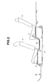
- underfoot floor panels 8L, 8R are additionally provided on a lower side of underfoot floor panels 8L, 8R, these members downwardly project from underfoot floor panels 8L, 8R by heights of these members so that there occurs the problem that electric vehicle battery pack 15 disposed beneath underfoot floor panels 8L, 8R as shown in FIG. 2 must be downsized to thereby sacrifice the battery capacity.
- FIG. 2 illustration of an internal battery unit is emitted.
- underfoot floor panels 8L, 8R can be reinforced as desired without adding the fore-and-aft member and the lateral member thereto. Therefore, the above-described problem is not caused.
- keyhole-shaped embossed portion 13 is configured to project from the lower side of underfoot floor panels 8L, 8R in the thickness direction of underfoot floor panels 8L, 8R (i.e., from the side of a road surface) toward the upper side thereof in the thickness direction (i.e., toward an inside of a vehicle compartment). Accordingly, there is no projecting portion projecting toward the lower side in the thickness direction of underfoot floor panels 8L, 8R (i.e., toward the side of a road surface). It is possible to ensure a battery installation space underneath underfoot floor panels 8L, 8R at the maximum, and therefore, cause no sacrifice of the capacity of battery pack 15.
- the number of keyhole-shaped embossed portions 13 is set to a number (three in this embodiment) necessary to ensure a required strength of underfoot floor panels 8L, 8R and reduce a panel resonance frequency thereof to a frequency (about 100 Hz) required in the electric vehicle. With this construction, it is possible to ensure the strength of underfoot floor panels 8L, 8R, and at the same time, realize the panel resonance frequency as required in the electric vehicle.
- the vehicle body panel reinforcing structure of the present invention can be applied to not only the electric vehicle but also a hybrid vehicle and a normal vehicle equipped with an internal combustion engine other than these electrically operated vehicles. Further, the vehicle body panel reinforcing structure of the present invention can be applied to not only the vehicle body floor panels such as rear seat underfoot floor panels 8L, 8R but also all vehicle body panels required to be reinforced.
- the number of elliptic embossed portions 12 extending radially outwardly from the outer circumference of circular embossed portion 11 is not particularly limited to one as shown in FIGS. 1-5 , and a plurality of elliptic embossed portions 12 may be provided.
- these elliptic embossed portions 12a, 12b are preferably arranged so as not to be diametrically opposed to each other with respect to the center of circular embossed portion 11.
- elliptic embossed portions 12a, 12b may be formed so as to have lengths different from each other.
- the elongated embossed portion is formed as elliptic embossed portions 12, 12a, 12b in the above embodiments
- the shape of the elongated embossed portion is not limited to the elliptic shape, and can be formed into an optional elongated shape such as the isosceles triangular shape as shown in FIG. 7 .
Landscapes
- Engineering & Computer Science (AREA)
- Transportation (AREA)
- Mechanical Engineering (AREA)
- Chemical & Material Sciences (AREA)
- Combustion & Propulsion (AREA)
- Aviation & Aerospace Engineering (AREA)
- Body Structure For Vehicles (AREA)
- Arrangement Or Mounting Of Propulsion Units For Vehicles (AREA)
Abstract
Description
- The present invention relates to a structure for reinforcing a vehicle body panel that constructs a vehicle body.
- In a case where a relatively large load is applied to a vehicle body panel that constructs a vehicle body, it is inevitably necessary to reinforce the vehicle body panel. Upon reinforcing the vehicle body panel in such a case, such a conventional technique as described in
Patent Literature 1 has been used in general. -
Patent Literature 1 discloses a structure for reinforcing a vehicle body panel, specifically, for reinforcing an underfoot floor panel on which feet of a passenger seated in a rear seat rest and to which a relatively large load is exerted. In the structure as described inPatent Literature 1, the floor panel is provided with a forward-and-rearward bead that extends over a substantially entire length in a forward-and-rearward direction of the vehicle such that the floor panel has a wave form in cross-section to thereby contemplate the reinforcement. - However, in the typical structure for reinforcing a vehicle body panel as described in
Patent Literature 1, it is difficult to ensure a sufficient bending strength in a direction of the wave form of the vehicle body panel, and the vehicle body panel tends to be readily deformed upon receiving a bending load in the direction of the wave form. That is, there exists such a directional dependency of degree of reinforcement of the vehicle body panel that a reaction force to a load in a specific direction is large, but a reaction force to a load in another direction is small. - For the above reason, when a thickness of the vehicle body panel is determined, it is necessary to increase a thickness of the panel in order to obtain a predetermined strength of the panel even against a bending load in a direction in which a degree of reinforcement is low. As a result, there occur problems such as an increase in weight and an increase in cost.
- In addition, in the general technique of providing the bead extending over the substantially entire length of the vehicle body panel, it is necessary to prepare a panel having a size which is increased by a shrinkage tolerance of the bead in a direction of arrangement of the bead and adjust the size of the panel upon forming the bead so as to comply with the vehicle body panel having a predetermined size. Since the panel having a size larger than that of the vehicle body panel, there will inevitably occur problems such as increase in weight and increase in cost.
- Further, in order to reinforce a vehicle body panel, it is also considered that an surface area of the vehicle body panel per se is reduced by adding a fore-and-aft member extending in a forward-and-rearward direction of the vehicle body and a lateral member extending in a width direction of the vehicle body.
However, such addition of the fore-and-aft member and the lateral member causes not only the problems such as increase in weight and increase in cost but also the following problems due to projection of these members toward one side of the vehicle body panel in a thickness direction of the vehicle body panel. - In a case where the vehicle body floor is an underfoot floor panel on which feet of a passenger seated in a rear seat rest and which is required to bear a relatively large load, the problems are explained in detail as follows.
- In a case where the fore-and-aft member and the lateral member are additionally provided on an upper side of the underfoot floor panel, an underfoot level (a heel point) at which the passenger's feet rest is raised by heights of these members so that the passenger has a strained feeling upon seating in and leaving the rear seat, or such an uncomfortable feeling that the feet are positioned at an excessively high level when the passenger is in the seated state.
- In contrast, in a case where the fore-and-aft member and the lateral member are added to a lower side of the underfoot floor panel, these members are downwardly projected by heights of these members from the underfoot floor panel. Accordingly, in a case where a large-sized battery pack is installed beneath the underfoot floor panel in an electric vehicle such as an electric vehicle and a hybrid vehicle, the battery must be downsized by an amount of projection of the members so that a capacity of the battery is sacrificed.
- Patent Literature 1: Japanese Patent Application Unexamined Publication No.
2006-232237 - An object of the present invention is to provide a structure for reinforcing a vehicle body panel which can realize reinforcement of the vehicle body panel without causing various conventional problems as described above by providing an embossed portion having a specific shape on the vehicle body panel instead of the conventional bead extending over a substantially entire length of the vehicle body panel.
- In order to achieve the above object, a structure for reinforcing a vehicle body panel that constructs a vehicle body, according to the present invention, includes a keyhole-shaped embossed portion formed by combination of a circular embossed portion and an elongated embossed portion extending in a radially outward direction of the circular embossed portion, the keyhole-shaped embossed portion being formed to project from one side of the vehicle body panel in a thickness direction of the vehicle body panel toward the other side thereof in the thickness direction.
- The structure for reinforcing a vehicle body panel according to the present invention has the following advantages. The circular embossed portion constituting a part of the keyhole-shaped embossed portion can uniformly reinforce the vehicle body panel in every direction extending through a center of the circular embossed portion. Therefore, the vehicle body panel can ensure a predetermined strength with respect to a bending load applying to the vehicle body panel in every direction. There is no directional dependency of degree of reinforcement of the vehicle body panel.
- Accordingly, upon determining a thickness of the vehicle body panel, it is not necessary to increase a thickness of the vehicle body panel on the basis of its direction in which a degree of reinforcement of the vehicle body panel is lowered. As a result, it is possible to avoid the above-described problems such as increase in weight and increase in cost which are caused due to an increased thickness of the vehicle body panel.
- On the other hand, the circular embossed portion has a drawback that it tends to undergo deformation (i.e., so-called buckling) that causes displacement of a circular bottom surface of the circular embossed portion in the thickness direction. However, in the structure according to the present invention, an embossed portion serving to reinforce the vehicle body panel is not constituted of the circular embossed portion only, but is formed as a keyhole-shaped embossed portion formed by combination of the circular embossed portion and an elongated embossed portion extending from an outer periphery of the circular embossed portion in a radially outward direction of the circular embossed portion. With this construction, the keyhole-shaped embossed portion can suppress the above-described buckling of the circular embossed portion.
- Further, the keyhole-shaped embossed portion formed by combination of the circular embossed portion and the elongated embossed portion is independently disposed between sides of the vehicle body panel which are opposed to each other, without extending over the entire length of the vehicle body panel. With this construction, the above-described function can be attained. Therefore, the panel can be prevented from shrinkage upon forming the keyhole-shaped embossed portion, thereby maintaining an outer size thereof without any change. Accordingly, merely by preparing a panel having the same size as that of each of
underfoot floor panels - Further, it is possible to attain a predetermined reinforcement of the vehicle body panel without adding the fore-and-aft member and the lateral member as described above. Accordingly, it is possible to avoid the problems such as increase in weight and increase in cost which are caused due to addition of these members. Furthermore, it is possible to avoid such problems that an underfoot level (i.e., a heel point) at which the rear seat passenger's feet rest is raised, and a capacity of a battery pack disposed beneath the vehicle body panel (i.e., an underfoot panel for the rear seat passenger's feet) is sacrificed, which are caused due to projection of these members toward one side of the vehicle body panel in a thickness direction of the vehicle body panel (i.e., an underfoot panel for the rear seat passenger's feet).
-
-
FIG. 1 is a perspective view of a vehicle body floor of an electric vehicle equipped with a vehicle body panel reinforcing structure according to a first embodiment of the present invention, when viewed from a left-upper side of the vehicle. -
FIG. 2 is a vertical cross-section of the vehicle floor, taken along line II-II as shown inFIG. 1 and viewed in a direction of an arrow, in which a front seat and a rear seat and a battery pack for the electric vehicle are shown together with the vehicle floor. -
FIG. 3 is an enlarged plan view of a rear seat underfoot floor panel of the vehicle body floor to which the vehicle body panel reinforcing structure according to the first embodiment of the present invention as shown inFIG. 1 is applied. -
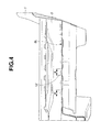
FIG. 4 is a detailed cross-section of the rear seat underfoot floor panel as shown inFIG. 3 , taken along line IV-IV ofFIG. 3 and viewed in a direction of an arrow. -
FIG. 5 is a detailed cross-section of the rear seat underfoot floor panel as shown inFIG. 3 , taken along line V-V ofFIG. 3 and viewed in a direction of an arrow. -
FIG. 6A-6C show keyhole-shaped embossed portions of the vehicle body panel reinforcing structure according to other embodiments of the present invention, respectively.FIG. 6A is a plan view of the keyhole-shaped embossed portion, in which the keyhole-shaped embossed portion includes two elliptic embossed portions that have a same length and are arranged parallel to each other.FIG. 6B is a plan view of the keyhole-shaped embossed portion, in which the keyhole-shaped embossed portion includes two elliptic embossed portions that have lengths different from each other and are arranged parallel to each other.FIG. 6C is a plan view of the keyhole-shaped embossed portion, in which the keyhole-shaped embossed portion includes two elliptic embossed portions that have a same length and are arranged perpendicular to each other. -
FIG. 7 is a plan view of a keyhole-shaped embossed portion, in which the keyhole-shaped embossed portion includes an elongated embossed portion having an isosceles triangular shape different from the elliptic embossed portions as shown inFIGS. 1-6C . - In the following, preferred embodiments of the present invention are explained in detail by referring to the accompanying drawings.
FIG. 1 is a perspective view of a vehicle body floor of an electric vehicle equipped with a vehicle body panel reinforcing structure according to a first embodiment of the present invention, when viewed from a left-upper side of the vehicle.Reference numeral 1 denotes a floor tunnel, andreference signs Reference signs floor tunnel 1 and each of left andright side sills -
Cross members right floor panels FIG. 2 ,front seat 9 is mounted ontocross members FIG. 2 ,rear seat 10 is mounted ontocross members - Left and
right floor panels underfoot floor panels rear seat 10 rest, undergo a relatively large load. For this reason, it is necessary to reinforce left and right rear-seatunderfoot floor panels floor panels - Left and right
underfoot floor panels underfoot floor panel 8L will be explained hereinafter by referring toFIGS. 3-5 .Underfoot floor panel 8L is formed with embossedportion 13 that is formed by combination of circular embossedportion 11 and elongated embossedportion 12 having an elliptic shape. Elliptic embossedportion 12 has a width A that is smaller than a diameter B of circular embossedportion 11. Elliptic embossedportion 12 is connected to an outer circumference of circular embossedportion 11 and radially outwardly extends from the outer circumference of circular embossedportion 11.Embossed portion 13 thus formed by the combination of these embossedportions - Keyhole-shaped
embossed portion 13 is arranged such that elliptic embossedportion 12 extends substantially parallel to a short side ofunderfoot floor panel 8L (i.e., a side extending in a forward-and-rearward direction of the vehicle). Keyhole-shapedembossed portion 13 is configured to project from a lower side ofunderfoot floor panel 8L in a thickness direction ofunderfoot floor panel 8L (i.e., from the side of a road surface) toward an upper side thereof in the thickness direction (i.e., toward an inside of a vehicle compartment). Further, keyhole-shapedembossed portion 13 has an entire length as measured in an extension direction of elliptic embossed portion 12 (i.e., in the forward-and-rearward direction of the vehicle) which is shorter than that ofunderfoot floor panel 8L in the same direction as the extension direction of elliptic embossedportion 12. Keyhole-shapedembossed portions 13 are disposed individually and independently of each other without extending over the entire length ofunderfoot floor panel 8L in the same direction as the extension direction of elliptic embossedportion 12. - The number of keyhole-shaped
embossed portions 13 is set to a number (three in this embodiment) necessary to ensure a required strength ofunderfoot floor panel 8L and reduce a panel resonance frequency thereof to a frequency (about 100 Hz) required in the electric vehicle. Further, in a case where the panel resonance frequency ofunderfoot floor panel 8L cannot be adjusted by the number of keyhole-shapedembossed portions 13, upwardly projecting ellipticembossed portions 14 are additionally provided onunderfoot floor panel 8L to thereby reduce the panel resonance frequency to the frequency required in the electric vehicle. - In this embodiment, keyhole-shaped
embossed portion 13 formed by the combination of circular embossedportion 11 and elliptic embossedportion 12 that has the width A smaller than the diameter B of circular embossedportion 11, is formed to project from the lower side of underfoot floor panels (vehicle body panels) 8L, 8R in the thickness direction ofunderfoot floor panels - Circular embossed
portion 11 can serve to uniformly reinforce underfoot floor panels (vehicle body panels) 8L, 8R in every direction extending through a center of circular embossedportion 11. Therefore, underfootfloor panels underfoot floor panels underfoot floor panels - Accordingly, upon determining a thickness of
underfoot floor panels - On the other hand, circular embossed
portion 11 has a drawback of easily generating deformation (i.e., so-called buckling) that causes displacement of a circular bottom surface of circular embossedportion 11 in the thickness direction ofunderfoot floor panels portion 13 is constituted of not only circular embossedportion 11 but also elliptic embossedportion 12 radially outwardly extending from the outer circumference of circular embossedportion 11, such that embossedportion 13 is formed as a keyhole-shaped embossed portion in combination of circular embossedportion 11 and elliptic embossedportion 12. With this construction, elliptic embossedportion 12 serves to suppress generation of the above-described buckling in circular embossedportion 11. - Further, keyhole-shaped
embossed portion 13 is arranged such that elliptic embossedportion 12 extends substantially parallel to the short side of each ofunderfoot floor panels portion 12 can perform a function of resisting a bending load in the fore-and-aft direction ofunderfoot floor panels portion 11. As a result, the strength ofunderfoot floor panels - Further, the entire length of keyhole-shaped
embossed portion 13 as measured in the extension direction of elliptic embossed portion 12 (i.e., in the forward-and-rearward direction of the vehicle) is shorter than that ofunderfoot floor panels portion 12. Without extending beyond the entire length ofunderfoot floor panels portion 12, keyhole-shapedembossed portions 13 are provided individually and independently of each other between the opposed sides of each ofunderfoot floor panels embossed portions 13 are formed in a panel individually and independently of each other, the panel can be prevented from suffering from shrinkage in every direction so that an outer size of the panel can be maintained without any change. Therefore, it is possible to avoid problems such as increase in weight and increase in cost due to an increased size of the panel merely by preparing a panel having the same size as that of each ofunderfoot floor panels - Besides, as apparently understood from the above discussion,
underfoot floor panels underfoot floor panels underfoot floor panels - In a case where the fore-and-aft member and the lateral member are additionally provided on an upper side of
underfoot floor panels underfoot floor panels - Conversely, in a case where the fore-and-aft member and the lateral member are additionally provided on a lower side of
underfoot floor panels underfoot floor panels vehicle battery pack 15 disposed beneathunderfoot floor panels FIG. 2 must be downsized to thereby sacrifice the battery capacity. Meanwhile, inFIG. 2 , illustration of an internal battery unit is emitted. However, in this embodiment,underfoot floor panels - Furthermore, in this embodiment, keyhole-shaped
embossed portion 13 is configured to project from the lower side ofunderfoot floor panels underfoot floor panels underfoot floor panels underfoot floor panels battery pack 15. - In addition, the number of keyhole-shaped
embossed portions 13 is set to a number (three in this embodiment) necessary to ensure a required strength ofunderfoot floor panels underfoot floor panels - In the embodiment as described above, the structure for reinforcing rear seat underfoot
floor panels floor panels - Further, the number of elliptic embossed
portions 12 extending radially outwardly from the outer circumference of circular embossedportion 11 is not particularly limited to one as shown inFIGS. 1-5 , and a plurality of elliptic embossedportions 12 may be provided. However, in such a case, for example, in a case where two ellipticembossed portions FIGS. 6A, 6B, and 6C , these ellipticembossed portions portion 11. Furthermore, as shown inFIG. 6B , ellipticembossed portions - In addition, although the elongated embossed portion is formed as elliptic
embossed portions FIG. 7 .
Claims (7)
- A structure for reinforcing a vehicle body panel that constructs a vehicle body, comprising:a keyhole-shaped embossed portion formed by combination of a circular embossed portion and an elongated embossed portion extending from an outer circumference of the circular embossed portion in a radially outward direction of the circular embossed portion,the keyhole-shaped embossed portion being formed to project from one side of the vehicle body panel in a thickness direction of the vehicle body panel toward the other side thereof in the thickness direction thereof.
- The structure for reinforcing a vehicle body panel as claimed in claim 1, wherein the keyhole-shaped embossed portion is formed such that the elongated embossed portion has a width smaller than a diameter of the circular embossed portion.
- The structure for reinforcing a vehicle body panel as claimed in claim 1 or 2, wherein the keyhole-shaped embossed portion is arranged such that the elongated embossed portion extends substantially parallel to a short side of the vehicle body panel.
- The structure for reinforcing a vehicle body panel as claimed in any one of claims 1-3, wherein the keyhole-shaped embossed portion has an entire length as measured in an extension direction of the elongated embossed portion which is shorter than that of the vehicle body panel in a same direction as the extension direction of the elongated embossed portion.
- The structure for reinforcing a vehicle body panel as claimed in any one of claims 1-4, wherein the vehicle body panel is a vehicle body floor panel that constructs an underfoot floor on which feet of a passenger seated in a rear seat rest, and the keyhole-shaped embossed portion is configured to project from a lower side of the vehicle body floor panel in a thickness direction of the vehicle body floor panel toward an upper side thereof in the thickness direction thereof.
- The structure for reinforcing a vehicle body panel as claimed in claim 5, wherein a battery installation space in which a battery is installed is provided underneath the vehicle body floor panel.
- The structure for reinforcing a vehicle body panel as claimed in claim 5 or 6, wherein the vehicle body is a vehicle body of an electric vehicle, and the vehicle body of an electric vehicle has a number of the keyhole-shaped embossed portion which is necessary to ensure a required strength of the vehicle body floor panel and reduce a panel resonance frequency to a frequency required in the electric vehicle.
Applications Claiming Priority (2)
| Application Number | Priority Date | Filing Date | Title |
|---|---|---|---|
| JP2010129532A JP5604996B2 (en) | 2010-06-07 | 2010-06-07 | Body panel reinforcement structure |
| PCT/JP2011/057836 WO2011155249A1 (en) | 2010-06-07 | 2011-03-29 | Structure for reinforcing panel of car body |
Publications (3)
| Publication Number | Publication Date |
|---|---|
| EP2578477A1 true EP2578477A1 (en) | 2013-04-10 |
| EP2578477A4 EP2578477A4 (en) | 2015-11-11 |
| EP2578477B1 EP2578477B1 (en) | 2019-05-22 |
Family
ID=45097864
Family Applications (1)
| Application Number | Title | Priority Date | Filing Date |
|---|---|---|---|
| EP11792207.0A Active EP2578477B1 (en) | 2010-06-07 | 2011-03-29 | Structure for reinforcing panel of car body |
Country Status (9)
| Country | Link |
|---|---|
| US (1) | US9033405B2 (en) |
| EP (1) | EP2578477B1 (en) |
| JP (1) | JP5604996B2 (en) |
| CN (1) | CN102933451B (en) |
| BR (1) | BR112012030943B1 (en) |
| MX (1) | MX2012013558A (en) |
| MY (1) | MY155750A (en) |
| RU (1) | RU2526580C1 (en) |
| WO (1) | WO2011155249A1 (en) |
Cited By (1)
| Publication number | Priority date | Publication date | Assignee | Title |
|---|---|---|---|---|
| FR3153798A1 (en) * | 2023-10-09 | 2025-04-11 | Psa Automobiles Sa | VEHICLE FLOOR, SUITABLE FOR SUPPORTING A STRUT OF A CHILD SEAT |
Families Citing this family (5)
| Publication number | Priority date | Publication date | Assignee | Title |
|---|---|---|---|---|
| US10343554B2 (en) * | 2016-09-07 | 2019-07-09 | Thunder Power New Energy Vehicle Development Company Limited | Seat rail |
| JP6631472B2 (en) * | 2016-11-07 | 2020-01-15 | トヨタ自動車株式会社 | Vehicle undercarriage |
| JP6915592B2 (en) * | 2018-06-15 | 2021-08-04 | マツダ株式会社 | Lower body structure |
| US10994795B1 (en) * | 2021-01-25 | 2021-05-04 | Vantage Mobility International, Llc | Mobility-assist hybrid conversion vehicles and methods of manufacturing the same |
| JP7765928B2 (en) * | 2021-09-23 | 2025-11-07 | 株式会社Subaru | Vehicle having a directional patterned embossed surface on the underside of the vehicle body, and vehicle undercover member |
Family Cites Families (23)
| Publication number | Priority date | Publication date | Assignee | Title |
|---|---|---|---|---|
| US1624903A (en) * | 1923-12-05 | 1927-04-12 | American Motor Body Corp | Vehicle underbody construction |
| FR2053884A5 (en) * | 1969-07-22 | 1971-04-16 | Peugeot & Renault | |
| JPS56120460A (en) * | 1980-02-27 | 1981-09-21 | Mazda Motor Corp | Body panel structure of automobile |
| JP3084734B2 (en) * | 1990-09-25 | 2000-09-04 | 日産自動車株式会社 | Panel structure batteries for electric vehicles |
| US5704644A (en) * | 1993-02-27 | 1998-01-06 | Esoro Ag | Lightweight road vehicle with strengthening structure |
| JP3399732B2 (en) * | 1996-01-29 | 2003-04-21 | マツダ株式会社 | Method of reducing radiation noise of vehicle body panel and vehicle body panel |
| JP3536813B2 (en) * | 2000-11-29 | 2004-06-14 | トヨタ車体株式会社 | Vehicle floor panel structure |
| JP2002302071A (en) * | 2001-04-06 | 2002-10-15 | Honda Motor Co Ltd | Vehicle floor panel |
| US6793276B2 (en) * | 2001-07-30 | 2004-09-21 | Mazda Motor Corporation | Automobile floor structure |
| JP3831264B2 (en) | 2002-01-21 | 2006-10-11 | 株式会社日立製作所 | Electric vehicle control device |
| JP3719235B2 (en) | 2002-07-08 | 2005-11-24 | 日産自動車株式会社 | Thin battery, assembled battery, composite assembled battery and vehicle |
| JP4175107B2 (en) * | 2002-12-27 | 2008-11-05 | 三菱自動車工業株式会社 | Vehicle floor panel |
| EP1439110A3 (en) * | 2003-01-16 | 2004-11-03 | Mazda Motor Corporation | Floor panel structure of vehicle body |
| JP4168812B2 (en) * | 2003-04-07 | 2008-10-22 | 三菱自動車工業株式会社 | Connecting structure at the rear of the car body |
| JP4022919B2 (en) * | 2003-04-25 | 2007-12-19 | マツダ株式会社 | Body floor panel structure |
| JP4019421B2 (en) | 2003-08-20 | 2007-12-12 | マツダ株式会社 | Automotive floor panel structure |
| JP2005335578A (en) * | 2004-05-27 | 2005-12-08 | Mazda Motor Corp | Car body floor panel structure |
| FR2878222B1 (en) | 2004-11-19 | 2007-01-26 | Renault Sas | AUTOMOTIVE VEHICLE COMPRISING A STRUCTURE WITH A LOADING FLOOR |
| JP4655667B2 (en) * | 2005-02-23 | 2011-03-23 | 日産自動車株式会社 | Electric motor control device for vehicle |
| JP4469296B2 (en) | 2005-02-28 | 2010-05-26 | 本田技研工業株式会社 | Automotive floor panels |
| RU51583U1 (en) | 2005-05-11 | 2006-02-27 | Открытое акционерное общество "АВТОВАЗ" | REAR PART OF A BODY OF A PASSENGER CAR |
| JP4858183B2 (en) * | 2007-01-22 | 2012-01-18 | 日産自動車株式会社 | Lower body structure |
| JP4690450B2 (en) * | 2008-12-19 | 2011-06-01 | 本田技研工業株式会社 | Body floor structure |
-
2010
- 2010-06-07 JP JP2010129532A patent/JP5604996B2/en active Active
-
2011
- 2011-03-29 RU RU2012157094/11A patent/RU2526580C1/en active
- 2011-03-29 BR BR112012030943-9A patent/BR112012030943B1/en active IP Right Grant
- 2011-03-29 WO PCT/JP2011/057836 patent/WO2011155249A1/en not_active Ceased
- 2011-03-29 MX MX2012013558A patent/MX2012013558A/en active IP Right Grant
- 2011-03-29 MY MYPI2012005280A patent/MY155750A/en unknown
- 2011-03-29 EP EP11792207.0A patent/EP2578477B1/en active Active
- 2011-03-29 US US13/702,158 patent/US9033405B2/en active Active
- 2011-03-29 CN CN201180028374.9A patent/CN102933451B/en active Active
Cited By (1)
| Publication number | Priority date | Publication date | Assignee | Title |
|---|---|---|---|---|
| FR3153798A1 (en) * | 2023-10-09 | 2025-04-11 | Psa Automobiles Sa | VEHICLE FLOOR, SUITABLE FOR SUPPORTING A STRUT OF A CHILD SEAT |
Also Published As
| Publication number | Publication date |
|---|---|
| CN102933451B (en) | 2015-09-02 |
| MX2012013558A (en) | 2013-01-24 |
| EP2578477B1 (en) | 2019-05-22 |
| US9033405B2 (en) | 2015-05-19 |
| JP5604996B2 (en) | 2014-10-15 |
| RU2526580C1 (en) | 2014-08-27 |
| BR112012030943A2 (en) | 2016-11-01 |
| CN102933451A (en) | 2013-02-13 |
| JP2011255709A (en) | 2011-12-22 |
| US20130076077A1 (en) | 2013-03-28 |
| BR112012030943B1 (en) | 2020-10-27 |
| MY155750A (en) | 2015-11-30 |
| EP2578477A4 (en) | 2015-11-11 |
| RU2012157094A (en) | 2014-07-20 |
| WO2011155249A1 (en) | 2011-12-15 |
Similar Documents
| Publication | Publication Date | Title |
|---|---|---|
| CN111469935B (en) | The rear body structure of the vehicle | |
| EP2578477B1 (en) | Structure for reinforcing panel of car body | |
| CN102245417B (en) | Hybrid vehicle structure | |
| CN102205857B (en) | Vehicle body structure | |
| US10118482B2 (en) | Vehicle body structure | |
| EP3118088B1 (en) | Assembling structure of vehicle body | |
| JP2016150687A (en) | Vehicle body structure | |
| CN106809286B (en) | car front floor structure | |
| US20170015364A1 (en) | Floor body for vehicle | |
| CN109204540B (en) | Vehicle body structure and vehicle | |
| JP2026512424A (en) | Vehicle body structure and vehicle | |
| US11377157B2 (en) | Vehicle rear structure | |
| JP4269937B2 (en) | Vehicle fuel tank arrangement structure | |
| JP6693093B2 (en) | vehicle | |
| JP7711836B2 (en) | Vehicle cargo box structure | |
| JP2021062813A (en) | Vehicle body structure | |
| JP7779049B2 (en) | Body floor structure | |
| JP2015101142A (en) | Floor structure for vehicle rear part | |
| JP5359235B2 (en) | Body front structure | |
| CN107839760A (en) | Preceding floor assembly and electric automobile | |
| JP2008001147A (en) | High-piezoelectric component installation structure | |
| JP5233382B2 (en) | Lower body structure | |
| JP2013010439A (en) | Footrest for vehicle | |
| KR20210016904A (en) | Vehicle body structure and vehicle including the same | |
| JP2009248636A (en) | Vehicular floor structure |
Legal Events
| Date | Code | Title | Description |
|---|---|---|---|
| PUAI | Public reference made under article 153(3) epc to a published international application that has entered the european phase |
Free format text: ORIGINAL CODE: 0009012 |
|
| 17P | Request for examination filed |
Effective date: 20130107 |
|
| AK | Designated contracting states |
Kind code of ref document: A1 Designated state(s): AL AT BE BG CH CY CZ DE DK EE ES FI FR GB GR HR HU IE IS IT LI LT LU LV MC MK MT NL NO PL PT RO RS SE SI SK SM TR |
|
| DAX | Request for extension of the european patent (deleted) | ||
| RA4 | Supplementary search report drawn up and despatched (corrected) |
Effective date: 20151013 |
|
| RIC1 | Information provided on ipc code assigned before grant |
Ipc: B62D 25/20 20060101AFI20151007BHEP |
|
| GRAP | Despatch of communication of intention to grant a patent |
Free format text: ORIGINAL CODE: EPIDOSNIGR1 |
|
| STAA | Information on the status of an ep patent application or granted ep patent |
Free format text: STATUS: GRANT OF PATENT IS INTENDED |
|
| INTG | Intention to grant announced |
Effective date: 20181019 |
|
| GRAJ | Information related to disapproval of communication of intention to grant by the applicant or resumption of examination proceedings by the epo deleted |
Free format text: ORIGINAL CODE: EPIDOSDIGR1 |
|
| STAA | Information on the status of an ep patent application or granted ep patent |
Free format text: STATUS: REQUEST FOR EXAMINATION WAS MADE |
|
| GRAP | Despatch of communication of intention to grant a patent |
Free format text: ORIGINAL CODE: EPIDOSNIGR1 |
|
| STAA | Information on the status of an ep patent application or granted ep patent |
Free format text: STATUS: GRANT OF PATENT IS INTENDED |
|
| INTC | Intention to grant announced (deleted) | ||
| INTG | Intention to grant announced |
Effective date: 20190306 |
|
| GRAS | Grant fee paid |
Free format text: ORIGINAL CODE: EPIDOSNIGR3 |
|
| GRAA | (expected) grant |
Free format text: ORIGINAL CODE: 0009210 |
|
| STAA | Information on the status of an ep patent application or granted ep patent |
Free format text: STATUS: THE PATENT HAS BEEN GRANTED |
|
| AK | Designated contracting states |
Kind code of ref document: B1 Designated state(s): AL AT BE BG CH CY CZ DE DK EE ES FI FR GB GR HR HU IE IS IT LI LT LU LV MC MK MT NL NO PL PT RO RS SE SI SK SM TR |
|
| REG | Reference to a national code |
Ref country code: GB Ref legal event code: FG4D |
|
| REG | Reference to a national code |
Ref country code: CH Ref legal event code: EP |
|
| REG | Reference to a national code |
Ref country code: IE Ref legal event code: FG4D |
|
| REG | Reference to a national code |
Ref country code: DE Ref legal event code: R096 Ref document number: 602011059221 Country of ref document: DE |
|
| REG | Reference to a national code |
Ref country code: AT Ref legal event code: REF Ref document number: 1135754 Country of ref document: AT Kind code of ref document: T Effective date: 20190615 |
|
| REG | Reference to a national code |
Ref country code: NL Ref legal event code: MP Effective date: 20190522 |
|
| REG | Reference to a national code |
Ref country code: LT Ref legal event code: MG4D |
|
| PG25 | Lapsed in a contracting state [announced via postgrant information from national office to epo] |
Ref country code: HR Free format text: LAPSE BECAUSE OF FAILURE TO SUBMIT A TRANSLATION OF THE DESCRIPTION OR TO PAY THE FEE WITHIN THE PRESCRIBED TIME-LIMIT Effective date: 20190522 Ref country code: NL Free format text: LAPSE BECAUSE OF FAILURE TO SUBMIT A TRANSLATION OF THE DESCRIPTION OR TO PAY THE FEE WITHIN THE PRESCRIBED TIME-LIMIT Effective date: 20190522 Ref country code: FI Free format text: LAPSE BECAUSE OF FAILURE TO SUBMIT A TRANSLATION OF THE DESCRIPTION OR TO PAY THE FEE WITHIN THE PRESCRIBED TIME-LIMIT Effective date: 20190522 Ref country code: LT Free format text: LAPSE BECAUSE OF FAILURE TO SUBMIT A TRANSLATION OF THE DESCRIPTION OR TO PAY THE FEE WITHIN THE PRESCRIBED TIME-LIMIT Effective date: 20190522 Ref country code: PT Free format text: LAPSE BECAUSE OF FAILURE TO SUBMIT A TRANSLATION OF THE DESCRIPTION OR TO PAY THE FEE WITHIN THE PRESCRIBED TIME-LIMIT Effective date: 20190922 Ref country code: SE Free format text: LAPSE BECAUSE OF FAILURE TO SUBMIT A TRANSLATION OF THE DESCRIPTION OR TO PAY THE FEE WITHIN THE PRESCRIBED TIME-LIMIT Effective date: 20190522 Ref country code: NO Free format text: LAPSE BECAUSE OF FAILURE TO SUBMIT A TRANSLATION OF THE DESCRIPTION OR TO PAY THE FEE WITHIN THE PRESCRIBED TIME-LIMIT Effective date: 20190822 Ref country code: AL Free format text: LAPSE BECAUSE OF FAILURE TO SUBMIT A TRANSLATION OF THE DESCRIPTION OR TO PAY THE FEE WITHIN THE PRESCRIBED TIME-LIMIT Effective date: 20190522 Ref country code: ES Free format text: LAPSE BECAUSE OF FAILURE TO SUBMIT A TRANSLATION OF THE DESCRIPTION OR TO PAY THE FEE WITHIN THE PRESCRIBED TIME-LIMIT Effective date: 20190522 |
|
| PG25 | Lapsed in a contracting state [announced via postgrant information from national office to epo] |
Ref country code: GR Free format text: LAPSE BECAUSE OF FAILURE TO SUBMIT A TRANSLATION OF THE DESCRIPTION OR TO PAY THE FEE WITHIN THE PRESCRIBED TIME-LIMIT Effective date: 20190823 Ref country code: BG Free format text: LAPSE BECAUSE OF FAILURE TO SUBMIT A TRANSLATION OF THE DESCRIPTION OR TO PAY THE FEE WITHIN THE PRESCRIBED TIME-LIMIT Effective date: 20190822 Ref country code: RS Free format text: LAPSE BECAUSE OF FAILURE TO SUBMIT A TRANSLATION OF THE DESCRIPTION OR TO PAY THE FEE WITHIN THE PRESCRIBED TIME-LIMIT Effective date: 20190522 Ref country code: LV Free format text: LAPSE BECAUSE OF FAILURE TO SUBMIT A TRANSLATION OF THE DESCRIPTION OR TO PAY THE FEE WITHIN THE PRESCRIBED TIME-LIMIT Effective date: 20190522 |
|
| REG | Reference to a national code |
Ref country code: AT Ref legal event code: MK05 Ref document number: 1135754 Country of ref document: AT Kind code of ref document: T Effective date: 20190522 |
|
| PG25 | Lapsed in a contracting state [announced via postgrant information from national office to epo] |
Ref country code: EE Free format text: LAPSE BECAUSE OF FAILURE TO SUBMIT A TRANSLATION OF THE DESCRIPTION OR TO PAY THE FEE WITHIN THE PRESCRIBED TIME-LIMIT Effective date: 20190522 Ref country code: AT Free format text: LAPSE BECAUSE OF FAILURE TO SUBMIT A TRANSLATION OF THE DESCRIPTION OR TO PAY THE FEE WITHIN THE PRESCRIBED TIME-LIMIT Effective date: 20190522 Ref country code: SK Free format text: LAPSE BECAUSE OF FAILURE TO SUBMIT A TRANSLATION OF THE DESCRIPTION OR TO PAY THE FEE WITHIN THE PRESCRIBED TIME-LIMIT Effective date: 20190522 Ref country code: DK Free format text: LAPSE BECAUSE OF FAILURE TO SUBMIT A TRANSLATION OF THE DESCRIPTION OR TO PAY THE FEE WITHIN THE PRESCRIBED TIME-LIMIT Effective date: 20190522 Ref country code: RO Free format text: LAPSE BECAUSE OF FAILURE TO SUBMIT A TRANSLATION OF THE DESCRIPTION OR TO PAY THE FEE WITHIN THE PRESCRIBED TIME-LIMIT Effective date: 20190522 Ref country code: CZ Free format text: LAPSE BECAUSE OF FAILURE TO SUBMIT A TRANSLATION OF THE DESCRIPTION OR TO PAY THE FEE WITHIN THE PRESCRIBED TIME-LIMIT Effective date: 20190522 |
|
| REG | Reference to a national code |
Ref country code: DE Ref legal event code: R097 Ref document number: 602011059221 Country of ref document: DE |
|
| PG25 | Lapsed in a contracting state [announced via postgrant information from national office to epo] |
Ref country code: SM Free format text: LAPSE BECAUSE OF FAILURE TO SUBMIT A TRANSLATION OF THE DESCRIPTION OR TO PAY THE FEE WITHIN THE PRESCRIBED TIME-LIMIT Effective date: 20190522 Ref country code: IT Free format text: LAPSE BECAUSE OF FAILURE TO SUBMIT A TRANSLATION OF THE DESCRIPTION OR TO PAY THE FEE WITHIN THE PRESCRIBED TIME-LIMIT Effective date: 20190522 |
|
| PLBE | No opposition filed within time limit |
Free format text: ORIGINAL CODE: 0009261 |
|
| STAA | Information on the status of an ep patent application or granted ep patent |
Free format text: STATUS: NO OPPOSITION FILED WITHIN TIME LIMIT |
|
| PG25 | Lapsed in a contracting state [announced via postgrant information from national office to epo] |
Ref country code: TR Free format text: LAPSE BECAUSE OF FAILURE TO SUBMIT A TRANSLATION OF THE DESCRIPTION OR TO PAY THE FEE WITHIN THE PRESCRIBED TIME-LIMIT Effective date: 20190522 |
|
| 26N | No opposition filed |
Effective date: 20200225 |
|
| PG25 | Lapsed in a contracting state [announced via postgrant information from national office to epo] |
Ref country code: PL Free format text: LAPSE BECAUSE OF FAILURE TO SUBMIT A TRANSLATION OF THE DESCRIPTION OR TO PAY THE FEE WITHIN THE PRESCRIBED TIME-LIMIT Effective date: 20190522 |
|
| PG25 | Lapsed in a contracting state [announced via postgrant information from national office to epo] |
Ref country code: SI Free format text: LAPSE BECAUSE OF FAILURE TO SUBMIT A TRANSLATION OF THE DESCRIPTION OR TO PAY THE FEE WITHIN THE PRESCRIBED TIME-LIMIT Effective date: 20190522 |
|
| PG25 | Lapsed in a contracting state [announced via postgrant information from national office to epo] |
Ref country code: MC Free format text: LAPSE BECAUSE OF FAILURE TO SUBMIT A TRANSLATION OF THE DESCRIPTION OR TO PAY THE FEE WITHIN THE PRESCRIBED TIME-LIMIT Effective date: 20190522 |
|
| REG | Reference to a national code |
Ref country code: CH Ref legal event code: PL |
|
| REG | Reference to a national code |
Ref country code: BE Ref legal event code: MM Effective date: 20200331 |
|
| PG25 | Lapsed in a contracting state [announced via postgrant information from national office to epo] |
Ref country code: LU Free format text: LAPSE BECAUSE OF NON-PAYMENT OF DUE FEES Effective date: 20200329 |
|
| PG25 | Lapsed in a contracting state [announced via postgrant information from national office to epo] |
Ref country code: IE Free format text: LAPSE BECAUSE OF NON-PAYMENT OF DUE FEES Effective date: 20200329 Ref country code: CH Free format text: LAPSE BECAUSE OF NON-PAYMENT OF DUE FEES Effective date: 20200331 Ref country code: LI Free format text: LAPSE BECAUSE OF NON-PAYMENT OF DUE FEES Effective date: 20200331 |
|
| PG25 | Lapsed in a contracting state [announced via postgrant information from national office to epo] |
Ref country code: BE Free format text: LAPSE BECAUSE OF NON-PAYMENT OF DUE FEES Effective date: 20200331 |
|
| PG25 | Lapsed in a contracting state [announced via postgrant information from national office to epo] |
Ref country code: MT Free format text: LAPSE BECAUSE OF FAILURE TO SUBMIT A TRANSLATION OF THE DESCRIPTION OR TO PAY THE FEE WITHIN THE PRESCRIBED TIME-LIMIT Effective date: 20190522 Ref country code: CY Free format text: LAPSE BECAUSE OF FAILURE TO SUBMIT A TRANSLATION OF THE DESCRIPTION OR TO PAY THE FEE WITHIN THE PRESCRIBED TIME-LIMIT Effective date: 20190522 |
|
| PG25 | Lapsed in a contracting state [announced via postgrant information from national office to epo] |
Ref country code: MK Free format text: LAPSE BECAUSE OF FAILURE TO SUBMIT A TRANSLATION OF THE DESCRIPTION OR TO PAY THE FEE WITHIN THE PRESCRIBED TIME-LIMIT Effective date: 20190522 Ref country code: IS Free format text: LAPSE BECAUSE OF FAILURE TO SUBMIT A TRANSLATION OF THE DESCRIPTION OR TO PAY THE FEE WITHIN THE PRESCRIBED TIME-LIMIT Effective date: 20190922 |
|
| PGFP | Annual fee paid to national office [announced via postgrant information from national office to epo] |
Ref country code: GB Payment date: 20260220 Year of fee payment: 16 |
|
| PGFP | Annual fee paid to national office [announced via postgrant information from national office to epo] |
Ref country code: DE Payment date: 20260219 Year of fee payment: 16 |
|
| PGFP | Annual fee paid to national office [announced via postgrant information from national office to epo] |
Ref country code: FR Payment date: 20260220 Year of fee payment: 16 |