EP2578420A1 - Tire comprising a tube assembly and method of assembling an elongate air tube within a tire - Google Patents
Tire comprising a tube assembly and method of assembling an elongate air tube within a tire Download PDFInfo
- Publication number
- EP2578420A1 EP2578420A1 EP20120187039 EP12187039A EP2578420A1 EP 2578420 A1 EP2578420 A1 EP 2578420A1 EP 20120187039 EP20120187039 EP 20120187039 EP 12187039 A EP12187039 A EP 12187039A EP 2578420 A1 EP2578420 A1 EP 2578420A1
- Authority
- EP
- European Patent Office
- Prior art keywords
- groove
- tire
- air tube
- sidewall
- air
- Prior art date
- Legal status (The legal status is an assumption and is not a legal conclusion. Google has not performed a legal analysis and makes no representation as to the accuracy of the status listed.)
- Granted
Links
Images







Classifications
-
- B—PERFORMING OPERATIONS; TRANSPORTING
- B60—VEHICLES IN GENERAL
- B60C—VEHICLE TYRES; TYRE INFLATION; TYRE CHANGING; CONNECTING VALVES TO INFLATABLE ELASTIC BODIES IN GENERAL; DEVICES OR ARRANGEMENTS RELATED TO TYRES
- B60C23/00—Devices for measuring, signalling, controlling, or distributing tyre pressure or temperature, specially adapted for mounting on vehicles; Arrangement of tyre inflating devices on vehicles, e.g. of pumps or of tanks; Tyre cooling arrangements
- B60C23/10—Arrangement of tyre-inflating pumps mounted on vehicles
- B60C23/12—Arrangement of tyre-inflating pumps mounted on vehicles operated by a running wheel
- B60C23/121—Arrangement of tyre-inflating pumps mounted on vehicles operated by a running wheel the pumps being mounted on the tyres
- B60C23/123—Elongate peristaltic pumps
-
- B—PERFORMING OPERATIONS; TRANSPORTING
- B60—VEHICLES IN GENERAL
- B60C—VEHICLE TYRES; TYRE INFLATION; TYRE CHANGING; CONNECTING VALVES TO INFLATABLE ELASTIC BODIES IN GENERAL; DEVICES OR ARRANGEMENTS RELATED TO TYRES
- B60C23/00—Devices for measuring, signalling, controlling, or distributing tyre pressure or temperature, specially adapted for mounting on vehicles; Arrangement of tyre inflating devices on vehicles, e.g. of pumps or of tanks; Tyre cooling arrangements
- B60C23/10—Arrangement of tyre-inflating pumps mounted on vehicles
- B60C23/12—Arrangement of tyre-inflating pumps mounted on vehicles operated by a running wheel
- B60C23/135—Arrangement of tyre-inflating pumps mounted on vehicles operated by a running wheel activated due to tyre deformation
-
- Y—GENERAL TAGGING OF NEW TECHNOLOGICAL DEVELOPMENTS; GENERAL TAGGING OF CROSS-SECTIONAL TECHNOLOGIES SPANNING OVER SEVERAL SECTIONS OF THE IPC; TECHNICAL SUBJECTS COVERED BY FORMER USPC CROSS-REFERENCE ART COLLECTIONS [XRACs] AND DIGESTS
- Y10—TECHNICAL SUBJECTS COVERED BY FORMER USPC
- Y10T—TECHNICAL SUBJECTS COVERED BY FORMER US CLASSIFICATION
- Y10T152/00—Resilient tires and wheels
- Y10T152/10—Tires, resilient
- Y10T152/10495—Pneumatic tire or inner tube
-
- Y—GENERAL TAGGING OF NEW TECHNOLOGICAL DEVELOPMENTS; GENERAL TAGGING OF CROSS-SECTIONAL TECHNOLOGIES SPANNING OVER SEVERAL SECTIONS OF THE IPC; TECHNICAL SUBJECTS COVERED BY FORMER USPC CROSS-REFERENCE ART COLLECTIONS [XRACs] AND DIGESTS
- Y10—TECHNICAL SUBJECTS COVERED BY FORMER USPC
- Y10T—TECHNICAL SUBJECTS COVERED BY FORMER US CLASSIFICATION
- Y10T29/00—Metal working
- Y10T29/49—Method of mechanical manufacture
- Y10T29/49481—Wheel making
- Y10T29/49492—Land wheel
- Y10T29/49538—Tyre making
-
- Y—GENERAL TAGGING OF NEW TECHNOLOGICAL DEVELOPMENTS; GENERAL TAGGING OF CROSS-SECTIONAL TECHNOLOGIES SPANNING OVER SEVERAL SECTIONS OF THE IPC; TECHNICAL SUBJECTS COVERED BY FORMER USPC CROSS-REFERENCE ART COLLECTIONS [XRACs] AND DIGESTS
- Y10—TECHNICAL SUBJECTS COVERED BY FORMER USPC
- Y10T—TECHNICAL SUBJECTS COVERED BY FORMER US CLASSIFICATION
- Y10T29/00—Metal working
- Y10T29/49—Method of mechanical manufacture
- Y10T29/49826—Assembling or joining
Definitions
- the invention relates generally to tire comprising an air tube in a sidewall groove and to a method of assembling such an air tube within the tire, and, more specifically, to an air maintenance tire and a pumping tube assembly therefore and method of assembly.
- Tire Pressure Monitoring Systems have been proposed to warn drivers when tire pressure is significantly low. Such systems, however, remain dependant upon the driver taking remedial action when warned to re-inflate a tire to recommended pressure. It is a desirable, therefore, to incorporate an air maintenance feature within a tire that will re-inflate the tire in order to compensate for any reduction in tire pressure over time without the need for driver intervention.
- the invention relates to a tire in accordance with claim 1 and to a method in accordance with claim 11.
- a tire having an elongate sidewall groove extending into a first tire sidewall from an outward first sidewall surface; the sidewall groove having an outer groove entry opening, a groove entry chamber axially inward from the groove entry opening defined by divergent entry chamber sidewalls, and a groove primary chamber axially inward from the groove entry chamber.
- the groove entry chamber sidewalls and the groove primary chamber sidewalls intersect to form at the intersection a detent channel.
- An elongate air tube is positioned within the elongate sidewall groove in contact with the groove primary chamber sidewalls.
- the air tube has an external surface configuration corresponding with the sidewall configuration defining the elongate sidewall groove.
- the air tube body has an external protrusion configured and dimensioned to register and seat within the detent channel of the sidewall groove.
- the air tube in yet another preferred aspect of the invention, is formed of resilient material operative when subject to outward originating impinging force on the air tube to collapse from an expanded unstressed configuration into a collapsed configuration to allow the tube to insert through the groove entry opening and expand outwardly once within the sidewall groove to its unstressed configuration.
- a method for inserting a so-configured air tube into a sidewall groove of a tire including collapsing the air tube from an expanded unstressed configuration into a collapsed configuration to allow the tube to insert through the groove entry opening and expanding the tube outwardly once within the sidewall groove to its unstressed configuration.
- Axial and “axially” means lines or directions that are parallel to the axis of rotation of the tire.
- “Footprint” means the contact patch or area of contact of the tire tread with a flat surface at zero speed and under normal load and pressure.
- “Groove” means an elongated void area in a tire wall that may extend circumferentially or laterally about the tire wall.
- the "groove width” is equal to its average width over its length.
- a grooves is sized to accommodate an air tube as described.
- Periodaltic means operating by means of wave-like contractions that propel contained matter, such as air, along tubular pathways.
- Ring and radially means directions radially toward or away from the axis of rotation of the tire.
- a tire assembly 10 includes a tire 12, a peristaltic pump assembly 14, and a tire rim 16.
- the tire mounts in conventional fashion to a pair of rim mounting surfaces 18, 20 adjacent outer rim flanges 22, 24.
- a rim body 28 supports the tire assembly as shown.
- the tire is of conventional construction, having a pair of sidewalls 30, 32 extending from opposite bead areas 34, 36 to a crown or tire tread region 38.
- the tire and rim enclose a tire cavity 40.
- the peristaltic pump assembly 14 includes an annular air tube 42 that encloses an annular passageway 43.
- the tube 42 is formed of a resilient, flexible material such as plastic or rubber compounds that are capable of withstanding repeated deformation cycles wherein the tube is deformed into a flattened condition subject to external force and, upon removal of such force, returns to an original condition.
- the tube passageway 43 is generally elliptical in section and is of a diameter sufficient to operatively pass a volume of air sufficient for the purposes described herein and allowing a positioning of the tube in an operable location within the tire assembly as will be described.
- the tube 42 is elongate and circular.
- the tube 42 is asymmetric about an elongate major axis and is constructed having an outward flat end surface 44, a tapered protruding outward portion 46, and a main body portion 48.
- the protruding portion 46 of the tube 42 is defined by beveled surfaces 52, 54 that diverge from the flat tube surface 44 to an arcuate outward surface 56 of the main body portion 48 of the tube 42.
- a pair of shoulders 57, 59, respectively, are formed which extend the length of tube 42 on opposite respective sides of protruding portion 46.
- An elongate groove 58 is formed to extend into an axially outward surface of a sidewall such as sidewall 30, preferably in the geometric form of an annular ring.
- the other sidewall may be grooved or both sidewalls if so desired.
- the groove 58 has an internal sectional profile complementary with the external geometry of the tube 42, and includes an entry opening 60 exposed to the outer surface 61 of the sidewall 30.
- the groove 58 is formed to provide an entry chamber 62 adjacent to and axially inward of the opening 60 and a primary chamber 64 axially inward from and adjacent to the entry chamber 62.
- the entry chamber 62 is defined by beveled sidewalls 66, 68 diverging axially inward from the opening 60 and the primary chamber is defined by primary chamber sidewalls 70.
- a pair of shoulders detent channels 72, 74, respectively, are formed which extend the length of groove 58 on opposite respective sides of the groove.
- the tube 42 has a transverse sectional width length L1 within a preferred range of 3.65 to 3.8 mm; a preferred height of D1 within a range of 2.2 to 3.8 mm; a trailing end preferred width of D3 within a range of 0.8 to 1 mm.
- the internal air passageway 43 is generally elliptical having a length L2 along a major axis within a preferred range of 2.2 to 2.3 mm, and a width D2 along a transverse axis within a preferred range of 0.5 to 0.9 mm.
- the tube 42 has an axial distance L3 between the end surface 44 and the center of the passageway 43 lying within a preferred range of 1.8 to 2 mm.
- the groove 58 is of complementary internal geometry to accommodate close receipt of the tube 42. As shown in FIG. 8A , the groove 58 is dimensionally compatible for receipt of the tube 42, and incorporates dimensions D1, D3, L1, L3 within the preferred ranges previously set forth with respect to the tube 42.
- the primary chamber 64 is radiussed by a radius R1 lying within a preferred range of 1.1 to 1.9 mm.
- the beveled surfaces 66, 68 and complementary divergent surfaces 52, 54 of the tube 42 are sloped at generally an acute angle of approximately 45 degrees.
- insertion of the tube 42 into the groove 58 is initiated by axially aligning the tube 42 with the entry opening 60 of the groove 58; compressing the tube 42 in the direction of arrows 76 so as to reduce the groove height, whereby collapsing the groove air passageway 43; inserting the tube 42 laterally through the groove opening 60 and into the space defined by entry chamber 62 and primary chamber 64; removing the compression force at arrows 76, thereby freeing the tube 42 to expand outward into its nominal unstressed configuration of FIGS. 8A , 8C , and 8D and occupy the groove 58.
- the tube 42 is thus located within the groove 58 with external surfaces of the groove disposed adjacent to corresponding complementary sidewalls defining the groove 58.
- the shoulders 57, 59 of the tube 42 register within the detent channels 72, 74 formed at the intersection of groove sidewalls 66, 68 and 70. So registered, the divergent sides 52, 54 of the tube abut the entry chamber divergent sidewalls 66, 68, respectively, and thereby retain the tube 42 within the groove 58.
- the peristaltic pump assembly 14 further includes an inlet device 78 and an outlet device 80 preferably spaced apart approximately 180 degrees at respective locations along the circumferential air tube 42.
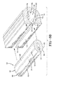
- the outlet device 80 as shown in FIGS. 3A through 3C , has a T-shaped configuration in which conduits 82, 84 direct air to and from the tire cavity 40.
- An outlet device housing 86 contains conduit arm extensions 88, 90 that integrally extend at right angles from respective conduits 82, 84.
- Each of the conduit arms 88, 90 have external coupling ribs or barbs 92, 94 for retaining the conduits within disconnected ends of the air tube 42 in the assembled condition.
- the housing 86 is formed having an external geometry that complements the groove 58 and includes a flat side 96 along a generally oblong body 98. So configured, the housing 86 is capable of close receipt into the groove 58 at its intended location.
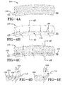
- the inlet device 78 as seen in FIGS. 1 , 2 , 4A through 4E includes an elongate outward porous filtering sleeve 100 encasing an internal intake tube 102.
- the outward sleeve 100 has an external geometry including a tubular inward air passage body.
- the sleeve 100 is configured to provide a bored tubular inward body 106 attached to an outward lobe body 104.
- the intake tube 102 has multiple air intake openings 108 therein which communicate with an axial air passageway extending through the tube 102.
- the inward body 106 is geometrically profiled to fit within the groove 58 with the lobe body 104 abutting against an outward surface of the tire sidewall.
- Air intake indicated by arrows 110 enters through the porous filtering sleeve 100 and the apertures 108 into the intake tube 102. Ends of the intake tube 102 are attached to the air tube 42 residing within the groove 58 and the tube 102 directs intake air into the tube 42 for pumping into the tire cavity.
- the pump assembly 14 comprises the air tube 42 and inlet and outlet devices 78, 80.
- Devices 78, 80 are affixed in-line to the air tube 42 at respective locations 180 degrees apart, is inserted into the groove 58.
- the groove 58 is located at a lower sidewall region of the tire that, when the tire 12 is mounted to the rim 16, positions the air tube 42 above the rim flange ends 26.
- FIG. 8B and 8C show the air tube 42 diametrically squeezed and collapsed to accommodate insertion into the groove 58.
- the air tube 42 fills the void represented by the groove 58.
- the air passageway 43 of the tube 42 elastically restores into an open condition to allow the flow of air along the tube during operation of the pump.
- the inlet device 78 and the outlet device 80 are positioned within the circumference of the circular air tube 42 generally 180 degrees apart.
- the tire 12 with the tube 42 positioned within groove 58 rotates in a direction of rotation 112, causing a footprint 114 to be formed against the ground surface 116.
- a compressive force 118 is directed into the tire from the footprint 114 and acts to flatten a segment 120 of the air tube passageway 43 opposite the footprint 114 as shown at numeral 120. Flattening of the segment 120 of the passageway 43 forces air from the segment along tube passageway 43 in the direction shown by arrow 122 toward the outlet device 80.
- the tube 42 will be sequentially flattened or squeezed opposite the tire footprint segment by segment in a direction opposite to the direction of tire rotation 112.
- a sequential flattening of the tube passageway 43 segment by segment will result and cause evacuated air from the flattened segments to be pumped in the direction 122 within tube passageway 43 to the outlet device 80 and from the outlet device 80 to the tire cavity as shown at 124.
- a valve system to regulate the flow of air to the cavity when the air pressure within the cavity falls to a prescribed level is shown and described in pending US-A- 2011/0272073 , and incorporated herein by reference.
- FIG. 5A shows the inflow of air into the inlet device 78 and then into the tube passageway 43 .
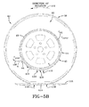
- FIG. 5B shows the orientation of the peristaltic pump assembly 14 in such a position.
- the tube 42 continues to be sequentially flattened segment by segment opposite the tire footprint by compressive force 118.
- Air is pumped in the clockwise direction 122 to the inlet device 78 where it is evacuated or exhausted outside of the tire.
- Passage of exhaust air as shown at 126 from the inlet device 78 is through the filter sleeve 100 which is formed of a cellular or porous material or composite. Flow of air through the sleeve 100 causes the sleeve 100 to be thus cleansed of debris or particulates. In the exhaust or reverse flow of air direction 126, the sleeve 100 is cleansed of trapped accumulated debris or particles within the porous medium.
- the outlet device With the evacuation of pumped air out of the inlet device 78, the outlet device is in the closed position and air does not flow to the tire cavity.
- the airflow resumes to the outlet device 80 and causes the pumped air to flow out and into the tire cavity 40. Air pressure within the tire cavity is thus maintained at a desired level.
- a preferred location for the air tube assembly 14 is as shown in FIGS. 5A , 5B , 6A , 6B , 7A and 7B .
- the tube 42 is located within the groove 58 in a lower region of the sidewall 30 of the tire 12. So located, the passageway 43 of the tube 42 is closed by compression strain bending the sidewall groove 58 within a rolling tire footprint as explained above.
- the location of the tube 42 in the sidewall 30 affords the user freedom of placement and avoids contact between the tube 42 and the rim 16.
- the higher placement of the tube 42 in the sidewall groove 58 uses the high deformation characteristics of this region of the sidewall as it passes through the tire footprint to close the tube.
- the subject invention provides a bi-directionally peristaltic pump for air maintenance of a tire.
- the circular air tube 42 flattens segment by segment and closes in the tire footprint 114.
- the air inlet device 78 may include an outer filter sleeve 100 formed of porous cellular material and thereby render device 78 as self-cleaning.
- the outlet device 80 employs a valve unit (see US-A- 2011/0272073 , incorporated herein by reference).
- the peristaltic pump assembly 14 pumps air under rotation of the tire in either direction, one half of a revolution pumping air to the tire cavity 40 and the other half of a revolution pumping air back out of the inlet device 68.
- the peristaltic pump assembly 14 may be used with a secondary tire pressure monitoring system (TPMS) (not shown) of conventional configuration that serves as a system fault detector.
- TPMS secondary tire pressure monitoring system
- the TPMS may be used to detect any fault in the self-inflation system of the tire assembly and alert the user of such a condition.
- the tire air maintenance system further incorporates a specified geometric shape to the tube 42 which locks into the groove 48 and prevents inadvertent dislodgement of the tube during tire operation.
- the tube 42 flattens into a compressed configuration and is inserted laterally into the groove 58. Upon removal of the compression forces, the tube 42 resumes its original shape and fills the void represented by groove 58.
- the tapered sides of the sidewalls defining the groove 58 in complement with the like-tapered external sides of the groove prevent any escape of the tube 42 through the smaller entryway of the groove 58.
- an elongate sidewall groove 58 extends into one or both of the tire sidewalls from an outward sidewall surface.
- Each sidewall groove 58 has an outer groove entry opening, a groove entry chamber axially inward from the groove entry opening defined by divergent entry chamber sidewalls, and a groove primary chamber axially inward from the groove entry chamber.
- the groove entry chamber sidewalls and the groove primary chamber sidewalls intersect to form at the intersection a detent channel.
- the elongate air tube 42 likewise in a preferably circular configuration, is positioned within the elongate sidewall groove in contact or in close proximity with the groove primary chamber sidewalls.
- the air tube has an external surface configuration corresponding with the sidewall configuration defining the elongate sidewall groove.
- the air tube body 42 has an external protrusion 57, 59 configured and dimensioned to register and seat within the detent channels 72, 74 of the sidewall groove, to hold the air tube 42 in place within the groove.
- the air tube 42 being formed of resilient material, is capable when subject to outward originating impinging force on the air tube of collapsing from an expanded unstressed configuration into a collapsed configuration to allow the tube to insert through the groove entry opening and expand outwardly once within the sidewall groove to its unstressed configuration.
- the method for inserting the configured air tube 42 into the sidewall groove 58 includes collapsing the air tube from an expanded unstressed configuration into a collapsed configuration to allow the tube to be inserted through the groove entry opening and, once inserted, expanded outwardly to its unstressed configuration.
Landscapes
- Engineering & Computer Science (AREA)
- Mechanical Engineering (AREA)
- Tires In General (AREA)
Abstract
Description
- The invention relates generally to tire comprising an air tube in a sidewall groove and to a method of assembling such an air tube within the tire, and, more specifically, to an air maintenance tire and a pumping tube assembly therefore and method of assembly.
- Normal air diffusion reduces tire pressure over time. The natural state of tires is under inflated. Accordingly, drivers must repeatedly act to maintain tire pressures or they will see reduced fuel economy, tire life and reduced vehicle braking and handling performance. Tire Pressure Monitoring Systems have been proposed to warn drivers when tire pressure is significantly low. Such systems, however, remain dependant upon the driver taking remedial action when warned to re-inflate a tire to recommended pressure. It is a desirable, therefore, to incorporate an air maintenance feature within a tire that will re-inflate the tire in order to compensate for any reduction in tire pressure over time without the need for driver intervention.
- The invention relates to a tire in accordance with claim 1 and to a method in accordance with claim 11.
- Dependent claims refer to preferred embodiments of the invention.
- In a preferred aspect of the invention, a tire is provided having an elongate sidewall groove extending into a first tire sidewall from an outward first sidewall surface; the sidewall groove having an outer groove entry opening, a groove entry chamber axially inward from the groove entry opening defined by divergent entry chamber sidewalls, and a groove primary chamber axially inward from the groove entry chamber. The groove entry chamber sidewalls and the groove primary chamber sidewalls intersect to form at the intersection a detent channel. An elongate air tube is positioned within the elongate sidewall groove in contact with the groove primary chamber sidewalls. The air tube has an external surface configuration corresponding with the sidewall configuration defining the elongate sidewall groove.
- In another preferred aspect, the air tube body has an external protrusion configured and dimensioned to register and seat within the detent channel of the sidewall groove.
- The air tube, in yet another preferred aspect of the invention, is formed of resilient material operative when subject to outward originating impinging force on the air tube to collapse from an expanded unstressed configuration into a collapsed configuration to allow the tube to insert through the groove entry opening and expand outwardly once within the sidewall groove to its unstressed configuration.
- According to another preferred aspect, a method for inserting a so-configured air tube into a sidewall groove of a tire is provided including collapsing the air tube from an expanded unstressed configuration into a collapsed configuration to allow the tube to insert through the groove entry opening and expanding the tube outwardly once within the sidewall groove to its unstressed configuration.
- "Axial" and "axially" means lines or directions that are parallel to the axis of rotation of the tire.
- "Footprint" means the contact patch or area of contact of the tire tread with a flat surface at zero speed and under normal load and pressure.
- "Groove" means an elongated void area in a tire wall that may extend circumferentially or laterally about the tire wall. The "groove width" is equal to its average width over its length. A grooves is sized to accommodate an air tube as described.
- "Peristaltic" means operating by means of wave-like contractions that propel contained matter, such as air, along tubular pathways.
- "Radial" and "radially" means directions radially toward or away from the axis of rotation of the tire.
- The invention will be described by way of example and with reference to the accompanying drawings in which:
-
FIG. 1 is an exploded isometric view of a tire, rim, and peristaltic tube assembly. -
FIG. 2 is a side view of the tire with the peristaltic tube assembly within a tire sidewall. -
FIG. 3A is an isometric view of an outlet device component showing of the tube assembly. -
FIG. 3B is a plan view of the outlet device. -
FIG. 3C is a section view through the outlet device taken along theline 3C-3C ofFIG. 3B . -
FIG. 4A is an isometric view of an inlet device component of the tube assembly. -
FIG. 4B is an isometric view of the inlet device with the filter sleeve in phantom. -
FIG. 4C is an isometric view of the inlet device component showing air intake schematically and the tube of the device in phantom. -
FIG. 4D is a sectional view through the inlet device taken along theline 4D-4D ofFIG. 4B . -
FIG. 4E is a section view through the inlet device taken along theline 4E-4E ofFIG. 4C . -
FIG. 5A is a side elevation view of the tire and peristaltic tube assembly shown schematically rotating against a road surface. -
FIG. 5B is a side elevation view of the tire and peristaltic tube assembly shown sequentially subsequent to the position ofFIG. 5A . -
FIG. 6A is a transverse section view through the tire and peristaltic tube assembly. -
FIG. 6B is an enlarged section view of the portion of the tire bead region, rim, and a non-collapsed peristaltic tube segment as identified inFIG. 6A . -
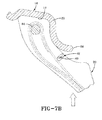
FIG. 7A is a transverse section view through the tire and peristaltic tube assembly with the tube in the collapsed configuration. -
FIG. 7B is an enlarged section view of a portion of the tire bead region, rim, and collapsed tube segment identified inFIG. 7A . -
FIG. 8A is an enlarged sectional exploded view of the tube and tube-receiving groove within the tire sidewall. -
FIGS. 8B and 8C are subsequent sequential sectional views toFIG. 8A showing insertion of the tube into the sidewall groove. -
FIG. 8D is a fragmented exploded view of the tube and sidewall groove corresponding toFIG. 8A . - Referring to
FIGS. 1 ,2 , and6A , atire assembly 10 includes atire 12, aperistaltic pump assembly 14, and atire rim 16. The tire mounts in conventional fashion to a pair ofrim mounting surfaces outer rim flanges flange end 26. Arim body 28 supports the tire assembly as shown. The tire is of conventional construction, having a pair ofsidewalls opposite bead areas tire tread region 38. The tire and rim enclose atire cavity 40. - As seen from
FIGS. 1 ,2 ,5A ,5B ,6A ,6B and8D theperistaltic pump assembly 14 includes anannular air tube 42 that encloses anannular passageway 43. Thetube 42 is formed of a resilient, flexible material such as plastic or rubber compounds that are capable of withstanding repeated deformation cycles wherein the tube is deformed into a flattened condition subject to external force and, upon removal of such force, returns to an original condition. Thetube passageway 43 is generally elliptical in section and is of a diameter sufficient to operatively pass a volume of air sufficient for the purposes described herein and allowing a positioning of the tube in an operable location within the tire assembly as will be described. In the configuration shown, thetube 42 is elongate and circular. Thetube 42 is asymmetric about an elongate major axis and is constructed having an outwardflat end surface 44, a tapered protrudingoutward portion 46, and amain body portion 48. The protrudingportion 46 of thetube 42 is defined bybeveled surfaces flat tube surface 44 to an arcuateoutward surface 56 of themain body portion 48 of thetube 42. At the intersection of thebeveled surfaces outer surface 56 of the main body portion 48 a pair ofshoulders tube 42 on opposite respective sides of protrudingportion 46. - An
elongate groove 58 is formed to extend into an axially outward surface of a sidewall such assidewall 30, preferably in the geometric form of an annular ring. The other sidewall may be grooved or both sidewalls if so desired. Thegroove 58 has an internal sectional profile complementary with the external geometry of thetube 42, and includes anentry opening 60 exposed to theouter surface 61 of thesidewall 30. Thegroove 58 is formed to provide anentry chamber 62 adjacent to and axially inward of theopening 60 and aprimary chamber 64 axially inward from and adjacent to theentry chamber 62. Theentry chamber 62 is defined bybeveled sidewalls opening 60 and the primary chamber is defined by primary chamber sidewalls 70. At the intersection of thebeveled sidewalls inward sidewalls 70 of the primary chamber a pair of shoulders detentchannels groove 58 on opposite respective sides of the groove. - As referenced in
FIG 8A , thetube 42 has a transverse sectional width length L1 within a preferred range of 3.65 to 3.8 mm; a preferred height of D1 within a range of 2.2 to 3.8 mm; a trailing end preferred width of D3 within a range of 0.8 to 1 mm. Theinternal air passageway 43 is generally elliptical having a length L2 along a major axis within a preferred range of 2.2 to 2.3 mm, and a width D2 along a transverse axis within a preferred range of 0.5 to 0.9 mm. Thetube 42 has an axial distance L3 between theend surface 44 and the center of thepassageway 43 lying within a preferred range of 1.8 to 2 mm. - The
groove 58 is of complementary internal geometry to accommodate close receipt of thetube 42. As shown inFIG. 8A , thegroove 58 is dimensionally compatible for receipt of thetube 42, and incorporates dimensions D1, D3, L1, L3 within the preferred ranges previously set forth with respect to thetube 42. Theprimary chamber 64 is radiussed by a radius R1 lying within a preferred range of 1.1 to 1.9 mm. The beveled surfaces 66, 68 and complementarydivergent surfaces tube 42 are sloped at generally an acute angle of approximately 45 degrees. - As best seen from
FIGS. 8A-D , insertion of thetube 42 into thegroove 58 is initiated by axially aligning thetube 42 with the entry opening 60 of thegroove 58; compressing thetube 42 in the direction ofarrows 76 so as to reduce the groove height, whereby collapsing thegroove air passageway 43; inserting thetube 42 laterally through thegroove opening 60 and into the space defined byentry chamber 62 andprimary chamber 64; removing the compression force atarrows 76, thereby freeing thetube 42 to expand outward into its nominal unstressed configuration ofFIGS. 8A ,8C , and8D and occupy thegroove 58. Thetube 42 is thus located within thegroove 58 with external surfaces of the groove disposed adjacent to corresponding complementary sidewalls defining thegroove 58. In the expanded, unstressed condition of the tube, theshoulders tube 42 register within thedetent channels divergent sides divergent sidewalls tube 42 within thegroove 58. - With reference to
FIGS. 1 ,2 ,3A through 3C and4A through E , theperistaltic pump assembly 14 further includes aninlet device 78 and anoutlet device 80 preferably spaced apart approximately 180 degrees at respective locations along thecircumferential air tube 42. Theoutlet device 80, as shown inFIGS. 3A through 3C , has a T-shaped configuration in whichconduits tire cavity 40. Anoutlet device housing 86 containsconduit arm extensions respective conduits conduit arms barbs air tube 42 in the assembled condition. Thehousing 86 is formed having an external geometry that complements thegroove 58 and includes aflat side 96 along a generally oblongbody 98. So configured, thehousing 86 is capable of close receipt into thegroove 58 at its intended location. - The
inlet device 78 as seen inFIGS. 1 ,2 ,4A through 4E includes an elongate outwardporous filtering sleeve 100 encasing aninternal intake tube 102. Theoutward sleeve 100 has an external geometry including a tubular inward air passage body. Thesleeve 100 is configured to provide a bored tubularinward body 106 attached to anoutward lobe body 104. Theintake tube 102 has multipleair intake openings 108 therein which communicate with an axial air passageway extending through thetube 102. Theinward body 106 is geometrically profiled to fit within thegroove 58 with thelobe body 104 abutting against an outward surface of the tire sidewall. Air intake indicated byarrows 110 enters through theporous filtering sleeve 100 and theapertures 108 into theintake tube 102. Ends of theintake tube 102 are attached to theair tube 42 residing within thegroove 58 and thetube 102 directs intake air into thetube 42 for pumping into the tire cavity. - As will be appreciated from
FIGS. 1 ,2 ,6A ,6B ,7A and7B , thepump assembly 14 comprises theair tube 42 and inlet andoutlet devices Devices air tube 42 at respective locations 180 degrees apart, is inserted into thegroove 58. Thegroove 58 is located at a lower sidewall region of the tire that, when thetire 12 is mounted to therim 16, positions theair tube 42 above the rim flange ends 26.FIG. 8B and 8C show theair tube 42 diametrically squeezed and collapsed to accommodate insertion into thegroove 58. Upon full insertion, as shown inFIG. 8C , theair tube 42 fills the void represented by thegroove 58. Once fully inserted, theair passageway 43 of thetube 42 elastically restores into an open condition to allow the flow of air along the tube during operation of the pump. - With continued reference to Referring to
FIGS. 1 ,2 ,5A ,5B ,6A ,6B ,7A ,7B , theinlet device 78 and theoutlet device 80 are positioned within the circumference of thecircular air tube 42 generally 180 degrees apart. Thetire 12 with thetube 42 positioned withingroove 58 rotates in a direction ofrotation 112, causing afootprint 114 to be formed against theground surface 116. Acompressive force 118 is directed into the tire from thefootprint 114 and acts to flatten asegment 120 of theair tube passageway 43 opposite thefootprint 114 as shown atnumeral 120. Flattening of thesegment 120 of thepassageway 43 forces air from the segment alongtube passageway 43 in the direction shown byarrow 122 toward theoutlet device 80. - As the tire continues to rotate in
direction 112 along theground surface 116, thetube 42 will be sequentially flattened or squeezed opposite the tire footprint segment by segment in a direction opposite to the direction oftire rotation 112. A sequential flattening of thetube passageway 43 segment by segment will result and cause evacuated air from the flattened segments to be pumped in thedirection 122 withintube passageway 43 to theoutlet device 80 and from theoutlet device 80 to the tire cavity as shown at 124. A valve system to regulate the flow of air to the cavity when the air pressure within the cavity falls to a prescribed level is shown and described in pendingUS-A- 2011/0272073 , and incorporated herein by reference. - With the tire rotating in
direction 112, flattened tube segments are sequentially refilled by air flowing into theinlet device 78 in thedirection 110 as shown byFIG. 5A . The inflow of air into theinlet device 78 and then into thetube passageway 43 continues until theoutlet device 80, rotating counterclockwise as shown with the tire rotation, passes thetire footprint 114.FIG. 5B shows the orientation of theperistaltic pump assembly 14 in such a position. In the position shown, thetube 42 continues to be sequentially flattened segment by segment opposite the tire footprint bycompressive force 118. Air is pumped in theclockwise direction 122 to theinlet device 78 where it is evacuated or exhausted outside of the tire. Passage of exhaust air as shown at 126 from theinlet device 78 is through thefilter sleeve 100 which is formed of a cellular or porous material or composite. Flow of air through thesleeve 100 causes thesleeve 100 to be thus cleansed of debris or particulates. In the exhaust or reverse flow ofair direction 126, thesleeve 100 is cleansed of trapped accumulated debris or particles within the porous medium. With the evacuation of pumped air out of theinlet device 78, the outlet device is in the closed position and air does not flow to the tire cavity. When the tire rotates further incounterclockwise direction 112 until theinlet device 78 passes the tire footprint 114 (as shown inFIG. 5A ), the airflow resumes to theoutlet device 80 and causes the pumped air to flow out and into thetire cavity 40. Air pressure within the tire cavity is thus maintained at a desired level. - The above-described cycle is then repeated for each tire revolution, half of each rotation resulting in pumped air going to the tire cavity and half of the rotation the pumped air is directed back out the inlet
device filter sleeve 100 to self-clean the filter. It will be appreciated that while the direction ofrotation 112 of thetire 12 is as shown inFIGS. 5A and5B to be counterclockwise, the subject tire assembly and itsperistaltic pump assembly 14 will function in like manner in a (clockwise) reverse direction of rotation as well. The peristaltic pump is accordingly bi-directional and equally functional with the tire assembly moving in a forward or a reverse direction of rotation. - A preferred location for the
air tube assembly 14 is as shown inFIGS. 5A ,5B ,6A ,6B ,7A and7B . Thetube 42 is located within thegroove 58 in a lower region of thesidewall 30 of thetire 12. So located, thepassageway 43 of thetube 42 is closed by compression strain bending thesidewall groove 58 within a rolling tire footprint as explained above. The location of thetube 42 in thesidewall 30 affords the user freedom of placement and avoids contact between thetube 42 and therim 16. The higher placement of thetube 42 in thesidewall groove 58 uses the high deformation characteristics of this region of the sidewall as it passes through the tire footprint to close the tube. - From the forgoing, it will be appreciated that the subject invention provides a bi-directionally peristaltic pump for air maintenance of a tire. The
circular air tube 42 flattens segment by segment and closes in thetire footprint 114. Theair inlet device 78 may include anouter filter sleeve 100 formed of porous cellular material and thereby renderdevice 78 as self-cleaning. Theoutlet device 80 employs a valve unit (seeUS-A- 2011/0272073 , incorporated herein by reference). Theperistaltic pump assembly 14 pumps air under rotation of the tire in either direction, one half of a revolution pumping air to thetire cavity 40 and the other half of a revolution pumping air back out of theinlet device 68. Theperistaltic pump assembly 14 may be used with a secondary tire pressure monitoring system (TPMS) (not shown) of conventional configuration that serves as a system fault detector. The TPMS may be used to detect any fault in the self-inflation system of the tire assembly and alert the user of such a condition. - The tire air maintenance system further incorporates a specified geometric shape to the
tube 42 which locks into thegroove 48 and prevents inadvertent dislodgement of the tube during tire operation. Thetube 42 flattens into a compressed configuration and is inserted laterally into thegroove 58. Upon removal of the compression forces, thetube 42 resumes its original shape and fills the void represented bygroove 58. The tapered sides of the sidewalls defining thegroove 58 in complement with the like-tapered external sides of the groove prevent any escape of thetube 42 through the smaller entryway of thegroove 58. - It will thus be appreciated that, in the subject invention, an
elongate sidewall groove 58, preferably in a circular configuration, extends into one or both of the tire sidewalls from an outward sidewall surface. Eachsidewall groove 58 has an outer groove entry opening, a groove entry chamber axially inward from the groove entry opening defined by divergent entry chamber sidewalls, and a groove primary chamber axially inward from the groove entry chamber. The groove entry chamber sidewalls and the groove primary chamber sidewalls intersect to form at the intersection a detent channel. Theelongate air tube 42, likewise in a preferably circular configuration, is positioned within the elongate sidewall groove in contact or in close proximity with the groove primary chamber sidewalls. The air tube has an external surface configuration corresponding with the sidewall configuration defining the elongate sidewall groove. - The
air tube body 42 has anexternal protrusion detent channels air tube 42 in place within the groove. Theair tube 42, being formed of resilient material, is capable when subject to outward originating impinging force on the air tube of collapsing from an expanded unstressed configuration into a collapsed configuration to allow the tube to insert through the groove entry opening and expand outwardly once within the sidewall groove to its unstressed configuration. The method for inserting the configuredair tube 42 into thesidewall groove 58 includes collapsing the air tube from an expanded unstressed configuration into a collapsed configuration to allow the tube to be inserted through the groove entry opening and, once inserted, expanded outwardly to its unstressed configuration.
Claims (14)
- A tire comprising a tire cavity (40); a first and a second sidewall (30, 32) extending to a tire tread region (38); an elongate sidewall groove (58) extending into the first tire sidewall (30) from an outward first sidewall surface, the sidewall groove (58) having an outer groove entry opening (60), a groove entry chamber (62) axially inward from the groove entry opening (60) defined by divergent entry chamber sidewalls (66, 68), and a groove primary chamber (64) axially inward from the groove entry chamber (62) defined by primary chamber sidewalls (70), the groove entry chamber sidewalls (66, 68) and the groove primary chamber sidewalls (70) intersecting and forming at the intersection a detent channel (72, 74) substantially extending a longitudinal length of the sidewall groove (58); and an elongate air tube (42) positioned within the elongate sidewall groove (58) in at least partial contacting engagement with the groove primary chamber sidewalls (70), the air tube (42) having an internal air passageway (43).
- The tire of claim 1, wherein the air tube (42) has a primary air tube body, the primary air tube body having an external surface configuration defined by primary air tube body external sides substantially adjacent and extending in parallel with the groove primary chamber sidewalls.
- The tire of claim 2, wherein the primary air tube body having an axially outward air tube body protrusion, the air tube body protrusion having an external surface configuration defined by protrusion external sides substantially adjacent and extending in parallel with the groove entry chamber sidewalls.
- The tire of claim 3, wherein the primary air tube body external sides and the air tube body protrusion external sides intersect and form at the intersection a shoulder residing within the detent channel (72, 74) of the sidewall groove (58).
- The tire of at least one of the previous claims, wherein the air tube (42) and the sidewall groove (58) extend along a common substantially circular path.
- The tire of at least one of the previous claims, wherein the air tube (42) is formed of resilient material operative when subject to outward originating impinging force on the air tube (42) to collapse from an expanded unstressed configuration into a collapsed configuration wherein the air passageway (43) is at least locally substantially closed, and wherein the air tube (42) is operative to resiliently resume the expanded unstressed configuration upon removal of the impinging force.
- The tire of claim 6, wherein the air tube (42) in the expanded unstressed configuration has an expanded transverse dimension greater than a diametric dimension of the groove entry opening (60) and the air tube (42) in the collapsed configuration has a collapsed transverse dimension less than the diametric dimension of the groove entry opening (60).
- The tire of at least one of the previous claims, wherein the air tube (42) substantially occupies a volumetric entirety of the sidewall groove (58).
- The tire of at least one of the previous claims, wherein the air passageway (43) is substantially elliptical in section along a longitudinal axis oriented in an axial direction within the sidewall groove (58).
- The tire of at least one of the previous claims, wherein the air tube (42) is asymmetrical in a radial tire direction.
- A method of assembling an elongate air tube (42) within a tire (12), the tire (12) having a tire cavity (40), a first and a second sidewall (30, 32) extending to a tire tread region (38), the method comprising:deploying an elongate sidewall groove (58) into the first tire sidewall (30) from an outward first sidewall surface, the sidewall groove having an outer groove entry opening (60), a groove entry chamber (62) axially inward from the groove entry opening (60) defined by divergent entry chamber sidewalls (66, 68), and a groove primary chamber (64) axially inward from the groove entry chamber (62) defined by primary chamber sidewalls (70), the groove entry chamber sidewalls (66, 68) and the groove primary chamber sidewalls (70) intersecting;advancing an elongate air tube (42) laterally relative to an air tube center axis and toward the outer groove entry opening (60), the air tube (42) having an internal air passageway (43) and the air tube (42) having an air tube body formed of resilient material operative when subject to outward originating impinging forces on the air tube body to collapse from an expanded unstressed configuration into a collapsed configuration wherein the air passageway (43) is at least locally substantially closed;applying an impinging force on the air tube body to collapse the air tube body into the collapsed configuration wherein the air tube body having a reduced diametric dimension;inserting the air tube body in the collapsed configuration through the sidewall groove entry opening (60) and into the groove primary chamber (64); andremoving the impinging force;expanding the air tube body within the groove primary chamber (64) to the expanded configuration within the sidewall groove (58).
- The method of claim 11, further comprising:forming at the intersection of the groove entry chamber sidewalls (66, 68) and the groove primary chamber sidewalls (70) a detent channel (72, 74); andpositioning an air tube body protrusion within the detent channel (72, 74) with the air tube (42) located within the sidewall groove (58) in the expanded configuration.
- The method of claim 11 or 12, comprising expanding the air tube body within the sidewall groove (58) to substantially occupy a volumetric entirety of the sidewall groove (58).
- The method of claim 11, comprising orienting a longitudinal axis of the air passageway (43) in an axial direction within the sidewall groove (58).
Applications Claiming Priority (1)
| Application Number | Priority Date | Filing Date | Title |
|---|---|---|---|
| US13/252,242 US8851132B2 (en) | 2011-10-04 | 2011-10-04 | Air maintenance tire and pumping tube assembly and method |
Publications (2)
| Publication Number | Publication Date |
|---|---|
| EP2578420A1 true EP2578420A1 (en) | 2013-04-10 |
| EP2578420B1 EP2578420B1 (en) | 2017-03-22 |
Family
ID=46970130
Family Applications (1)
| Application Number | Title | Priority Date | Filing Date |
|---|---|---|---|
| EP12187039.8A Active EP2578420B1 (en) | 2011-10-04 | 2012-10-02 | Tire comprising a tube assembly and method of assembling an elongate air tube within a tire |
Country Status (5)
| Country | Link |
|---|---|
| US (2) | US8851132B2 (en) |
| EP (1) | EP2578420B1 (en) |
| JP (1) | JP6001409B2 (en) |
| CN (1) | CN103029527B (en) |
| BR (1) | BR102012025290A2 (en) |
Cited By (4)
| Publication number | Priority date | Publication date | Assignee | Title |
|---|---|---|---|---|
| EP2664467A1 (en) * | 2012-05-14 | 2013-11-20 | The Goodyear Tire & Rubber Company | Peristaltic tube air maintenance tire assembly and method |
| US9205712B2 (en) | 2013-12-16 | 2015-12-08 | The Goodyear Tire & Rubber Company | Snap-in inlet and connection method for air maintenance tire |
| EP2987658A1 (en) * | 2014-08-20 | 2016-02-24 | The Goodyear Tire & Rubber Company | Air maintenance tire and method of manufacturing |
| CN108237852A (en) * | 2016-12-23 | 2018-07-03 | 锦湖轮胎株式会社 | Tire with self-inflator |
Families Citing this family (11)
| Publication number | Priority date | Publication date | Assignee | Title |
|---|---|---|---|---|
| FR2977828B1 (en) * | 2011-07-13 | 2013-08-16 | Michelin Soc Tech | PNEUMATIC FOLDING MACHINE, FOLDING METHOD AND USE |
| US9333816B2 (en) * | 2013-11-05 | 2016-05-10 | The Goodyear Tire & Rubber Company | Air maintenance tire and valve assembly and method |
| US9272586B2 (en) * | 2013-11-05 | 2016-03-01 | The Goodyear Tire & Rubber Company | Valve stem-based air maintenance tire and method |
| US9233583B2 (en) * | 2013-12-11 | 2016-01-12 | The Goodyear Tire & Rubber Company | Tire apparatus |
| US9365084B2 (en) * | 2013-12-11 | 2016-06-14 | The Goodyear Tire & Rubber Company | Self-inflating tire and pressure regulator |
| US9783015B2 (en) | 2014-08-12 | 2017-10-10 | The Goodyear Tire & Rubber Company | Control regulator and pumping system for an air maintenance tire |
| US9744816B2 (en) | 2014-08-12 | 2017-08-29 | The Goodyear Tire & Rubber Company | Air maintenance tire |
| US20160375731A1 (en) * | 2015-06-29 | 2016-12-29 | The Goodyear Tire & Rubber Company | Air maintenance pumping assembly and tire |
| US10773559B2 (en) * | 2016-11-08 | 2020-09-15 | The Goodyear Tire & Rubber Company | Air maintenance tire |
| US11285764B2 (en) | 2016-12-22 | 2022-03-29 | The Goodyear Tire & Rubber Company | Control valve for an air maintenance tire |
| US10807422B2 (en) | 2016-12-22 | 2020-10-20 | The Goodyear Tire & Rubber Company | Inlet control valve for an air maintenance tire |
Citations (4)
| Publication number | Priority date | Publication date | Assignee | Title |
|---|---|---|---|---|
| US20040112495A1 (en) * | 2002-12-09 | 2004-06-17 | Curtis Arlen Weise | Self inflating tire |
| WO2007134556A1 (en) * | 2006-05-23 | 2007-11-29 | Coda Development, S.R.O. | A chamber of a peristaltic pump for tire pressure adjustment |
| EP2338703A2 (en) * | 2009-12-21 | 2011-06-29 | The Goodyear Tire & Rubber Company | Self-inflating tire assembly |
| US20110272073A1 (en) | 2010-05-07 | 2011-11-10 | Robert Allen Losey | Self-inflating tire assembly |
Family Cites Families (9)
| Publication number | Priority date | Publication date | Assignee | Title |
|---|---|---|---|---|
| US1050886A (en) * | 1910-02-23 | 1913-01-21 | Anson B Wetherell | Vehicle-tire. |
| GB1086512A (en) * | 1964-02-24 | 1967-10-11 | Ronald Leslie Sheppard | Improvements in or relating to pneumatic tyres |
| US3867973A (en) | 1973-01-30 | 1975-02-25 | United Aircraft Prod | Pneumatic tire with embedded ring means |
| US3833041A (en) * | 1973-10-11 | 1974-09-03 | Aerojet General Co | Tire inflator |
| WO2003049958A1 (en) * | 2001-12-11 | 2003-06-19 | Frantisek Hrabal | Device for monitoring, maintenance and adjustment of pressure in a tyre |
| CZ299520B6 (en) * | 2003-04-04 | 2008-08-20 | Hrabal Frantiueek | Process for producing a chamber of a self-inflating pneumatic tyre |
| DE10335244A1 (en) * | 2003-08-01 | 2005-03-10 | Bayerische Motoren Werke Ag | Device for air filling a rotating pneumatic tire |
| US20050092411A1 (en) * | 2003-10-31 | 2005-05-05 | O'brien John M. | Tire having expandable tread portion |
| US8322036B2 (en) * | 2010-11-22 | 2012-12-04 | The Goodyear Tire & Rubber Company | Method of manufacturing a self-inflating tire |
-
2011
- 2011-10-04 US US13/252,242 patent/US8851132B2/en active Active
-
2012
- 2012-09-28 CN CN201210366530.9A patent/CN103029527B/en not_active Expired - Fee Related
- 2012-10-02 EP EP12187039.8A patent/EP2578420B1/en active Active
- 2012-10-03 BR BRBR102012025290-2A patent/BR102012025290A2/en not_active IP Right Cessation
- 2012-10-04 JP JP2012221838A patent/JP6001409B2/en not_active Expired - Fee Related
-
2014
- 2014-09-15 US US14/486,121 patent/US9073395B2/en active Active
Patent Citations (4)
| Publication number | Priority date | Publication date | Assignee | Title |
|---|---|---|---|---|
| US20040112495A1 (en) * | 2002-12-09 | 2004-06-17 | Curtis Arlen Weise | Self inflating tire |
| WO2007134556A1 (en) * | 2006-05-23 | 2007-11-29 | Coda Development, S.R.O. | A chamber of a peristaltic pump for tire pressure adjustment |
| EP2338703A2 (en) * | 2009-12-21 | 2011-06-29 | The Goodyear Tire & Rubber Company | Self-inflating tire assembly |
| US20110272073A1 (en) | 2010-05-07 | 2011-11-10 | Robert Allen Losey | Self-inflating tire assembly |
Cited By (5)
| Publication number | Priority date | Publication date | Assignee | Title |
|---|---|---|---|---|
| EP2664467A1 (en) * | 2012-05-14 | 2013-11-20 | The Goodyear Tire & Rubber Company | Peristaltic tube air maintenance tire assembly and method |
| US9056533B2 (en) | 2012-05-14 | 2015-06-16 | The Goodyear Tire & Rubber Company | Peristaltic tube air maintenance tire assembly and method |
| US9205712B2 (en) | 2013-12-16 | 2015-12-08 | The Goodyear Tire & Rubber Company | Snap-in inlet and connection method for air maintenance tire |
| EP2987658A1 (en) * | 2014-08-20 | 2016-02-24 | The Goodyear Tire & Rubber Company | Air maintenance tire and method of manufacturing |
| CN108237852A (en) * | 2016-12-23 | 2018-07-03 | 锦湖轮胎株式会社 | Tire with self-inflator |
Also Published As
| Publication number | Publication date |
|---|---|
| JP2013079067A (en) | 2013-05-02 |
| CN103029527A (en) | 2013-04-10 |
| US20150000136A1 (en) | 2015-01-01 |
| US20130081745A1 (en) | 2013-04-04 |
| CN103029527B (en) | 2015-05-27 |
| BR102012025290A2 (en) | 2013-12-17 |
| JP6001409B2 (en) | 2016-10-05 |
| US9073395B2 (en) | 2015-07-07 |
| US8851132B2 (en) | 2014-10-07 |
| EP2578420B1 (en) | 2017-03-22 |
Similar Documents
| Publication | Publication Date | Title |
|---|---|---|
| EP2578420B1 (en) | Tire comprising a tube assembly and method of assembling an elongate air tube within a tire | |
| EP2546083B1 (en) | Air maintenance pumping tube and tire assembly | |
| EP2543524B1 (en) | Air maintenance pumping assembly and tire | |
| EP2565060B1 (en) | Self-inflating tire | |
| EP2343200B1 (en) | Self-inflating tire | |
| EP2565059B1 (en) | Pneumatic tire | |
| EP2692549B1 (en) | Pneumatic tire comprising a filter | |
| EP2338703B1 (en) | Self-inflating tire assembly | |
| EP2567834B1 (en) | Tire comprising an air passageway in a sidewall groove | |
| EP2746072B1 (en) | Compact valve system for self-inflating tire | |
| EP2730437A1 (en) | Securing to a pneumatic tire | |
| US20150375575A1 (en) | Vein pump assembly for air maintenance tire | |
| EP2883718A1 (en) | Self-inflating tire with hybrid pump | |
| EP3028881B1 (en) | Filter for a pneumatic tire | |
| EP3112192A1 (en) | Tire | |
| EP2957439A1 (en) | Air maintenance pumping system and tire | |
| EP2987658A1 (en) | Air maintenance tire and method of manufacturing |
Legal Events
| Date | Code | Title | Description |
|---|---|---|---|
| PUAI | Public reference made under article 153(3) epc to a published international application that has entered the european phase |
Free format text: ORIGINAL CODE: 0009012 |
|
| AK | Designated contracting states |
Kind code of ref document: A1 Designated state(s): AL AT BE BG CH CY CZ DE DK EE ES FI FR GB GR HR HU IE IS IT LI LT LU LV MC MK MT NL NO PL PT RO RS SE SI SK SM TR |
|
| AX | Request for extension of the european patent |
Extension state: BA ME |
|
| 17P | Request for examination filed |
Effective date: 20131010 |
|
| RBV | Designated contracting states (corrected) |
Designated state(s): AL AT BE BG CH CY CZ DE DK EE ES FI FR GB GR HR HU IE IS IT LI LT LU LV MC MK MT NL NO PL PT RO RS SE SI SK SM TR |
|
| 17Q | First examination report despatched |
Effective date: 20150521 |
|
| GRAP | Despatch of communication of intention to grant a patent |
Free format text: ORIGINAL CODE: EPIDOSNIGR1 |
|
| INTG | Intention to grant announced |
Effective date: 20161010 |
|
| GRAS | Grant fee paid |
Free format text: ORIGINAL CODE: EPIDOSNIGR3 |
|
| GRAA | (expected) grant |
Free format text: ORIGINAL CODE: 0009210 |
|
| AK | Designated contracting states |
Kind code of ref document: B1 Designated state(s): AL AT BE BG CH CY CZ DE DK EE ES FI FR GB GR HR HU IE IS IT LI LT LU LV MC MK MT NL NO PL PT RO RS SE SI SK SM TR |
|
| REG | Reference to a national code |
Ref country code: GB Ref legal event code: FG4D |
|
| REG | Reference to a national code |
Ref country code: CH Ref legal event code: EP |
|
| REG | Reference to a national code |
Ref country code: AT Ref legal event code: REF Ref document number: 877350 Country of ref document: AT Kind code of ref document: T Effective date: 20170415 |
|
| REG | Reference to a national code |
Ref country code: IE Ref legal event code: FG4D |
|
| REG | Reference to a national code |
Ref country code: DE Ref legal event code: R096 Ref document number: 602012030067 Country of ref document: DE |
|
| REG | Reference to a national code |
Ref country code: NL Ref legal event code: MP Effective date: 20170322 |
|
| PG25 | Lapsed in a contracting state [announced via postgrant information from national office to epo] |
Ref country code: FI Free format text: LAPSE BECAUSE OF FAILURE TO SUBMIT A TRANSLATION OF THE DESCRIPTION OR TO PAY THE FEE WITHIN THE PRESCRIBED TIME-LIMIT Effective date: 20170322 Ref country code: GR Free format text: LAPSE BECAUSE OF FAILURE TO SUBMIT A TRANSLATION OF THE DESCRIPTION OR TO PAY THE FEE WITHIN THE PRESCRIBED TIME-LIMIT Effective date: 20170623 Ref country code: HR Free format text: LAPSE BECAUSE OF FAILURE TO SUBMIT A TRANSLATION OF THE DESCRIPTION OR TO PAY THE FEE WITHIN THE PRESCRIBED TIME-LIMIT Effective date: 20170322 Ref country code: LT Free format text: LAPSE BECAUSE OF FAILURE TO SUBMIT A TRANSLATION OF THE DESCRIPTION OR TO PAY THE FEE WITHIN THE PRESCRIBED TIME-LIMIT Effective date: 20170322 Ref country code: NO Free format text: LAPSE BECAUSE OF FAILURE TO SUBMIT A TRANSLATION OF THE DESCRIPTION OR TO PAY THE FEE WITHIN THE PRESCRIBED TIME-LIMIT Effective date: 20170622 |
|
| REG | Reference to a national code |
Ref country code: LT Ref legal event code: MG4D |
|
| REG | Reference to a national code |
Ref country code: AT Ref legal event code: MK05 Ref document number: 877350 Country of ref document: AT Kind code of ref document: T Effective date: 20170322 |
|
| PG25 | Lapsed in a contracting state [announced via postgrant information from national office to epo] |
Ref country code: LV Free format text: LAPSE BECAUSE OF FAILURE TO SUBMIT A TRANSLATION OF THE DESCRIPTION OR TO PAY THE FEE WITHIN THE PRESCRIBED TIME-LIMIT Effective date: 20170322 Ref country code: SE Free format text: LAPSE BECAUSE OF FAILURE TO SUBMIT A TRANSLATION OF THE DESCRIPTION OR TO PAY THE FEE WITHIN THE PRESCRIBED TIME-LIMIT Effective date: 20170322 Ref country code: RS Free format text: LAPSE BECAUSE OF FAILURE TO SUBMIT A TRANSLATION OF THE DESCRIPTION OR TO PAY THE FEE WITHIN THE PRESCRIBED TIME-LIMIT Effective date: 20170322 Ref country code: BG Free format text: LAPSE BECAUSE OF FAILURE TO SUBMIT A TRANSLATION OF THE DESCRIPTION OR TO PAY THE FEE WITHIN THE PRESCRIBED TIME-LIMIT Effective date: 20170622 |
|
| REG | Reference to a national code |
Ref country code: FR Ref legal event code: PLFP Year of fee payment: 6 |
|
| PG25 | Lapsed in a contracting state [announced via postgrant information from national office to epo] |
Ref country code: NL Free format text: LAPSE BECAUSE OF FAILURE TO SUBMIT A TRANSLATION OF THE DESCRIPTION OR TO PAY THE FEE WITHIN THE PRESCRIBED TIME-LIMIT Effective date: 20170322 |
|
| PG25 | Lapsed in a contracting state [announced via postgrant information from national office to epo] |
Ref country code: SK Free format text: LAPSE BECAUSE OF FAILURE TO SUBMIT A TRANSLATION OF THE DESCRIPTION OR TO PAY THE FEE WITHIN THE PRESCRIBED TIME-LIMIT Effective date: 20170322 Ref country code: RO Free format text: LAPSE BECAUSE OF FAILURE TO SUBMIT A TRANSLATION OF THE DESCRIPTION OR TO PAY THE FEE WITHIN THE PRESCRIBED TIME-LIMIT Effective date: 20170322 Ref country code: AT Free format text: LAPSE BECAUSE OF FAILURE TO SUBMIT A TRANSLATION OF THE DESCRIPTION OR TO PAY THE FEE WITHIN THE PRESCRIBED TIME-LIMIT Effective date: 20170322 Ref country code: EE Free format text: LAPSE BECAUSE OF FAILURE TO SUBMIT A TRANSLATION OF THE DESCRIPTION OR TO PAY THE FEE WITHIN THE PRESCRIBED TIME-LIMIT Effective date: 20170322 Ref country code: CZ Free format text: LAPSE BECAUSE OF FAILURE TO SUBMIT A TRANSLATION OF THE DESCRIPTION OR TO PAY THE FEE WITHIN THE PRESCRIBED TIME-LIMIT Effective date: 20170322 Ref country code: ES Free format text: LAPSE BECAUSE OF FAILURE TO SUBMIT A TRANSLATION OF THE DESCRIPTION OR TO PAY THE FEE WITHIN THE PRESCRIBED TIME-LIMIT Effective date: 20170322 |
|
| PG25 | Lapsed in a contracting state [announced via postgrant information from national office to epo] |
Ref country code: PL Free format text: LAPSE BECAUSE OF FAILURE TO SUBMIT A TRANSLATION OF THE DESCRIPTION OR TO PAY THE FEE WITHIN THE PRESCRIBED TIME-LIMIT Effective date: 20170322 Ref country code: SM Free format text: LAPSE BECAUSE OF FAILURE TO SUBMIT A TRANSLATION OF THE DESCRIPTION OR TO PAY THE FEE WITHIN THE PRESCRIBED TIME-LIMIT Effective date: 20170322 Ref country code: IS Free format text: LAPSE BECAUSE OF FAILURE TO SUBMIT A TRANSLATION OF THE DESCRIPTION OR TO PAY THE FEE WITHIN THE PRESCRIBED TIME-LIMIT Effective date: 20170722 Ref country code: PT Free format text: LAPSE BECAUSE OF FAILURE TO SUBMIT A TRANSLATION OF THE DESCRIPTION OR TO PAY THE FEE WITHIN THE PRESCRIBED TIME-LIMIT Effective date: 20170724 |
|
| REG | Reference to a national code |
Ref country code: DE Ref legal event code: R097 Ref document number: 602012030067 Country of ref document: DE |
|
| PLBE | No opposition filed within time limit |
Free format text: ORIGINAL CODE: 0009261 |
|
| STAA | Information on the status of an ep patent application or granted ep patent |
Free format text: STATUS: NO OPPOSITION FILED WITHIN TIME LIMIT |
|
| PG25 | Lapsed in a contracting state [announced via postgrant information from national office to epo] |
Ref country code: DK Free format text: LAPSE BECAUSE OF FAILURE TO SUBMIT A TRANSLATION OF THE DESCRIPTION OR TO PAY THE FEE WITHIN THE PRESCRIBED TIME-LIMIT Effective date: 20170322 |
|
| 26N | No opposition filed |
Effective date: 20180102 |
|
| PG25 | Lapsed in a contracting state [announced via postgrant information from national office to epo] |
Ref country code: SI Free format text: LAPSE BECAUSE OF FAILURE TO SUBMIT A TRANSLATION OF THE DESCRIPTION OR TO PAY THE FEE WITHIN THE PRESCRIBED TIME-LIMIT Effective date: 20170322 |
|
| PG25 | Lapsed in a contracting state [announced via postgrant information from national office to epo] |
Ref country code: MC Free format text: LAPSE BECAUSE OF FAILURE TO SUBMIT A TRANSLATION OF THE DESCRIPTION OR TO PAY THE FEE WITHIN THE PRESCRIBED TIME-LIMIT Effective date: 20170322 |
|
| REG | Reference to a national code |
Ref country code: CH Ref legal event code: PL |
|
| GBPC | Gb: european patent ceased through non-payment of renewal fee |
Effective date: 20171002 |
|
| REG | Reference to a national code |
Ref country code: IE Ref legal event code: MM4A |
|
| PG25 | Lapsed in a contracting state [announced via postgrant information from national office to epo] |
Ref country code: LI Free format text: LAPSE BECAUSE OF NON-PAYMENT OF DUE FEES Effective date: 20171031 Ref country code: CH Free format text: LAPSE BECAUSE OF NON-PAYMENT OF DUE FEES Effective date: 20171031 Ref country code: LU Free format text: LAPSE BECAUSE OF NON-PAYMENT OF DUE FEES Effective date: 20171002 Ref country code: GB Free format text: LAPSE BECAUSE OF NON-PAYMENT OF DUE FEES Effective date: 20171002 |
|
| REG | Reference to a national code |
Ref country code: BE Ref legal event code: MM Effective date: 20171031 |
|
| PG25 | Lapsed in a contracting state [announced via postgrant information from national office to epo] |
Ref country code: BE Free format text: LAPSE BECAUSE OF NON-PAYMENT OF DUE FEES Effective date: 20171031 |
|
| REG | Reference to a national code |
Ref country code: FR Ref legal event code: PLFP Year of fee payment: 7 |
|
| PG25 | Lapsed in a contracting state [announced via postgrant information from national office to epo] |
Ref country code: MT Free format text: LAPSE BECAUSE OF NON-PAYMENT OF DUE FEES Effective date: 20171002 |
|
| PG25 | Lapsed in a contracting state [announced via postgrant information from national office to epo] |
Ref country code: IE Free format text: LAPSE BECAUSE OF NON-PAYMENT OF DUE FEES Effective date: 20171002 |
|
| PG25 | Lapsed in a contracting state [announced via postgrant information from national office to epo] |
Ref country code: HU Free format text: LAPSE BECAUSE OF FAILURE TO SUBMIT A TRANSLATION OF THE DESCRIPTION OR TO PAY THE FEE WITHIN THE PRESCRIBED TIME-LIMIT; INVALID AB INITIO Effective date: 20121002 |
|
| PG25 | Lapsed in a contracting state [announced via postgrant information from national office to epo] |
Ref country code: CY Free format text: LAPSE BECAUSE OF NON-PAYMENT OF DUE FEES Effective date: 20170322 |
|
| PG25 | Lapsed in a contracting state [announced via postgrant information from national office to epo] |
Ref country code: MK Free format text: LAPSE BECAUSE OF FAILURE TO SUBMIT A TRANSLATION OF THE DESCRIPTION OR TO PAY THE FEE WITHIN THE PRESCRIBED TIME-LIMIT Effective date: 20170322 |
|
| PG25 | Lapsed in a contracting state [announced via postgrant information from national office to epo] |
Ref country code: TR Free format text: LAPSE BECAUSE OF FAILURE TO SUBMIT A TRANSLATION OF THE DESCRIPTION OR TO PAY THE FEE WITHIN THE PRESCRIBED TIME-LIMIT Effective date: 20170322 |
|
| PG25 | Lapsed in a contracting state [announced via postgrant information from national office to epo] |
Ref country code: AL Free format text: LAPSE BECAUSE OF FAILURE TO SUBMIT A TRANSLATION OF THE DESCRIPTION OR TO PAY THE FEE WITHIN THE PRESCRIBED TIME-LIMIT Effective date: 20170322 |
|
| PGFP | Annual fee paid to national office [announced via postgrant information from national office to epo] |
Ref country code: FR Payment date: 20240909 Year of fee payment: 13 |
|
| PGFP | Annual fee paid to national office [announced via postgrant information from national office to epo] |
Ref country code: IT Payment date: 20240910 Year of fee payment: 13 |
|
| PGFP | Annual fee paid to national office [announced via postgrant information from national office to epo] |
Ref country code: DE Payment date: 20240904 Year of fee payment: 13 |
|
| REG | Reference to a national code |
Ref country code: DE Ref legal event code: R119 Ref document number: 602012030067 Country of ref document: DE |
|
| PG25 | Lapsed in a contracting state [announced via postgrant information from national office to epo] |
Ref country code: DE Free format text: LAPSE BECAUSE OF NON-PAYMENT OF DUE FEES Effective date: 20260501 |
|
| PG25 | Lapsed in a contracting state [announced via postgrant information from national office to epo] |
Ref country code: FR Free format text: LAPSE BECAUSE OF NON-PAYMENT OF DUE FEES Effective date: 20251031 |