EP2577663B1 - Methode zur bestimmung von key-video frames - Google Patents
Methode zur bestimmung von key-video frames Download PDFInfo
- Publication number
- EP2577663B1 EP2577663B1 EP11722962.5A EP11722962A EP2577663B1 EP 2577663 B1 EP2577663 B1 EP 2577663B1 EP 11722962 A EP11722962 A EP 11722962A EP 2577663 B1 EP2577663 B1 EP 2577663B1
- Authority
- EP
- European Patent Office
- Prior art keywords
- video
- key
- video frames
- digital
- frames
- Prior art date
- Legal status (The legal status is an assumption and is not a legal conclusion. Google has not performed a legal analysis and makes no representation as to the accuracy of the status listed.)
- Not-in-force
Links
- 238000000034 method Methods 0.000 title claims description 70
- 230000033001 locomotion Effects 0.000 claims description 123
- 230000002123 temporal effect Effects 0.000 claims description 28
- 230000006870 function Effects 0.000 claims description 27
- 230000003287 optical effect Effects 0.000 claims description 10
- 230000008569 process Effects 0.000 description 16
- 238000004458 analytical method Methods 0.000 description 14
- 230000008901 benefit Effects 0.000 description 7
- 230000015572 biosynthetic process Effects 0.000 description 7
- 238000013139 quantization Methods 0.000 description 7
- 238000010586 diagram Methods 0.000 description 6
- 230000007423 decrease Effects 0.000 description 5
- 230000000694 effects Effects 0.000 description 5
- 238000004590 computer program Methods 0.000 description 4
- 230000007704 transition Effects 0.000 description 4
- 239000013598 vector Substances 0.000 description 4
- 238000004091 panning Methods 0.000 description 3
- 230000009471 action Effects 0.000 description 2
- 230000006835 compression Effects 0.000 description 2
- 238000007906 compression Methods 0.000 description 2
- 238000005286 illumination Methods 0.000 description 2
- 238000003384 imaging method Methods 0.000 description 2
- 239000000463 material Substances 0.000 description 2
- 230000005236 sound signal Effects 0.000 description 2
- 206010034960 Photophobia Diseases 0.000 description 1
- 230000001133 acceleration Effects 0.000 description 1
- 230000008859 change Effects 0.000 description 1
- 230000001186 cumulative effect Effects 0.000 description 1
- 230000006837 decompression Effects 0.000 description 1
- 230000003247 decreasing effect Effects 0.000 description 1
- 230000000994 depressogenic effect Effects 0.000 description 1
- 238000011496 digital image analysis Methods 0.000 description 1
- 230000000977 initiatory effect Effects 0.000 description 1
- 208000013469 light sensitivity Diseases 0.000 description 1
- 238000012886 linear function Methods 0.000 description 1
- 239000004973 liquid crystal related substance Substances 0.000 description 1
- 239000011159 matrix material Substances 0.000 description 1
- 230000000750 progressive effect Effects 0.000 description 1
- 230000004044 response Effects 0.000 description 1
- 230000000717 retained effect Effects 0.000 description 1
- 239000007787 solid Substances 0.000 description 1
Images


Classifications
-
- H—ELECTRICITY
- H04—ELECTRIC COMMUNICATION TECHNIQUE
- H04N—PICTORIAL COMMUNICATION, e.g. TELEVISION
- H04N5/00—Details of television systems
- H04N5/222—Studio circuitry; Studio devices; Studio equipment
- H04N5/262—Studio circuits, e.g. for mixing, switching-over, change of character of image, other special effects ; Cameras specially adapted for the electronic generation of special effects
- H04N5/272—Means for inserting a foreground image in a background image, i.e. inlay, outlay
- H04N5/275—Generation of keying signals
-
- G—PHYSICS
- G11—INFORMATION STORAGE
- G11B—INFORMATION STORAGE BASED ON RELATIVE MOVEMENT BETWEEN RECORD CARRIER AND TRANSDUCER
- G11B27/00—Editing; Indexing; Addressing; Timing or synchronising; Monitoring; Measuring tape travel
- G11B27/10—Indexing; Addressing; Timing or synchronising; Measuring tape travel
- G11B27/19—Indexing; Addressing; Timing or synchronising; Measuring tape travel by using information detectable on the record carrier
- G11B27/28—Indexing; Addressing; Timing or synchronising; Measuring tape travel by using information detectable on the record carrier by using information signals recorded by the same method as the main recording
-
- G—PHYSICS
- G06—COMPUTING; CALCULATING OR COUNTING
- G06F—ELECTRIC DIGITAL DATA PROCESSING
- G06F16/00—Information retrieval; Database structures therefor; File system structures therefor
- G06F16/70—Information retrieval; Database structures therefor; File system structures therefor of video data
- G06F16/78—Retrieval characterised by using metadata, e.g. metadata not derived from the content or metadata generated manually
- G06F16/783—Retrieval characterised by using metadata, e.g. metadata not derived from the content or metadata generated manually using metadata automatically derived from the content
-
- H—ELECTRICITY
- H04—ELECTRIC COMMUNICATION TECHNIQUE
- H04N—PICTORIAL COMMUNICATION, e.g. TELEVISION
- H04N21/00—Selective content distribution, e.g. interactive television or video on demand [VOD]
- H04N21/40—Client devices specifically adapted for the reception of or interaction with content, e.g. set-top-box [STB]; Operations thereof
- H04N21/43—Processing of content or additional data, e.g. demultiplexing additional data from a digital video stream; Elementary client operations, e.g. monitoring of home network or synchronising decoder's clock; Client middleware
- H04N21/44—Processing of video elementary streams, e.g. splicing a video clip retrieved from local storage with an incoming video stream or rendering scenes according to encoded video stream scene graphs
- H04N21/44008—Processing of video elementary streams, e.g. splicing a video clip retrieved from local storage with an incoming video stream or rendering scenes according to encoded video stream scene graphs involving operations for analysing video streams, e.g. detecting features or characteristics in the video stream
-
- H—ELECTRICITY
- H04—ELECTRIC COMMUNICATION TECHNIQUE
- H04N—PICTORIAL COMMUNICATION, e.g. TELEVISION
- H04N21/00—Selective content distribution, e.g. interactive television or video on demand [VOD]
- H04N21/80—Generation or processing of content or additional data by content creator independently of the distribution process; Content per se
- H04N21/85—Assembly of content; Generation of multimedia applications
- H04N21/854—Content authoring
- H04N21/8549—Creating video summaries, e.g. movie trailer
Definitions
- This invention pertains to the field of digital video processing and more particularly to a method for selecting key video frames and forming video summaries.
- Digital videos can also present practical problems from a sharing perspective. Many digital capture devices record video at 30 or 60 frames per second, at spatial resolutions as high as 1920 ⁇ 1080 pixels. Even when compressed, the amount of data generated can make it impractical to share even relatively short videos.
- Video editing software can be used to manually summarize a video into a shorter version that can be shared more easily.
- Manual video editing can be a lengthy, laborious process, however, and many users are not interested in manual editing.
- Automatic video summarization algorithms exist as well. These solutions start with a captured video as input, and analyze the video to determine a video summary. Such algorithms are very complex, however, as it is necessary to decode the video to perform the analysis required to determine the video summary. Thus it is not possible on a digital capture device to immediately view a video summary corresponding to a just-captured video. This shortcoming makes it difficult to facilitate quick review and sharing of captured videos.
- the present invention represents a method for determining key video frames for a digital video and a digital camera system as specified by the claims.
- This invention has the advantage that it selects key video frames corresponding to the most important parts of a digital video sequence.
- Global and local motion analysis may also be used to select key video frames in order to avoid selecting key video frames that are likely to suffer from motion artifacts.
- the identified key video frames can be used to form video summaries comprised of a sequence of important key video snippets.
- a computer program for performing the method of the present invention can be stored in a computer readable storage medium, which can include, for example; magnetic storage media such as a magnetic disk (such as a hard drive or a floppy disk) or magnetic tape; optical storage media such as an optical disc, optical tape, or machine readable bar code; solid state electronic storage devices such as random access memory (RAM), or read only memory (ROM); or any other physical device or medium employed to store a computer program having instructions for controlling one or more computers to practice the method according to the present invention.
- a computer readable storage medium can include, for example; magnetic storage media such as a magnetic disk (such as a hard drive or a floppy disk) or magnetic tape; optical storage media such as an optical disc, optical tape, or machine readable bar code; solid state electronic storage devices such as random access memory (RAM), or read only memory (ROM); or any other physical device or medium employed to store a computer program having instructions for controlling one or more computers to practice the method according to the present invention.
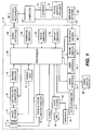
- FIG. 1 depicts a block diagram of a digital photography system, including a digital camera 10 capable of capturing video images in accordance with the present invention.
- the digital camera 10 is a portable battery operated device, small enough to be easily handheld by a user when capturing and reviewing images.
- the digital camera 10 produces digital images that are stored as digital image files using image memory 30.
- the phrase "digital image” or “digital image file”, as used herein, refers to any digital image file, such as a digital still image or a digital video file.
- the digital camera 10 captures both motion video images and still images. In other embodiments, the digital camera 10 is a digital video camera that captures only motion video images.
- the digital camera 10 can also include other functions, including, but not limited to, the functions of a digital music player (e.g. an MP3 player), a mobile telephone, a GPS receiver, or a programmable digital assistant (PDA).
- a digital music player e.g. an MP3 player
- PDA programmable digital assistant
- the digital camera 10 includes a lens 4 having an adjustable aperture and adjustable shutter 6.
- the lens 4 is a zoom lens and is controlled by zoom and focus motor drives 8.
- the lens 4 focuses light from a scene (not shown) onto an image sensor 14, for example, a single-chip color CCD or CMOS image sensor.
- the lens 4 is one type optical system for forming an image of the scene on the image sensor 14. In other embodiments, the optical system may use a fixed focal length lens with either variable or fixed focus.
- the output of the image sensor 14 is converted to digital form by Analog Signal Processor (ASP) and Analog-to-Digital (A/D) converter 16, and temporarily stored in buffer memory 18.
- the image data stored in buffer memory 18 is subsequently manipulated by a processor 20, using embedded software programs (e.g. firmware) stored in firmware memory 28.
- firmware e.g. firmware
- the software program is permanently stored in firmware memory 28 using a read only memory (ROM).
- the firmware memory 28 can be modified by using, for example, Flash EPROM memory.
- an external device can update the software programs stored in firmware memory 28 using the wired interface 38 or the wireless modem 50.
- the firmware memory 28 can also be used to store image sensor calibration data, user setting selections and other data which must be preserved when the camera is turned off.
- the processor 20 includes a program memory (not shown), and the software programs stored in the firmware memory 28 are copied into the program memory before being executed by the processor 20.
- processor 20 can be provided using a single programmable processor or by using multiple programmable processors, including one or more digital signal processor (DSP) devices.
- the processor 20 can be provided by custom circuitry (e.g., by one or more custom integrated circuits (ICs) designed specifically for use in digital cameras), or by a combination of programmable processor(s) and custom circuits.
- ICs custom integrated circuits
- connectors between the processor 20 from some or all of the various components shown in FIG. 1 can be made using a common data bus.
- the connection between the processor 20, the buffer memory 18, the image memory 30, and the firmware memory 28 can be made using a common data bus.
- the image memory 30 can be any form of memory known to those skilled in the art including, but not limited to, a removable Flash memory card, internal Flash memory chips, magnetic memory, or optical memory.
- the image memory 30 can include both internal Flash memory chips and a standard interface to a removable Flash memory card, such as a Secure Digital (SD) card.
- SD Secure Digital
- a different memory card format can be used, such as a micro SD card, Compact Flash (CF) card, MultiMedia Card (MMC), xD card or Memory Stick.
- the image sensor 14 is controlled by a timing generator 12, which produces various clocking signals to select rows and pixels and synchronizes the operation of the ASP and A/D converter 16.
- the image sensor 14 can have, for example, 12.4 megapixels (4088 ⁇ 3040 pixels) in order to provide a still image file of approximately 4000x3000 pixels.
- the image sensor is generally overlaid with a color filter array, which provides an image sensor having an array of pixels that include different colored pixels.
- the different color pixels can be arranged in many different patterns. As one example, the different color pixels can be arranged using the well-known Bayer color filter array, as described in commonly assigned U.S.
- Patent 3,971,065 "Color imaging array” to Bayer, the disclosure of which is incorporated herein by reference.
- the different color pixels can be arranged as described in commonly assigned U.S. Patent Application Publication 2005/191729, filed on July 28, 2007 and titled “Image sensor with improved light sensitivity” to Compton and Hamilton, the disclosure of which is incorporated herein by reference. These examples are not limiting, and many other color patterns may be used.
- the image sensor 14, timing generator 12, and ASP and A/D converter 16 can be separately fabricated integrated circuits, or they can be fabricated as a single integrated circuit as is commonly done with CMOS image sensors. In some embodiments, this single integrated circuit can perform some of the other functions shown in FIG. 1 , including some of the functions provided by processor 20.
- the image sensor 14 is effective when actuated in a first mode by timing generator 12 for providing a motion sequence of lower resolution sensor image data, which is used when capturing video images and also when previewing a still image to be captured, in order to compose the image.
- This preview mode sensor image data can be provided as HD resolution image data, for example, with 1280x720 pixels, or as VGA resolution image data, for example, with 640x480 pixels, or using other resolutions which have significantly fewer columns and rows of data, compared to the resolution of the image sensor.
- the preview mode sensor image data can be provided by combining values of adjacent pixels having the same color, or by eliminating some of the pixel values, or by combining some color pixel values while eliminating other color pixel values.
- the preview mode image data can be processed as described in commonly assigned U.S. Patent 6,292,218 to Parulski, et al. , entitled "Electronic camera for initiating capture of still images while previewing motion images," which is incorporated herein by reference.
- the image sensor 14 is also effective when actuated in a second mode by timing generator 12 for providing high resolution still image data.
- This final mode sensor image data is provided as high resolution output image data, which for scenes having a high illumination level includes all of the pixels of the image sensor, and can be, for example, a 12 megapixel final image data having 4000x3000 pixels.
- the final sensor image data can be provided by "binning" some number of like-colored pixels on the image sensor, in order to increase the signal level and thus the "ISO speed" of the sensor.
- the zoom and focus motor drivers 8 are controlled by control signals supplied by the processor 20, to provide the appropriate focal length setting and to focus the scene onto the image sensor 14.
- the exposure level of the image sensor 14 is controlled by controlling the f/number and exposure time of the adjustable aperture and adjustable shutter 6, the exposure period of the image sensor 14 via the timing generator 12, and the gain (i.e., ISO speed) setting of the ASP and A/D converter 16.
- the processor 20 also controls a flash 2 which can illuminate the scene.
- the lens 4 of the digital camera 10 can be focused in the first mode by using "through-the-lens" autofocus, as described in commonly-assigned U.S. Patent 5,668,597 , entitled “Electronic Camera with Rapid Automatic Focus of an Image upon a Progressive Scan Image Sensor” to Parulski et al., which is incorporated herein by reference.
- This is accomplished by using the zoom and focus motor drivers 8 to adjust the focus position of the lens 4 to a number of positions ranging between a near focus position to an infinity focus position, while the processor 20 determines the closest focus position which provides a peak sharpness value for a central portion of the image captured by the image sensor 14.
- the focus distance which corresponds to the closest focus position can then be utilized for several purposes, such as automatically setting an appropriate scene mode, and can be stored as metadata in the image file, along with other lens and camera settings.
- the processor 20 produces menus and low resolution color images that are temporarily stored in display memory 36 and are displayed on the image display 32.
- the image display 32 is typically an active matrix color liquid crystal display (LCD), although other types of displays, such as organic light emitting diode (OLED) displays, can be used.
- a video interface 44 provides a video output signal from the digital camera 10 to a video display 46, such as a flat panel HDTV display.
- preview mode or video mode
- the digital image data from buffer memory 18 is manipulated by processor 20 to form a series of motion preview images that are displayed, typically as color images, on the image display 32.
- the images displayed on the image display 32 are produced using the image data from the digital image files stored in image memory 30.
- the graphical user interface displayed on the image display 32 is controlled in response to user input provided by user controls 34.
- the user controls 34 are used to select various camera modes, such as video capture mode, still capture mode, and review mode, and to initiate capture of still images and recording of motion images.
- the first mode described above i.e. still preview mode
- the second mode i.e., still image capture mode
- the user controls 34 are also used to turn on the camera, control the lens 4, and initiate the picture taking process.
- User controls 34 typically include some combination of buttons, rocker switches, joysticks, or rotary dials.
- some of the user controls 34 are provided by using a touch screen overlay on the image display 32. In other embodiments, additional status displays or images displays can be used.
- the camera modes that can be selected using the user controls 34 include a "timer" mode.
- a short delay e.g. 10 seconds
- An audio codec 22 connected to the processor 20 receives an audio signal from a microphone 24 and provides an audio signal to a speaker 26. These components can be to record and playback an audio track, along with a video sequence or still image. If the digital camera 10 is a multi-function device such as a combination camera and mobile phone, the microphone 24 and the speaker 26 can be used for telephone conversation.
- the speaker 26 can be used as part of the user interface, for example to provide various audible signals which indicate that a user control has been depressed, or that a particular mode has been selected.
- the microphone 24, the audio codec 22, and the processor 20 can be used to provide voice recognition, so that the user can provide a user input to the processor 20 by using voice commands, rather than user controls 34.
- the speaker 26 can also be used to inform the user of an incoming phone call. This can be done using a standard ring tone stored in firmware memory 28, or by using a custom ring-tone downloaded from a wireless network 58 and stored in the image memory 30.
- a vibration device (not shown) can be used to provide a silent (e.g., non audible) notification of an incoming phone call.
- the digital camera 10 also contains an accelerometer 27 which provides data related to the motion of the camera.
- the accelerometer 27 detects both linear and rotational accelerations for each of three orthogonal directions (for a total of 6 dimensions of input).
- the processor 20 also provides additional processing of the image data from the image sensor 14, in order to produce rendered sRGB image data which is compressed and stored within a "finished" image file, such as a well-known Exif-JPEG image file, in the image memory 30.
- a "finished" image file such as a well-known Exif-JPEG image file
- the digital camera 10 can be connected via the wired interface 38 to an interface/recharger 48, which is connected to a computer 40, which can be a desktop computer or portable computer located in a home or office.
- the wired interface 38 can conform to, for example, the well-known USB 2.0 interface specification.
- the interface/recharger 48 can provide power via the wired interface 38 to a set of rechargeable batteries (not shown) in the digital camera 10.
- the digital camera 10 can include a wireless modem 50, which interfaces over a radio frequency band 52 with the wireless network 58.
- the wireless modem 50 can use various wireless interface protocols, such as the well-known Bluetooth wireless interface or the well-known 802.11 wireless interface.
- the computer 40 can upload images via the Internet 70 to a photo service provider 72, such as the Kodak EasyShare Gallery. Other devices (not shown) can access the images stored by the photo service provider 72.
- the wireless modem 50 communicates over a radio frequency (e.g. wireless) link with a mobile phone network (not shown), such as a 3GSM network, which connects with the Internet 70 in order to upload digital image files from the digital camera 10.
- a radio frequency e.g. wireless
- a mobile phone network not shown
- 3GSM network such as a 3GSM network
- FIG. 2 details a method for using a processor 20 to determine key video frames for a digital video sequence 200 having a time sequence of video frames.
- the digital video sequence 200 is analyzed using an analyze digital video step 210 to determine an importance value 215 as a function of time.
- a form warped time representation step 220 forms a warped time representation 225 for the digital video sequence 200 by temporal relocation of the video frames responsive to the importance value 215 as a function of time.
- a subdivide warped time representation step 230 subdivides the warped time representation 225 into a set of equal time intervals 235.
- a select key video frames step 240 selects a key video frame 245 for each time interval by analyzing the video frames within each time interval 235.
- a store indication of key video frames step 250 stores an indication of the key video frames 245 for the digital video sequence 200 in a processor-accessible memory.
- the analyze digital video step 210 determines an importance value 215 as a function of time.
- An importance value 215 is a quantity that represents the significance of the frames of the digital video sequence 200 as a function of time.
- the importance value 215 is a numerical value that is defined for every frame of the digital video sequence 200. For example, video frames determined to be of high importance, such as video frames containing faces, can be assigned a relatively higher importance value 215. Video frames determined to be of low importance, such as video frames comprising a fast panning motion, can be assigned a relatively lower importance value 215.
- the analyze digital video step 210 includes global motion analysis and local motion analysis.
- Global motion analysis determines global motion information that typically corresponds to motion of the capture device, while local motion analysis determines local motion information that corresponds to the movement of objects within the scene.
- the global motion analysis is performed using a two-parameter global motion model that provides translational offset information (horizontal and vertical translation) as a function of time.
- more complex global motion models can be used to provide additional information such as rotational information on three orthogonal axes and scale (zoom) information.
- Local motion analysis is performed using local motion models that provide dense local motion information.
- the local motion model provides translational motion values for every pixel as a function of time.
- Local motion models can also provide coarser motion estimates, for example providing a translational motion value for every 8x8 or 16 ⁇ 16 block of pixels.
- local motion information provides an indication of the degree of motion occurring in the center region of the video frame. This can be computed, for example, by counting the number of pixels in the center region of a video frame which are identified as being part of moving regions.
- the computation of the global and local motion information is performed after the digital video sequence 200 has been captured, compressed and stored in a processor accessible memory. This requires that the compressed digital video sequence be decompressed before it can be analyzed.
- the global and local motion information are determined during the digital video capture process prior to the digital video sequence 200 being compressed. This mitigates the need to decompress the digital video sequence for purposes of performing the global and local motion analysis.
- the computed global and local motion information can be stored as metadata associated with the digital video sequence 200.
- the metadata can either be stored in the digital video file, or as a separate file associated with the stored digital video sequence. Such a method is described in commonly-assigned co-pending U.S. Patent Application 12/786,483 , entitled "Video summary method and system.
- the analyze digital video step 210 includes the step of classifying a plurality of the video frames.
- FIG. 3 describes the classification process for a preferred embodiment of the present invention.
- Global motion information 310 and local motion information 320 determined by the global motion analysis and the local motion analysis, respectively, are inputs to a classifier 330, which determines video frame classifications 340 for a plurality of the video frames.
- video frame classifications 340 assigned for video frames include: zoom, fast pan, interesting and inactive.
- the classifier 330 classifies a video frame as a zoom video frame whenever the camera is zooming in or zooming out while that frame is being captured.
- Zooming processes can be detected through digital image analysis using global motion models that include a scale parameter to detect zoom.
- Zooming processes can also be detected at capture time by recognizing signals sent to the zoom motor driver 8 to adjust the zoom lens 4.
- the classifier 330 classifies a video frame as a fast pan video frame whenever the magnitude of global translational motion occurring during that video frame exceeds a threshold. Individual video frames corresponding to fast panning motions are generally very blurry and are therefore not good candidates for key video frames to represent a digital video sequence.
- the classifier 330 classifies a video frame as an inactive video frame whenever the magnitude of the global translational motion and the magnitude of the zoom motion, as well as the magnitude of the local motion, are below specified thresholds. Such video frames are indicative of a relatively stationary capture device and a scene with relatively little object motion. A single key video frame is often sufficient to represent an inactive segment of a digital video sequence.
- all remaining video frames can be classified as interesting video frames.
- the interesting video frames represent segments of the digital video sequence most likely to contain good candidates for key video frames to represent the digital video sequence.
- an importance value 215 ( FIG. 2 ) is assigned for each video frame.
- Importance values 215 can be determined from the video frame classifications 340 by associating an appropriate importance value with each of the different video frame classifications 340.
- the table below illustrates example importance values 215 for each of the video frame classifications 340 described above: Table 1: Video frame classification importance values Video Frame Classification Importance Value Zoom 0.3 Fast Pan 0.2 Inactive 0.6 interesting 1.0
- the form warped time representation step 220 forms a warped time representation 225 for the digital video sequence by temporal relocation of the video frames responsive to the importance value 215 as a function of time.
- FIGS. 4 and 5 illustrate this warping process according to one embodiment of the present invention.
- FIG. 4 illustrates a digital video sequence 400 beginning at time unit 0 and ending at time unit 100, divided into equal digital video intervals 410 that are each 5 time units long.
- the absolute value of each time unit is not important for the following discussion, but as an example, each time unit can represent 10 milliseconds, and each 5 time unit long piece of the digital video sequence can represent one video frame. In this case, each video frame is 50 milliseconds, such that the digital video sequence is captured at 20 video frames per second.
- the digital video intervals 410 can include a plurality of video frames rather than a single video frame.
- FIG. 5 represents the warped time representation 225 of this digital video sequence 200, wherein each digital video frame is temporally relocated responsive to the importance values 215 associated with the digital video frames based on their corresponding video frame classes.
- FIG. 5 illustrates a warped time representation 500 comprised of warped digital video intervals 510 for the digital video sequence 400.
- video frame 1 is classified as "interesting”
- video frames 2-8 are classified as “fast pan”
- video frames 9-12 are classified as "interesting”
- video frames 13-16 are classified as "inactive”
- video frames 17-20 are classified as "interesting.”
- a temporal extent of 5.0*0.3 1.5 time units is assigned to the warped digital video interval 510.
- a temporal extent of 5.0*0.2 1.0 time units is assigned to the warped digital video interval 510;
- the warped time representation 500 is formed by assigning shorter temporal extent to digital video intervals 410 in portions of the digital video having lower importance values 215, and assigning longer temporal extent to video frames in portions of the digital video having higher importance values 215.
- the subdivide warped time representation step 230 ( FIG. 2 ) subdivides the warped time representation 225 into a set of equal time intervals 235.
- FIG. 6 illustrates this step for the case in which the warped time representation 500 is subdivided into a set of 5 equal time intervals 520. Note that in the warped time representation, the absolute number of digital video frames (i.e., warped digital video intervals 510) contained in each equal time interval 520 will generally not be constant.
- FIG. 7 illustrates the location of corresponding time intervals 420 relative to the original representation of the digital video sequence 400.
- the first time interval 420 contains more than 40% of the total number of digital video frames contained in the digital video sequence 400, while the second time interval 420 contains fewer than 15%.
- a warped time representation 225 ( FIG. 2 ) has the advantage that it allows the selection of one key video frame from within each time interval in a manner such that the key video frames have breadth throughout the entire digital video sequence, while simultaneously being biased to favor regions of high importance value.
- the number of time intervals 235 can be automatically determined, based on, for example, the overall temporal extent of the warped time representation of the digital video sequence. Alternatively, the number of time intervals can be user-specified.
- the select key video frames step 240 selects a key video frame 245 for each time interval 235 by analyzing the video frames within each time interval 235.
- this analysis includes assigning a selection score to a plurality of video frames within each time interval 235, wherein the selection score is a function of the global motion and the local motion.
- the video frame with the highest selection score within a time interval 235 can be selected as the key video frame 245 for that time interval 235.
- Most methods for compressing digital video sequences involve encoding some video frames as independently-encoded video frames, and other video frames as predictive-encoded video frames.
- only independently-encoded video frames are considered as candidates for key video frames within each time interval 235, and selection scores are only computed for independently-encoded video frames.
- Independently-encoded video frames refer to video frames that are encoded without any reference to other video frames. Such video frames can be decoded without requiring any information from other video frames.
- predictive-encoded video frames are encoded based on a prediction from one or more neighboring video frames. As such, a predictive-encoded video frame can not be decoded independently because it requires knowledge of one or more other video frames.
- independently-encoded video frames are encoded at high quality, specifically because they are used as a prediction for subsequent video frames, and a high quality prediction yields efficient encoding of the subsequent video frames.
- independently-encoded frames are preferable candidates for key video frames 245, both because they are typically of high image quality and also because they can be decoded quickly from the compressed digital video sequence without needing to decode any additional video frames.
- the selection score for a video frame can be a function of several different inputs, including global translational motion, zoom, local motion, and proximity to the previous key video frame.
- video frames with corresponding high global translational motion magnitude are assigned relatively low selection score because high levels of global motion typically produces motion blur in the video frame.
- video frames that follow the conclusion of a zoom sequence are assigned relatively high selection scores based on the assumption that the user has intentionally performed a zoom to focus attention on a particular region of interest. Therefore, video frames shortly after the zoom concludes (allowing some time for the capture device to refocus) are likely to be of high importance and are good candidates to be considered for key video frames 245.
- Video frames with very low levels of object motion are assigned relatively low selection scores based on the assumption that video frames of interest likely contain some object activity.
- Video frames in close temporal proximity to other key video frames 245 are assigned lower selection scores based on the assumption that the captured video has high temporal correlation, and therefore video frames in close temporal proximity are more likely to contain redundant information.
- temporal proximity can be measured with respect to previous key video frames.
- temporal proximity can be measured with respect to both temporally previous and subsequent key video frames.
- S(n) is the selection score
- GM(n) is a global motion term
- LM(n) is a local motion term
- Z(n) is a zoom term
- P(n) is a proximity term
- n is the video frame.
- the individual terms of the selection score can each vary from a value of 0 to a value of 1, depending on the characteristics of the video frame.
- the global motion term (GM) can be computed using any method known in the art.
- the global motion term has a value of 0 for all video frame global motion magnitude values exceeding a threshold, T GM , a value of 1 for a video frame global motion magnitude value of 0, and a value that decreases linearly from 1 to 0 for video frame global motion magnitude values between 0 and T GM :
- GM n ⁇ 1 - x GM n / T GM ; x GM n ⁇ T GM 0 ; x GM n > T GM where x GM (n) is the magnitude of the global motion vector for video frame n.
- the cosine function penalizes global motion more slowly at small magnitudes than a linear function.
- the local motion term can be computed using any method known in the art.
- local motion is measured as a function of a difference value computed between two video frames after accounting for global motion.
- the difference value can be computed by shifting one of the video frames using the global motion vector, computing pixel differences between the overlapping pixels of the sifted video frames, and then computing the average pixel difference to provide a video frame local motion value.
- a greater video frame local motion value is generally suggestive of a greater amount of local motion, although other situations, such as changes in lighting, can also cause large differences between video frames.
- the LM term is biased to preferentially select video frames having moderate levels of local motion.
- a function can be used where the LM term has a value of 1 for a video frame local motion value at the mean value of all video frame local motion value within a temporal interval. As local motion gets smaller, the LM value decreases linearly to a value of 0.9 at a video frame local motion value of 0. As local motion increases, the LM value decreases linearly to a value of 0.8 at the maximum video frame local motion value in the temporal interval.
- LM n ⁇ 0.9 + 0.1 x LM n / x LM ⁇ ; x LM n ⁇ x LM ⁇ 1.0 - 0.2 ⁇ x LM n - x LM ⁇ x LM , max - x LM ⁇ ; x GM ⁇ ⁇ x LM n > x LM , max where x LM (n) is the video frame local motion value for video frame n; x LM is the mean value of all video frame local motion values for the video frames within the temporal interval; and x LM,max is the maximum video frame local motion value for all of the video frames within the temporal interval.
- the local motion term can be determined by computing local motion vectors between corresponding pixels in two video frames after accounting for global motion. The average magnitude of the local motion vectors can then be determined for each video frame and used as the video frame local motion values.
- the zoom term (Z) can be computed using any method known in the art.
- the zoom term has a value of 0 for video frames where a zoom action is in progress or has just completed (and the device has not had enough time to refocus yet), the zoom term has a value of 1 for two seconds immediately following a zoom action (after allowing time for the device to refocus), and the zoom term has a value of 0.5 for all other video frames.
- the proximity term (P) can be computed using any method known in the art.
- the proximity term has a value of 1 whenever a video frame is at least two seconds separated from the previous key video frame, and has a value that linearly decreases to 0 as the distance from the previous key video frame decreases to 0.
- Key video frames 245 can be selected in accordance with the present invention using any other method known in the art to select a key video frame 245 from within a time interval 235.
- the store indication of key video frames step 250 stores an indication of the key video frames 245 in a processor-accessible memory.
- the key video frames 245 can be extracted as individual video frames.
- the individual video frames can then be compressed and stored within individual digital image files, such as well-known Exif-JPEG image files.
- An advantage of storing the key video frames as separate digital image files is that they are immediately accessible by any standard image reader.
- the key video frames can be indicated by storing metadata associated with the digital video sequence 200.
- the metadata can be a list of video frames that have been identified to be key video frames 245.
- a "smart" video reader can interpret the metadata associated with the digital video and thereby extract the key video frames 245.
- the key video frames can be indicated by storing video frame thumbnail images as metadata associated with the digital video.
- the video frame thumbnail images are low resolution versions of the key video frames.
- the method for determining key video frames represents one portion of a process for forming a video summary.
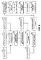
- FIG. 8 illustrates the steps for a method of forming a video summary according to one embodiment of the present invention.
- the analyze digital video step 210, the form warped time representation step 220, the subdivide warped time representation step 230, the select key video frames step 240 and the store indication of key video frames step 250 are performed as described previously with respect to FIG. 2 .
- a determine highest-ranked key video frames step 260 ranks the key video frames 245 according to a specified criterion to determine a set of highest-ranked key video frames 265.
- a form key video snippets step 270 forms key video snippets 275 corresponding to the highest-ranked key video frames 265.
- a form video summary step 280 assembles the key video snippets 275 to form a video summary 285.
- a store video summary representation step 290 stores a representation of the video summary 285 in a processor-accessible memory.
- the store video summary representation step 290 can use any method known in the art, such as those described in commonly assigned, co-pending U.S. Patent Application 12/786,483 , entitled "Video summary method and system".
- One of these methods includes decompressing at least part of the stored digital video to extract video frames corresponding to the video summary, and compressing the extracted video frames to form a compressed video summary, which is then stored in a processor-accessible memory.
- Another of these methods includes generating metadata providing an indication of the video frames in the digital video sequence corresponding to the video summary, and wherein the metadata is stored in association with the stored digital video.
- indications of various transition effects that can be used to transition between the key video snippets can also be stored as metadata associated with the digital video sequence.
- FIG. 9 illustrates additional details for the determine highest-ranked key video frames step 260 according to the one embodiment of the present invention.
- An analyze digital video step 910 analyzes the digital video to determine a camera fixation pattern 915.
- a rank key video frames step 920 determines the highest-ranked key video frames 265 for the digital video responsive to the camera fixation pattern 915.
- the analyze digital video step 910 analyzes the digital video to determine the camera fixation pattern 915.
- the camera fixation pattern 915 represents the region of the image scene being captured as a function of time throughout the video capture process.
- the camera fixation pattern 915 is determined by analyzing the global camera motion. A stationary camera views the same portion of the image scene at all times, and has a camera fixation pattern 915 represented as a single point
- the camera fixation pattern 915 for a moving camera will correspond to a motion trace representing the motion of the camera.
- FIG. 10 illustrates a fixation location histogram 930 representing a camera fixation pattern 915 ( FIG. 9 ) for a digital video sequence 200 that includes some panning motions.
- a motion trace 925 is determined by analyzing the global translational motion of the video capture. The video capture process begins with the motion trace starting at an arbitrary location. For example, the video capture can be defined to begin at the origin (0,0) on a two-dimensional plane. (In the example given in FIG. 10 , the video capture begins at the horizontal axis value of approximately 200, and the vertical axis value of approximately 10.) Global translational motion is then characterized by determining pixel offsets between consecutive video frames. The motion trace 925 is determined by tracing cumulative pixel offsets throughout the entire video capture.
- the motion trace 925 is represented using a histogram of camera fixation locations.
- the histogram bin for a particular camera fixation location is incremented by one for each video frame which is fixated at that camera fixation location.
- the camera fixation histogram 930 in FIG. 10 is a representation of such a histogram of camera fixation locations.
- Higher image intensity values at a particular location are an indication that a greater number of video frames were fixated at a given location. It can be seen that the camera was panned both vertically and horizontally during the capture process, and that there were some intervals where the camera fixation was held relatively constant.
- the camera fixation pattern is spatially quantized into pixel regions.
- the quantization factor used in FIG. 10 was 10 pixels. That is to say that each bin in the histogram (each offset of one unit vertically or horizontally in FIG. 10 ) has a width of 10 pixels. For each global translational motion of 10 pixels in a given direction, the fixation position moves in that direction to the next bin in the histogram.
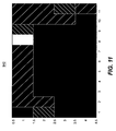
- FIG. 11 illustrates a fixation location histogram 940 corresponding to the same video capture as in FIG. 10 for which a quantization factor of 240 is used. This reduces the total number of histogram bins required to represent the fixation pattern. Additionally, it gives a more concentrated representation of the regions of fixation that will be less effected by camera shake and subtle movements that can change the histogram bin for small quantization factors. From examination of FIG. 11 , it can be seen that there are four main camera fixation regions during the course of the digital video sequence.
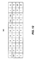
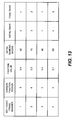
- FIG. 12 is a numerical representation of the fixation location histogram 940 given in FIG. 11 .
- the numerical values indicate the number of video frames corresponding to a given bin in the fixation location histogram 940 throughout the video capture.
- the four main camera fixation regions all have greater than 200 video frames fixated on that region, while the remaining transitory regions all have fewer than 100 video frames each.
- each region of the camera fixation pattern has an associated fixation value that is a function of the number of video frames in that region.
- the histogram value is given as an absolute number of video frames in each region.
- the histogram values can be scaled by a scale factor.
- the histogram values can be normalized by the total number of video frames in the video capture.
- a region of the image scene that the camera fixates on is suggestive of a region of interest in the video capture.
- video frames corresponding to regions of high fixation are good candidates for key video frames.
- the camera fixation pattern is determined by global motion analysis as was described with respect to FIGS. 10-12 .
- the camera fixation pattern can also account for zoom.
- One method for handling zoom is by defining a three-dimensional motion trace, where two axes of the motion trace correspond to global translational motion (horizontal and vertical), and the third axis of the motion trace corresponds to zoom magnification.
- the camera fixation pattern can also account for camera rotation.
- the global motion information is determined by analyzing data from an accelerometer 27 ( FIG. 1 ).
- the accelerometer data can be converted to translational motion in units of pixels.
- the global motion information is determined using digital motion estimation. Those skilled in the art will recognize that there are many well-known methods for computing a global translational motion estimate between a pair of digital images.
- the quantization factor used in determining the camera fixation pattern histogram is a function of the resolution of the video capture.
- the quantization factor is equal to one half of the resolution of a video frame. For a VGA video having 640 columns and 480 rows, this corresponds to a quantization factor of 320 in the horizontal direction and 240 in the vertical direction.
- the motion traces illustrated in FIGS. 10 and 11 contain no temporal information. That is to say, while there is an indication of the overall camera fixation regions throughout the video capture, there is no indication of when in the video capture process they occur.
- the temporal information is retained and the motion trace indicates the camera fixation location as a function of time.
- the key video frames 245 are preferably determined as described previously with respect to FIG. 2 .
- the key video frames 245 can be determined using any method known in the art.
- the rank key video frames step 920 ranks the key video frames 245 responsive to the camera fixation pattern 915.
- a corresponding camera fixation pattern region is determined for each key video frame.
- the camera fixation pattern region for a particular key video frame can be determined based on the location of the global translational motion trace at the capture time of the particular key video frame.
- a corresponding fixation value is then determined from the fixation location histogram for the digital video sequence for each key video frame.
- the key video frames are initially ranked by fixation value.
- the key video frame with the highest fixation value is the highest initially ranked key video frame.
- Additional ranking measures can also be used to rank the key video frames.
- these additional ranking measures operate in conjunction with the fixation value to provide the initial ranking.
- the additional ranking measures are secondary ranking measures, and are used to break ties among all key video frames having equivalent fixation values.
- One example of an additional ranking measure for ranking key video frames is the selection score assigned to each frame as described previously with regards to the select key video frames step 240 in FIG. 2 .
- the ranking of the key video frames is determined iteratively. In a first iteration, the highest ranking key video frame is determined. This can be determined by selecting the key video frame having the highest ranking based on fixation value and additional ranking measures.
- each subsequent iteration involves re-ranking the remaining key video frames, and selecting the highest-ranked remaining key video frame.
- the key video frames are subsequently rank-adjusted by redundancy. Redundancy corresponds to multiple key video frames corresponding to a single fixation region.
- the key video frames are re-ranked at each iteration to favor regions that have not yet been represented in the ranked key video frame list
- FIG. 13 illustrates an example of this ranking and re-ranking process.
- Four key video frames are selected to represent a particular digital video sequence.
- Key video frame 1 corresponds to camera fixation region 3, which has a corresponding fixation value of 0.4.
- Key video frame 1 also has an initial ranking score of 80, based on the fixation value as well as an additional scoring measure.
- key video frame 2 has a corresponding camera fixation region 6, fixation value 0.2, and initial ranking score of 70.
- Key video frame 3 has a corresponding camera fixation region of 3, fixation value of 0.4, and initial ranking score of 90.
- Key video frame 4 has a corresponding camera fixation region of 2, fixation value of 0.1, and initial ranking score of 60.
- the initial ranking of the key video frames is key video frame 3, key video frame 1, key video frame 2, and key video frame 4.
- Key video frame 3 is selected in the first iteration of the final ranking as the highest-ranked key video frame. Subsequently, the remaining key video frames are re-ranked to favor those key video frames from camera fixation regions other than camera fixation region 3. Consequently, key video frame 2 is selected in the second iteration of the final ranking.
- Key video frame 1 is only selected in the ranking process after all other fixation regions are represented, and as a result becomes the final ranked key video frame.
- the form key video snippets step 270 forms key video snippets 275 corresponding to one or more highest-ranked key video frames 265.
- the form key video snippets step 270 forms the key video snippets 275 according to a predefined set of criteria, including a criterion which specifies the total time duration for the video summary and a criterion which specifies the minimum time duration for each of the key video snippets.
- the highest-ranked key video frames 265 act as foundations from which the key video snippets 275, and ultimately the video summary 285, are built.
- the number of highest-ranked key video frames 265 that are selected to form the key video snippets 275 will generally depend on the total time duration of the video summary and the minimum time duration of the key video snippets.
- a key video snippet 275 is centered around each of the selected highest-ranked key video frames 265.
- the start and end time of each key video snippet is responsive to other criteria.
- the digital video sequence can be analyzed to determine an importance value as a function of time, and the start and end times for a key video snippet can be determined responsive to a criterion which encourages the inclusion of video frames having high importance values. Analyzing the digital video to determine an importance value as a function of time can be performed as described with respect to the analyze digital video step 210 of FIG. 2 .
- the importance value can favor, for example, the inclusion of interesting frames rather than inactive or fast pan frames.
- the start and end points of each key video snippet can be adjusted to be responsive to this criterion while simultaneously satisfying constraints on the total duration for the video summary and the minimum duration of each key video snippet.
- the digital video is analyzed to determine a level of audio activity as a function of time.
- the start and end times for a key video snippet 275 can be determined responsive to a criterion which encourages selecting start and end times corresponding to low levels of audio activity. This minimizes the likelihood that a key video snippet either begins or ends with clipped speech. In most cases, it is desirable that the key video snippets contain complete speaking segments, and do not cut off a speaker in the middle of a sentence.
- the key video snippets are formed according to a criterion which discourages the formation of key video snippets that have similar content.
- a criterion which discourages the formation of key video snippets that have similar content.
- One method for discouraging the formation of key video snippets having similar content is by restricting the number of highest-ranked key video frames used to form key video snippets to only those having unique camera fixation regions. In the case that this number is smaller than would otherwise be chosen, the time duration of each individual key video snippet can be lengthened to satisfy the overall video summary time duration criterion.
- key video snippets 275 corresponding to the highest-ranked key video frames 265 that are separated by time intervals less than a specified threshold are merged to form a single key video snippet.
- Merging of key video snippets can prevent the case that the end of one key video snippet overlaps the beginning of the next key video snippet, or are separated by only a short time duration.
- a video summary containing such transitions would tend to be confusing to a viewer.
- a visually preferable video summary contains a single merged key video snippet that eliminates the transition between the two original key video snippets.
- an encoding group of video frames may include one independently-encoded video frame (i.e., an "I” frame) and a plurality of predictive-encoded video frames (i.e., "P" frames), where each "P" frame is predicted from the previous frame.
- a particular encoding group of video frames ends and a new encoding group of video frames begins when the next "I" frame is encountered.
- "I" frames offer access points into the compressed digital video sequence, wherein frames can be extracted starting at an "I" frame.
- entire encoding groups of video frames can be extracted from a compressed digital video sequence and transcoded into a video summary only requiring decoding of header information indicating the location of and number of compressed bytes comprising the encoding group of video frames.
- header information indicating the location of and number of compressed bytes comprising the encoding group of video frames.
- the total time duration for the video summary is automatically determined. It can be determined responsive to the time duration of the original video, or the time duration of the warped time representation of the digital video. In other embodiments of the present invention, the total time duration of the video summary is user-specified. For example, a user may have a specific desired video summary length in mind. The number and duration of the key video snippets 275 can then be determined responsive to the total time duration of the video summary.
- FIG. 14 illustrates an example of the formation of key video snippets according to one embodiment.
- the key video snippets are formed such that they are of equal time duration and are centered around a set of corresponding highest-ranked key video frames.
- a digital video sequence 610 is analyzed and three highest-ranked key video frames 640 are selected.
- a key video snippet 620 is formed corresponding to each highest-ranked key video frame 640.
- Speaking segments 630 are indicated within the digital video sequence 610.
- This process for determine key video snippets 620 has the drawback that the first key video snippet 620 cuts off a speaking segment 630 before it is finished.
- the determined key video snippets 620 also have the drawback that the second and third key video snippets have a short time duration between them.
- FIG. 15 illustrates the formation of key video snippets 620 from the same digital video sequence 610 according to an alternate embodiment.
- the formation of the key video snippets 620 is further responsive to additional criteria.
- the length of all key video snippets 620 are not required to be equal, and the location of each key video snippet 620 is not required to be centered around the corresponding highest-ranked key video frame 640.
- the start and end points of each key video snippet 620 are responsive to a criterion encouraging selection of start and end times corresponding to low levels of audio activity.
- the key video snippets 620 are formed responsive to a criteria that merges key video snippets that have corresponding highest-ranked key video frames 640 that are separated by a time interval less than a specified threshold.
- the first key video snippet 620 is lengthened and shifted off-center relative to the corresponding highest-ranked key video frame 640, so that the key video snippet 620 does not clip the speaking segment 630 at either end.
- the short time duration between the second and third highest-ranked key video frames 640 results in the merging of the corresponding key video snippets into a single key video snippet 620.
- the overall time duration constraint is enforced by adjusting the start and end times as necessary while still merging temporally close key video snippets 620 and avoiding clipped speaking segments 630.
- the key video snippets 620 shown in FIG. 15 generate a more pleasing video summary than the key video snippets 620 in FIG. 14 .
- the form video summary step 280 ( FIG. 8 ) assembles the key video snippets 275 to form the video summary 285.
- the key video snippets are assembled in chronological order corresponding to their order of occurrence in the digital video sequence.
- a computer program product can include one or more storage medium, for example; magnetic storage media such as magnetic disk (such as a floppy disk) or magnetic tape; optical storage media such as optical disk, optical tape, or machine readable bar code; solid-state electronic storage devices such as random access memory (RAM), or read-only memory (ROM); or any other physical device or media employed to store a computer program having instructions for controlling one or more computers to practice the method according to the present invention.
- magnetic storage media such as magnetic disk (such as a floppy disk) or magnetic tape
- optical storage media such as optical disk, optical tape, or machine readable bar code
- solid-state electronic storage devices such as random access memory (RAM), or read-only memory (ROM); or any other physical device or media employed to store a computer program having instructions for controlling one or more computers to practice the method according to the present invention.
Landscapes
- Engineering & Computer Science (AREA)
- Multimedia (AREA)
- Signal Processing (AREA)
- Library & Information Science (AREA)
- Databases & Information Systems (AREA)
- Theoretical Computer Science (AREA)
- General Engineering & Computer Science (AREA)
- General Physics & Mathematics (AREA)
- Physics & Mathematics (AREA)
- Computer Security & Cryptography (AREA)
- Data Mining & Analysis (AREA)
- Studio Devices (AREA)
- Television Signal Processing For Recording (AREA)
- Studio Circuits (AREA)
Claims (17)
- Verfahren zum Bestimmen von Key Video Frames (245) für ein Digital Video (200), das eine Sequenz von Video Frames umfasst, wobei das Verfahren das Verwenden eines Prozessors zum Durchführen der folgenden Schritte umfasst:Analysieren des Digital Videos zum Bestimmen eines Wichtigkeitswerts (215) für jedes Video Frame;Erstellen einer Zeitschleifendarstellung (225) des Digital Videos (200) durch Zuweisen einer zeitlichen Ausdehnung zu jedem Video Frame, die unter Verwendung des Wichtigkeitswerts (215) des Video Frames berechnet wird;Unterteilen der Zeitschleifendarstellung (225) in einen Satz von gleichen Zeitintervallen (235);Auswählen eines Key Video Frames (240) für jedes Zeitintervall (235); undSpeichern einer Anzeige der Key Video Frames (240) in einem für einen Prozessor zugänglichen Speicher.
- Verfahren nach Anspruch 1, wobei das Analysieren des Digital Videos das Analysieren einer globalen Bewegung (310) umfasst.
- Verfahren nach Anspruch 1, wobei das Analysieren des Digital Videos das Analysieren einer lokalen Bewegung (320) umfasst.
- Verfahren nach Anspruch 1, wobei das Analysieren des Digital Videos (200) das Klassifizieren einer Vielzahl von Video Frames in Video Frame-Klassifizierungen (340) auf der Basis von Global-Bewegungs-Informationen und Lokal-Bewegungs-Informationen umfasst.
- Verfahren nach Anspruch 4, wobei die Video Frame-Klassifizierungen eine Bildvergrößerung/-verkleinerung, einen schnellen Schwenk, interessant oder inaktiv umfassen.
- Verfahren nach Anspruch 4, wobei jeder Video Frame-Klassifizierung (340) ein entsprechender Klassifizierungs-Wichtigkeitswert zugewiesen wird.
- Verfahren nach Anspruch 1, wobei das Auswählen eines Key Video Frames (240) für jedes Zeitintervall (235) das Zuweisen eines Auswahlergebnisses zu einer Vielzahl von Video Frames innerhalb jedes Intervalls umfasst.
- Verfahren nach Anspruch 7, wobei das Auswahlergebnis eine Funktion der globalen Bewegung und der lokalen Bewegung ist.
- Verfahren nach Anspruch 1, wobei das Auswählen eines Key Video Frames (240) für jedes Zeitintervall (235) ferner das Auswählen eines unabhängig kodierten Video Frames als das Key Video Frame (240) innerhalb jedes Zeitintervalls (235) umfasst.
- Verfahren nach Anspruch 1, wobei das Speichern einer Anzeige der Key Video Frames (240) das Extrahieren einzelner Key Video Frames (240) als separate Dateien umfasst.
- Verfahren nach Anspruch 1, wobei das Speichern einer Anzeige der Key Video Frames (240) das Speichern einer Liste von Key Video Frames (240) als dem Digital Video zugeordnete Metadaten umfasst.
- Verfahren nach Anspruch 1, wobei das Speichern einer Anzeige der Key Video Frames (240) das Speichern von Miniaturbildern für die Key Video Frames (240) als dem Digital Video zugeordnete Metadaten umfasst.
- Verfahren nach Anspruch 1, wobei das Erstellen der Zeitschleifendarstellung (225) das Zuweisen einer kürzeren zeitlichen Ausdehnung zu Video Frames mit niedrigeren Wichtigkeitswerten (215) umfasst.
- Verfahren nach Anspruch 1, wobei das Erstellen der Zeitschleifendarstellung (225) das Zuweisen einer längeren Zeitausdehnung zu Video Frames mit höheren Wichtigkeitswerten (215) umfasst.
- Verfahren nach Anspruch 1, wobei die Anzahl von Zeitintervallen benutzerspezifiziert ist.
- Verfahren nach Anspruch 1, das ferner umfasst:Einstufen der Key Video Frames (240);Erstellen von Key Video-Ausschnitten (275) entsprechend den am höchsten eingestuften Key Video Frames;Assemblieren der Key Video Frame-Ausschnitte (275) zum Erstellen einer Video-Zusammenfassung (285); undSpeichern einer Darstellung der Video-Zusammenfassung (285) in einem für einen Prozessor zugänglichen Speicher.
- Digital Video-Kamerasystem, das umfasst:einen Bildsensor (14);ein optisches System zum Ausbilden eines Bilds einer Szene auf dem Bildsensor (14);ein Datenverarbeitungssystem; undein Speichersystem, das kommunikativ mit dem Datenverarbeitungssystem verbunden ist und Anweisungen speichert, die dazu vorgesehen sind, zu bewirken, dass das Datenverarbeitungssystem ein Verfahren zum Bestimmen von Key Video Frames für ein Digital Video implementiert, wobei die Anweisungen umfassen:Erfassen eines Digital Videos (200) unter Verwendung des Bildsensors, wobei das Digital Video (200) eine Sequenz von Video Frames umfasst;Analysieren des Digital Videos (200) zum Bestimmen eines Wichtigkeitswerts (215) für jedes Video Frame;Erstellen einer Zeitschleifendarstellung (225) des Digital Videos (200) durch Zuweisen einer zeitlichen Ausdehnung zu jedem Video Frame, die unter Verwendung des Wichtigkeitswerts (215) des Video Frames berechnet wird;Unterteilen der Zeitschleifendarstellung (225) in einen Satz von gleichen Zeitintervallen (235);Auswählen eines Key Video Frames (240) für jedes Zeitintervall (235); undSpeichern einer Anzeige der Key Video Frames (240) in einem für einen Prozessor zugänglichen Speicher.
Applications Claiming Priority (2)
| Application Number | Priority Date | Filing Date | Title |
|---|---|---|---|
| US12/786,471 US8599316B2 (en) | 2010-05-25 | 2010-05-25 | Method for determining key video frames |
| PCT/US2011/036710 WO2011149697A2 (en) | 2010-05-25 | 2011-05-17 | Method for determining key video frames |
Publications (2)
| Publication Number | Publication Date |
|---|---|
| EP2577663A2 EP2577663A2 (de) | 2013-04-10 |
| EP2577663B1 true EP2577663B1 (de) | 2014-10-15 |
Family
ID=44121277
Family Applications (1)
| Application Number | Title | Priority Date | Filing Date |
|---|---|---|---|
| EP11722962.5A Not-in-force EP2577663B1 (de) | 2010-05-25 | 2011-05-17 | Methode zur bestimmung von key-video frames |
Country Status (5)
| Country | Link |
|---|---|
| US (1) | US8599316B2 (de) |
| EP (1) | EP2577663B1 (de) |
| JP (1) | JP5781156B2 (de) |
| CN (1) | CN102939630B (de) |
| WO (1) | WO2011149697A2 (de) |
Families Citing this family (46)
| Publication number | Priority date | Publication date | Assignee | Title |
|---|---|---|---|---|
| US9171578B2 (en) * | 2010-08-06 | 2015-10-27 | Futurewei Technologies, Inc. | Video skimming methods and systems |
| US8665345B2 (en) | 2011-05-18 | 2014-03-04 | Intellectual Ventures Fund 83 Llc | Video summary including a feature of interest |
| US8643746B2 (en) | 2011-05-18 | 2014-02-04 | Intellectual Ventures Fund 83 Llc | Video summary including a particular person |
| US9298312B2 (en) | 2011-06-30 | 2016-03-29 | Intel Corporation | Automated perceptual quality assessment of touchscreen devices |
| US8823794B2 (en) | 2011-06-30 | 2014-09-02 | Intel Corporation | Measuring device user experience through display outputs |
| JP5804817B2 (ja) * | 2011-07-23 | 2015-11-04 | キヤノン株式会社 | 画像処理装置、画像処理方法、およびプログラム |
| US20130089301A1 (en) * | 2011-10-06 | 2013-04-11 | Chi-cheng Ju | Method and apparatus for processing video frames image with image registration information involved therein |
| DE112012005875T5 (de) * | 2012-02-15 | 2014-10-30 | Intel Corporation | Automatische, fortwährende Qualitätsbeurteilung von Touchscreen-Geräten |
| US9076043B2 (en) | 2012-08-03 | 2015-07-07 | Kodak Alaris Inc. | Video summarization using group sparsity analysis |
| US8913835B2 (en) | 2012-08-03 | 2014-12-16 | Kodak Alaris Inc. | Identifying key frames using group sparsity analysis |
| US8989503B2 (en) | 2012-08-03 | 2015-03-24 | Kodak Alaris Inc. | Identifying scene boundaries using group sparsity analysis |
| US9355613B2 (en) * | 2012-10-09 | 2016-05-31 | Mediatek Inc. | Data processing apparatus for transmitting/receiving compression-related indication information via display interface and related data processing method |
| US9568985B2 (en) | 2012-11-23 | 2017-02-14 | Mediatek Inc. | Data processing apparatus with adaptive compression algorithm selection based on visibility of compression artifacts for data communication over camera interface and related data processing method |
| CN104185089B (zh) * | 2013-05-23 | 2018-02-16 | 三星电子(中国)研发中心 | 视频概要生成方法及服务器、客户端 |
| US10121187B1 (en) * | 2014-06-12 | 2018-11-06 | Amazon Technologies, Inc. | Generate a video of an item |
| US10664687B2 (en) * | 2014-06-12 | 2020-05-26 | Microsoft Technology Licensing, Llc | Rule-based video importance analysis |
| US9646227B2 (en) | 2014-07-29 | 2017-05-09 | Microsoft Technology Licensing, Llc | Computerized machine learning of interesting video sections |
| US9934423B2 (en) * | 2014-07-29 | 2018-04-03 | Microsoft Technology Licensing, Llc | Computerized prominent character recognition in videos |
| US20160127807A1 (en) * | 2014-10-29 | 2016-05-05 | EchoStar Technologies, L.L.C. | Dynamically determined audiovisual content guidebook |
| US10089532B2 (en) | 2015-02-23 | 2018-10-02 | Kodak Alaris Inc. | Method for output creation based on video content characteristics |
| CN104750447B (zh) * | 2015-03-16 | 2018-11-13 | 联想(北京)有限公司 | 一种信息处理方法和电子设备 |
| CN106162322A (zh) * | 2015-03-26 | 2016-11-23 | 无锡天脉聚源传媒科技有限公司 | 一种视频处理方法及装置 |
| US10528208B2 (en) | 2015-05-31 | 2020-01-07 | International Busines Machines Corporation | Instantaneous preview of a data stream with non-linear time warping |
| US10595086B2 (en) | 2015-06-10 | 2020-03-17 | International Business Machines Corporation | Selection and display of differentiating key frames for similar videos |
| US10229324B2 (en) * | 2015-12-24 | 2019-03-12 | Intel Corporation | Video summarization using semantic information |
| US10032481B2 (en) * | 2016-03-22 | 2018-07-24 | Verizon Digital Media Services Inc. | Speedy clipping |
| CN105933773A (zh) * | 2016-05-12 | 2016-09-07 | 青岛海信传媒网络技术有限公司 | 视频编辑方法及系统 |
| CN105893631B (zh) * | 2016-05-31 | 2020-10-16 | 努比亚技术有限公司 | 一种视频缩略图的获取方法、装置及终端 |
| CN106060539B (zh) * | 2016-06-16 | 2019-04-09 | 深圳风景网络科技有限公司 | 一种低传输带宽的视频编码方法 |
| WO2018022853A1 (en) * | 2016-07-28 | 2018-02-01 | Kodak Alaris Inc. | A method for dynamic creation of collages from mobile video |
| CN106713943A (zh) * | 2016-12-28 | 2017-05-24 | 深圳Tcl新技术有限公司 | 推送加密节目的方法及装置 |
| US10671852B1 (en) * | 2017-03-01 | 2020-06-02 | Matroid, Inc. | Machine learning in video classification |
| EP3646322A1 (de) * | 2017-06-29 | 2020-05-06 | Dolby International AB | Verfahren, systeme, vorrichtungen und computerprogrammprodukte zur anpassung von externem inhalt an einen video-stream |
| CN107194616A (zh) * | 2017-06-29 | 2017-09-22 | 惠国征信服务股份有限公司 | 企业产能统计系统和方法 |
| CN107835381B (zh) * | 2017-10-17 | 2019-11-19 | 浙江大华技术股份有限公司 | 一种生成动检录像预览图的方法及装置 |
| US10777228B1 (en) * | 2018-03-22 | 2020-09-15 | Gopro, Inc. | Systems and methods for creating video edits |
| CN110166829A (zh) | 2019-05-15 | 2019-08-23 | 上海商汤智能科技有限公司 | 视频处理方法及装置、电子设备和存储介质 |
| US11036435B2 (en) | 2019-08-30 | 2021-06-15 | Western Digital Technologies, Inc. | Search time optimization in solid-state devices |
| CN113453067B (zh) * | 2020-03-27 | 2023-11-14 | 富士通株式会社 | 视频处理装置、视频处理方法和机器可读存储介质 |
| CN112199552B (zh) * | 2020-10-12 | 2024-03-19 | 北京达佳互联信息技术有限公司 | 视频图像的展示方法及装置、电子设备、存储介质 |
| US11849244B2 (en) * | 2021-07-22 | 2023-12-19 | Grass Valley Canada | System and method for temporal keying in a camera |
| US11917206B2 (en) | 2021-12-17 | 2024-02-27 | Lenovo (Singapore) Pte. Ltd. | Video codec aware radio access network configuration and unequal error protection coding |
| US11824653B2 (en) | 2021-12-17 | 2023-11-21 | Lenovo (Singapore) Pte. Ltd. | Radio access network configuration for video approximate semantic communications |
| KR20230129724A (ko) * | 2022-02-03 | 2023-09-11 | 인하대학교 산학협력단 | 효율적인 키프레임 선택 보상 함수를 갖춘 비지도 비디오 요약 방법 및 장치 |
| CN115334307B (zh) * | 2022-10-11 | 2023-02-10 | 浙江大华技术股份有限公司 | 一种数据传输方法、前端设备、视频采集系统和介质 |
| CN115935000B (zh) * | 2023-02-24 | 2023-06-30 | 广东瑞恩科技有限公司 | 一种物联网数据智能存储方法及系统 |
Family Cites Families (48)
| Publication number | Priority date | Publication date | Assignee | Title |
|---|---|---|---|---|
| US3971065A (en) | 1975-03-05 | 1976-07-20 | Eastman Kodak Company | Color imaging array |
| US4642678A (en) | 1984-09-10 | 1987-02-10 | Eastman Kodak Company | Signal processing method and apparatus for producing interpolated chrominance values in a sampled color image signal |
| US4774574A (en) | 1987-06-02 | 1988-09-27 | Eastman Kodak Company | Adaptive block transform image coding method and apparatus |
| US5189511A (en) | 1990-03-19 | 1993-02-23 | Eastman Kodak Company | Method and apparatus for improving the color rendition of hardcopy images from electronic cameras |
| AU4662493A (en) * | 1992-07-01 | 1994-01-31 | Avid Technology, Inc. | Electronic film editing system using both film and videotape format |
| US5493335A (en) | 1993-06-30 | 1996-02-20 | Eastman Kodak Company | Single sensor color camera with user selectable image record size |
| US5828406A (en) | 1994-12-30 | 1998-10-27 | Eastman Kodak Company | Electronic camera having a processor for mapping image pixel signals into color display pixels |
| US5668597A (en) | 1994-12-30 | 1997-09-16 | Eastman Kodak Company | Electronic camera with rapid automatic focus of an image upon a progressive scan image sensor |
| JP3472659B2 (ja) | 1995-02-20 | 2003-12-02 | 株式会社日立製作所 | 映像供給方法および映像供給システム |
| US5652621A (en) | 1996-02-23 | 1997-07-29 | Eastman Kodak Company | Adaptive color plane interpolation in single sensor color electronic camera |
| US5956026A (en) | 1997-12-19 | 1999-09-21 | Sharp Laboratories Of America, Inc. | Method for hierarchical summarization and browsing of digital video |
| US6192162B1 (en) | 1998-08-17 | 2001-02-20 | Eastman Kodak Company | Edge enhancing colored digital images |
| US6833865B1 (en) | 1998-09-01 | 2004-12-21 | Virage, Inc. | Embedded metadata engines in digital capture devices |
| US6625325B2 (en) | 1998-12-16 | 2003-09-23 | Eastman Kodak Company | Noise cleaning and interpolating sparsely populated color digital image using a variable noise cleaning kernel |
| US6462754B1 (en) | 1999-02-22 | 2002-10-08 | Siemens Corporate Research, Inc. | Method and apparatus for authoring and linking video documents |
| US6535639B1 (en) * | 1999-03-12 | 2003-03-18 | Fuji Xerox Co., Ltd. | Automatic video summarization using a measure of shot importance and a frame-packing method |
| US6462742B1 (en) * | 1999-08-05 | 2002-10-08 | Microsoft Corporation | System and method for multi-dimensional motion interpolation using verbs and adverbs |
| WO2001041451A1 (en) | 1999-11-29 | 2001-06-07 | Sony Corporation | Video/audio signal processing method and video/audio signal processing apparatus |
| AUPQ535200A0 (en) | 2000-01-31 | 2000-02-17 | Canon Kabushiki Kaisha | Extracting key frames from a video sequence |
| US7055168B1 (en) | 2000-05-03 | 2006-05-30 | Sharp Laboratories Of America, Inc. | Method for interpreting and executing user preferences of audiovisual information |
| GB0029880D0 (en) | 2000-12-07 | 2001-01-24 | Sony Uk Ltd | Video and audio information processing |
| US7110458B2 (en) * | 2001-04-27 | 2006-09-19 | Mitsubishi Electric Research Laboratories, Inc. | Method for summarizing a video using motion descriptors |
| US7035435B2 (en) * | 2002-05-07 | 2006-04-25 | Hewlett-Packard Development Company, L.P. | Scalable video summarization and navigation system and method |
| US20040052505A1 (en) | 2002-05-28 | 2004-03-18 | Yesvideo, Inc. | Summarization of a visual recording |
| US20040088723A1 (en) * | 2002-11-01 | 2004-05-06 | Yu-Fei Ma | Systems and methods for generating a video summary |
| CA2443365C (en) | 2002-11-19 | 2010-01-12 | F. Hoffmann-La Roche Ag | Methods for the recombinant production of antifusogenic peptides |
| US7224746B2 (en) | 2002-12-31 | 2007-05-29 | Teradyne, Inc | Pre-compensation for digital bit streams |
| US7483618B1 (en) | 2003-12-04 | 2009-01-27 | Yesvideo, Inc. | Automatic editing of a visual recording to eliminate content of unacceptably low quality and/or very little or no interest |
| JPWO2005086478A1 (ja) * | 2004-03-04 | 2008-01-24 | セイコーエプソン株式会社 | 動画像データ処理 |
| JP4259421B2 (ja) * | 2004-08-02 | 2009-04-30 | 日本電信電話株式会社 | 映像の代表画像選出方法及びプログラム |
| US7852370B2 (en) | 2004-11-05 | 2010-12-14 | Yissum Research Development Company Of The Hebrew University Of Jerusalem | Method and system for spatio-temporal video warping |
| US20060110128A1 (en) * | 2004-11-24 | 2006-05-25 | Dunton Randy R | Image-keyed index for video program stored in personal video recorder |
| JP4368819B2 (ja) * | 2005-03-30 | 2009-11-18 | 株式会社日立製作所 | 要約再生装置及び要約再生装置の制御方法 |
| JP4849818B2 (ja) | 2005-04-14 | 2012-01-11 | イーストマン コダック カンパニー | ホワイトバランス調整装置及び色識別装置 |
| EP1883241B1 (de) * | 2005-05-18 | 2016-01-13 | NEC Corporation | Inhaltsanzeigesystem und inhaltsanzeigeverfahren |
| US20100005485A1 (en) | 2005-12-19 | 2010-01-07 | Agency For Science, Technology And Research | Annotation of video footage and personalised video generation |
| US8031775B2 (en) | 2006-02-03 | 2011-10-04 | Eastman Kodak Company | Analyzing camera captured video for key frames |
| US7889794B2 (en) | 2006-02-03 | 2011-02-15 | Eastman Kodak Company | Extracting key frame candidates from video clip |
| US20070226624A1 (en) | 2006-02-23 | 2007-09-27 | Peker Kadir A | Content-based video summarization using spectral clustering |
| US20070237225A1 (en) | 2006-03-30 | 2007-10-11 | Eastman Kodak Company | Method for enabling preview of video files |
| CN101427250B (zh) | 2006-04-20 | 2012-07-04 | Nxp股份有限公司 | 对数据流创建摘要的数据摘要系统和方法 |
| JP5022370B2 (ja) * | 2006-09-12 | 2012-09-12 | パナソニック株式会社 | コンテンツ撮影装置 |
| CA2676632C (en) | 2007-02-01 | 2017-11-07 | Yissum Research Development Company Of The Hebrew University Of Jerusalem | Method and system for video indexing and video synopsis |
| US8503523B2 (en) | 2007-06-29 | 2013-08-06 | Microsoft Corporation | Forming a representation of a video item and use thereof |
| JP4620150B2 (ja) | 2008-10-23 | 2011-01-26 | 株式会社東芝 | 電子機器および映像処理方法 |
| US8195038B2 (en) * | 2008-10-24 | 2012-06-05 | At&T Intellectual Property I, L.P. | Brief and high-interest video summary generation |
| US8274592B2 (en) * | 2009-12-22 | 2012-09-25 | Eastman Kodak Company | Variable rate browsing of an image collection |
| US8446490B2 (en) | 2010-05-25 | 2013-05-21 | Intellectual Ventures Fund 83 Llc | Video capture system producing a video summary |
-
2010
- 2010-05-25 US US12/786,471 patent/US8599316B2/en not_active Expired - Fee Related
-
2011
- 2011-05-17 WO PCT/US2011/036710 patent/WO2011149697A2/en active Application Filing
- 2011-05-17 CN CN201180025386.6A patent/CN102939630B/zh not_active Expired - Fee Related
- 2011-05-17 JP JP2013512653A patent/JP5781156B2/ja not_active Expired - Fee Related
- 2011-05-17 EP EP11722962.5A patent/EP2577663B1/de not_active Not-in-force
Also Published As
| Publication number | Publication date |
|---|---|
| JP5781156B2 (ja) | 2015-09-16 |
| WO2011149697A3 (en) | 2012-01-19 |
| CN102939630B (zh) | 2015-06-17 |
| US8599316B2 (en) | 2013-12-03 |
| US20110292288A1 (en) | 2011-12-01 |
| WO2011149697A2 (en) | 2011-12-01 |
| JP2013533668A (ja) | 2013-08-22 |
| CN102939630A (zh) | 2013-02-20 |
| EP2577663A2 (de) | 2013-04-10 |
Similar Documents
| Publication | Publication Date | Title |
|---|---|---|
| EP2577663B1 (de) | Methode zur bestimmung von key-video frames | |
| US8605221B2 (en) | Determining key video snippets using selection criteria to form a video summary | |
| EP2710594B1 (de) | Videozusammenfassung mit einer bestimmten eigenschaft | |
| US8619150B2 (en) | Ranking key video frames using camera fixation | |
| US9013604B2 (en) | Video summary including a particular person | |
| CN102906818B (zh) | 存储视频摘要的方法和显示相应于视频摘要的视频帧的系统 | |
| US8432965B2 (en) | Efficient method for assembling key video snippets to form a video summary | |
| US8446490B2 (en) | Video capture system producing a video summary |
Legal Events
| Date | Code | Title | Description |
|---|---|---|---|
| PUAI | Public reference made under article 153(3) epc to a published international application that has entered the european phase |
Free format text: ORIGINAL CODE: 0009012 |
|
| 17P | Request for examination filed |
Effective date: 20121204 |
|
| AK | Designated contracting states |
Kind code of ref document: A2 Designated state(s): AL AT BE BG CH CY CZ DE DK EE ES FI FR GB GR HR HU IE IS IT LI LT LU LV MC MK MT NL NO PL PT RO RS SE SI SK SM TR |
|
| RAP1 | Party data changed (applicant data changed or rights of an application transferred) |
Owner name: INTELLECTUAL VENTURES FUND 83 LLC |
|
| DAX | Request for extension of the european patent (deleted) | ||
| 17Q | First examination report despatched |
Effective date: 20131129 |
|
| REG | Reference to a national code |
Ref country code: DE Ref legal event code: R079 Ref document number: 602011010626 Country of ref document: DE Free format text: PREVIOUS MAIN CLASS: G11B0027100000 Ipc: G11B0027280000 |
|
| RIC1 | Information provided on ipc code assigned before grant |
Ipc: G11B 27/28 20060101AFI20140320BHEP Ipc: H04N 21/44 20110101ALI20140320BHEP Ipc: H04N 5/275 20060101ALI20140320BHEP Ipc: G06F 17/30 20060101ALI20140320BHEP |
|
| GRAP | Despatch of communication of intention to grant a patent |
Free format text: ORIGINAL CODE: EPIDOSNIGR1 |
|
| INTG | Intention to grant announced |
Effective date: 20140502 |
|
| GRAS | Grant fee paid |
Free format text: ORIGINAL CODE: EPIDOSNIGR3 |
|
| GRAA | (expected) grant |
Free format text: ORIGINAL CODE: 0009210 |
|
| AK | Designated contracting states |
Kind code of ref document: B1 Designated state(s): AL AT BE BG CH CY CZ DE DK EE ES FI FR GB GR HR HU IE IS IT LI LT LU LV MC MK MT NL NO PL PT RO RS SE SI SK SM TR |
|
| REG | Reference to a national code |
Ref country code: GB Ref legal event code: FG4D Ref country code: CH Ref legal event code: EP |
|
| REG | Reference to a national code |
Ref country code: IE Ref legal event code: FG4D |
|
| REG | Reference to a national code |
Ref country code: AT Ref legal event code: REF Ref document number: 691979 Country of ref document: AT Kind code of ref document: T Effective date: 20141115 |
|
| REG | Reference to a national code |
Ref country code: DE Ref legal event code: R096 Ref document number: 602011010626 Country of ref document: DE Effective date: 20141127 |
|
| REG | Reference to a national code |
Ref country code: NL Ref legal event code: VDEP Effective date: 20141015 |
|
| REG | Reference to a national code |
Ref country code: AT Ref legal event code: MK05 Ref document number: 691979 Country of ref document: AT Kind code of ref document: T Effective date: 20141015 |
|
| REG | Reference to a national code |
Ref country code: LT Ref legal event code: MG4D |
|
| PG25 | Lapsed in a contracting state [announced via postgrant information from national office to epo] |
Ref country code: NL Free format text: LAPSE BECAUSE OF FAILURE TO SUBMIT A TRANSLATION OF THE DESCRIPTION OR TO PAY THE FEE WITHIN THE PRESCRIBED TIME-LIMIT Effective date: 20141015 |
|
| PG25 | Lapsed in a contracting state [announced via postgrant information from national office to epo] |
Ref country code: FI Free format text: LAPSE BECAUSE OF FAILURE TO SUBMIT A TRANSLATION OF THE DESCRIPTION OR TO PAY THE FEE WITHIN THE PRESCRIBED TIME-LIMIT Effective date: 20141015 Ref country code: IS Free format text: LAPSE BECAUSE OF FAILURE TO SUBMIT A TRANSLATION OF THE DESCRIPTION OR TO PAY THE FEE WITHIN THE PRESCRIBED TIME-LIMIT Effective date: 20150215 Ref country code: NO Free format text: LAPSE BECAUSE OF FAILURE TO SUBMIT A TRANSLATION OF THE DESCRIPTION OR TO PAY THE FEE WITHIN THE PRESCRIBED TIME-LIMIT Effective date: 20150115 Ref country code: PT Free format text: LAPSE BECAUSE OF FAILURE TO SUBMIT A TRANSLATION OF THE DESCRIPTION OR TO PAY THE FEE WITHIN THE PRESCRIBED TIME-LIMIT Effective date: 20150216 Ref country code: LT Free format text: LAPSE BECAUSE OF FAILURE TO SUBMIT A TRANSLATION OF THE DESCRIPTION OR TO PAY THE FEE WITHIN THE PRESCRIBED TIME-LIMIT Effective date: 20141015 Ref country code: ES Free format text: LAPSE BECAUSE OF FAILURE TO SUBMIT A TRANSLATION OF THE DESCRIPTION OR TO PAY THE FEE WITHIN THE PRESCRIBED TIME-LIMIT Effective date: 20141015 |
|
| PG25 | Lapsed in a contracting state [announced via postgrant information from national office to epo] |
Ref country code: LV Free format text: LAPSE BECAUSE OF FAILURE TO SUBMIT A TRANSLATION OF THE DESCRIPTION OR TO PAY THE FEE WITHIN THE PRESCRIBED TIME-LIMIT Effective date: 20141015 Ref country code: PL Free format text: LAPSE BECAUSE OF FAILURE TO SUBMIT A TRANSLATION OF THE DESCRIPTION OR TO PAY THE FEE WITHIN THE PRESCRIBED TIME-LIMIT Effective date: 20141015 Ref country code: SE Free format text: LAPSE BECAUSE OF FAILURE TO SUBMIT A TRANSLATION OF THE DESCRIPTION OR TO PAY THE FEE WITHIN THE PRESCRIBED TIME-LIMIT Effective date: 20141015 Ref country code: GR Free format text: LAPSE BECAUSE OF FAILURE TO SUBMIT A TRANSLATION OF THE DESCRIPTION OR TO PAY THE FEE WITHIN THE PRESCRIBED TIME-LIMIT Effective date: 20150116 Ref country code: CY Free format text: LAPSE BECAUSE OF FAILURE TO SUBMIT A TRANSLATION OF THE DESCRIPTION OR TO PAY THE FEE WITHIN THE PRESCRIBED TIME-LIMIT Effective date: 20141015 Ref country code: HR Free format text: LAPSE BECAUSE OF FAILURE TO SUBMIT A TRANSLATION OF THE DESCRIPTION OR TO PAY THE FEE WITHIN THE PRESCRIBED TIME-LIMIT Effective date: 20141015 Ref country code: AT Free format text: LAPSE BECAUSE OF FAILURE TO SUBMIT A TRANSLATION OF THE DESCRIPTION OR TO PAY THE FEE WITHIN THE PRESCRIBED TIME-LIMIT Effective date: 20141015 Ref country code: RS Free format text: LAPSE BECAUSE OF FAILURE TO SUBMIT A TRANSLATION OF THE DESCRIPTION OR TO PAY THE FEE WITHIN THE PRESCRIBED TIME-LIMIT Effective date: 20141015 |
|
| REG | Reference to a national code |
Ref country code: DE Ref legal event code: R097 Ref document number: 602011010626 Country of ref document: DE |
|
| PG25 | Lapsed in a contracting state [announced via postgrant information from national office to epo] |
Ref country code: EE Free format text: LAPSE BECAUSE OF FAILURE TO SUBMIT A TRANSLATION OF THE DESCRIPTION OR TO PAY THE FEE WITHIN THE PRESCRIBED TIME-LIMIT Effective date: 20141015 Ref country code: SK Free format text: LAPSE BECAUSE OF FAILURE TO SUBMIT A TRANSLATION OF THE DESCRIPTION OR TO PAY THE FEE WITHIN THE PRESCRIBED TIME-LIMIT Effective date: 20141015 Ref country code: RO Free format text: LAPSE BECAUSE OF FAILURE TO SUBMIT A TRANSLATION OF THE DESCRIPTION OR TO PAY THE FEE WITHIN THE PRESCRIBED TIME-LIMIT Effective date: 20141015 Ref country code: DK Free format text: LAPSE BECAUSE OF FAILURE TO SUBMIT A TRANSLATION OF THE DESCRIPTION OR TO PAY THE FEE WITHIN THE PRESCRIBED TIME-LIMIT Effective date: 20141015 Ref country code: CZ Free format text: LAPSE BECAUSE OF FAILURE TO SUBMIT A TRANSLATION OF THE DESCRIPTION OR TO PAY THE FEE WITHIN THE PRESCRIBED TIME-LIMIT Effective date: 20141015 |
|
| PLBE | No opposition filed within time limit |
Free format text: ORIGINAL CODE: 0009261 |
|
| STAA | Information on the status of an ep patent application or granted ep patent |
Free format text: STATUS: NO OPPOSITION FILED WITHIN TIME LIMIT |
|
| PG25 | Lapsed in a contracting state [announced via postgrant information from national office to epo] |
Ref country code: IT Free format text: LAPSE BECAUSE OF FAILURE TO SUBMIT A TRANSLATION OF THE DESCRIPTION OR TO PAY THE FEE WITHIN THE PRESCRIBED TIME-LIMIT Effective date: 20141015 |
|
| 26N | No opposition filed |
Effective date: 20150716 |
|
| REG | Reference to a national code |
Ref country code: CH Ref legal event code: PL |
|
| PG25 | Lapsed in a contracting state [announced via postgrant information from national office to epo] |
Ref country code: CH Free format text: LAPSE BECAUSE OF NON-PAYMENT OF DUE FEES Effective date: 20150531 Ref country code: LU Free format text: LAPSE BECAUSE OF FAILURE TO SUBMIT A TRANSLATION OF THE DESCRIPTION OR TO PAY THE FEE WITHIN THE PRESCRIBED TIME-LIMIT Effective date: 20150517 Ref country code: LI Free format text: LAPSE BECAUSE OF NON-PAYMENT OF DUE FEES Effective date: 20150531 Ref country code: MC Free format text: LAPSE BECAUSE OF FAILURE TO SUBMIT A TRANSLATION OF THE DESCRIPTION OR TO PAY THE FEE WITHIN THE PRESCRIBED TIME-LIMIT Effective date: 20141015 |
|
| REG | Reference to a national code |
Ref country code: IE Ref legal event code: MM4A |
|
| PG25 | Lapsed in a contracting state [announced via postgrant information from national office to epo] |
Ref country code: SI Free format text: LAPSE BECAUSE OF FAILURE TO SUBMIT A TRANSLATION OF THE DESCRIPTION OR TO PAY THE FEE WITHIN THE PRESCRIBED TIME-LIMIT Effective date: 20141015 |
|
| REG | Reference to a national code |
Ref country code: FR Ref legal event code: PLFP Year of fee payment: 6 |
|
| PG25 | Lapsed in a contracting state [announced via postgrant information from national office to epo] |
Ref country code: IE Free format text: LAPSE BECAUSE OF NON-PAYMENT OF DUE FEES Effective date: 20150517 |
|
| PG25 | Lapsed in a contracting state [announced via postgrant information from national office to epo] |
Ref country code: MT Free format text: LAPSE BECAUSE OF FAILURE TO SUBMIT A TRANSLATION OF THE DESCRIPTION OR TO PAY THE FEE WITHIN THE PRESCRIBED TIME-LIMIT Effective date: 20141015 |
|
| PG25 | Lapsed in a contracting state [announced via postgrant information from national office to epo] |
Ref country code: SM Free format text: LAPSE BECAUSE OF FAILURE TO SUBMIT A TRANSLATION OF THE DESCRIPTION OR TO PAY THE FEE WITHIN THE PRESCRIBED TIME-LIMIT Effective date: 20141015 Ref country code: HU Free format text: LAPSE BECAUSE OF FAILURE TO SUBMIT A TRANSLATION OF THE DESCRIPTION OR TO PAY THE FEE WITHIN THE PRESCRIBED TIME-LIMIT; INVALID AB INITIO Effective date: 20110517 Ref country code: BG Free format text: LAPSE BECAUSE OF FAILURE TO SUBMIT A TRANSLATION OF THE DESCRIPTION OR TO PAY THE FEE WITHIN THE PRESCRIBED TIME-LIMIT Effective date: 20141015 |
|
| REG | Reference to a national code |
Ref country code: FR Ref legal event code: PLFP Year of fee payment: 7 |
|
| PG25 | Lapsed in a contracting state [announced via postgrant information from national office to epo] |
Ref country code: TR Free format text: LAPSE BECAUSE OF FAILURE TO SUBMIT A TRANSLATION OF THE DESCRIPTION OR TO PAY THE FEE WITHIN THE PRESCRIBED TIME-LIMIT Effective date: 20141015 |
|
| PG25 | Lapsed in a contracting state [announced via postgrant information from national office to epo] |
Ref country code: BE Free format text: LAPSE BECAUSE OF FAILURE TO SUBMIT A TRANSLATION OF THE DESCRIPTION OR TO PAY THE FEE WITHIN THE PRESCRIBED TIME-LIMIT Effective date: 20141015 |
|
| REG | Reference to a national code |
Ref country code: FR Ref legal event code: PLFP Year of fee payment: 8 |
|
| PG25 | Lapsed in a contracting state [announced via postgrant information from national office to epo] |
Ref country code: MK Free format text: LAPSE BECAUSE OF FAILURE TO SUBMIT A TRANSLATION OF THE DESCRIPTION OR TO PAY THE FEE WITHIN THE PRESCRIBED TIME-LIMIT Effective date: 20141015 |
|
| PGFP | Annual fee paid to national office [announced via postgrant information from national office to epo] |
Ref country code: DE Payment date: 20180529 Year of fee payment: 8 |
|
| PGFP | Annual fee paid to national office [announced via postgrant information from national office to epo] |
Ref country code: FR Payment date: 20180525 Year of fee payment: 8 |
|
| PG25 | Lapsed in a contracting state [announced via postgrant information from national office to epo] |
Ref country code: AL Free format text: LAPSE BECAUSE OF FAILURE TO SUBMIT A TRANSLATION OF THE DESCRIPTION OR TO PAY THE FEE WITHIN THE PRESCRIBED TIME-LIMIT Effective date: 20141015 |
|
| PGFP | Annual fee paid to national office [announced via postgrant information from national office to epo] |
Ref country code: GB Payment date: 20180529 Year of fee payment: 8 |
|
| REG | Reference to a national code |
Ref country code: DE Ref legal event code: R119 Ref document number: 602011010626 Country of ref document: DE |
|
| GBPC | Gb: european patent ceased through non-payment of renewal fee |
Effective date: 20190517 |
|
| PG25 | Lapsed in a contracting state [announced via postgrant information from national office to epo] |
Ref country code: GB Free format text: LAPSE BECAUSE OF NON-PAYMENT OF DUE FEES Effective date: 20190517 Ref country code: DE Free format text: LAPSE BECAUSE OF NON-PAYMENT OF DUE FEES Effective date: 20191203 |
|
| PG25 | Lapsed in a contracting state [announced via postgrant information from national office to epo] |
Ref country code: FR Free format text: LAPSE BECAUSE OF NON-PAYMENT OF DUE FEES Effective date: 20190531 |