EP2577023B1 - Système de communication pour capteurs, et machine équipée de ce système - Google Patents
Système de communication pour capteurs, et machine équipée de ce système Download PDFInfo
- Publication number
- EP2577023B1 EP2577023B1 EP11790510.9A EP11790510A EP2577023B1 EP 2577023 B1 EP2577023 B1 EP 2577023B1 EP 11790510 A EP11790510 A EP 11790510A EP 2577023 B1 EP2577023 B1 EP 2577023B1
- Authority
- EP
- European Patent Office
- Prior art keywords
- fluid passageway
- fluid
- sensor
- turbine engine
- passageway
- Prior art date
- Legal status (The legal status is an assumption and is not a legal conclusion. Google has not performed a legal analysis and makes no representation as to the accuracy of the status listed.)
- Active
Links
Images

Classifications
-
- F—MECHANICAL ENGINEERING; LIGHTING; HEATING; WEAPONS; BLASTING
- F01—MACHINES OR ENGINES IN GENERAL; ENGINE PLANTS IN GENERAL; STEAM ENGINES
- F01D—NON-POSITIVE DISPLACEMENT MACHINES OR ENGINES, e.g. STEAM TURBINES
- F01D17/00—Regulating or controlling by varying flow
- F01D17/02—Arrangement of sensing elements
-
- F—MECHANICAL ENGINEERING; LIGHTING; HEATING; WEAPONS; BLASTING
- F01—MACHINES OR ENGINES IN GENERAL; ENGINE PLANTS IN GENERAL; STEAM ENGINES
- F01D—NON-POSITIVE DISPLACEMENT MACHINES OR ENGINES, e.g. STEAM TURBINES
- F01D17/00—Regulating or controlling by varying flow
- F01D17/20—Devices dealing with sensing elements or final actuators or transmitting means between them, e.g. power-assisted
-
- F—MECHANICAL ENGINEERING; LIGHTING; HEATING; WEAPONS; BLASTING
- F01—MACHINES OR ENGINES IN GENERAL; ENGINE PLANTS IN GENERAL; STEAM ENGINES
- F01D—NON-POSITIVE DISPLACEMENT MACHINES OR ENGINES, e.g. STEAM TURBINES
- F01D25/00—Component parts, details, or accessories, not provided for in, or of interest apart from, other groups
- F01D25/16—Arrangement of bearings; Supporting or mounting bearings in casings
- F01D25/162—Bearing supports
-
- F—MECHANICAL ENGINEERING; LIGHTING; HEATING; WEAPONS; BLASTING
- F01—MACHINES OR ENGINES IN GENERAL; ENGINE PLANTS IN GENERAL; STEAM ENGINES
- F01D—NON-POSITIVE DISPLACEMENT MACHINES OR ENGINES, e.g. STEAM TURBINES
- F01D17/00—Regulating or controlling by varying flow
- F01D17/02—Arrangement of sensing elements
- F01D17/08—Arrangement of sensing elements responsive to condition of working-fluid, e.g. pressure
- F01D17/085—Arrangement of sensing elements responsive to condition of working-fluid, e.g. pressure to temperature
-
- F—MECHANICAL ENGINEERING; LIGHTING; HEATING; WEAPONS; BLASTING
- F23—COMBUSTION APPARATUS; COMBUSTION PROCESSES
- F23M—CASINGS, LININGS, WALLS OR DOORS SPECIALLY ADAPTED FOR COMBUSTION CHAMBERS, e.g. FIREBRIDGES; DEVICES FOR DEFLECTING AIR, FLAMES OR COMBUSTION PRODUCTS IN COMBUSTION CHAMBERS; SAFETY ARRANGEMENTS SPECIALLY ADAPTED FOR COMBUSTION APPARATUS; DETAILS OF COMBUSTION CHAMBERS, NOT OTHERWISE PROVIDED FOR
- F23M11/00—Safety arrangements
- F23M11/04—Means for supervising combustion, e.g. windows
- F23M11/045—Means for supervising combustion, e.g. windows by observing the flame
-
- H—ELECTRICITY
- H04—ELECTRIC COMMUNICATION TECHNIQUE
- H04Q—SELECTING
- H04Q9/00—Arrangements in telecontrol or telemetry systems for selectively calling a substation from a main station, in which substation desired apparatus is selected for applying a control signal thereto or for obtaining measured values therefrom
-
- Y—GENERAL TAGGING OF NEW TECHNOLOGICAL DEVELOPMENTS; GENERAL TAGGING OF CROSS-SECTIONAL TECHNOLOGIES SPANNING OVER SEVERAL SECTIONS OF THE IPC; TECHNICAL SUBJECTS COVERED BY FORMER USPC CROSS-REFERENCE ART COLLECTIONS [XRACs] AND DIGESTS
- Y02—TECHNOLOGIES OR APPLICATIONS FOR MITIGATION OR ADAPTATION AGAINST CLIMATE CHANGE
- Y02T—CLIMATE CHANGE MITIGATION TECHNOLOGIES RELATED TO TRANSPORTATION
- Y02T50/00—Aeronautics or air transport
- Y02T50/60—Efficient propulsion technologies, e.g. for aircraft
Definitions
- Embodiments of disclosed herein relate generally to sensors for machines and, more particularly, to a wireless sensor for sensing a condition existing within an engine.
- Modem physical systems such as those used in aircraft, are becoming more and more complex. This increase in system complexity has led to an increased desire for automated prognostic and health monitoring systems. Many prognostic and health monitoring systems receive signals or data representative of one or more physical parameters from various components and/or subsystems within a system. The prognostic and health monitoring systems may then use the signals or data to, for example, predict future system performance and/or detect or predict potential component or subsystem faults.
- sensors of varying types may be mounted on the engine to sense various physical parameters associated with engine operation. These sensors may be coupled to a central processing unit such as, for example, a Full Authority Digital Engine Controller (FADEC) using wiring and multiple wiring harnesses. These wiring and wiring harnesses used to couple the sensors to the central processing unit can increase overall system weight and cost, and can reduce overall system reliability.
- FADEC Full Authority Digital Engine Controller
- US 2005/0213548 describes a wireless communication module is which is used to implement an ad-hoc wireless sensor network.
- the wireless communication module is configured to interface with numerous and varied types of sensors.
- the sensors are positioned in a bypass section disposed between a fan case and an engine cowl of an aircraft gas turbine engine.
- One embodiment of the present invention is a unique sensor communication system for wirelessly communicating data.
- Other embodiments include unique methods, systems, devices, and apparatus to sense at least one condition within a machine and wirelessly communicate data corresponding to the condition.
- Embodiments of the present invention can be applied to enhance the quality of wireless data transmission in harsh operating environments, such as an engine.
- wireless data transmission can be desirable to eliminate the material and labor costs associated with wiring.
- wireless data transmission can be challenging in operating environments where a sensor is encased or surrounded by a structure formed from electrically conductive material. Often such structures desirably contain fluid pressures and temperatures arising from the operation of the engine. However, these structures can significantly attenuate a radio frequency signal such that it is no longer effective for communication.
- Machines such as a engines (e.g., reciprocating engines, turbine engines, or the like) generally include a primary fluid passageway through which a first fluid stream passes. At least one combustion chamber is positioned along the primary fluid passageway. The first fluid stream is manipulated during passage through the primary fluid passageway to generate power. For example, the first fluid stream can be compressed, combined with fuel, and burned.
- Engines also generally include secondary passageways to support operation of the engine and thus support the generation of power.
- These secondary passageways can, by way of example and not limitation, direct the flow of lubricant, fuel, cooling fluid.
- a secondary passageway can also be applied to direct exhaust from the engine.
- embodiments of the present invention provide an engine having a wireless sensor in which the wireless transmission of data is directed through a secondary passageway.
- the material and labor costs associated with wired communications can be eliminated.
- Embodiments of the invention also overcome a challenge posed in some operating environments wherein the sensor is encased or surrounded by a structure formed from conductive material. For example, existing passageways can be used to communicate data.
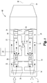
- Figure 1 is a schematic view of a turbine engine 10.
- the various unnumbered arrows illustrated in Figure 1 represent the direction of fluid flow through the turbine engine 10.
- the turbine engine 10 can produce power for several different kinds of applications, including vehicle propulsion and power generation, among others. It will be appreciated that the turbine engine 10 can be provided in any configuration, and can be used in any application. Also, embodiments of the present invention can be implemented with other types of engines such as reciprocating engines.
- the turbine engine 10 can include an inlet 12 with a fan 14 to receive fluid such as air.
- the fan 14 may be omitted from the turbine engine 10.
- the turbine engine 10 can also include a compressor section 16 to receive the fluid from the inlet 12 and compress the fluid.
- the turbine engine 10 can also include a combustor section 18 to receive the compressed fluid from the compressor section 16.
- the compressed fluid can be mixed with fuel from a fuel system 20 and ignited in a combustion chamber 22 defined by the combustor section 18.
- the turbine engine 10 can also include a turbine section 24 to receive the combustion gases from the combustor section 18. The energy associated with the combustion gases can be converted into kinetic energy (motion) in the turbine section 24.
- shafts 26, 28 are shown disposed for rotation about a centerline axis 30 of the turbine engine 10. Although only two shafts 26, 28 are shown, it will be appreciated that any number of shafts may be included within the turbine engine 10.
- the shafts 26, 28 can be journaled together for relative rotation.
- the shaft 26 can be a low pressure shaft supporting compressor blades 32 of a low pressure portion of the compressor section 16.
- the shaft 26 can also support low pressure turbine blades 34 of a low pressure portion of the turbine section 24.
- the shaft 28 encircles the shaft 26. Bearings (not shown) can be disposed between the shafts 26, 28.
- the shaft 28 can be a high pressure shaft supporting compressor blades 36 of a high pressure portion of the compressor section 16.
- the shaft 28 can also support high pressure turbine blades 38 of a high pressure portion of the turbine section 24.
- the turbine engine 10 defines a first fluid passageway (also referred to herein as a "primary fluid passageway"), extending along the axis 30 from the inlet 12 to an outlet 54.
- the exemplary first fluid passageway is defined in part by the compressor section 16 and the combustor section 18 and the turbine section 22.
- the first fluid passageway directs a first fluid stream through a core of the turbine engine 10.
- the first fluid stream can be air at the inlet 12 and through the compressor section 16.
- the first fluid stream can be a mixture of air and fuel in the combustor section 18.
- the first fluid stream can be exhaust gases through the turbine section 24 and the outlet in the exemplary embodiment of the invention.
- Figure 2 is a magnified schematic view of a combustor section of the turbine engine shown in Figure 1 .
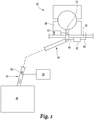
- Figure 3 is a magnified schematic view of the communications system shown in Figure 2 .
- a support member such as bearing 40
- the position of the bearing 40 along the axis 30 is selected for illustrative purposes only, and it will be appreciated that the bearing 40 can be positioned anywhere along the axis 30. It will also be appreciated that the support member can be any suitable mechanism or structure provided in addition to, or as an alternative to, the bearing 40.
- the exemplary bearing 40 and sump housing 42 are shown on one side of the shaft 28 to simplify the illustration. In practice, the bearing 40 and sump housing 42 can encircle the shaft 28. The sump housing 42 can seal against the shaft 28.
- the bearing 40 can receive a fluid such as a lubricant through a second fluid passageway 44 (also referred to herein as a "secondary fluid passageway").
- the second fluid passageway 44 can extend from a lubricant pump 46 to an outer race 48 of the bearing 40.
- the second fluid passageway 44 is disposed adjacent to the lubricant pump 46 and the outer race 48 of bearing 40.
- the second fluid passageway 44 can direct the lubricant from the lubricant pump 46 to the bearing 40.
- the lubricant pump 46 can receive lubricant from a lubricant tank (not shown) and/or can be part of a re-circulating lubricant system.
- a sensor 50 can be coupled to the bearing 40.
- the sensor 50 can be substantially encased and/or substantially encircled by a casing 60 formed of conductive material.
- the exemplary sensor 50 can be operable to sense at least one condition.
- the sensor 50 can be a vibration sensor for sensing the condition of the level of vibration of the bearing 40.
- the exemplary sensor 50 can be embedded in an outer race 48 of the bearing 40 (as illustrated), or can be fixed to an outer surface of the outer race 48.
- the senor 50 can be a part of a sensor assembly that also includes a transmitter 52 coupled to the sensor 50.
- the transmitter 52 can be operable to emit a signal corresponding to the at least one condition sensed by the sensor 50.
- At least a portion of the exemplary transmitter 52 can be disposed in the second fluid passageway 44 to emit the signal in the second fluid passageway 44 and through fluid that is disposed in the second fluid passageway 44.
- a receiver 56 operable to receive the signal emitted by the transmitter 52 can also be positioned in the second fluid passageway 44.
- the receiver 56 can be an antenna such as a microwave horn antenna or some other structure operable to capture a wireless signal.
- the receiver 56 can communicate with a data storage device and/or processor (generically identified at 58) so that the at least one condition sensed by the sensor 50 can be stored, monitored, evaluated, and/or processed appropriately.
- the data storage device and/or processor 58 can be located outside the turbine engine 10 or inside the turbine engine 10 and can communicate with the receiver 56 by way of a wired connection.
- Data communicated by the transmitter 52 which corresponds to the at least one condition sensed by the sensor 50, can be used for prognostics, health management, maintenance scheduling, fault identification and tolerance, research and design.
- the data storage device can include one or more components and can be of any volatile or nonvolatile type, including the solid state variety, the optical media variety, the magnetic variety, any combination of these, or such different arrangement as would occur to those skilled in the art.
- the processor may be configured to execute operating logic defining various prognostics, health management, maintenance scheduling, fault identification and tolerance, research and design functions. This operating logic may be in the form of dedicated hardware, such as a hardwired state machine, programming instructions, and/or a different form as would occur to those skilled in the art.
- the processor may be provided as a single component, or a collection of operatively coupled components; and may be comprised of digital circuitry, analog circuitry, or a hybrid combination of both of these types.
- the processor may have one or more components remotely located relative to the others.
- the processor can include multiple processing units arranged to operate independently, in a pipeline processing arrangement, in a parallel processing arrangement, and/or such different arrangement as would occur to those skilled in the art.
- the processor is a programmable microprocessing device of a solid-state, integrated circuit type that includes one or more processing units and memory.
- the processor can include one or more signal conditioners, modulators, demodulators, Arithmetic Logic Units (ALUs), Central Processing Units (CPUs), limiters, oscillators, control clocks, amplifiers, signal conditioners, filters, format converters, communication ports, clamps, delay devices, memory devices, and/or different circuitry or functional components as would occur to those skilled in the art.
- ALUs Arithmetic Logic Units
- CPUs Central Processing Units
- limiters oscillators, control clocks, amplifiers, signal conditioners, filters, format converters, communication ports, clamps, delay devices, memory devices, and/or different circuitry or functional components as would occur to those skilled in the art.
- signals can be wirelessly transmitted from the transmitter 52 of sensor assembly to the receiver 56 via the second fluid passageway 44, through lubricant that is disposed in the second fluid passageway 44.
- the exemplary second fluid passageway 44 can be used to direct lubricant (e.g., oil) to the bearing 40 and direct wireless signals away from a sensor assembly without interference by the casing 60.
- lubricant e.g., oil
- Exemplary types of oils that may be directed within the second fluid passageway 44 include hydrocarbon oil, polyalphaolefin (PAO) oil, or the like.
- the transmitter 52 can be configured to wirelessly communicate to the receiver 56 through other secondary fluid passageways that convey other types of fluids.
- passageways can convey other types of fluids such as fuel, coolant (e.g., liquid coolant, chemical coolant, gaseous cooling air, or the like), or the like.
- coolant e.g., liquid coolant, chemical coolant, gaseous cooling air, or the like
- the suitability of a particular secondary fluid passageway for directing wireless signals can be assessed based on the fluid disposed within the particular passageway. For example, a fluid such as water may detract from the suitability of a particular secondary fluid passageway for directing the wireless signal.
- the second fluid passageway 44 does not communicate with the first fluid passageway and is distinct from the first fluid passageway.
- secondary fluid passageways can be less than fully distinct from the primary fluid passageway.
- the secondary fluid passageway can be a bleed from the compressor section 16 shown in Figure 1 .
- the secondary fluid passageway can be an exhaust passageway downstream of one or more cylinders (i.e., primary fluid passageways) of a reciprocating engine.
- the exemplary second fluid passageway 44 is shown in Figures 2 and 3 as extending along a torturous path, including two relatively sharp changes in directions.
- the second fluid passageway 44 is also shown as extending axially and radially relative to a centerline axis 30 of the turbine engine 10.
- a signal emitted by the transmitter 52 travels to the receiver 56 along a distance greater than the shortest distance between the transmitter 52 and the receiver 56.
- cross-sectional dimensions of the second fluid passageway 44 (e.g., when viewed in along a longitudinal axis of the passageway) can be constant along at least part of its length.
- cross-sectional dimensions of the second fluid passageway 44 can be variable along at least part of its length.
- the transmitter 52 can be operable to emit a signal at a frequency that is substantially optimized relative to the cross sectional dimensions of the second fluid passageway 44 such that the second fluid passageway 44 functions as an electromagnetic waveguide.
- an "electromagnetic waveguide” or more simply “waveguide” refers to a structure such as a hollow metal conductor that provides a path along which electromagnetic signals having one or more frequencies (e.g., a radio frequency, a microwave frequency, or the like or a combination thereof) can be transmitted.
- the frequency of the signal emitted by the transmitter 52 can be selected based on the dimensions of the second fluid passageway 44 and the material from which the second fluid passageway 44 is formed.
- the dimensions of the second fluid passageway 44, and the material from which the second fluid passageway 44 is formed can be selected based on the frequency signal emitted by the transmitter 52. Accordingly, the second fluid passageway 44 can support any mode of signal transmission, and can also support multiple modes of signal coupling and transmission (e.g., electric field mode and/or magnetic field mode). It will be appreciated that numerous reference sources are available to one of ordinary skill in the art that correlate frequency, waveguide dimensions and waveguide material in order to successfully transmit a signal through a waveguide.
- the second fluid passageway 44 can have a circular cross-sectional dimension, a rectangular cross-sectional, or the like, or a combination thereof.
- the shape of the cross-sectional dimension of the second fluid passageway 44 can be variable or constant along at least a portion of the length of the second fluid passageway 44.
- Rectangular waveguides can be specified in WR numbers.
- the "WR” stands for “rectangular waveguide” and the number that follows is the dimension of the broad wall in mils, divided by 10.
- One mode of transmission in a rectangular waveguide is referenced as TE01.
- the lower cutoff wavelength and frequency for the TE01 mode is generally:
- the limits of operation for a rectangular waveguide are (approximately) between 125% and 189% of the lower cutoff frequency.
- the cut-off is 6.557 GHz
- the accepted band of operation is 8.2 to 12.4 GHz.
- the selection of the signal frequency is not compromised by how the secondary fluid passageway is shaped or how it bends. Also a secondary fluid passageway having a particular cross-sectional dimension may be suitable for transmitting signals at multiple frequencies.
- the second fluid passageway 44 can be formed from any suitable material.
- the second fluid passageway 44 is formed from copper, aluminum, silver, or the like, or a combination thereof.
- the second fluid passageway 44 can be formed with silver plating on an interior surface thereof to decrease resistance loss.
- the senor 50 can be provided as a vibration sensor configured to sense a single condition such as vibration of the bearing 40. Nevertheless, the sensor 50 can be any suitable sensor configured to sense one or more conditions. For example, the sensor 50 can be configured to sense one or more conditions such as temperature, strain, stress, torque, speed, voltage, current, force, flow, pressure, luminescence, color, image, displacement, radiation, or the like or a combination thereof.
- the senor 50 can be configured to sense a condition (i.e., vibration) that is not related directly to (i.e., is independent of, or is not a condition of) the fluid within the second fluid passageway 44. Nevertheless, the sensor 50 can be configured to sense one or more conditions that are related to the fluid within the second fluid passageway 44. For example, the sensor 50 can be configured to sense one or more conditions such as a temperature of the fluid within the second fluid passageway 44, a pressure of the fluid within the second fluid passageway 44, or the like, or a combination thereof.
- a condition i.e., vibration
- the sensor 50 can be configured to sense one or more conditions that are related to the fluid within the second fluid passageway 44.
- the sensor 50 can be configured to sense one or more conditions such as a temperature of the fluid within the second fluid passageway 44, a pressure of the fluid within the second fluid passageway 44, or the like, or a combination thereof.
- one or more of the components of the sensor assembly can be self-powered.
- the sensor 50 and/or the transmitter 52 can be self-powered.
- Energy scavenging methods such as thermo-electric conversion, can be applied to trickle charge an energy storage device (capacitor or battery) associated with the sensor 50 and/or the transmitter 52.
- Other powering devices for powering the sensor 50 and/or the transmitter 52 can include micro-generators, thermal electric generators, piezoelectric generators, or the like or a combination thereof.
- the senor assembly Upon having sufficient stored-energy, the senor assembly can sense a condition and/or transmit a signal. In one embodiment, a signal can be transmitted from the sensor assembly periodically (e.g., every five minutes).
- a sensor assembly can include a single sensor (e.g., sensor 50) operatively coupled to a transmitter 52. In other embodiments, however, a sensor assembly can include a multiple sensors operatively coupled to the same transmitter. In yet another embodiment, more than one sensor assembly may be provided, each of which including a transmitter emitting a signal within different secondary fluid passageways. Sensor assemblies (or components thereof) can apply simplex or duplex communication techniques. In still another embodiment, more than one sensor assembly may be provided, each of which including a transmitter emitting a signal within a common secondary fluid passageway.
- another sensor assembly (e.g., herein referred to as a "second sensor assembly") including a sensor 62, a probe 64 projecting into the sump housing 42 and a transmitter 66 may be provided in addition to the sensor assembly including the sensor 50 and transmitter 52 (e.g., herein referred to as a "first sensor assembly").
- the second sensor assembly can be operable to sense a condition different from the condition sensed by the first sensor assembly.
- the second sensor assembly can sense a temperature of the lubricant in the sump housing 42.
- the transmitter 66 can be operable to emit a signal corresponding to the condition of the temperature of lubricant in the sump housing 42.
- the frequencies with which signals are emitted by the transmitters 52 and 66 can be different.
- the frequencies of signals emitted by the transmitters 52 and 66 can be integer multipliers of one another.
- the second fluid passageway 44 can be configured to function as a waveguide for signals transmitted by both transmitters 52 and 66.
- a turbine engine comprising: a first fluid passageway having an inlet and an outlet; at least one combustion chamber positioned along said first fluid passageway between said inlet and said outlet, wherein a primary fluid stream passes through said first fluid passageway and said at least one combustion chamber for generating power; a second fluid passageway at least partially distinct from said first fluid passageway, wherein a secondary fluid stream passes through said second fluid passageway to support the generation of power; a sensor assembly having a sensor operable to sense at least one condition and a transmitter associated with said sensor and operable to emit a signal corresponding to the at least one condition wirelessly, wherein at least part of said transmitter is positioned in said second fluid passageway to transmit the signal through said second fluid passageway; and a receiver operable to receive the signal and positioned in the second fluid passageway; wherein said sensor assembly is further defined as being operable to emit the signal at a substantially optimized frequency relative to a cross-section of said second fluid passageway such that said second fluid passageway functions as
- the second fluid passageway can extend along a torturous path.
- the second fluid passageway can define a length and is a substantially constant cross-section along at least part of said length.
- the at least one sensed condition may be independent of the second fluid stream.
- the sensor assembly may be substantially encased in a structure formed of conductive material.
- the sensor assembly may further be defined as being operable to scavenge energy.
- the second fluid passageway can be one of a lubricant passageway, a coolant passageway, and a fuel passageway.
- a method of operating a turbine engine comprising: directing a first fluid stream through a core of the engine to generate power; passing a second fluid stream through a fluid passageway at least partially distinct from the core of the engine to support the generation of power during said directing; sensing at least one condition within the turbine engine with a sensor; transmitting a signal corresponding to the at least one condition wirelessly with a transmitter associated with the sensor; positioning the transmitter to transmit the signal through the fluid passageway; locating a receiver to receive the signal in the fluid passageway; and selecting the frequency of the signal based on the shape of the fluid passageway such that the fluid passageway functions as a waveguide.
- the sensing may include detecting a condition unaffected by the second fluid stream.
- the method may further include substantially encircling the transmitter with a structure formed of conductive material.
- the method may further include scavenging energy from within the turbine engine to power the sensor.
- the passing may include passing a second fluid stream of one of lubricant, coolant or fuel through the fluid passageway such that the sign emitted by the transmitter passes through the one of lubricant, coolant or fuel to reach the receiver.
- the turbine engine can include a first fluid passageway operable to direct a first fluid stream through a compressor section, a combustor section and a turbine section to generate power; a second fluid passageway at least partially distinct from the first fluid passageway, wherein a secondary fluid stream passes through the second fluid passageway to support the generation of power; at least one sensor assembly having a sensor operable to sense at least one condition and a transmitter associated with the sensor and operable to emit a signal corresponding to the at least one condition wirelessly, wherein at least part of the transmitter is positioned in the second fluid passageway to transmit the signal through the second fluid passageway; and a receiver operable to receive the signal and positioned in the second fluid passageway.
- the second fluid passageway can extend axially and radially relative to a centerline axis of the turbine engine.
- the second fluid passageway can have a substantially constant cross-section.
- a cross-section of the second fluid passageway may be configured such that the second fluid passageway operates as a waveguide for the signal.
- the at least one condition sensed by the sensor may be not a condition of the second fluid stream.
- the at least one sensor assembly may include a first sensor assembly having a first sensor operable to sense a first condition and a first transmitter associated with the first sensor and operable to emit a first signal corresponding to the first condition wirelessly at a first frequency, wherein at least part of the first transmitter is positioned in the second fluid passageway to transmit the first signal through the second fluid passageway; and a second sensor assembly having a second sensor operable to sense a second condition different than the first condition and a second transmitter associated with the second sensor and operable to emit a second signal corresponding to the second condition wirelessly at a second frequency different than the first frequency, wherein at least part of the second transmitter is positioned in the second fluid passageway to transmit the signal through the second fluid passageway, and wherein the first and second frequencies are integer multipliers of one another.
- the sensor communication system may include an electromagnetic waveguide disposed adjacent to at least one component of a machine, the electromagnetic waveguide being configured to convey a fluid within the machine; a sensor assembly including: a sensor operable to sense at least one condition; and a transmitter at least partially positioned in the electromagnetic waveguide, the transmitter being operatively coupled to the sensor and operable to emit a signal corresponding to the at least one condition; and a receiver at least partially positioned in the electromagnetic waveguide, the receiver being operable to wirelessly receive the signal.
- the machine may be a turbine engine.
- the senor may be operable to sense at least one condition of the machine.
- the senor may be operable to sense at least one condition of the fluid.
- the sensor communication system may further include a fluid source in fluid communication with the electromagnetic waveguide, wherein the electromagnetic waveguide is configured to convey the fluid from the fluid source.
- the fluid may include a fluid selected from the group consisting of a lubricant, a fuel and a coolant.
Landscapes
- Engineering & Computer Science (AREA)
- Mechanical Engineering (AREA)
- General Engineering & Computer Science (AREA)
- Arrangements For Transmission Of Measured Signals (AREA)
Claims (12)
- Moteur de turbine (10) comprenant :un premier passage de fluide possédant une entrée (12) et une sortie (54),au moins une chambre de combustion (22) positionnée le long dudit premier passage de fluide entre ladite entrée (12) et ladite sortie (54), un flux de fluide primaire passant à travers ledit premier passage de fluide et ladite au moins une chambre de combustion (22) pour produire de l'énergie,un second passage de fluide (44) distinct au moins en partie dudit premier passage de fluide, un flux de fluide secondaire passant à travers ledit second passage de fluide (44) pour soutenir la production d'énergie,un ensemble capteur comportant un capteur (50) conçu pour détecter au moins un état et un émetteur (52) associé au dit capteur (50) et conçu pour émettre sans fil un signal correspondant au au moins un état, une partie au moins dudit émetteur (52) étant positionnée dans ledit second passage de fluide (44) pour émettre le signal au travers dudit second passage de fluide (44), etun récepteur (56) conçu pour recevoir le signal et positionné dans le second passage de fluide (44),caractérisé en ce queledit ensemble capteur est en outre conçu et opérant pour émettre le signal à une fréquence sensiblement optimisée en fonction d'une section transversale dudit second passage de fluide (44) de telle sorte que ledit second passage de fluide (44) a une fonction de guide d'ondes.
- Moteur de turbine (10) selon la revendication 1, dans lequel ledit second passage de fluide (44) s'étend le long d'une trajectoire tortueuse.
- Moteur de turbine (10) selon la revendication 1, dans lequel ledit second passage de fluide définit une certaine longueur et a une section transversale sensiblement constante sur au moins une partie de ladite longueur.
- Moteur de turbine (10) selon la revendication 1, dans lequel le au moins un état détecté est indépendant du second flux de fluide.
- Moteur de turbine (10) selon la revendication 1, dans lequel ledit ensemble capteur est sensiblement encastré dans une structure constituée de matériau conducteur (60).
- Moteur de turbine (10) selon la revendication 1, dans lequel ledit ensemble capteur est en outre configuré pour inclure un dispositif de conversion thermoélectrique, un micro-générateur, un générateur électrique thermique, un générateur piézoélectrique ou une combinaison d'entre eux.
- Moteur de turbine (10) selon la revendication 1, dans lequel ledit second passage de fluide (44) est en outre conçu pour être l'un parmi un passage de lubrifiant, un passage de réfrigérant et un passage de carburant.
- Procédé pour faire fonctionner un moteur de turbine (10), comprenant les étapes consistant à :diriger un premier flux de fluide au travers d'un coeur de moteur pour produire de l'énergie,faire passer un second flux de fluide au travers d'un passage de fluide (44) distinct au moins en partie du coeur du moteur (10) pour soutenir la production d'énergie pendant ladite étape de direction,détecter au moins un état à l'intérieur du moteur de turbine (10) au moyen d'un capteur (50),émettre sans fil un signal correspondant au au moins un état au moyen d'un émetteur (52) associé au capteur (50),positionner l'émetteur (52) de façon à émettre le signal au travers du passage de fluide (44),placer un récepteur (56) de façon à recevoir le signal dans le passage de fluide (44), caractérisé par la sélection de la fréquence du signal en réaction à la forme du passage de fluide (44) de sorte que le passage de fluide (44) a une fonction de guide d'ondes.
- Procédé selon la revendication 8, dans lequel ladite étape de détection comprend la détection d'un état non affecté par le second flux de fluide.
- Procédé selon la revendication 8, comprenant en outre l'étape consistant à :entourer sensiblement l'émetteur (52) par une structure constituée de matériau conducteur (60).
- Procédé selon la revendication 8, comprenant en outre l'étape consistant à:utiliser un dispositif de conversion thermoélectrique, un micro-générateur, un générateur électrique thermique, un générateur piézoélectrique ou une combinaison d'entre eux pour tirer de l'énergie depuis l'intérieur du moteur de turbine (10) afin d'alimenter le capteur (50).
- Procédé selon la revendication 8, dans lequel ladite étape consistant à faire passer un second flux de fluide consiste à :faire passer un second flux de fluide de l'un parmi un lubrifiant, un réfrigérant ou un carburant au travers du passage de fluide (44) de façon à ce que le signal émis par l'émetteur (52) passe au travers de l'un parmi le lubrifiant, le réfrigérant ou le carburant pour atteindre le récepteur (56).
Applications Claiming Priority (2)
| Application Number | Priority Date | Filing Date | Title |
|---|---|---|---|
| US35096310P | 2010-06-03 | 2010-06-03 | |
| PCT/US2011/039167 WO2011153496A1 (fr) | 2010-06-03 | 2011-06-03 | Système de communication pour capteurs, et machine équipée de ce système |
Publications (3)
| Publication Number | Publication Date |
|---|---|
| EP2577023A1 EP2577023A1 (fr) | 2013-04-10 |
| EP2577023A4 EP2577023A4 (fr) | 2014-06-25 |
| EP2577023B1 true EP2577023B1 (fr) | 2018-05-30 |
Family
ID=45067099
Family Applications (1)
| Application Number | Title | Priority Date | Filing Date |
|---|---|---|---|
| EP11790510.9A Active EP2577023B1 (fr) | 2010-06-03 | 2011-06-03 | Système de communication pour capteurs, et machine équipée de ce système |
Country Status (4)
| Country | Link |
|---|---|
| US (1) | US9303523B2 (fr) |
| EP (1) | EP2577023B1 (fr) |
| CA (1) | CA2801572C (fr) |
| WO (1) | WO2011153496A1 (fr) |
Cited By (1)
| Publication number | Priority date | Publication date | Assignee | Title |
|---|---|---|---|---|
| US11619567B2 (en) | 2020-10-05 | 2023-04-04 | Raytheon Technologies Corporation | Multi-mode microwave waveguide blade sensing system |
Families Citing this family (21)
| Publication number | Priority date | Publication date | Assignee | Title |
|---|---|---|---|---|
| US20130299001A1 (en) * | 2012-05-08 | 2013-11-14 | Logimesh IP, LLC | Smart storage tank and drainage scheduling |
| GB201411342D0 (en) * | 2014-06-26 | 2014-08-13 | Rolls Royce Plc | Wireless communication system |
| GB201419214D0 (en) | 2014-10-29 | 2014-12-10 | Rolls Royce Plc | Bearing apparatus |
| DE102015207134A1 (de) * | 2015-04-20 | 2016-10-20 | Prüftechnik Dieter Busch AG | Verfahren zum Erfassen von Vibrationen einer Vorrichtung und Vibrationserfassungssystem |
| US10454525B2 (en) * | 2016-06-20 | 2019-10-22 | Ge Aviation Systems Llc | Communication of signals over fuel lines in a vehicle |
| DE102018202673B3 (de) * | 2018-02-22 | 2019-05-16 | Christian Maier GmbH & Co. KG | Drehdurchführung mit einem elektronischen Schnittstellenmodul zum Anschluss eines Sensors an ein IO-Link-System |
| US10830092B2 (en) * | 2018-03-07 | 2020-11-10 | General Electric Company | Bearing rotor thrust control |
| EP3726480A1 (fr) | 2019-04-17 | 2020-10-21 | United Technologies Corporation | Mises à jour à distance d'un moteur à turbine à gaz |
| US11913643B2 (en) | 2019-04-17 | 2024-02-27 | Rtx Corporation | Engine wireless sensor system with energy harvesting |
| EP3726325B1 (fr) | 2019-04-17 | 2022-08-24 | Raytheon Technologies Corporation | Moteur à turbine à gaz comportant un enregistrement dynamique des données |
| US11208916B2 (en) | 2019-04-17 | 2021-12-28 | Raytheon Technologies Corporation | Self-healing remote dynamic data recording |
| US10977877B2 (en) | 2019-04-17 | 2021-04-13 | Raytheon Technologies Corporation | Engine gateway with engine data storage |
| US11492132B2 (en) | 2019-04-17 | 2022-11-08 | Raytheon Technologies Corporation | Gas turbine engine configuration data synchronization with a ground-based system |
| EP3726324B1 (fr) | 2019-04-17 | 2023-03-01 | Raytheon Technologies Corporation | Passerelle de communication d'un moteur à turbine à gaz avec capteurs internes |
| EP3726323B1 (fr) | 2019-04-17 | 2023-03-08 | Raytheon Technologies Corporation | Gateway de communication d'un moteur à turbine à gaz doté d'antennes intégrales |
| CN110821582A (zh) * | 2019-11-18 | 2020-02-21 | 福建福清核电有限公司 | 一种汽轮机润滑油温度调节阀的稳定控制方法 |
| US11698348B2 (en) | 2020-10-05 | 2023-07-11 | Raytheon Technologies Corporation | Self-referencing microwave sensing system |
| US11575277B2 (en) | 2020-10-05 | 2023-02-07 | Raytheon Technologies Corporation | Node power extraction in a waveguide system |
| US11303311B1 (en) | 2020-10-05 | 2022-04-12 | Raytheon Technologies Corporation | Radio frequency interface to sensor |
| US11265380B1 (en) | 2020-10-05 | 2022-03-01 | Raytheon Technologies Corporation | Radio frequency waveguide system for mixed temperature environments |
| US11509032B2 (en) | 2020-10-16 | 2022-11-22 | Raytheon Technologies Corporation | Radio frequency waveguide system including control remote node thermal cooling |
Citations (7)
| Publication number | Priority date | Publication date | Assignee | Title |
|---|---|---|---|---|
| US4561246A (en) | 1983-12-23 | 1985-12-31 | United Technologies Corporation | Bearing compartment for a gas turbine engine |
| US5069070A (en) | 1988-12-09 | 1991-12-03 | Fev Motorentechnik Gmbh Kg | Method for determining the alcohol content and/or the calorific value of fuels via propagation parameters |
| US20050213548A1 (en) | 2004-03-24 | 2005-09-29 | Benson Dwayne M | Aircraft engine sensor network using wireless sensor communication modules |
| US20070209865A1 (en) | 2005-12-20 | 2007-09-13 | George Kokosalakis | Communications and power harvesting system for in-pipe wireless sensor networks |
| US7287384B2 (en) | 2004-12-13 | 2007-10-30 | Pratt & Whitney Canada Corp. | Bearing chamber pressurization system |
| US20080054645A1 (en) | 2006-09-06 | 2008-03-06 | Siemens Power Generation, Inc. | Electrical assembly for monitoring conditions in a combustion turbine operating environment |
| EP2189628A2 (fr) | 2008-11-21 | 2010-05-26 | Rolls-Royce plc | Moteur à turbine à gaz avec un système de transmission de signal comprenant un guide d'onde |
Family Cites Families (21)
| Publication number | Priority date | Publication date | Assignee | Title |
|---|---|---|---|---|
| FR2076450A5 (fr) * | 1970-01-15 | 1971-10-15 | Snecma | |
| US5103181A (en) * | 1988-10-05 | 1992-04-07 | Den Norske Oljeselskap A. S. | Composition monitor and monitoring process using impedance measurements |
| US5120975A (en) * | 1990-03-23 | 1992-06-09 | General Electric Company | Gas turbine flame detection system with reflected flame radiation attenuator |
| GB9122210D0 (en) * | 1991-10-18 | 1991-11-27 | Marconi Gec Ltd | Method for measurement of the gas and water content in oil |
| US5845480A (en) * | 1996-03-13 | 1998-12-08 | Unison Industries Limited Partnership | Ignition methods and apparatus using microwave and laser energy |
| JPH11166705A (ja) * | 1997-12-03 | 1999-06-22 | Zenshin Denryoku Engineering:Kk | 水−化石燃料混合エマルジョンの燃焼方法及び燃焼装置 |
| US6189510B1 (en) * | 1999-07-09 | 2001-02-20 | Brunswick Corporation | Fuel distribution system with flexible metallic conduits for an internal combustion engine |
| DE50115614D1 (de) * | 2001-04-17 | 2010-10-14 | Alstom Technology Ltd | Verfahren zur Unterdrückung von Verbrennungsfluktuationen in einer Gasturbine |
| US6642720B2 (en) | 2001-07-25 | 2003-11-04 | General Electric Company | Wireless sensor assembly for circumferential monitoring of gas stream properties |
| US7017415B2 (en) | 2001-09-27 | 2006-03-28 | Siemens Westinghouse Power Corporation | Apparatus for sensing pressure fluctuations in a hostile environment |
| US6717418B2 (en) * | 2001-11-16 | 2004-04-06 | General Electric Company | Method and apparatus for measuring turbine blade tip clearance |
| US6820431B2 (en) * | 2002-10-31 | 2004-11-23 | General Electric Company | Acoustic impedance-matched fuel nozzle device and tunable fuel injection resonator assembly |
| US8004423B2 (en) * | 2004-06-21 | 2011-08-23 | Siemens Energy, Inc. | Instrumented component for use in an operating environment |
| US7634913B2 (en) * | 2005-03-30 | 2009-12-22 | General Electric Company | Bearing assembly and method of monitoring same |
| WO2006112971A2 (fr) * | 2005-04-13 | 2006-10-26 | Corning Incorporated | Systeme d'adaptation de mode pour laser a cavite externe reglable |
| DE102006046695B4 (de) * | 2006-09-29 | 2008-09-11 | Siemens Ag | Vorrichtung zur Bestimmung des Abstands zwischen mindestens einer Laufschaufel und einer die mindestens eine Laufschaufel umgebenden Wandung einer Gasturbine sowie Verwendung der Vorrichtung |
| DE102006046696A1 (de) * | 2006-09-29 | 2008-04-17 | Siemens Ag | Vorrichtung zur Bestimmung des Abstands zwischen mindestens einer Laufschaufel und einer die mindestens eine Laufschaufel umgebenden Wandung einer Strömungsmaschine |
| US7854127B2 (en) * | 2006-10-24 | 2010-12-21 | United Technologies Corporation | Smart wireless engine sensor |
| US8565998B2 (en) | 2006-11-27 | 2013-10-22 | United Technologies Corporation | Gas turbine engine having on-engine data storage device |
| GB2466404B (en) | 2007-11-21 | 2010-10-27 | Rolls Royce Plc | Turbomachine having an apparatus to measure the clearance between a rotor blade tip and a stator liner of a stator casing |
| GB0917879D0 (en) * | 2009-10-13 | 2009-11-25 | Airbus Uk Ltd | Aircraft fuel system |
-
2011
- 2011-06-03 EP EP11790510.9A patent/EP2577023B1/fr active Active
- 2011-06-03 CA CA2801572A patent/CA2801572C/fr active Active
- 2011-06-03 WO PCT/US2011/039167 patent/WO2011153496A1/fr active Application Filing
- 2011-06-03 US US13/153,223 patent/US9303523B2/en active Active
Patent Citations (7)
| Publication number | Priority date | Publication date | Assignee | Title |
|---|---|---|---|---|
| US4561246A (en) | 1983-12-23 | 1985-12-31 | United Technologies Corporation | Bearing compartment for a gas turbine engine |
| US5069070A (en) | 1988-12-09 | 1991-12-03 | Fev Motorentechnik Gmbh Kg | Method for determining the alcohol content and/or the calorific value of fuels via propagation parameters |
| US20050213548A1 (en) | 2004-03-24 | 2005-09-29 | Benson Dwayne M | Aircraft engine sensor network using wireless sensor communication modules |
| US7287384B2 (en) | 2004-12-13 | 2007-10-30 | Pratt & Whitney Canada Corp. | Bearing chamber pressurization system |
| US20070209865A1 (en) | 2005-12-20 | 2007-09-13 | George Kokosalakis | Communications and power harvesting system for in-pipe wireless sensor networks |
| US20080054645A1 (en) | 2006-09-06 | 2008-03-06 | Siemens Power Generation, Inc. | Electrical assembly for monitoring conditions in a combustion turbine operating environment |
| EP2189628A2 (fr) | 2008-11-21 | 2010-05-26 | Rolls-Royce plc | Moteur à turbine à gaz avec un système de transmission de signal comprenant un guide d'onde |
Non-Patent Citations (1)
| Title |
|---|
| ANDREAS LINKE-DIESINGER: "Systems of commercial Turbofan Engines", 2008, SPRINGER-VERLAG BERLIN HEIDELBERG, article "2.1.3 Bearing Compartment Pressurization", pages: 28 |
Cited By (1)
| Publication number | Priority date | Publication date | Assignee | Title |
|---|---|---|---|---|
| US11619567B2 (en) | 2020-10-05 | 2023-04-04 | Raytheon Technologies Corporation | Multi-mode microwave waveguide blade sensing system |
Also Published As
| Publication number | Publication date |
|---|---|
| CA2801572A1 (fr) | 2011-12-08 |
| WO2011153496A1 (fr) | 2011-12-08 |
| EP2577023A1 (fr) | 2013-04-10 |
| EP2577023A4 (fr) | 2014-06-25 |
| US20120079830A1 (en) | 2012-04-05 |
| CA2801572C (fr) | 2019-01-15 |
| US9303523B2 (en) | 2016-04-05 |
Similar Documents
| Publication | Publication Date | Title |
|---|---|---|
| EP2577023B1 (fr) | Système de communication pour capteurs, et machine équipée de ce système | |
| EP3111075B1 (fr) | Réseau sans fil protégé | |
| US7368827B2 (en) | Electrical assembly for monitoring conditions in a combustion turbine operating environment | |
| US9121769B2 (en) | Sensor and antenna arrangement | |
| CN102577033B (zh) | 集成无刷式起动器/发电器系统 | |
| US7224082B2 (en) | Turbomachine including an integrated electricity generator | |
| CN102308401B (zh) | 燃气涡轮的热电生成 | |
| US20060138779A1 (en) | Two-spool bypass turbojet with a rear electricity generator, and an air flow connection device and system | |
| US20150244344A1 (en) | Self-powered sensing and transmitting device and method of fabricating the same | |
| CN104246176A (zh) | 包括温差发电机的涡轮发动机 | |
| JP2013181537A (ja) | 装置および関連する監視システム | |
| US9320181B1 (en) | System and method for dissipating thermal energy away from electronic components in a rotatable shaft | |
| US20150084340A1 (en) | Load apparatus and method of using same | |
| EP3291363B1 (fr) | Communication électromagnétique par guide d'ondes | |
| US9041384B2 (en) | Sensors for high-temperature environments and method for assembling same | |
| EP3291040B1 (fr) | Communication électromagnétique au travers de composants d'une machine | |
| US10544706B2 (en) | Single shaft combined cycle power plant shaft arrangement | |
| KR101891921B1 (ko) | 터빈 장치의 블레이드 진동 측정 장치 | |
| EP3291484A1 (fr) | Protection contre la contrefaçon de composants | |
| WO2016086336A1 (fr) | Appareil électrique à utiliser dans une turbine à combustion et procédé de surveillance d'un composant de turbine à combustion | |
| EP3291571A1 (fr) | Composite céramique métallique pour matériaux transparents à signal électromagnétique |
Legal Events
| Date | Code | Title | Description |
|---|---|---|---|
| PUAI | Public reference made under article 153(3) epc to a published international application that has entered the european phase |
Free format text: ORIGINAL CODE: 0009012 |
|
| 17P | Request for examination filed |
Effective date: 20130103 |
|
| AK | Designated contracting states |
Kind code of ref document: A1 Designated state(s): AL AT BE BG CH CY CZ DE DK EE ES FI FR GB GR HR HU IE IS IT LI LT LU LV MC MK MT NL NO PL PT RO RS SE SI SK SM TR |
|
| DAX | Request for extension of the european patent (deleted) | ||
| A4 | Supplementary search report drawn up and despatched |
Effective date: 20140523 |
|
| RIC1 | Information provided on ipc code assigned before grant |
Ipc: F01D 25/16 20060101ALI20140519BHEP Ipc: F01D 17/20 20060101ALI20140519BHEP Ipc: F01D 17/02 20060101ALI20140519BHEP Ipc: F02C 6/00 20060101AFI20140519BHEP |
|
| GRAP | Despatch of communication of intention to grant a patent |
Free format text: ORIGINAL CODE: EPIDOSNIGR1 |
|
| STAA | Information on the status of an ep patent application or granted ep patent |
Free format text: STATUS: GRANT OF PATENT IS INTENDED |
|
| RIC1 | Information provided on ipc code assigned before grant |
Ipc: F01D 25/16 20060101ALI20161107BHEP Ipc: F02C 6/00 20060101AFI20161107BHEP Ipc: F01D 17/20 20060101ALI20161107BHEP Ipc: H04Q 9/00 20060101ALI20161107BHEP Ipc: F23M 11/04 20060101ALI20161107BHEP Ipc: F01D 17/08 20060101ALI20161107BHEP Ipc: F01D 17/02 20060101ALI20161107BHEP |
|
| INTG | Intention to grant announced |
Effective date: 20161201 |
|
| GRAJ | Information related to disapproval of communication of intention to grant by the applicant or resumption of examination proceedings by the epo deleted |
Free format text: ORIGINAL CODE: EPIDOSDIGR1 |
|
| STAA | Information on the status of an ep patent application or granted ep patent |
Free format text: STATUS: REQUEST FOR EXAMINATION WAS MADE |
|
| INTC | Intention to grant announced (deleted) | ||
| GRAR | Information related to intention to grant a patent recorded |
Free format text: ORIGINAL CODE: EPIDOSNIGR71 |
|
| GRAS | Grant fee paid |
Free format text: ORIGINAL CODE: EPIDOSNIGR3 |
|
| STAA | Information on the status of an ep patent application or granted ep patent |
Free format text: STATUS: GRANT OF PATENT IS INTENDED |
|
| GRAA | (expected) grant |
Free format text: ORIGINAL CODE: 0009210 |
|
| STAA | Information on the status of an ep patent application or granted ep patent |
Free format text: STATUS: THE PATENT HAS BEEN GRANTED |
|
| INTG | Intention to grant announced |
Effective date: 20180419 |
|
| AK | Designated contracting states |
Kind code of ref document: B1 Designated state(s): AL AT BE BG CH CY CZ DE DK EE ES FI FR GB GR HR HU IE IS IT LI LT LU LV MC MK MT NL NO PL PT RO RS SE SI SK SM TR |
|
| REG | Reference to a national code |
Ref country code: GB Ref legal event code: FG4D |
|
| REG | Reference to a national code |
Ref country code: CH Ref legal event code: EP |
|
| REG | Reference to a national code |
Ref country code: AT Ref legal event code: REF Ref document number: 1003831 Country of ref document: AT Kind code of ref document: T Effective date: 20180615 |
|
| REG | Reference to a national code |
Ref country code: FR Ref legal event code: PLFP Year of fee payment: 8 |
|
| REG | Reference to a national code |
Ref country code: IE Ref legal event code: FG4D |
|
| REG | Reference to a national code |
Ref country code: DE Ref legal event code: R096 Ref document number: 602011048864 Country of ref document: DE |
|
| REG | Reference to a national code |
Ref country code: NL Ref legal event code: MP Effective date: 20180530 |
|
| REG | Reference to a national code |
Ref country code: LT Ref legal event code: MG4D |
|
| PG25 | Lapsed in a contracting state [announced via postgrant information from national office to epo] |
Ref country code: ES Free format text: LAPSE BECAUSE OF FAILURE TO SUBMIT A TRANSLATION OF THE DESCRIPTION OR TO PAY THE FEE WITHIN THE PRESCRIBED TIME-LIMIT Effective date: 20180530 Ref country code: SE Free format text: LAPSE BECAUSE OF FAILURE TO SUBMIT A TRANSLATION OF THE DESCRIPTION OR TO PAY THE FEE WITHIN THE PRESCRIBED TIME-LIMIT Effective date: 20180530 Ref country code: NO Free format text: LAPSE BECAUSE OF FAILURE TO SUBMIT A TRANSLATION OF THE DESCRIPTION OR TO PAY THE FEE WITHIN THE PRESCRIBED TIME-LIMIT Effective date: 20180830 Ref country code: FI Free format text: LAPSE BECAUSE OF FAILURE TO SUBMIT A TRANSLATION OF THE DESCRIPTION OR TO PAY THE FEE WITHIN THE PRESCRIBED TIME-LIMIT Effective date: 20180530 Ref country code: LT Free format text: LAPSE BECAUSE OF FAILURE TO SUBMIT A TRANSLATION OF THE DESCRIPTION OR TO PAY THE FEE WITHIN THE PRESCRIBED TIME-LIMIT Effective date: 20180530 Ref country code: BG Free format text: LAPSE BECAUSE OF FAILURE TO SUBMIT A TRANSLATION OF THE DESCRIPTION OR TO PAY THE FEE WITHIN THE PRESCRIBED TIME-LIMIT Effective date: 20180830 Ref country code: CY Free format text: LAPSE BECAUSE OF FAILURE TO SUBMIT A TRANSLATION OF THE DESCRIPTION OR TO PAY THE FEE WITHIN THE PRESCRIBED TIME-LIMIT Effective date: 20180530 |
|
| PG25 | Lapsed in a contracting state [announced via postgrant information from national office to epo] |
Ref country code: GR Free format text: LAPSE BECAUSE OF FAILURE TO SUBMIT A TRANSLATION OF THE DESCRIPTION OR TO PAY THE FEE WITHIN THE PRESCRIBED TIME-LIMIT Effective date: 20180831 Ref country code: HR Free format text: LAPSE BECAUSE OF FAILURE TO SUBMIT A TRANSLATION OF THE DESCRIPTION OR TO PAY THE FEE WITHIN THE PRESCRIBED TIME-LIMIT Effective date: 20180530 Ref country code: RS Free format text: LAPSE BECAUSE OF FAILURE TO SUBMIT A TRANSLATION OF THE DESCRIPTION OR TO PAY THE FEE WITHIN THE PRESCRIBED TIME-LIMIT Effective date: 20180530 Ref country code: LV Free format text: LAPSE BECAUSE OF FAILURE TO SUBMIT A TRANSLATION OF THE DESCRIPTION OR TO PAY THE FEE WITHIN THE PRESCRIBED TIME-LIMIT Effective date: 20180530 |
|
| REG | Reference to a national code |
Ref country code: AT Ref legal event code: MK05 Ref document number: 1003831 Country of ref document: AT Kind code of ref document: T Effective date: 20180530 |
|
| PG25 | Lapsed in a contracting state [announced via postgrant information from national office to epo] |
Ref country code: NL Free format text: LAPSE BECAUSE OF FAILURE TO SUBMIT A TRANSLATION OF THE DESCRIPTION OR TO PAY THE FEE WITHIN THE PRESCRIBED TIME-LIMIT Effective date: 20180530 |
|
| REG | Reference to a national code |
Ref country code: DE Ref legal event code: R119 Ref document number: 602011048864 Country of ref document: DE |
|
| PG25 | Lapsed in a contracting state [announced via postgrant information from national office to epo] |
Ref country code: CZ Free format text: LAPSE BECAUSE OF FAILURE TO SUBMIT A TRANSLATION OF THE DESCRIPTION OR TO PAY THE FEE WITHIN THE PRESCRIBED TIME-LIMIT Effective date: 20180530 Ref country code: SK Free format text: LAPSE BECAUSE OF FAILURE TO SUBMIT A TRANSLATION OF THE DESCRIPTION OR TO PAY THE FEE WITHIN THE PRESCRIBED TIME-LIMIT Effective date: 20180530 Ref country code: RO Free format text: LAPSE BECAUSE OF FAILURE TO SUBMIT A TRANSLATION OF THE DESCRIPTION OR TO PAY THE FEE WITHIN THE PRESCRIBED TIME-LIMIT Effective date: 20180530 Ref country code: AT Free format text: LAPSE BECAUSE OF FAILURE TO SUBMIT A TRANSLATION OF THE DESCRIPTION OR TO PAY THE FEE WITHIN THE PRESCRIBED TIME-LIMIT Effective date: 20180530 Ref country code: EE Free format text: LAPSE BECAUSE OF FAILURE TO SUBMIT A TRANSLATION OF THE DESCRIPTION OR TO PAY THE FEE WITHIN THE PRESCRIBED TIME-LIMIT Effective date: 20180530 Ref country code: DK Free format text: LAPSE BECAUSE OF FAILURE TO SUBMIT A TRANSLATION OF THE DESCRIPTION OR TO PAY THE FEE WITHIN THE PRESCRIBED TIME-LIMIT Effective date: 20180530 Ref country code: PL Free format text: LAPSE BECAUSE OF FAILURE TO SUBMIT A TRANSLATION OF THE DESCRIPTION OR TO PAY THE FEE WITHIN THE PRESCRIBED TIME-LIMIT Effective date: 20180530 |
|
| REG | Reference to a national code |
Ref country code: CH Ref legal event code: PL |
|
| PLBI | Opposition filed |
Free format text: ORIGINAL CODE: 0009260 |
|
| PG25 | Lapsed in a contracting state [announced via postgrant information from national office to epo] |
Ref country code: IT Free format text: LAPSE BECAUSE OF FAILURE TO SUBMIT A TRANSLATION OF THE DESCRIPTION OR TO PAY THE FEE WITHIN THE PRESCRIBED TIME-LIMIT Effective date: 20180530 Ref country code: SM Free format text: LAPSE BECAUSE OF FAILURE TO SUBMIT A TRANSLATION OF THE DESCRIPTION OR TO PAY THE FEE WITHIN THE PRESCRIBED TIME-LIMIT Effective date: 20180530 |
|
| REG | Reference to a national code |
Ref country code: BE Ref legal event code: MM Effective date: 20180630 |
|
| PLAX | Notice of opposition and request to file observation + time limit sent |
Free format text: ORIGINAL CODE: EPIDOSNOBS2 |
|
| 26 | Opposition filed |
Opponent name: UNITED TECHNOLOGIES CORPORATION Effective date: 20190208 |
|
| REG | Reference to a national code |
Ref country code: IE Ref legal event code: MM4A |
|
| PG25 | Lapsed in a contracting state [announced via postgrant information from national office to epo] |
Ref country code: MC Free format text: LAPSE BECAUSE OF FAILURE TO SUBMIT A TRANSLATION OF THE DESCRIPTION OR TO PAY THE FEE WITHIN THE PRESCRIBED TIME-LIMIT Effective date: 20180530 Ref country code: LU Free format text: LAPSE BECAUSE OF NON-PAYMENT OF DUE FEES Effective date: 20180603 |
|
| GBPC | Gb: european patent ceased through non-payment of renewal fee |
Effective date: 20180830 |
|
| PG25 | Lapsed in a contracting state [announced via postgrant information from national office to epo] |
Ref country code: IE Free format text: LAPSE BECAUSE OF NON-PAYMENT OF DUE FEES Effective date: 20180603 Ref country code: LI Free format text: LAPSE BECAUSE OF NON-PAYMENT OF DUE FEES Effective date: 20180630 Ref country code: CH Free format text: LAPSE BECAUSE OF NON-PAYMENT OF DUE FEES Effective date: 20180630 Ref country code: DE Free format text: LAPSE BECAUSE OF NON-PAYMENT OF DUE FEES Effective date: 20190101 |
|
| PLBB | Reply of patent proprietor to notice(s) of opposition received |
Free format text: ORIGINAL CODE: EPIDOSNOBS3 |
|
| PG25 | Lapsed in a contracting state [announced via postgrant information from national office to epo] |
Ref country code: BE Free format text: LAPSE BECAUSE OF NON-PAYMENT OF DUE FEES Effective date: 20180630 Ref country code: SI Free format text: LAPSE BECAUSE OF FAILURE TO SUBMIT A TRANSLATION OF THE DESCRIPTION OR TO PAY THE FEE WITHIN THE PRESCRIBED TIME-LIMIT Effective date: 20180530 |
|
| PG25 | Lapsed in a contracting state [announced via postgrant information from national office to epo] |
Ref country code: GB Free format text: LAPSE BECAUSE OF NON-PAYMENT OF DUE FEES Effective date: 20180830 |
|
| PG25 | Lapsed in a contracting state [announced via postgrant information from national office to epo] |
Ref country code: AL Free format text: LAPSE BECAUSE OF FAILURE TO SUBMIT A TRANSLATION OF THE DESCRIPTION OR TO PAY THE FEE WITHIN THE PRESCRIBED TIME-LIMIT Effective date: 20180530 |
|
| PG25 | Lapsed in a contracting state [announced via postgrant information from national office to epo] |
Ref country code: MT Free format text: LAPSE BECAUSE OF NON-PAYMENT OF DUE FEES Effective date: 20180603 |
|
| PG25 | Lapsed in a contracting state [announced via postgrant information from national office to epo] |
Ref country code: TR Free format text: LAPSE BECAUSE OF FAILURE TO SUBMIT A TRANSLATION OF THE DESCRIPTION OR TO PAY THE FEE WITHIN THE PRESCRIBED TIME-LIMIT Effective date: 20180530 |
|
| PG25 | Lapsed in a contracting state [announced via postgrant information from national office to epo] |
Ref country code: HU Free format text: LAPSE BECAUSE OF FAILURE TO SUBMIT A TRANSLATION OF THE DESCRIPTION OR TO PAY THE FEE WITHIN THE PRESCRIBED TIME-LIMIT; INVALID AB INITIO Effective date: 20110603 Ref country code: PT Free format text: LAPSE BECAUSE OF FAILURE TO SUBMIT A TRANSLATION OF THE DESCRIPTION OR TO PAY THE FEE WITHIN THE PRESCRIBED TIME-LIMIT Effective date: 20180530 |
|
| PG25 | Lapsed in a contracting state [announced via postgrant information from national office to epo] |
Ref country code: MK Free format text: LAPSE BECAUSE OF NON-PAYMENT OF DUE FEES Effective date: 20180530 |
|
| PG25 | Lapsed in a contracting state [announced via postgrant information from national office to epo] |
Ref country code: IS Free format text: LAPSE BECAUSE OF FAILURE TO SUBMIT A TRANSLATION OF THE DESCRIPTION OR TO PAY THE FEE WITHIN THE PRESCRIBED TIME-LIMIT Effective date: 20180930 |
|
| PLAB | Opposition data, opponent's data or that of the opponent's representative modified |
Free format text: ORIGINAL CODE: 0009299OPPO |
|
| R26 | Opposition filed (corrected) |
Opponent name: RAYTHEON TECHNOLOGIES CORPORATION Effective date: 20200724 |
|
| PLCK | Communication despatched that opposition was rejected |
Free format text: ORIGINAL CODE: EPIDOSNREJ1 |
|
| APAH | Appeal reference modified |
Free format text: ORIGINAL CODE: EPIDOSCREFNO |
|
| APBM | Appeal reference recorded |
Free format text: ORIGINAL CODE: EPIDOSNREFNO |
|
| APBP | Date of receipt of notice of appeal recorded |
Free format text: ORIGINAL CODE: EPIDOSNNOA2O |
|
| APBQ | Date of receipt of statement of grounds of appeal recorded |
Free format text: ORIGINAL CODE: EPIDOSNNOA3O |
|
| APBU | Appeal procedure closed |
Free format text: ORIGINAL CODE: EPIDOSNNOA9O |
|
| PLBN | Opposition rejected |
Free format text: ORIGINAL CODE: 0009273 |
|
| STAA | Information on the status of an ep patent application or granted ep patent |
Free format text: STATUS: OPPOSITION REJECTED |
|
| 27O | Opposition rejected |
Effective date: 20230418 |
|
| P01 | Opt-out of the competence of the unified patent court (upc) registered |
Effective date: 20230528 |
|
| PGFP | Annual fee paid to national office [announced via postgrant information from national office to epo] |
Ref country code: FR Payment date: 20230622 Year of fee payment: 13 |