EP2575682B1 - Transcatheter delivery system with controlled expansion and contraction of prosthetic heart valve - Google Patents
Transcatheter delivery system with controlled expansion and contraction of prosthetic heart valve Download PDFInfo
- Publication number
- EP2575682B1 EP2575682B1 EP11724908.6A EP11724908A EP2575682B1 EP 2575682 B1 EP2575682 B1 EP 2575682B1 EP 11724908 A EP11724908 A EP 11724908A EP 2575682 B1 EP2575682 B1 EP 2575682B1
- Authority
- EP
- European Patent Office
- Prior art keywords
- heart valve
- prosthetic heart
- coupling structure
- distal end
- delivery system
- Prior art date
- Legal status (The legal status is an assumption and is not a legal conclusion. Google has not performed a legal analysis and makes no representation as to the accuracy of the status listed.)
- Active
Links
Images


Classifications
-
- A—HUMAN NECESSITIES
- A61—MEDICAL OR VETERINARY SCIENCE; HYGIENE
- A61F—FILTERS IMPLANTABLE INTO BLOOD VESSELS; PROSTHESES; DEVICES PROVIDING PATENCY TO, OR PREVENTING COLLAPSING OF, TUBULAR STRUCTURES OF THE BODY, e.g. STENTS; ORTHOPAEDIC, NURSING OR CONTRACEPTIVE DEVICES; FOMENTATION; TREATMENT OR PROTECTION OF EYES OR EARS; BANDAGES, DRESSINGS OR ABSORBENT PADS; FIRST-AID KITS
- A61F2/00—Filters implantable into blood vessels; Prostheses, i.e. artificial substitutes or replacements for parts of the body; Appliances for connecting them with the body; Devices providing patency to, or preventing collapsing of, tubular structures of the body, e.g. stents
- A61F2/02—Prostheses implantable into the body
- A61F2/24—Heart valves ; Vascular valves, e.g. venous valves; Heart implants, e.g. passive devices for improving the function of the native valve or the heart muscle; Transmyocardial revascularisation [TMR] devices; Valves implantable in the body
- A61F2/2427—Devices for manipulating or deploying heart valves during implantation
- A61F2/2436—Deployment by retracting a sheath
-
- A—HUMAN NECESSITIES
- A61—MEDICAL OR VETERINARY SCIENCE; HYGIENE
- A61F—FILTERS IMPLANTABLE INTO BLOOD VESSELS; PROSTHESES; DEVICES PROVIDING PATENCY TO, OR PREVENTING COLLAPSING OF, TUBULAR STRUCTURES OF THE BODY, e.g. STENTS; ORTHOPAEDIC, NURSING OR CONTRACEPTIVE DEVICES; FOMENTATION; TREATMENT OR PROTECTION OF EYES OR EARS; BANDAGES, DRESSINGS OR ABSORBENT PADS; FIRST-AID KITS
- A61F2/00—Filters implantable into blood vessels; Prostheses, i.e. artificial substitutes or replacements for parts of the body; Appliances for connecting them with the body; Devices providing patency to, or preventing collapsing of, tubular structures of the body, e.g. stents
- A61F2/02—Prostheses implantable into the body
- A61F2/24—Heart valves ; Vascular valves, e.g. venous valves; Heart implants, e.g. passive devices for improving the function of the native valve or the heart muscle; Transmyocardial revascularisation [TMR] devices; Valves implantable in the body
- A61F2/2412—Heart valves ; Vascular valves, e.g. venous valves; Heart implants, e.g. passive devices for improving the function of the native valve or the heart muscle; Transmyocardial revascularisation [TMR] devices; Valves implantable in the body with soft flexible valve members, e.g. tissue valves shaped like natural valves
- A61F2/2418—Scaffolds therefor, e.g. support stents
-
- A—HUMAN NECESSITIES
- A61—MEDICAL OR VETERINARY SCIENCE; HYGIENE
- A61F—FILTERS IMPLANTABLE INTO BLOOD VESSELS; PROSTHESES; DEVICES PROVIDING PATENCY TO, OR PREVENTING COLLAPSING OF, TUBULAR STRUCTURES OF THE BODY, e.g. STENTS; ORTHOPAEDIC, NURSING OR CONTRACEPTIVE DEVICES; FOMENTATION; TREATMENT OR PROTECTION OF EYES OR EARS; BANDAGES, DRESSINGS OR ABSORBENT PADS; FIRST-AID KITS
- A61F2/00—Filters implantable into blood vessels; Prostheses, i.e. artificial substitutes or replacements for parts of the body; Appliances for connecting them with the body; Devices providing patency to, or preventing collapsing of, tubular structures of the body, e.g. stents
- A61F2/02—Prostheses implantable into the body
- A61F2/24—Heart valves ; Vascular valves, e.g. venous valves; Heart implants, e.g. passive devices for improving the function of the native valve or the heart muscle; Transmyocardial revascularisation [TMR] devices; Valves implantable in the body
- A61F2/2427—Devices for manipulating or deploying heart valves during implantation
- A61F2/2439—Expansion controlled by filaments
-
- A—HUMAN NECESSITIES
- A61—MEDICAL OR VETERINARY SCIENCE; HYGIENE
- A61F—FILTERS IMPLANTABLE INTO BLOOD VESSELS; PROSTHESES; DEVICES PROVIDING PATENCY TO, OR PREVENTING COLLAPSING OF, TUBULAR STRUCTURES OF THE BODY, e.g. STENTS; ORTHOPAEDIC, NURSING OR CONTRACEPTIVE DEVICES; FOMENTATION; TREATMENT OR PROTECTION OF EYES OR EARS; BANDAGES, DRESSINGS OR ABSORBENT PADS; FIRST-AID KITS
- A61F2/00—Filters implantable into blood vessels; Prostheses, i.e. artificial substitutes or replacements for parts of the body; Appliances for connecting them with the body; Devices providing patency to, or preventing collapsing of, tubular structures of the body, e.g. stents
- A61F2/95—Instruments specially adapted for placement or removal of stents or stent-grafts
- A61F2002/9505—Instruments specially adapted for placement or removal of stents or stent-grafts having retaining means other than an outer sleeve, e.g. male-female connector between stent and instrument
-
- A—HUMAN NECESSITIES
- A61—MEDICAL OR VETERINARY SCIENCE; HYGIENE
- A61F—FILTERS IMPLANTABLE INTO BLOOD VESSELS; PROSTHESES; DEVICES PROVIDING PATENCY TO, OR PREVENTING COLLAPSING OF, TUBULAR STRUCTURES OF THE BODY, e.g. STENTS; ORTHOPAEDIC, NURSING OR CONTRACEPTIVE DEVICES; FOMENTATION; TREATMENT OR PROTECTION OF EYES OR EARS; BANDAGES, DRESSINGS OR ABSORBENT PADS; FIRST-AID KITS
- A61F2/00—Filters implantable into blood vessels; Prostheses, i.e. artificial substitutes or replacements for parts of the body; Appliances for connecting them with the body; Devices providing patency to, or preventing collapsing of, tubular structures of the body, e.g. stents
- A61F2/95—Instruments specially adapted for placement or removal of stents or stent-grafts
- A61F2/962—Instruments specially adapted for placement or removal of stents or stent-grafts having an outer sleeve
- A61F2/966—Instruments specially adapted for placement or removal of stents or stent-grafts having an outer sleeve with relative longitudinal movement between outer sleeve and prosthesis, e.g. using a push rod
- A61F2002/9665—Instruments specially adapted for placement or removal of stents or stent-grafts having an outer sleeve with relative longitudinal movement between outer sleeve and prosthesis, e.g. using a push rod with additional retaining means
-
- A—HUMAN NECESSITIES
- A61—MEDICAL OR VETERINARY SCIENCE; HYGIENE
- A61F—FILTERS IMPLANTABLE INTO BLOOD VESSELS; PROSTHESES; DEVICES PROVIDING PATENCY TO, OR PREVENTING COLLAPSING OF, TUBULAR STRUCTURES OF THE BODY, e.g. STENTS; ORTHOPAEDIC, NURSING OR CONTRACEPTIVE DEVICES; FOMENTATION; TREATMENT OR PROTECTION OF EYES OR EARS; BANDAGES, DRESSINGS OR ABSORBENT PADS; FIRST-AID KITS
- A61F2230/00—Geometry of prostheses classified in groups A61F2/00 - A61F2/26 or A61F2/82 or A61F9/00 or A61F11/00 or subgroups thereof
- A61F2230/0002—Two-dimensional shapes, e.g. cross-sections
- A61F2230/0028—Shapes in the form of latin or greek characters
- A61F2230/005—Rosette-shaped, e.g. star-shaped
-
- A—HUMAN NECESSITIES
- A61—MEDICAL OR VETERINARY SCIENCE; HYGIENE
- A61F—FILTERS IMPLANTABLE INTO BLOOD VESSELS; PROSTHESES; DEVICES PROVIDING PATENCY TO, OR PREVENTING COLLAPSING OF, TUBULAR STRUCTURES OF THE BODY, e.g. STENTS; ORTHOPAEDIC, NURSING OR CONTRACEPTIVE DEVICES; FOMENTATION; TREATMENT OR PROTECTION OF EYES OR EARS; BANDAGES, DRESSINGS OR ABSORBENT PADS; FIRST-AID KITS
- A61F2230/00—Geometry of prostheses classified in groups A61F2/00 - A61F2/26 or A61F2/82 or A61F9/00 or A61F11/00 or subgroups thereof
- A61F2230/0002—Two-dimensional shapes, e.g. cross-sections
- A61F2230/0028—Shapes in the form of latin or greek characters
- A61F2230/0054—V-shaped
-
- A—HUMAN NECESSITIES
- A61—MEDICAL OR VETERINARY SCIENCE; HYGIENE
- A61F—FILTERS IMPLANTABLE INTO BLOOD VESSELS; PROSTHESES; DEVICES PROVIDING PATENCY TO, OR PREVENTING COLLAPSING OF, TUBULAR STRUCTURES OF THE BODY, e.g. STENTS; ORTHOPAEDIC, NURSING OR CONTRACEPTIVE DEVICES; FOMENTATION; TREATMENT OR PROTECTION OF EYES OR EARS; BANDAGES, DRESSINGS OR ABSORBENT PADS; FIRST-AID KITS
- A61F2230/00—Geometry of prostheses classified in groups A61F2/00 - A61F2/26 or A61F2/82 or A61F9/00 or A61F11/00 or subgroups thereof
- A61F2230/0063—Three-dimensional shapes
- A61F2230/0073—Quadric-shaped
- A61F2230/008—Quadric-shaped paraboloidal
Definitions
- the present disclosure relates to systems and methods for percutaneous implantation of a heart valve prosthesis. More particularly, it relates to delivery systems and methods for transcatheter implantation of a stented prosthetic heart valve.
- Heart valves such as the mitral, tricuspid, aortic, and pulmonary valves, are sometimes damaged by disease or by aging, resulting in problems with the proper functioning of the valve.
- Heart valve problems generally take one of two forms: stenosis in which a valve does not open completely or the opening is too small, resulting in restricted blood flow; or insufficiency in which blood leaks backward across a valve when it should be closed.
- Heart valve replacement has become a routine surgical procedure for patients suffering from valve regurgitation or stenotic calcification of the leaflets.
- Traditional open surgery inflicts significant patient trauma and discomfort, requires extensive recuperation times, and may result in life-threatening complications.
- valve prosthesis is compacted for delivery in a catheter and then advanced, for example through an opening in the femoral artery and through the descending aorta to the heart, where the prosthesis is then deployed in the valve annulus (e.g., the aortic valve annulus).
- valve annulus e.g., the aortic valve annulus
- prosthetic heart valves are used in percutaneous valve procedures to replace diseased natural human heart valves.
- the actual shape and configuration of any particular prosthetic heart valve is dependent to some extent upon the valve being replaced (i.e., mitral valve, tricuspid valve, aortic valve, or pulmonary valve).
- prosthetic heart valve designs attempt to replicate the function of the valve being replaced and thus will include valve leaflet-like structures used with either bioprostheses or mechanical heart valve prostheses. If bioprostheses are selected, the replacement valves may include a valved vein segment or pericardial manufactured tissue valve that is mounted in some manner within an expandable stent frame to make a valved stent.
- valved stent In order to prepare such a valve for percutaneous implantation, one type of valved stent can be initially provided in an expanded or uncrimped condition, then crimped or compressed around a balloon portion of a catheter until it is close to the diameter of the catheter.
- the stent frame of the valved stent can be made of a self-expanding material. With these systems, the valved stent is crimped down to a desired size and held in that compressed state with a sheath, for example. Retracting the sheath from this valved stent allows the stent to expand to a larger diameter, such as when the valved stent is in a desired position within a patient.
- conventional sewing of the prosthetic heart valve to the patient's native tissue is typically not necessary.
- the stented heart valve prosthesis be accurately located relative to the native annulus prior to full deployment from the catheter.
- Successful implantation requires that the transcatheter prosthetic heart valve intimately lodge and seal against the native annulus.
- a self-expanding transcatheter heart valve must have a high radial force when expanding to properly anchor itself in the anatomy of the heart. If the prosthetic is incorrectly positioned relative to the native annulus, serious complications can result as the deployed device will leak and even may dislodge from the implantation site.
- heart valve prosthesis e.g., a self-deploying stent
- conventional delivery tools e.g., an outer sheath or catheter
- imaging technology can be employed as part of the implantation procedure to assist a clinician in better evaluating a location of the transcatheter prosthetic heart valve immediately prior to deployment, in many instances, this evaluation alone is insufficient. Instead, clinicians desire the ability to partially deploy the prosthesis and then evaluate a position relative to the native annulus prior to full deployment. While in theory the "re-capturing" of a partially deployed stented prosthetic heart valve is straight forward, in actual practice, the constraints presented by the implantation site and the stented heart valve itself render the technique exceedingly difficult.
- WO 2010/044874 describes a system and a method for deploying and positioning an endovascular device.
- One embodiment is directed to a delivery system for use with a prosthetic heart valve having a stent frame to which a valve structure is attached.
- the system includes a shaft assembly including a distal end and a coupling structure disposed near the distal end and configured to be coupled to a distal end of the prosthetic heart valve.
- the system includes a sheath assembly defining a lumen sized to slidably receive the shaft assembly.
- the delivery system is configured to transition from a loaded state in which the sheath assembly encompasses the prosthetic heart valve to a deployed state in which the sheath assembly is withdrawn from the prosthetic heart valve.
- the coupling structure is configured to provide a controlled expansion or contraction of the distal end of the prosthetic heart valve based on longitudinal movement of the distal end of the shaft assembly.
- the system includes a delivery system including a shaft assembly with a distal end and a coupling structure disposed near the distal end and configured to be coupled to a distal end of the prosthetic heart valve.
- the delivery system includes a sheath assembly defining a lumen sized to slidably receive the shaft assembly.
- the system includes a prosthetic heart valve having a stent frame and a valve structure attached to the stent frame and forming at least two valve leaflets.
- the prosthetic heart valve is self-expandable from a compressed arrangement to a natural arrangement.
- the delivery system is configured to slidably receive the prosthetic heart valve within the sheath assembly and is configured to be operable to transition from a loaded state in which the sheath assembly encompasses the prosthetic heart valve to a deployed state in which the sheath assembly is withdrawn from the prosthetic heart valve to permit the prosthetic heart valve to self-expand to the natural arrangement and release from the delivery system.
- the coupling structure is configured to provide a controlled expansion of the distal end of the prosthetic heart valve based on longitudinal movement of the distal end of the shaft assembly in a first direction, and provide a controlled contraction of the distal end of the prosthetic heart valve based on longitudinal movement of the distal end of the shaft assembly in a second direction opposite to the first direction.
- Yet another embodiment is directed to a method of performing a therapeutic procedure on a defective heart valve of a patient.
- the method includes receiving a delivery system loaded with a self-expanding prosthetic heart valve having a stent frame to which a valve structure is attached.
- the delivery system includes a shaft assembly slidably positioned within a delivery sheath.
- the shaft assembly includes a coupling structure disposed near a distal end of the shaft assembly and coupled to a distal end of the prosthetic heart valve.
- the delivery sheath contains the prosthetic heart valve in a compressed arrangement.
- the method includes manipulating the delivery system to guide the prosthetic heart valve through the patient's vasculature and into the defective heart valve, and withdrawing the delivery sheath from the prosthetic heart valve.
- the distal end of the shaft assembly is moved in a first longitudinal direction to cause the coupling structure to provide a controlled expansion of the distal end of the prosthetic heart valve, and the prosthetic heart valve is released from the delivery system.
- distal and proximal are used herein with reference to the treating clinician during the use of the catheter system; “Distal” indicates an apparatus portion distant from, or a direction away from the clinician and “proximal” indicates an apparatus portion near to, or a direction towards the clinician.
- therapy or “therapeutic procedure” as used herein in the context of heart valves is intended to include the repair of a heart valve, the replacement of a heart valve, or a combination of repair and replacement of a heart valve. While some of the description herein may refer specifically to therapy of aortic valves, the systems and methods disclosed herein can also generally be used for therapy of native or bioprosthetic mitral, pulmonic, or tricuspid valves.
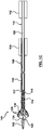
- FIGS 1A-1D are diagrams illustrating a system 100 for delivering a transcatheter prosthetic heart valve to an implantation site according to one embodiment.
- the system 100 includes a shaft assembly 110 and a sheath assembly 106.
- the shaft assembly 110 includes a handle device 112, a carrier shaft 120, a connector shaft 115, a nose cone 102, and a coupling structure 122.
- the connector shaft 115 interconnects the carrier shaft 120 and the nose cone 102, and in some constructions has a reduced-sized diameter to permit placement of a prosthetic heart valve 114 over the connector shaft 115.
- shafts 115 and 120 are independently controllable via the handle device 112.
- the nose cone 102 is disposed at the distal end of the shaft assembly 110.
- a guide wire lumen can be formed through the shafts 115 and 120.
- shaft 115 is a guide wire shaft that defines the guide wire lumen.
- Carrier shaft 120 is sized to be slidably received within the sheath assembly 106, and is configured in the illustrated embodiment for releasable coupling with the prosthetic heart valve 114.
- the carrier shaft 120 forms or includes a coupling device 117.
- the coupling device 117 is configured to selectively retain a proximal portion of the prosthetic heart valve 114.
- the coupling device 117 is configured to releasably mount the prosthetic heart valve 114 to the shaft assembly 110 when the prosthetic heart valve 114 is forced to a collapsed state within the sheath assembly 106. In this collapsed state, then, the prosthetic heart valve 114 will longitudinally move with movement of the shaft assembly 110.
- the sheath assembly 106 is configured to permit deployment of the prosthetic heart valve 114 from the loaded state shown in Figures 1A and 1B .
- the delivery system 100 is configured to transition from the loaded state in which the sheath assembly 106 encompasses the prosthetic heart valve 114 to a deployed state in which the sheath assembly 106 is withdrawn from the prosthetic heart valve 114.
- the coupling structure 122 is disposed near the distal end of the shaft assembly 110.
- the coupling structure 122 is attached (e.g., bonded) to a proximal end of the nose cone 102, and extends proximally from the proximal end of the nose cone 102 toward the prosthetic heart valve 114.
- the coupling structure 122 includes a tubular base portion 124, and a plurality of legs 126 that extend away from the base portion 124.
- the distal end of the prosthetic heart valve 114 is releasably coupled to the legs 126 of the coupling structure 122.
- the coupling structure 126 is configured to move distally and proximally with a corresponding movement of the nose cone 102 to provide a controlled expansion and contraction of the distal end of the prosthetic heart valve 114.
- the coupling structure 122 according to one embodiment provides the controlled expansion or contraction based on longitudinal movement of the distal end of the shaft assembly 110 and the nose cone 102.
- a clinician pushes or pulls the shaft 115 (e.g., via handle device 112), which causes a corresponding longitudinal movement of the nose cone 102, including the coupling structure 122.
- the nose cone 102 can assume a variety of forms, and is generally constructed to facilitate atraumatic placement of the delivery system 100 through a patient's vasculature and heart.
- the handle device 112 is mounted or connected to a proximal end of the carrier shaft 120, and provides a convenient surface for grasping by a clinician.
- the sheath assembly 106 generally includes a sheath 104 and a handle device 108.
- the sheath 104 can be of a conventional catheter-like configuration (e.g., biocompatible polymer with or without an encapsulated wire braiding). In some constructions, the sheath 104 can further incorporate various steering features. Regardless, the sheath 104 is generally compliant, and is able to traverse the tortuous pathways associated with transcatheter heart valve implantation.
- the handle device 108 can assume a wide variety of forms, and is generally mounted or connected to a proximal end of the sheath 104.
- the sheath 104 defines a lumen sized to slidably receive the carrier shaft 120, as well as the prosthetic heart valve 114 in the collapsed state.
- the delivery system 100 is operable to deliver or implant the prosthetic heart valve 114 as described in further detail below.
- Figures 1A and 1B illustrate the system 100 loaded with the prosthetic heart valve 114 prior to deployment.
- the prosthetic heart valve 114 is connected to the carrier shaft 120, for example via the coupling device 117, and is radially constrained within the sheath 104.
- the delivery system 100 is configured to be operable to transition from a loaded state in which the sheath 104 encompasses the prosthetic heart valve 114 to a deployed state in which the sheath 104 is withdrawn from the prosthetic heart valve 114 to permit the prosthetic heart valve 114 to self-expand to a natural arrangement and release from the delivery system 100, as described in further detail below.
- the loaded delivery system 100 is advanced toward the implantation target site, for example in a retrograde manner through a cut-down to the femoral artery and into the patient's descending aorta.
- the delivery system 100 is then advanced, under fluoroscopic guidance, over the aortic arch, through the ascending aorta, and midway across the defective aortic valve (for aortic replacement).
- the sheath 104 is partially retracted relative to the prosthetic heart valve 114 as shown in Figure 1C .
- the handle device 108 provided with the sheath assembly 106 is retracted toward the handle device 112 of the shaft assembly 110.
- a distal region 130 of the prosthetic heart valve 114 is thus exteriorly exposed relative to the sheath 104, and begins to self-expand and self-deploy.
- the self-expansion of the distal region 130 of the prosthetic heart valve 114 is controllably restrained in one embodiment by coupling structure 122.
- the prosthetic heart valve 114 is allowed to gradually self-expand by moving coupling structure 122 in a first longitudinal direction (e.g., in a proximal direction) via the handle device 112.
- FIG. 1C shows the delivery system 100 after the coupling structure 122 has been moved in the proximal direction to provide a controlled expansion of the valve 114.
- This proximal retraction of the sheath 104 and controlled expansion of the prosthetic heart valve 114 continues, with a continually increasing length of the prosthetic heart valve 114 being exposed and thus partially deployed, until the prosthetic heart valve 114 is fully deployed at the native heart valve.
- continued movement of the coupling structure 122 in the first direction causes the legs 126 to eventually slide off the distal end of the prosthetic heart valve 114 and thereby release the valve 114.
- the coupling structure 122 according to one embodiment is configured to be automatically released from the distal end of the prosthetic heart valve 114 when the prosthetic heart valve 114 expands beyond a threshold amount. After deployment, the nose cone 102 and the coupling structure 122 are pulled back through the deployed valve 114, and the delivery system 100 is removed from the patient.
- the position of the prosthetic heart valve 114 relative to the implant site may also be evaluated when it is in a partially deployed state, such as that shown in Figure 1C .
- the clinician believes, based upon the above evaluation, that the prosthetic heart valve 114 should be repositioned relative to the implant site, the prosthetic heart valve 114 is first contracted or "resheathed".
- the resheathing process involves moving coupling structure 122 in a second longitudinal direction (e.g., in a distal direction) opposite the first direction via the handle device 112.
- a second longitudinal direction e.g., in a distal direction
- the coupling structure 122 moves farther away from the prosthetic heart valve 114, resulting in the coupling structure 122 applying more compressive force to the prosthetic heart valve 114, and causing a controlled contraction of the distal end of the valve 114.
- the sheath 104 is then advanced distally relative to the shaft assembly 110, and thus relative to the prosthetic heart valve 114. Distal movement of the sheath 104 continues until the prosthetic heart valve 114 is fully resheathed within the sheath 104.
- FIG. 1D shows the delivery system 100 after the coupling structure 122 has been moved in the distal direction to provide a controlled contraction of the valve 114.
- the delivery system 100 is useful with a variety of different configurations of a stented prosthetic heart valve.
- the prosthetic heart valve 114 includes a stent frame maintaining a valve structure (tissue or synthetic), with the stent frame having a normal, expanded state and collapsible to a collapsed state for loading within the system 100.
- the stent frame can be constructed to self-deploy or self-expand when released from the delivery system 100, or a separate expansion member can be provided (e.g., an expansion balloon).
- the prosthetic heart valve 114 can be a prosthetic sold under the trade name CoreValve® available from Medtronic CoreValve, LLC.
- Other nonlimiting examples of transcatheter heart valve prostheses useful with the system 100 are described in U.S. Publication Nos. 2006/0265056 ; 2007/0239266 ; and 2007/0239269 .
- Figure 2A is a diagram illustrating a top view of one embodiment of the prosthetic heart valve 114 shown in Figures 1B-1D .
- Figure 2B is a diagram illustrating a side view of the prosthetic heart valve 114 shown in Figure 2A according to one embodiment.
- Figure 2C is a diagram illustrating a perspective view of the prosthetic heart valve 114 shown in Figure 2A according to one embodiment.
- Prosthetic heart valve 114 is compressible to a relatively small diameter for percutaneous delivery to the heart of a patient, and is then self-expandable via removal of external compressive forces.
- Prosthetic heart valve 114 according to one embodiment is self-expandable from a compressed arrangement to a natural arrangement
- prosthetic heart valve 114 includes a stent frame 202 and a valve structure 204.
- the stent frame 202 is a self-expanding support structure that includes a number of strut or wire portions 206 arranged relative to each other to provide a desired compressibility and strength to the prosthetic heart valve 114.
- Stent frame 202 can be made from a shape memory material, such as Nitinol.
- Valve structure 204 is mounted inside of the stent frame 202, and includes a plurality of leaflets 208A-208C (collectively referred to as leaflets 208). In the illustrated embodiment, valve structure 204 includes three leaflets 208. In other embodiments, valve structure 204 may include more or less than three leaflets 208.
- Figure 2B also shows a proximal outflow end 210 and a distal inflow end 212 of prosthetic heart valve 114.
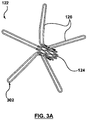
- FIGS 3A and 3B are images illustrating a coupling structure 122 according to one embodiment.
- the coupling structure 122 includes a tubular base portion 124, and a plurality of legs 126 that extend radially away from the base portion 124.
- legs 126 are perpendicular or substantially perpendicular to a longitudinal axis of the tubular base portion 124.
- coupling structure 122 is made from a shape memory material, such as Nitinol.
- Figures 3A and 3B show the coupling structure 122 in its natural state.
- Figure 1B shows the coupling structure 122 in a compressed state with the legs 126 bent toward the tubular base portion 124.
- coupling structure 122 may be formed from a polymer, suture material, or other material.
- Each leg 126 includes an end portion 302 that forms a loop configured to be releasably coupled to a hook on the distal inflow end 212 of the prosthetic heart valve 214, as described in further detail below with reference to Figure 4 .
- the distal end of the prosthetic heart valve 114 is an outflow end, and the coupling structure 122 is releasably coupled to the distal outflow end.
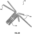
- FIG 4 is an image illustrating a coupling structure 122 releasably coupled to a prosthetic heart valve 114 according to one embodiment.
- Prosthetic heart valve 114 includes hooks 402 formed at the distal inflow end 112 of the valve 114. Each hook 402 is configured to be releasably coupled to one of the legs 126.
- the legs 126 of the coupling structure 122 transition from the compressed state (shown in Figure 1B ), and the angle between each leg 126 and the longitudinal axis of the tubular base portion 124 increases.
- the legs 126 reach an angle that causes the looped end portions 302 of the legs 126 to slide off their corresponding hooks 402, thereby releasing the prosthetic heart valve 114.
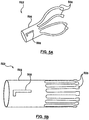
- FIGS 5A and 5B are diagrams illustrating a coupling structure 502 according to an embodiment of the invention.
- the coupling structure 502 is configured to be slidably attached to the nose cone 102, and the coupling structure 502 and the nose cone 102 are configured to slide in a longitudinal direction with respect to each other.
- the coupling structure 502 includes a tubular base portion 504, and a plurality of legs 506 that extend away from the base portion 504.
- the distal end of the prosthetic heart valve 114 is configured to be releasably coupled to the legs 506 of the coupling structure 502.
- coupling structure 502 is made from a shape memory material, such as Nitinol.
- Figure 5A show the coupling structure 502 in its natural state
- Figure 5B shows the coupling structure 502 in a compressed state.
- At least one slot 508 is formed in the tubular base portion 504 of the coupling structure 502.
- a single slot 508 is shown in Figures 5A and 5B , other embodiments may include multiple slots 508. Slot 508 is described in further detail below with reference to Figure 6 .
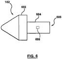
- FIG 6 is a diagram illustrating a nose cone 102 compatible for use with the coupling structure 502 shown in Figures 5A and 5B according to one embodiment of the invention.
- Nose cone 102 includes a tip portion 602 and a tubular portion 604.
- the tubular portion 604 defines a lumen 606, which is configured to slidably receive the coupling structure 502.
- a feature 608 is formed within the lumen 606 on an inner surface of the tubular portion 604.
- Feature 608 is configured to be positioned within the slot 508 of the coupling structure 502, and guides the coupling structure 502 as it slides within the lumen 606.
- the tubular portion 604 When coupling structure 502 is positioned within the tubular portion 604, the tubular portion 604 maintains the coupling structure 502 in the compressed state shown in Figure 5B , which correspondingly compresses the distal end of the prosthetic heart valve 114. As coupling structure 502 slides outside of the tubular portion 604, the coupling structure 502 is allowed to gradually self expand towards its natural state shown in Figure 5A , which correspondingly allows the distal end of the prosthetic heart valve 114 to self expand.
- feature 608 is formed on the outer surface of the tubular portion 604, and coupling structure 502 is configured to longitudinally slide on the outer surface of the tubular portion 604.
- a separate actuator is provided in the delivery system 100 to control the coupling structure 502.
- Coupling structure 502 operates differently than coupling structure 122.
- the prosthetic heart valve 114 is allowed to gradually self-expand by moving nose cone 102 in a first longitudinal direction (e.g., in a distal direction) via the handle device 112.
- the coupling structure 502 begins to slide outside of the lumen 606, resulting in the coupling structure 502 applying less compressive force to the prosthetic heart valve 114 and allowing the distal end of the valve 114 to self-expand.
- Proximal retraction of the sheath 104 and controlled expansion of the prosthetic heart valve 114 continues, with a continually increasing length of the prosthetic heart valve 114 being exposed and thus partially deployed, until the prosthetic heart valve 114 is fully deployed at the native heart valve.
- continued movement of the nose cone 102 in the first direction causes the legs 506 to eventually slide off the distal end of the prosthetic heart valve 114 and thereby release the valve 114.
- the coupling structure 502 according to one embodiment is configured to be automatically released from the distal end of the prosthetic heart valve 114 when the prosthetic heart valve 114 expands beyond a threshold amount. After deployment, the nose cone 102 and the coupling structure 502 are pulled back through the deployed valve 114, and the delivery system 100 is removed from the patient.
- nose cone 102 is moved in a second longitudinal direction (e.g., in a proximal direction) opposite the first direction via the handle device 112.
- the coupling structure 502 begins to slide back inside of the lumen 606, resulting in the coupling structure 502 applying more compressive force to the prosthetic heart valve 114, and causing a controlled contraction of the distal end of the valve 114.
- the sheath 104 is then advanced distally relative to the shaft assembly 110, and thus relative to the prosthetic heart valve 114. Distal movement of the sheath 104 continues until the prosthetic heart valve 114 is fully resheathed within the sheath 104.
- the system 100 can be repositioned relative to the implantation site, and the process repeated until the clinician is comfortable with the achieved positioning.
- the resheathed prosthetic heart valve 114 can be removed from the patient.
- the prosthetic heart valve 114 may also be repositioned without being completely resheathed.
- FIG. 7 is a flow diagram illustrating a method 700 of performing a therapeutic procedure on a defective heart valve of a patient according to one embodiment.
- delivery system 100 is configured to be used to perform method 700.
- a delivery system 100 loaded with a self-expanding prosthetic heart valve 114 having a stent frame 202 to which a valve structure 204 is attached is received, wherein the delivery system 100 includes a shaft assembly 110 slidably positioned within a delivery sheath 104, and wherein the shaft assembly 110 includes a coupling structure 122 or 502 disposed near a distal end of the shaft assembly 110 and coupled to a distal end of the prosthetic heart valve 114, and wherein the delivery sheath 104 contains the prosthetic heart valve 114 in a compressed arrangement.
- the delivery system 100 is manipulated to guide the prosthetic heart valve 114 through the patient's vasculature and into the defective heart valve.
- the delivery sheath 104 is withdrawn from the prosthetic heart valve 114.
- the distal end of the shaft assembly 110 is moved in a first longitudinal direction to cause the coupling structure 122 or 502 to provide a controlled expansion of the distal end of the prosthetic heart valve 114.
- a position of the prosthetic heart valve 114 is evaluated after providing the controlled expansion at 708.
- the distal end of the shaft assembly is moved in a second longitudinal direction to cause the coupling structure 122 or 502 to provide a controlled contraction of the prosthetic heart valve 114 and the delivery sheath 104 is replaced over the prosthetic heart valve 114.
- the delivery system 100 is manipulated to reposition the prosthetic heart valve 114 after providing the controlled contraction at 712.
- the delivery sheath 104 is again withdrawn from the prosthetic heart valve 114.
- the distal end of the shaft assembly 110 is moved in the first longitudinal direction again to cause the coupling structure 122 or 502 to again provide a controlled expansion of the distal end of the prosthetic heart valve 114.
- the prosthetic heart valve 114 is released from the delivery system 100.
Landscapes
- Health & Medical Sciences (AREA)
- Cardiology (AREA)
- Engineering & Computer Science (AREA)
- Biomedical Technology (AREA)
- Heart & Thoracic Surgery (AREA)
- Transplantation (AREA)
- Oral & Maxillofacial Surgery (AREA)
- Vascular Medicine (AREA)
- Life Sciences & Earth Sciences (AREA)
- Animal Behavior & Ethology (AREA)
- General Health & Medical Sciences (AREA)
- Public Health (AREA)
- Veterinary Medicine (AREA)
- Prostheses (AREA)
Description
- This application claims priority under 35 U.S.C. §119(e)(1) to
U.S. Provisional Patent Application Serial No. 61/350,656, filed June 2, 2010 - The present disclosure relates to systems and methods for percutaneous implantation of a heart valve prosthesis. More particularly, it relates to delivery systems and methods for transcatheter implantation of a stented prosthetic heart valve.
- Heart valves, such as the mitral, tricuspid, aortic, and pulmonary valves, are sometimes damaged by disease or by aging, resulting in problems with the proper functioning of the valve. Heart valve problems generally take one of two forms: stenosis in which a valve does not open completely or the opening is too small, resulting in restricted blood flow; or insufficiency in which blood leaks backward across a valve when it should be closed.
- Heart valve replacement has become a routine surgical procedure for patients suffering from valve regurgitation or stenotic calcification of the leaflets. Conventionally, the vast majority of valve replacements entail full sternotomy in placing the patient on cardiopulmonary bypass. Traditional open surgery inflicts significant patient trauma and discomfort, requires extensive recuperation times, and may result in life-threatening complications.
- To address these concerns, within the last decade, efforts have been made to perform cardiac valve replacements using minimally-invasive techniques. In these methods, laparoscopic instruments are employed to make small openings through the patient's ribs to provide access to the heart. While considerable effort has been devoted to such techniques, widespread acceptance has been limited by the clinician's ability to access only certain regions of the heart using laparoscopic instruments.
- Still other efforts have been focused upon percutaneous transcatheter (or transluminal) delivery of replacement cardiac valves to solve the problems presented by traditional open surgery and minimally-invasive surgical methods. In such methods, a valve prosthesis is compacted for delivery in a catheter and then advanced, for example through an opening in the femoral artery and through the descending aorta to the heart, where the prosthesis is then deployed in the valve annulus (e.g., the aortic valve annulus).
- Various types and configurations of prosthetic heart valves are used in percutaneous valve procedures to replace diseased natural human heart valves. The actual shape and configuration of any particular prosthetic heart valve is dependent to some extent upon the valve being replaced (i.e., mitral valve, tricuspid valve, aortic valve, or pulmonary valve). In general, prosthetic heart valve designs attempt to replicate the function of the valve being replaced and thus will include valve leaflet-like structures used with either bioprostheses or mechanical heart valve prostheses. If bioprostheses are selected, the replacement valves may include a valved vein segment or pericardial manufactured tissue valve that is mounted in some manner within an expandable stent frame to make a valved stent. In order to prepare such a valve for percutaneous implantation, one type of valved stent can be initially provided in an expanded or uncrimped condition, then crimped or compressed around a balloon portion of a catheter until it is close to the diameter of the catheter. In other percutaneous implantation systems, the stent frame of the valved stent can be made of a self-expanding material. With these systems, the valved stent is crimped down to a desired size and held in that compressed state with a sheath, for example. Retracting the sheath from this valved stent allows the stent to expand to a larger diameter, such as when the valved stent is in a desired position within a patient. With either of these types of percutaneous stent delivery systems, conventional sewing of the prosthetic heart valve to the patient's native tissue is typically not necessary.
- It is imperative that the stented heart valve prosthesis be accurately located relative to the native annulus prior to full deployment from the catheter. Successful implantation requires that the transcatheter prosthetic heart valve intimately lodge and seal against the native annulus. A self-expanding transcatheter heart valve must have a high radial force when expanding to properly anchor itself in the anatomy of the heart. If the prosthetic is incorrectly positioned relative to the native annulus, serious complications can result as the deployed device will leak and even may dislodge from the implantation site. Greatly complicating this effort is the fact that once the heart valve prosthesis (e.g., a self-deploying stent) is deployed from the catheter, it is exceedingly difficult to re-collapse or "recapture" the prosthetic with conventional delivery tools (e.g., an outer sheath or catheter). This same concern does not arise in the context of other vascular stents; with these procedures, if the target site was "missed," another stent is simply deployed to "make-up" the difference.
- While imaging technology can be employed as part of the implantation procedure to assist a clinician in better evaluating a location of the transcatheter prosthetic heart valve immediately prior to deployment, in many instances, this evaluation alone is insufficient. Instead, clinicians desire the ability to partially deploy the prosthesis and then evaluate a position relative to the native annulus prior to full deployment. While in theory the "re-capturing" of a partially deployed stented prosthetic heart valve is straight forward, in actual practice, the constraints presented by the implantation site and the stented heart valve itself render the technique exceedingly difficult.
-
WO 2010/044874 describes a system and a method for deploying and positioning an endovascular device. - In light of the above, although there have been advances in percutaneous valve replacement techniques and devices, there is a continued desired to provide different delivery systems for delivering and repositioning cardiac replacement valves, and in particular self-expanding stented prosthetic heart valves, to an implantation site in a minimally invasive and percutaneous manner. There is also a continuing desire to be able to provide a more controlled deployment of replacement valves, and to be able to reposition and/or retract the valves once they have been deployed or partially deployed in order to ensure optimal placement of the valves within the patient.
- The invention is defined by the appended claims. Only
figures 5 and6 show embodiments of the invention. One embodiment is directed to a delivery system for use with a prosthetic heart valve having a stent frame to which a valve structure is attached. The system includes a shaft assembly including a distal end and a coupling structure disposed near the distal end and configured to be coupled to a distal end of the prosthetic heart valve. The system includes a sheath assembly defining a lumen sized to slidably receive the shaft assembly. The delivery system is configured to transition from a loaded state in which the sheath assembly encompasses the prosthetic heart valve to a deployed state in which the sheath assembly is withdrawn from the prosthetic heart valve. The coupling structure is configured to provide a controlled expansion or contraction of the distal end of the prosthetic heart valve based on longitudinal movement of the distal end of the shaft assembly. - Another embodiment is directed to a system for performing a therapeutic procedure on a defective heart valve of a patient. The system includes a delivery system including a shaft assembly with a distal end and a coupling structure disposed near the distal end and configured to be coupled to a distal end of the prosthetic heart valve. The delivery system includes a sheath assembly defining a lumen sized to slidably receive the shaft assembly. The system includes a prosthetic heart valve having a stent frame and a valve structure attached to the stent frame and forming at least two valve leaflets. The prosthetic heart valve is self-expandable from a compressed arrangement to a natural arrangement. The delivery system is configured to slidably receive the prosthetic heart valve within the sheath assembly and is configured to be operable to transition from a loaded state in which the sheath assembly encompasses the prosthetic heart valve to a deployed state in which the sheath assembly is withdrawn from the prosthetic heart valve to permit the prosthetic heart valve to self-expand to the natural arrangement and release from the delivery system. The coupling structure is configured to provide a controlled expansion of the distal end of the prosthetic heart valve based on longitudinal movement of the distal end of the shaft assembly in a first direction, and provide a controlled contraction of the distal end of the prosthetic heart valve based on longitudinal movement of the distal end of the shaft assembly in a second direction opposite to the first direction.
- Yet another embodiment is directed to a method of performing a therapeutic procedure on a defective heart valve of a patient. The method includes receiving a delivery system loaded with a self-expanding prosthetic heart valve having a stent frame to which a valve structure is attached. The delivery system includes a shaft assembly slidably positioned within a delivery sheath. The shaft assembly includes a coupling structure disposed near a distal end of the shaft assembly and coupled to a distal end of the prosthetic heart valve. The delivery sheath contains the prosthetic heart valve in a compressed arrangement. The method includes manipulating the delivery system to guide the prosthetic heart valve through the patient's vasculature and into the defective heart valve, and withdrawing the delivery sheath from the prosthetic heart valve. The distal end of the shaft assembly is moved in a first longitudinal direction to cause the coupling structure to provide a controlled expansion of the distal end of the prosthetic heart valve, and the prosthetic heart valve is released from the delivery system.
-
-
Figures 1A-1D are diagrams illustrating a system for delivering a transcatheter prosthetic heart valve to an implantation site according to one embodiment. -
Figures 2A-2C are diagrams illustrating one embodiment of the prosthetic heart valve shown inFigures 1B-1D . -
Figures 3A and3B are images illustrating a coupling structure according to one embodiment. -
Figure 4 is an image illustrating a coupling structure releasably coupled to a prosthetic heart valve according to one embodiment. -
Figures 5A and 5B are diagrams illustrating a coupling structure according to an embodiment of the invention. -
Figure 6 is a diagram illustrating a nose cone compatible for use with the coupling structure shown inFigures 5A and 5B according to one embodiment of the invention. -
Figure 7 is a flow diagram illustrating a method of performing a therapeutic procedure on a heart valve according to one embodiment. - The terms "distal" and "proximal" are used herein with reference to the treating clinician during the use of the catheter system; "Distal" indicates an apparatus portion distant from, or a direction away from the clinician and "proximal" indicates an apparatus portion near to, or a direction towards the clinician. The term "therapy" or "therapeutic procedure" as used herein in the context of heart valves is intended to include the repair of a heart valve, the replacement of a heart valve, or a combination of repair and replacement of a heart valve. While some of the description herein may refer specifically to therapy of aortic valves, the systems and methods disclosed herein can also generally be used for therapy of native or bioprosthetic mitral, pulmonic, or tricuspid valves.
-
Figures 1A-1D are diagrams illustrating asystem 100 for delivering a transcatheter prosthetic heart valve to an implantation site according to one embodiment. In the illustrated embodiment, thesystem 100 includes ashaft assembly 110 and asheath assembly 106. Theshaft assembly 110 includes ahandle device 112, acarrier shaft 120, aconnector shaft 115, anose cone 102, and acoupling structure 122. Theconnector shaft 115 interconnects thecarrier shaft 120 and thenose cone 102, and in some constructions has a reduced-sized diameter to permit placement of aprosthetic heart valve 114 over theconnector shaft 115. In one embodiment,shafts handle device 112. Thenose cone 102 is disposed at the distal end of theshaft assembly 110. Though not shown inFigures 1A-1D , a guide wire lumen can be formed through theshafts shaft 115 is a guide wire shaft that defines the guide wire lumen. -
Carrier shaft 120 is sized to be slidably received within thesheath assembly 106, and is configured in the illustrated embodiment for releasable coupling with theprosthetic heart valve 114. Thecarrier shaft 120 forms or includes acoupling device 117. Thecoupling device 117 is configured to selectively retain a proximal portion of theprosthetic heart valve 114. Thecoupling device 117 is configured to releasably mount theprosthetic heart valve 114 to theshaft assembly 110 when theprosthetic heart valve 114 is forced to a collapsed state within thesheath assembly 106. In this collapsed state, then, theprosthetic heart valve 114 will longitudinally move with movement of theshaft assembly 110. Thesheath assembly 106 is configured to permit deployment of theprosthetic heart valve 114 from the loaded state shown inFigures 1A and1B . Thedelivery system 100 is configured to transition from the loaded state in which thesheath assembly 106 encompasses theprosthetic heart valve 114 to a deployed state in which thesheath assembly 106 is withdrawn from theprosthetic heart valve 114. - The
coupling structure 122 is disposed near the distal end of theshaft assembly 110. Thecoupling structure 122 is attached (e.g., bonded) to a proximal end of thenose cone 102, and extends proximally from the proximal end of thenose cone 102 toward theprosthetic heart valve 114. In the illustrated embodiment, thecoupling structure 122 includes atubular base portion 124, and a plurality oflegs 126 that extend away from thebase portion 124. The distal end of theprosthetic heart valve 114 is releasably coupled to thelegs 126 of thecoupling structure 122. Thecoupling structure 126 is configured to move distally and proximally with a corresponding movement of thenose cone 102 to provide a controlled expansion and contraction of the distal end of theprosthetic heart valve 114. Thus, thecoupling structure 122 according to one embodiment provides the controlled expansion or contraction based on longitudinal movement of the distal end of theshaft assembly 110 and thenose cone 102. In one embodiment, a clinician pushes or pulls the shaft 115 (e.g., via handle device 112), which causes a corresponding longitudinal movement of thenose cone 102, including thecoupling structure 122. - The
nose cone 102 can assume a variety of forms, and is generally constructed to facilitate atraumatic placement of thedelivery system 100 through a patient's vasculature and heart. Thehandle device 112 is mounted or connected to a proximal end of thecarrier shaft 120, and provides a convenient surface for grasping by a clinician. - The
sheath assembly 106 generally includes asheath 104 and ahandle device 108. Thesheath 104 can be of a conventional catheter-like configuration (e.g., biocompatible polymer with or without an encapsulated wire braiding). In some constructions, thesheath 104 can further incorporate various steering features. Regardless, thesheath 104 is generally compliant, and is able to traverse the tortuous pathways associated with transcatheter heart valve implantation. Thehandle device 108 can assume a wide variety of forms, and is generally mounted or connected to a proximal end of thesheath 104. Thesheath 104 defines a lumen sized to slidably receive thecarrier shaft 120, as well as theprosthetic heart valve 114 in the collapsed state. - The
delivery system 100 is operable to deliver or implant theprosthetic heart valve 114 as described in further detail below.Figures 1A and1B illustrate thesystem 100 loaded with theprosthetic heart valve 114 prior to deployment. In particular, theprosthetic heart valve 114 is connected to thecarrier shaft 120, for example via thecoupling device 117, and is radially constrained within thesheath 104. Thedelivery system 100 is configured to be operable to transition from a loaded state in which thesheath 104 encompasses theprosthetic heart valve 114 to a deployed state in which thesheath 104 is withdrawn from theprosthetic heart valve 114 to permit theprosthetic heart valve 114 to self-expand to a natural arrangement and release from thedelivery system 100, as described in further detail below. - The loaded
delivery system 100 is advanced toward the implantation target site, for example in a retrograde manner through a cut-down to the femoral artery and into the patient's descending aorta. Thedelivery system 100 is then advanced, under fluoroscopic guidance, over the aortic arch, through the ascending aorta, and midway across the defective aortic valve (for aortic replacement). After positioning of thedelivery system 100, thesheath 104 is partially retracted relative to theprosthetic heart valve 114 as shown inFigure 1C . For example, thehandle device 108 provided with thesheath assembly 106 is retracted toward thehandle device 112 of theshaft assembly 110. As shown, adistal region 130 of theprosthetic heart valve 114 is thus exteriorly exposed relative to thesheath 104, and begins to self-expand and self-deploy. However, the self-expansion of thedistal region 130 of theprosthetic heart valve 114 is controllably restrained in one embodiment bycoupling structure 122. Theprosthetic heart valve 114 is allowed to gradually self-expand by movingcoupling structure 122 in a first longitudinal direction (e.g., in a proximal direction) via thehandle device 112. As thecoupling structure 122 is moved in the first direction, thecoupling structure 122 moves -closer to theprosthetic heart valve 114, resulting in thecoupling structure 122 applying less compressive force to theprosthetic heart valve 114 and allowing the distal end of thevalve 114 to self-expand.Figure 1C shows thedelivery system 100 after thecoupling structure 122 has been moved in the proximal direction to provide a controlled expansion of thevalve 114. - This proximal retraction of the
sheath 104 and controlled expansion of theprosthetic heart valve 114 continues, with a continually increasing length of theprosthetic heart valve 114 being exposed and thus partially deployed, until theprosthetic heart valve 114 is fully deployed at the native heart valve. In one embodiment, continued movement of thecoupling structure 122 in the first direction causes thelegs 126 to eventually slide off the distal end of theprosthetic heart valve 114 and thereby release thevalve 114. Thus, thecoupling structure 122 according to one embodiment is configured to be automatically released from the distal end of theprosthetic heart valve 114 when theprosthetic heart valve 114 expands beyond a threshold amount. After deployment, thenose cone 102 and thecoupling structure 122 are pulled back through the deployedvalve 114, and thedelivery system 100 is removed from the patient. - Prior to full deployment, the position of the
prosthetic heart valve 114 relative to the implant site may also be evaluated when it is in a partially deployed state, such as that shown inFigure 1C . In the event the clinician believes, based upon the above evaluation, that theprosthetic heart valve 114 should be repositioned relative to the implant site, theprosthetic heart valve 114 is first contracted or "resheathed". - The resheathing process according to one embodiment involves moving
coupling structure 122 in a second longitudinal direction (e.g., in a distal direction) opposite the first direction via thehandle device 112. As thecoupling structure 122 is moved in the second direction, thecoupling structure 122 moves farther away from theprosthetic heart valve 114, resulting in thecoupling structure 122 applying more compressive force to theprosthetic heart valve 114, and causing a controlled contraction of the distal end of thevalve 114. Thesheath 104 is then advanced distally relative to theshaft assembly 110, and thus relative to theprosthetic heart valve 114. Distal movement of thesheath 104 continues until theprosthetic heart valve 114 is fully resheathed within thesheath 104. The controlled contraction of the distal end of theprosthetic heart valve 114 bycoupling structure 122 reduces the force required for the resheathing of thevalve 114.Figure 1D shows thedelivery system 100 after thecoupling structure 122 has been moved in the distal direction to provide a controlled contraction of thevalve 114. Once theprosthetic heart valve 114 is resheathed or recaptured, thesystem 100 can be repositioned relative to the implantation site, and the process repeated until the clinician is comfortable with the achieved positioning. Alternatively, the resheathedprosthetic heart valve 114 can be removed from the patient. Theprosthetic heart valve 114 may also be repositioned without being completely resheathed. - The
delivery system 100 is useful with a variety of different configurations of a stented prosthetic heart valve. In general terms, theprosthetic heart valve 114 includes a stent frame maintaining a valve structure (tissue or synthetic), with the stent frame having a normal, expanded state and collapsible to a collapsed state for loading within thesystem 100. The stent frame can be constructed to self-deploy or self-expand when released from thedelivery system 100, or a separate expansion member can be provided (e.g., an expansion balloon). For example, theprosthetic heart valve 114 can be a prosthetic sold under the trade name CoreValve® available from Medtronic CoreValve, LLC. Other nonlimiting examples of transcatheter heart valve prostheses useful with thesystem 100 are described inU.S. Publication Nos. 2006/0265056 ;2007/0239266 ; and2007/0239269 . -
Figure 2A is a diagram illustrating a top view of one embodiment of theprosthetic heart valve 114 shown inFigures 1B-1D .Figure 2B is a diagram illustrating a side view of theprosthetic heart valve 114 shown inFigure 2A according to one embodiment.Figure 2C is a diagram illustrating a perspective view of theprosthetic heart valve 114 shown inFigure 2A according to one embodiment.Prosthetic heart valve 114 is compressible to a relatively small diameter for percutaneous delivery to the heart of a patient, and is then self-expandable via removal of external compressive forces.Prosthetic heart valve 114 according to one embodiment is self-expandable from a compressed arrangement to a natural arrangement - As shown in
Figures 2A-2C ,prosthetic heart valve 114 includes astent frame 202 and avalve structure 204. Thestent frame 202 is a self-expanding support structure that includes a number of strut orwire portions 206 arranged relative to each other to provide a desired compressibility and strength to theprosthetic heart valve 114.Stent frame 202 can be made from a shape memory material, such as Nitinol.Valve structure 204 is mounted inside of thestent frame 202, and includes a plurality ofleaflets 208A-208C (collectively referred to as leaflets 208). In the illustrated embodiment,valve structure 204 includes three leaflets 208. In other embodiments,valve structure 204 may include more or less than three leaflets 208.Figure 2B also shows aproximal outflow end 210 and adistal inflow end 212 ofprosthetic heart valve 114. -
Figures 3A and3B are images illustrating acoupling structure 122 according to one embodiment. Thecoupling structure 122 includes atubular base portion 124, and a plurality oflegs 126 that extend radially away from thebase portion 124. In the illustrated embodiment,legs 126 are perpendicular or substantially perpendicular to a longitudinal axis of thetubular base portion 124. In one embodiment,coupling structure 122 is made from a shape memory material, such as Nitinol.Figures 3A and3B show thecoupling structure 122 in its natural state. In contrast,Figure 1B shows thecoupling structure 122 in a compressed state with thelegs 126 bent toward thetubular base portion 124. In other embodiments,coupling structure 122 may be formed from a polymer, suture material, or other material. Eachleg 126 includes anend portion 302 that forms a loop configured to be releasably coupled to a hook on thedistal inflow end 212 of the prosthetic heart valve 214, as described in further detail below with reference toFigure 4 . In another embodiment, the distal end of theprosthetic heart valve 114 is an outflow end, and thecoupling structure 122 is releasably coupled to the distal outflow end. -
Figure 4 is an image illustrating acoupling structure 122 releasably coupled to aprosthetic heart valve 114 according to one embodiment.Prosthetic heart valve 114 includeshooks 402 formed at thedistal inflow end 112 of thevalve 114. Eachhook 402 is configured to be releasably coupled to one of thelegs 126. As theprosthetic heart valve 114 expands, thelegs 126 of thecoupling structure 122 transition from the compressed state (shown inFigure 1B ), and the angle between eachleg 126 and the longitudinal axis of thetubular base portion 124 increases. Eventually, thelegs 126 reach an angle that causes the loopedend portions 302 of thelegs 126 to slide off theircorresponding hooks 402, thereby releasing theprosthetic heart valve 114. -
Figures 5A and 5B are diagrams illustrating acoupling structure 502 according to an embodiment of the invention. Thecoupling structure 502 is configured to be slidably attached to thenose cone 102, and thecoupling structure 502 and thenose cone 102 are configured to slide in a longitudinal direction with respect to each other. In the illustrated embodiment, thecoupling structure 502 includes atubular base portion 504, and a plurality oflegs 506 that extend away from thebase portion 504. The distal end of theprosthetic heart valve 114 is configured to be releasably coupled to thelegs 506 of thecoupling structure 502. In one embodiment,coupling structure 502 is made from a shape memory material, such as Nitinol.Figure 5A show thecoupling structure 502 in its natural state, andFigure 5B shows thecoupling structure 502 in a compressed state. At least oneslot 508 is formed in thetubular base portion 504 of thecoupling structure 502. Although asingle slot 508 is shown inFigures 5A and 5B , other embodiments may includemultiple slots 508.Slot 508 is described in further detail below with reference toFigure 6 . -
Figure 6 is a diagram illustrating anose cone 102 compatible for use with thecoupling structure 502 shown inFigures 5A and 5B according to one embodiment of the invention.Nose cone 102 includes atip portion 602 and atubular portion 604. Thetubular portion 604 defines alumen 606, which is configured to slidably receive thecoupling structure 502. Afeature 608 is formed within thelumen 606 on an inner surface of thetubular portion 604.Feature 608 is configured to be positioned within theslot 508 of thecoupling structure 502, and guides thecoupling structure 502 as it slides within thelumen 606. When couplingstructure 502 is positioned within thetubular portion 604, thetubular portion 604 maintains thecoupling structure 502 in the compressed state shown inFigure 5B , which correspondingly compresses the distal end of theprosthetic heart valve 114. Ascoupling structure 502 slides outside of thetubular portion 604, thecoupling structure 502 is allowed to gradually self expand towards its natural state shown inFigure 5A , which correspondingly allows the distal end of theprosthetic heart valve 114 to self expand. In another embodiment, feature 608 is formed on the outer surface of thetubular portion 604, andcoupling structure 502 is configured to longitudinally slide on the outer surface of thetubular portion 604. In one form of this embodiment, a separate actuator is provided in thedelivery system 100 to control thecoupling structure 502. -
Coupling structure 502 according to one embodiment operates differently thancoupling structure 122. Forcoupling structure 502, theprosthetic heart valve 114 is allowed to gradually self-expand by movingnose cone 102 in a first longitudinal direction (e.g., in a distal direction) via thehandle device 112. As thenose cone 102 is moved in the first direction, thecoupling structure 502 begins to slide outside of thelumen 606, resulting in thecoupling structure 502 applying less compressive force to theprosthetic heart valve 114 and allowing the distal end of thevalve 114 to self-expand. Proximal retraction of thesheath 104 and controlled expansion of theprosthetic heart valve 114 continues, with a continually increasing length of theprosthetic heart valve 114 being exposed and thus partially deployed, until theprosthetic heart valve 114 is fully deployed at the native heart valve. In one embodiment, continued movement of thenose cone 102 in the first direction causes thelegs 506 to eventually slide off the distal end of theprosthetic heart valve 114 and thereby release thevalve 114. Thus, thecoupling structure 502 according to one embodiment is configured to be automatically released from the distal end of theprosthetic heart valve 114 when theprosthetic heart valve 114 expands beyond a threshold amount. After deployment, thenose cone 102 and thecoupling structure 502 are pulled back through the deployedvalve 114, and thedelivery system 100 is removed from the patient. - For repositioning,
nose cone 102 is moved in a second longitudinal direction (e.g., in a proximal direction) opposite the first direction via thehandle device 112. As thenose cone 102 is moved in the second direction, thecoupling structure 502 begins to slide back inside of thelumen 606, resulting in thecoupling structure 502 applying more compressive force to theprosthetic heart valve 114, and causing a controlled contraction of the distal end of thevalve 114. Thesheath 104 is then advanced distally relative to theshaft assembly 110, and thus relative to theprosthetic heart valve 114. Distal movement of thesheath 104 continues until theprosthetic heart valve 114 is fully resheathed within thesheath 104. Once theprosthetic heart valve 114 is resheathed or recaptured, thesystem 100 can be repositioned relative to the implantation site, and the process repeated until the clinician is comfortable with the achieved positioning. Alternatively, the resheathedprosthetic heart valve 114 can be removed from the patient. Theprosthetic heart valve 114 may also be repositioned without being completely resheathed. -
Figure 7 is a flow diagram illustrating amethod 700 of performing a therapeutic procedure on a defective heart valve of a patient according to one embodiment. In one embodiment,delivery system 100 is configured to be used to performmethod 700. At 702, adelivery system 100 loaded with a self-expandingprosthetic heart valve 114 having astent frame 202 to which avalve structure 204 is attached is received, wherein thedelivery system 100 includes ashaft assembly 110 slidably positioned within adelivery sheath 104, and wherein theshaft assembly 110 includes acoupling structure shaft assembly 110 and coupled to a distal end of theprosthetic heart valve 114, and wherein thedelivery sheath 104 contains theprosthetic heart valve 114 in a compressed arrangement. - At 704 in
method 700, thedelivery system 100 is manipulated to guide theprosthetic heart valve 114 through the patient's vasculature and into the defective heart valve. At 706, thedelivery sheath 104 is withdrawn from theprosthetic heart valve 114. At 708, the distal end of theshaft assembly 110 is moved in a first longitudinal direction to cause thecoupling structure prosthetic heart valve 114. At 710, a position of theprosthetic heart valve 114 is evaluated after providing the controlled expansion at 708. At 712, the distal end of the shaft assembly is moved in a second longitudinal direction to cause thecoupling structure prosthetic heart valve 114 and thedelivery sheath 104 is replaced over theprosthetic heart valve 114. At 714, thedelivery system 100 is manipulated to reposition theprosthetic heart valve 114 after providing the controlled contraction at 712. At 716, thedelivery sheath 104 is again withdrawn from theprosthetic heart valve 114. At 718, the distal end of theshaft assembly 110 is moved in the first longitudinal direction again to cause thecoupling structure prosthetic heart valve 114. At 720, theprosthetic heart valve 114 is released from thedelivery system 100. - Although the present disclosure has been described with reference to preferred embodiments, workers skilled in the art will recognize that changes can be made in form and detail without departing from the scope of the present disclosure.
Claims (11)
- A delivery system for use with a prosthetic heart valve having a stent frame to which a valve structure is attached, the system comprising:a shaft assembly (110) including a distal end and a nose cone (102) disposed at the distal end, wherein a coupling structure (502) is disposed near the distal end and configured to be coupled to a distal end of the prosthetic heart valve (114);a sheath assembly (106) defining a lumen sized to slidably receive the shaft assembly (110); andwherein the delivery system is configured to transition from a loaded state in which the sheath assembly (110) encompasses the prosthetic heart valve (114) to a deployed state in which the sheath assembly (110) is withdrawn from the prosthetic heart valve (114), and wherein the coupling structure (502) is configured to provide a controlled expansion or contraction of the distal end of the prosthetic heart valve (114) based on longitudinal movement of the distal end of the shaft assembly (110),characterised in that the coupling structure (502) is slidably attached to the nose cone (102), and wherein the coupling structure (502) and the nose cone (102) are configured to slide in a longitudinal direction with respect to each other, wherein the nose cone (102) comprises a tip portion (602) and a tubular portion (604) defining a lumen (606), which is configured to slidably receive the coupling structure (502), wherein the coupling structure (502) comprises a tubular base portion (504) and a plurality of legs (506) extending from the tubular base portion (504), and wherein when the coupling structure (502) is positioned within the tubular portion (604), the tubular portion (604) of the nose cone (102) maintains the coupling structure (502) in the compressed state, which correspondingly compresses the distal end of the prosthetic heart valve (114), wherein the coupling structure (502) can slide outside of the tubular portion (604), which correspondingly allows the distal end of the prosthetic heart valve (114) to self expand.
- The delivery system of claim 1, wherein the coupling structure (502) includes a slot and the nose cone (102) includes a feature configured to be positioned within the slot, wherein the slot and the feature are configured to guide the coupling structure (502) as it slides with respect to the nose cone (102).
- The delivery system of any of claims 1 or 2, wherein the nose cone (102) is configured to be moved in a first direction to cause the coupling structure (502) to provide a controlled expansion of the distal end of the prosthetic heart valve (114), and wherein the nose cone (102) is configured to be moved in a second direction opposite the first direction to cause the coupling structure (502) to provide a controlled contraction of the distal end of the prosthetic heart valve (114).
- The delivery system of claim 3, wherein the first direction is a distal direction and the second direction is a proximal direction.
- The delivery system of claim 1, wherein the coupling structure (122) is configured to be automatically released from the distal end of the prosthetic heart valve (114) when the prosthetic heart valve expands beyond a threshold amount.
- The delivery system of claim 1, wherein the coupling structure (502) is formed from a shape memory material.
- The delivery system of claim 6, wherein the coupling structure (502) is formed from Nitinol, a polymer, or a suture material.
- The delivery system of claim 1, wherein each of the legs (506) includes a looped end portion that is configured to be releasably coupled to a hook on the distal end of the prosthetic heart valve (114).
- The delivery system of claim 1, wherein the distal end of the prosthetic heart valve (114) is an inflow end of the prosthetic heart valve (114).
- The delivery system of claim 1, wherein the distal end of the prosthetic heart valve (114) is an outflow end of the prosthetic heart valve (114).
- A system for performing a therapeutic procedure on a defective heart valve of a patient, the system comprising:a delivery system according to any of the preceding claims; anda prosthetic heart valve (114) having a stent frame and a valve structure attached to the stent frame and forming at least two valve leaflets, the prosthetic heart valve being self-expandable from a compressed arrangement to a natural arrangement;wherein the delivery system is configured to slidably receive the prosthetic heart valve (114) within the sheath assembly (110) and is configured to be operable to transition from a loaded state in which the sheath assembly (110) encompasses the prosthetic heart valve (114) to a deployed state in which the sheath assembly (110) is withdrawn from the prosthetic heart valve (114) to permit the prosthetic heart valve to self-expand to the natural arrangement and release from the delivery system, and wherein the coupling structure (502) is configured to provide a controlled expansion of the distal end of the prosthetic heart valve (114) based on longitudinal movement of the distal end of the shaft assembly (110) in a first direction, and provide a controlled contraction of the distal end of the prosthetic heart valve (114) based on longitudinal movement of the distal end of the shaft assembly (110) in a second direction opposite to the first direction.
Priority Applications (1)
| Application Number | Priority Date | Filing Date | Title |
|---|---|---|---|
| EP19189135.7A EP3590470B1 (en) | 2010-06-02 | 2011-06-01 | Transcatheter delivery system with controlled expansion and contraction of prosthetic heart valve |
Applications Claiming Priority (2)
| Application Number | Priority Date | Filing Date | Title |
|---|---|---|---|
| US35065610P | 2010-06-02 | 2010-06-02 | |
| PCT/US2011/038715 WO2011153210A1 (en) | 2010-06-02 | 2011-06-01 | Transcatheter delivery system and method with controlled expansion and contraction of prosthetic heart vavle |
Related Child Applications (1)
| Application Number | Title | Priority Date | Filing Date |
|---|---|---|---|
| EP19189135.7A Division EP3590470B1 (en) | 2010-06-02 | 2011-06-01 | Transcatheter delivery system with controlled expansion and contraction of prosthetic heart valve |
Publications (2)
| Publication Number | Publication Date |
|---|---|
| EP2575682A1 EP2575682A1 (en) | 2013-04-10 |
| EP2575682B1 true EP2575682B1 (en) | 2019-07-31 |
Family
ID=44454674
Family Applications (2)
| Application Number | Title | Priority Date | Filing Date |
|---|---|---|---|
| EP19189135.7A Active EP3590470B1 (en) | 2010-06-02 | 2011-06-01 | Transcatheter delivery system with controlled expansion and contraction of prosthetic heart valve |
| EP11724908.6A Active EP2575682B1 (en) | 2010-06-02 | 2011-06-01 | Transcatheter delivery system with controlled expansion and contraction of prosthetic heart valve |
Family Applications Before (1)
| Application Number | Title | Priority Date | Filing Date |
|---|---|---|---|
| EP19189135.7A Active EP3590470B1 (en) | 2010-06-02 | 2011-06-01 | Transcatheter delivery system with controlled expansion and contraction of prosthetic heart valve |
Country Status (7)
| Country | Link |
|---|---|
| US (4) | US9561102B2 (en) |
| EP (2) | EP3590470B1 (en) |
| JP (1) | JP5774688B2 (en) |
| CN (1) | CN102917669A (en) |
| AU (1) | AU2011261512B2 (en) |
| BR (1) | BR112012030673A8 (en) |
| WO (1) | WO2011153210A1 (en) |
Cited By (15)
| Publication number | Priority date | Publication date | Assignee | Title |
|---|---|---|---|---|
| US10856984B2 (en) | 2017-08-25 | 2020-12-08 | Neovasc Tiara Inc. | Sequentially deployed transcatheter mitral valve prosthesis |
| US10940001B2 (en) | 2012-05-30 | 2021-03-09 | Neovasc Tiara Inc. | Methods and apparatus for loading a prosthesis onto a delivery system |
| US11311376B2 (en) | 2019-06-20 | 2022-04-26 | Neovase Tiara Inc. | Low profile prosthetic mitral valve |
| US11357622B2 (en) | 2016-01-29 | 2022-06-14 | Neovase Tiara Inc. | Prosthetic valve for avoiding obstruction of outflow |
| US11389291B2 (en) | 2013-04-04 | 2022-07-19 | Neovase Tiara Inc. | Methods and apparatus for delivering a prosthetic valve to a beating heart |
| US11413139B2 (en) | 2011-11-23 | 2022-08-16 | Neovasc Tiara Inc. | Sequentially deployed transcatheter mitral valve prosthesis |
| US11419720B2 (en) | 2010-05-05 | 2022-08-23 | Neovasc Tiara Inc. | Transcatheter mitral valve prosthesis |
| US11464631B2 (en) | 2016-11-21 | 2022-10-11 | Neovasc Tiara Inc. | Methods and systems for rapid retraction of a transcatheter heart valve delivery system |
| US11491006B2 (en) | 2019-04-10 | 2022-11-08 | Neovasc Tiara Inc. | Prosthetic valve with natural blood flow |
| US11497602B2 (en) | 2012-02-14 | 2022-11-15 | Neovasc Tiara Inc. | Methods and apparatus for engaging a valve prosthesis with tissue |
| US11602429B2 (en) | 2019-04-01 | 2023-03-14 | Neovasc Tiara Inc. | Controllably deployable prosthetic valve |
| US11737872B2 (en) | 2018-11-08 | 2023-08-29 | Neovasc Tiara Inc. | Ventricular deployment of a transcatheter mitral valve prosthesis |
| US11779742B2 (en) | 2019-05-20 | 2023-10-10 | Neovasc Tiara Inc. | Introducer with hemostasis mechanism |
| US11998447B2 (en) | 2019-03-08 | 2024-06-04 | Neovasc Tiara Inc. | Retrievable prosthesis delivery system |
| US12109111B2 (en) | 2015-12-15 | 2024-10-08 | Neovasc Tiara Inc. | Transseptal delivery system |
Families Citing this family (132)
| Publication number | Priority date | Publication date | Assignee | Title |
|---|---|---|---|---|
| EP3434225B1 (en) | 2009-06-23 | 2023-11-01 | Endospan Ltd. | Vascular prosthesis for treating aneurysms |
| EP2506810B1 (en) | 2009-11-30 | 2020-07-08 | Endospan Ltd | Multi-component stent-graft system for implantation in a blood vessel with multiple branches |
| US8870950B2 (en) | 2009-12-08 | 2014-10-28 | Mitral Tech Ltd. | Rotation-based anchoring of an implant |
| US20110208289A1 (en) * | 2010-02-25 | 2011-08-25 | Endospan Ltd. | Flexible Stent-Grafts |
| US20110224785A1 (en) | 2010-03-10 | 2011-09-15 | Hacohen Gil | Prosthetic mitral valve with tissue anchors |
| US11653910B2 (en) | 2010-07-21 | 2023-05-23 | Cardiovalve Ltd. | Helical anchor implantation |
| US9132009B2 (en) | 2010-07-21 | 2015-09-15 | Mitraltech Ltd. | Guide wires with commissural anchors to advance a prosthetic valve |
| US9763657B2 (en) | 2010-07-21 | 2017-09-19 | Mitraltech Ltd. | Techniques for percutaneous mitral valve replacement and sealing |
| US8992604B2 (en) | 2010-07-21 | 2015-03-31 | Mitraltech Ltd. | Techniques for percutaneous mitral valve replacement and sealing |
| US9155619B2 (en) | 2011-02-25 | 2015-10-13 | Edwards Lifesciences Corporation | Prosthetic heart valve delivery apparatus |
| WO2012127309A1 (en) | 2011-03-21 | 2012-09-27 | Ontorfano Matteo | Disk-based valve apparatus and method for the treatment of valve dysfunction |
| WO2013003450A1 (en) * | 2011-06-27 | 2013-01-03 | Boston Scientific Scimed, Inc. | Stent delivery systems and methods for making and using stent delivery systems |
| US9254209B2 (en) | 2011-07-07 | 2016-02-09 | Endospan Ltd. | Stent fixation with reduced plastic deformation |
| EP2739214B1 (en) | 2011-08-05 | 2018-10-10 | Cardiovalve Ltd | Percutaneous mitral valve replacement and sealing |
| US20140324164A1 (en) | 2011-08-05 | 2014-10-30 | Mitraltech Ltd. | Techniques for percutaneous mitral valve replacement and sealing |
| WO2013021374A2 (en) | 2011-08-05 | 2013-02-14 | Mitraltech Ltd. | Techniques for percutaneous mitral valve replacement and sealing |
| US8852272B2 (en) | 2011-08-05 | 2014-10-07 | Mitraltech Ltd. | Techniques for percutaneous mitral valve replacement and sealing |
| WO2013030818A2 (en) | 2011-08-28 | 2013-03-07 | Endospan Ltd. | Stent-grafts with post-deployment variable axial and radial displacement |
| US9427339B2 (en) | 2011-10-30 | 2016-08-30 | Endospan Ltd. | Triple-collar stent-graft |
| WO2013084235A2 (en) | 2011-12-04 | 2013-06-13 | Endospan Ltd. | Branched stent-graft system |
| CA3095731C (en) | 2011-12-06 | 2023-02-07 | Aortic Innovations Llc | Device for endovascular aortic repair and method of using the same |
| US9011515B2 (en) | 2012-04-19 | 2015-04-21 | Caisson Interventional, LLC | Heart valve assembly systems and methods |
| US9427315B2 (en) | 2012-04-19 | 2016-08-30 | Caisson Interventional, LLC | Valve replacement systems and methods |
| WO2013171730A1 (en) | 2012-05-15 | 2013-11-21 | Endospan Ltd. | Stent-graft with fixation elements that are radially confined for delivery |
| FR2996748B1 (en) * | 2012-10-12 | 2015-02-06 | Cormove | DEVICE FOR TREATING A BLOOD CIRCULATION CONDUIT |
| US10524909B2 (en) * | 2012-10-12 | 2020-01-07 | St. Jude Medical, Cardiology Division, Inc. | Retaining cage to permit resheathing of a tavi aortic-first transapical system |
| US9993360B2 (en) | 2013-01-08 | 2018-06-12 | Endospan Ltd. | Minimization of stent-graft migration during implantation |
| US20150351906A1 (en) | 2013-01-24 | 2015-12-10 | Mitraltech Ltd. | Ventricularly-anchored prosthetic valves |
| US9675451B2 (en) * | 2013-02-01 | 2017-06-13 | Medtronic CV Luxembourg S.a.r.l. | Anti-paravalvular leakage component for a transcatheter valve prosthesis |
| AU2014213982A1 (en) | 2013-02-06 | 2015-08-13 | Symetis Sa | Prosthetic valve, delivery apparatus and delivery method |
| US11793636B2 (en) | 2013-02-06 | 2023-10-24 | Symetis Sa | Prosthetic valve. delivery apparatus and delivery method |
| US9339385B2 (en) | 2013-03-07 | 2016-05-17 | St. Jude Medical, Cardiology Division, Inc. | Balloon release mechanism for TAVI implant |
| CN105208969B (en) | 2013-03-11 | 2017-10-20 | 恩多斯潘有限公司 | Multicomponent stent-graft system for aortic dissection |
| US9398951B2 (en) | 2013-03-12 | 2016-07-26 | St. Jude Medical, Cardiology Division, Inc. | Self-actuating sealing portions for paravalvular leak protection |
| US9867697B2 (en) | 2013-03-12 | 2018-01-16 | St. Jude Medical, Cardiology Division, Inc. | Self-actuating sealing portions for a paravalvular leak protection |
| US9149278B2 (en) | 2013-03-13 | 2015-10-06 | DePuy Synthes Products, Inc. | Occlusive device delivery system with mechanical detachment |
| US9629739B2 (en) * | 2013-03-13 | 2017-04-25 | DePuy Synthes Products, LLC | Distal capture device for a self-expanding stent |
| US9681951B2 (en) | 2013-03-14 | 2017-06-20 | Edwards Lifesciences Cardiaq Llc | Prosthesis with outer skirt and anchors |
| US9855160B2 (en) * | 2013-03-14 | 2018-01-02 | W. L. Gore & Associates, Inc. | Endoprosthesis delivery systems with deployment aids |
| US9237948B2 (en) * | 2013-07-11 | 2016-01-19 | Medtronic, Inc. | Delivery system with projections |
| US9561103B2 (en) * | 2013-07-17 | 2017-02-07 | Cephea Valve Technologies, Inc. | System and method for cardiac valve repair and replacement |
| US9925045B2 (en) | 2013-10-21 | 2018-03-27 | Medtronic Vascular Galway | Systems, devices and methods for transcatheter valve delivery |
| US9050188B2 (en) | 2013-10-23 | 2015-06-09 | Caisson Interventional, LLC | Methods and systems for heart valve therapy |
| US10603197B2 (en) | 2013-11-19 | 2020-03-31 | Endospan Ltd. | Stent system with radial-expansion locking |
| US9974647B2 (en) | 2014-06-12 | 2018-05-22 | Caisson Interventional, LLC | Two stage anchor and mitral valve assembly |
| EP4066786B1 (en) | 2014-07-30 | 2025-05-14 | Cardiovalve Ltd. | Articulatable prosthetic valve |
| US9750605B2 (en) | 2014-10-23 | 2017-09-05 | Caisson Interventional, LLC | Systems and methods for heart valve therapy |
| US9750607B2 (en) | 2014-10-23 | 2017-09-05 | Caisson Interventional, LLC | Systems and methods for heart valve therapy |
| EP4306080A3 (en) | 2014-12-09 | 2024-04-10 | Cephea Valve Technologies, Inc. | Replacement cardiac valves and method of manufacture |
| BR112017012425A2 (en) | 2014-12-18 | 2018-01-02 | Endospan Ltd | endovascular stent graft with fatigue resistant lateral tube |
| EP3991697B1 (en) | 2015-01-11 | 2024-12-25 | Ascyrus Medical, LLC | Hybrid device for surgical aortic repair |
| CN107427376B (en) * | 2015-01-28 | 2020-09-01 | 俄奥梯科创新有限公司 | Modular internal aortic device and method of use |
| US9974651B2 (en) | 2015-02-05 | 2018-05-22 | Mitral Tech Ltd. | Prosthetic valve with axially-sliding frames |
| ES2978714T3 (en) | 2015-02-05 | 2024-09-18 | Cardiovalve Ltd | Prosthetic valve with axial sliding frames |
| AU2016233216B2 (en) | 2015-03-19 | 2020-08-20 | Caisson Interventional, LLC | Systems and methods for heart valve therapy |
| WO2018136959A1 (en) | 2017-01-23 | 2018-07-26 | Cephea Valve Technologies, Inc. | Replacement mitral valves |
| WO2016183523A1 (en) | 2015-05-14 | 2016-11-17 | Cephea Valve Technologies, Inc. | Cardiac valve delivery devices and systems |
| EP4335415A3 (en) | 2015-05-14 | 2024-05-29 | Cephea Valve Technologies, Inc. | Replacement mitral valves |
| RU2614216C2 (en) * | 2015-08-20 | 2017-03-23 | Федеральное государственное бюджетное учреждение "Сибирский федеральный биомедицинский исследовательский центр имени академика Е.Н. Мешалкина" Министерства здравоохранения Российской Федерации (ФГБУ "СФБМИЦ им. ак. Е.Н. Мешалкина" Минздрава России) | Endovascular delivery system for aortic heart valve prosthesis |
| JP6854282B2 (en) * | 2015-09-18 | 2021-04-07 | テルモ株式会社 | Pressable implant delivery system |
| US10350067B2 (en) * | 2015-10-26 | 2019-07-16 | Edwards Lifesciences Corporation | Implant delivery capsule |
| US10583007B2 (en) | 2015-12-02 | 2020-03-10 | Edwards Lifesciences Corporation | Suture deployment of prosthetic heart valve |
| US10357351B2 (en) | 2015-12-04 | 2019-07-23 | Edwards Lifesciences Corporation | Storage assembly for prosthetic valve |
| AU2016380345B2 (en) | 2015-12-30 | 2021-10-28 | Caisson Interventional, LLC | Systems and methods for heart valve therapy |
| US11833034B2 (en) | 2016-01-13 | 2023-12-05 | Shifamed Holdings, Llc | Prosthetic cardiac valve devices, systems, and methods |
| US10531866B2 (en) | 2016-02-16 | 2020-01-14 | Cardiovalve Ltd. | Techniques for providing a replacement valve and transseptal communication |
| EP3471665B1 (en) | 2016-06-17 | 2023-10-11 | Cephea Valve Technologies, Inc. | Cardiac valve delivery devices |
| US20190231525A1 (en) | 2016-08-01 | 2019-08-01 | Mitraltech Ltd. | Minimally-invasive delivery systems |
| CN114587712B (en) | 2016-08-10 | 2025-08-29 | 卡迪尔维尔福股份有限公司 | Prosthetic valve with coaxial frame |
| USD800908S1 (en) | 2016-08-10 | 2017-10-24 | Mitraltech Ltd. | Prosthetic valve element |
| US11426276B2 (en) | 2016-10-12 | 2022-08-30 | Medtronic Vascular, Inc. | Stented prosthetic heart valve delivery system having an expandable bumper |
| CN106473850B (en) * | 2016-11-02 | 2018-05-01 | 尹先哲 | Complexity esophageal stricture particle stenter to implant device |
| CN108186176B (en) * | 2016-12-08 | 2020-06-30 | 先健科技(深圳)有限公司 | Implant delivery system |
| US10653523B2 (en) | 2017-01-19 | 2020-05-19 | 4C Medical Technologies, Inc. | Systems, methods and devices for delivery systems, methods and devices for implanting prosthetic heart valves |
| AU2018203053B2 (en) | 2017-01-23 | 2020-03-05 | Cephea Valve Technologies, Inc. | Replacement mitral valves |
| US10561495B2 (en) | 2017-01-24 | 2020-02-18 | 4C Medical Technologies, Inc. | Systems, methods and devices for two-step delivery and implantation of prosthetic heart valve |
| US12029647B2 (en) | 2017-03-07 | 2024-07-09 | 4C Medical Technologies, Inc. | Systems, methods and devices for prosthetic heart valve with single valve leaflet |
| US12036113B2 (en) | 2017-06-14 | 2024-07-16 | 4C Medical Technologies, Inc. | Delivery of heart chamber prosthetic valve implant |
| CN109248012B (en) * | 2017-07-14 | 2020-12-25 | 先健科技(深圳)有限公司 | Implant delivery system |
| US12064347B2 (en) | 2017-08-03 | 2024-08-20 | Cardiovalve Ltd. | Prosthetic heart valve |
| US10575948B2 (en) | 2017-08-03 | 2020-03-03 | Cardiovalve Ltd. | Prosthetic heart valve |
| US10537426B2 (en) | 2017-08-03 | 2020-01-21 | Cardiovalve Ltd. | Prosthetic heart valve |
| US11793633B2 (en) | 2017-08-03 | 2023-10-24 | Cardiovalve Ltd. | Prosthetic heart valve |
| US10888421B2 (en) | 2017-09-19 | 2021-01-12 | Cardiovalve Ltd. | Prosthetic heart valve with pouch |
| US11246704B2 (en) | 2017-08-03 | 2022-02-15 | Cardiovalve Ltd. | Prosthetic heart valve |
| US12458493B2 (en) | 2017-09-19 | 2025-11-04 | Cardiovalve Ltd. | Prosthetic heart valve and delivery systems and methods |
| CN214073757U (en) * | 2017-10-24 | 2021-08-31 | 杭州启明医疗器械股份有限公司 | An easy-to-control interventional device delivery device |
| GB201720803D0 (en) | 2017-12-13 | 2018-01-24 | Mitraltech Ltd | Prosthetic Valve and delivery tool therefor |
| GB201800399D0 (en) | 2018-01-10 | 2018-02-21 | Mitraltech Ltd | Temperature-control during crimping of an implant |
| CN110123406B (en) * | 2018-02-02 | 2024-05-17 | 微创神通医疗科技(上海)有限公司 | Implant delivery device |
| WO2019195860A2 (en) | 2018-04-04 | 2019-10-10 | Vdyne, Llc | Devices and methods for anchoring transcatheter heart valve |
| CN110811927A (en) * | 2018-08-09 | 2020-02-21 | 上海微创心通医疗科技有限公司 | Implant loading device |
| CA3279869A1 (en) | 2018-08-21 | 2025-11-29 | Shifamed Holdings Llc | Prosthetic cardiac valve devices, systems, and methods |
| US11857441B2 (en) | 2018-09-04 | 2024-01-02 | 4C Medical Technologies, Inc. | Stent loading device |
| US10321995B1 (en) | 2018-09-20 | 2019-06-18 | Vdyne, Llc | Orthogonally delivered transcatheter heart valve replacement |
| US12186187B2 (en) | 2018-09-20 | 2025-01-07 | Vdyne, Inc. | Transcatheter deliverable prosthetic heart valves and methods of delivery |
| US11278437B2 (en) | 2018-12-08 | 2022-03-22 | Vdyne, Inc. | Compression capable annular frames for side delivery of transcatheter heart valve replacement |
| US11344413B2 (en) | 2018-09-20 | 2022-05-31 | Vdyne, Inc. | Transcatheter deliverable prosthetic heart valves and methods of delivery |
| US11071627B2 (en) | 2018-10-18 | 2021-07-27 | Vdyne, Inc. | Orthogonally delivered transcatheter heart valve frame for valve in valve prosthesis |
| US10595994B1 (en) | 2018-09-20 | 2020-03-24 | Vdyne, Llc | Side-delivered transcatheter heart valve replacement |
| JP7528068B2 (en) | 2018-10-05 | 2024-08-05 | シファメド・ホールディングス・エルエルシー | Prosthetic Heart Valve Devices, Systems, and Methods |
| EP3866900B1 (en) | 2018-10-19 | 2026-01-28 | Shifamed Holdings, LLC | Adjustable medical device |
| US11109969B2 (en) | 2018-10-22 | 2021-09-07 | Vdyne, Inc. | Guidewire delivery of transcatheter heart valve |
| US10653522B1 (en) | 2018-12-20 | 2020-05-19 | Vdyne, Inc. | Proximal tab for side-delivered transcatheter heart valve prosthesis |
| US11253359B2 (en) | 2018-12-20 | 2022-02-22 | Vdyne, Inc. | Proximal tab for side-delivered transcatheter heart valves and methods of delivery |
| WO2020146842A1 (en) | 2019-01-10 | 2020-07-16 | Vdyne, Llc | Anchor hook for side-delivery transcatheter heart valve prosthesis |
| US11185409B2 (en) | 2019-01-26 | 2021-11-30 | Vdyne, Inc. | Collapsible inner flow control component for side-delivered transcatheter heart valve prosthesis |
| US11273032B2 (en) | 2019-01-26 | 2022-03-15 | Vdyne, Inc. | Collapsible inner flow control component for side-deliverable transcatheter heart valve prosthesis |
| US12544226B2 (en) | 2019-02-14 | 2026-02-10 | 4C Medical Technologies, Inc. | Hydrophilic skirt for paravalvular leak mitigation and fit and apposition optimization for prosthetic heart valve implants |
| WO2020181154A2 (en) | 2019-03-05 | 2020-09-10 | Vdyne, Inc. | Tricuspid regurgitation control devices for orthogonal transcatheter heart valve prosthesis |
| US11076956B2 (en) | 2019-03-14 | 2021-08-03 | Vdyne, Inc. | Proximal, distal, and anterior anchoring tabs for side-delivered transcatheter mitral valve prosthesis |
| US10758346B1 (en) | 2019-03-14 | 2020-09-01 | Vdyne, Inc. | A2 clip for side-delivered transcatheter mitral valve prosthesis |
| US10631983B1 (en) | 2019-03-14 | 2020-04-28 | Vdyne, Inc. | Distal subannular anchoring tab for side-delivered transcatheter valve prosthesis |
| US11173027B2 (en) | 2019-03-14 | 2021-11-16 | Vdyne, Inc. | Side-deliverable transcatheter prosthetic valves and methods for delivering and anchoring the same |
| EP4505968A3 (en) | 2019-03-19 | 2025-05-07 | Shifamed Holdings, LLC | Prosthetic cardiac valve devices, systems |
| US11452628B2 (en) | 2019-04-15 | 2022-09-27 | 4C Medical Technologies, Inc. | Loading systems for collapsible prosthetic heart valve devices and methods thereof |
| AU2020267390B2 (en) | 2019-05-04 | 2025-12-04 | Vdyne, Inc. | Cinch device and method for deployment of a side-delivered prosthetic heart valve in a native annulus |
| EP4017442B1 (en) | 2019-08-20 | 2024-10-09 | Vdyne, Inc. | Delivery devices for side-deliverable transcatheter prosthetic valves |
| CA3152632A1 (en) | 2019-08-26 | 2021-03-04 | Vdyne, Inc. | Side-deliverable transcatheter prosthetic valves and methods for delivering and anchoring the same |
| CN112716554B (en) * | 2019-10-28 | 2023-03-24 | 上海佐心医疗科技有限公司 | Medical instrument |
| WO2021086611A1 (en) * | 2019-10-31 | 2021-05-06 | Edwards Lifesciences Corporation | Expandable transition element for a transcatheter delivery device |
| US11234813B2 (en) | 2020-01-17 | 2022-02-01 | Vdyne, Inc. | Ventricular stability elements for side-deliverable prosthetic heart valves and methods of delivery |
| US12133797B2 (en) | 2020-01-31 | 2024-11-05 | 4C Medical Technologies, Inc. | Prosthetic heart valve delivery system: paddle attachment feature |
| US11931253B2 (en) | 2020-01-31 | 2024-03-19 | 4C Medical Technologies, Inc. | Prosthetic heart valve delivery system: ball-slide attachment |
| US12053375B2 (en) | 2020-03-05 | 2024-08-06 | 4C Medical Technologies, Inc. | Prosthetic mitral valve with improved atrial and/or annular apposition and paravalvular leakage mitigation |
| US11992403B2 (en) | 2020-03-06 | 2024-05-28 | 4C Medical Technologies, Inc. | Devices, systems and methods for improving recapture of prosthetic heart valve device with stent frame having valve support with inwardly stent cells |
| EP4203860A4 (en) | 2020-08-31 | 2024-10-09 | Shifamed Holdings, LLC | PROSTHETIC VALVE INTRODUCTION SYSTEM |
| CN114469448A (en) * | 2020-10-23 | 2022-05-13 | 爱德华兹生命科学公司 | Prosthetic valve docking device |
| US12357459B2 (en) | 2020-12-03 | 2025-07-15 | Cardiovalve Ltd. | Transluminal delivery system |
| US12329635B2 (en) | 2020-12-04 | 2025-06-17 | Shifamed Holdings, Llc | Flared prosthetic cardiac valve delivery devices and systems |
| US12201521B2 (en) | 2021-03-22 | 2025-01-21 | Shifamed Holdings, Llc | Anchor position verification for prosthetic cardiac valve devices |
| AU2023204303B1 (en) * | 2023-05-09 | 2023-11-09 | Venus Medtech (Hangzhou) Inc. | Expandable sheath for transcatheter delivery system and delivery system |
Family Cites Families (43)
| Publication number | Priority date | Publication date | Assignee | Title |
|---|---|---|---|---|
| US5693083A (en) * | 1983-12-09 | 1997-12-02 | Endovascular Technologies, Inc. | Thoracic graft and delivery catheter |
| US5480423A (en) * | 1993-05-20 | 1996-01-02 | Boston Scientific Corporation | Prosthesis delivery |
| US5824041A (en) | 1994-06-08 | 1998-10-20 | Medtronic, Inc. | Apparatus and methods for placement and repositioning of intraluminal prostheses |
| US5683451A (en) | 1994-06-08 | 1997-11-04 | Cardiovascular Concepts, Inc. | Apparatus and methods for deployment release of intraluminal prostheses |
| US5702419A (en) | 1994-09-21 | 1997-12-30 | Wake Forest University | Expandable, intraluminal stents |
| US5957949A (en) | 1997-05-01 | 1999-09-28 | World Medical Manufacturing Corp. | Percutaneous placement valve stent |
| US5906619A (en) | 1997-07-24 | 1999-05-25 | Medtronic, Inc. | Disposable delivery device for endoluminal prostheses |
| US7556646B2 (en) * | 2001-09-13 | 2009-07-07 | Edwards Lifesciences Corporation | Methods and apparatuses for deploying minimally-invasive heart valves |
| US8721713B2 (en) | 2002-04-23 | 2014-05-13 | Medtronic, Inc. | System for implanting a replacement valve |
| US7105016B2 (en) | 2002-04-23 | 2006-09-12 | Medtronic Vascular, Inc. | Integrated mechanical handle with quick slide mechanism |
| US8840663B2 (en) | 2003-12-23 | 2014-09-23 | Sadra Medical, Inc. | Repositionable heart valve method |
| US8317859B2 (en) * | 2004-06-28 | 2012-11-27 | J.W. Medical Systems Ltd. | Devices and methods for controlling expandable prostheses during deployment |
| US20050288766A1 (en) * | 2004-06-28 | 2005-12-29 | Xtent, Inc. | Devices and methods for controlling expandable prostheses during deployment |
| US7462191B2 (en) | 2004-06-30 | 2008-12-09 | Edwards Lifesciences Pvt, Inc. | Device and method for assisting in the implantation of a prosthetic valve |
| US20060052867A1 (en) | 2004-09-07 | 2006-03-09 | Medtronic, Inc | Replacement prosthetic heart valve, system and method of implant |
| WO2006073628A1 (en) | 2004-12-01 | 2006-07-13 | Cook Incorporated | Sensing delivery system for intraluminal medical devices |
| DE102005003632A1 (en) | 2005-01-20 | 2006-08-17 | Fraunhofer-Gesellschaft zur Förderung der angewandten Forschung e.V. | Catheter for the transvascular implantation of heart valve prostheses |
| US20060229561A1 (en) | 2005-04-08 | 2006-10-12 | Medtronic Vascular, Inc. | Integrated detachable introducer |
| US7914569B2 (en) | 2005-05-13 | 2011-03-29 | Medtronics Corevalve Llc | Heart valve prosthesis and methods of manufacture and use |
| US7780723B2 (en) | 2005-06-13 | 2010-08-24 | Edwards Lifesciences Corporation | Heart valve delivery system |
| US20080188928A1 (en) | 2005-09-16 | 2008-08-07 | Amr Salahieh | Medical device delivery sheath |
| US8167932B2 (en) * | 2005-10-18 | 2012-05-01 | Edwards Lifesciences Corporation | Heart valve delivery system with valve catheter |
| US20070213813A1 (en) | 2005-12-22 | 2007-09-13 | Symetis Sa | Stent-valves for valve replacement and associated methods and systems for surgery |
| US7740655B2 (en) | 2006-04-06 | 2010-06-22 | Medtronic Vascular, Inc. | Reinforced surgical conduit for implantation of a stented valve therein |
| US20070239269A1 (en) | 2006-04-07 | 2007-10-11 | Medtronic Vascular, Inc. | Stented Valve Having Dull Struts |
| CN101623217B (en) * | 2006-09-07 | 2013-08-21 | 西美蒂斯股份公司 | Stent-valves for valve replacement and associated methods and systems for surgery |
| JP4682259B2 (en) | 2006-09-08 | 2011-05-11 | エドワーズ ライフサイエンシーズ コーポレイション | Integrated heart valve delivery system |
| EP2068764A4 (en) | 2006-09-28 | 2016-07-27 | Heart Leaflet Technologies Inc | Delivery tool for percutaneous delivery of a prosthesis |
| US8470024B2 (en) | 2006-12-19 | 2013-06-25 | Sorin Group Italia S.R.L. | Device for in situ positioning of cardiac valve prosthesis |
| US7814274B2 (en) | 2007-01-19 | 2010-10-12 | Scalent Systems, Inc. | Method and system for dynamic binding in a storage area network |
| BRPI0807261B8 (en) | 2007-02-09 | 2021-06-22 | Taheri Laduca Llc | stent-loaded catheter sets |
| US20080262590A1 (en) * | 2007-04-19 | 2008-10-23 | Medtronic Vascular, Inc. | Delivery System for Stent-Graft |
| EP2150210B1 (en) | 2007-05-15 | 2016-10-12 | JenaValve Technology, Inc. | Handle for manipulating a catheter tip, catheter system and medical insertion system for inserting a self-expandable heart valve stent |
| US20090093876A1 (en) | 2007-08-31 | 2009-04-09 | Edwards Lifesciences Corporation | Recoil inhibitor for prosthetic valve |
| US20090138079A1 (en) | 2007-10-10 | 2009-05-28 | Vector Technologies Ltd. | Prosthetic heart valve for transfemoral delivery |
| WO2009091509A1 (en) | 2008-01-16 | 2009-07-23 | St. Jude Medical, Inc. | Delivery and retrieval systems for collapsible/expandable prosthetic heart valves |
| CA3063001A1 (en) * | 2008-02-29 | 2009-09-03 | Edwards Lifesciences Corporation | Expandable member for deploying a prosthetic device |
| US9061119B2 (en) | 2008-05-09 | 2015-06-23 | Edwards Lifesciences Corporation | Low profile delivery system for transcatheter heart valve |
| US8652202B2 (en) * | 2008-08-22 | 2014-02-18 | Edwards Lifesciences Corporation | Prosthetic heart valve and delivery apparatus |
| EP2349124B1 (en) * | 2008-09-05 | 2018-10-17 | Cook Medical Technologies LLC | Apparatus for improved stent deployment |
| CA2739961A1 (en) | 2008-10-10 | 2010-04-15 | Sadra Medical, Inc. | Medical devices and delivery systems for delivering medical devices |
| US8137398B2 (en) | 2008-10-13 | 2012-03-20 | Medtronic Ventor Technologies Ltd | Prosthetic valve having tapered tip when compressed for delivery |
| EP2341872B1 (en) | 2008-10-17 | 2014-08-06 | Cook Medical Technologies LLC | System for deploying and positioning an endovascular device |
-
2011
- 2011-05-31 US US13/149,160 patent/US9561102B2/en active Active
- 2011-06-01 EP EP19189135.7A patent/EP3590470B1/en active Active
- 2011-06-01 EP EP11724908.6A patent/EP2575682B1/en active Active
- 2011-06-01 AU AU2011261512A patent/AU2011261512B2/en not_active Ceased
- 2011-06-01 JP JP2013513294A patent/JP5774688B2/en not_active Expired - Fee Related
- 2011-06-01 CN CN201180026992XA patent/CN102917669A/en active Pending
- 2011-06-01 BR BR112012030673A patent/BR112012030673A8/en not_active Application Discontinuation
- 2011-06-01 WO PCT/US2011/038715 patent/WO2011153210A1/en not_active Ceased
-
2016
- 2016-12-21 US US15/387,071 patent/US11020223B2/en active Active
-
2021
- 2021-05-24 US US17/327,981 patent/US11833045B2/en active Active
-
2023
- 2023-10-30 US US18/385,338 patent/US12496191B2/en active Active
Non-Patent Citations (1)
| Title |
|---|
| None * |
Cited By (24)
| Publication number | Priority date | Publication date | Assignee | Title |
|---|---|---|---|---|
| US11419720B2 (en) | 2010-05-05 | 2022-08-23 | Neovasc Tiara Inc. | Transcatheter mitral valve prosthesis |
| US11413139B2 (en) | 2011-11-23 | 2022-08-16 | Neovasc Tiara Inc. | Sequentially deployed transcatheter mitral valve prosthesis |
| US12053369B2 (en) | 2011-11-23 | 2024-08-06 | Neovasc Tiara Inc. | Sequentially deployed transcatheter mitral valve prosthesis |
| US12138159B2 (en) | 2012-02-14 | 2024-11-12 | Neovasc Tiara Inc. | Methods and apparatus for engaging a valve prosthesis with tissue |
| US11497602B2 (en) | 2012-02-14 | 2022-11-15 | Neovasc Tiara Inc. | Methods and apparatus for engaging a valve prosthesis with tissue |
| US11617650B2 (en) | 2012-05-30 | 2023-04-04 | Neovasc Tiara Inc. | Methods and apparatus for loading a prosthesis onto a delivery system |
| US11389294B2 (en) | 2012-05-30 | 2022-07-19 | Neovasc Tiara Inc. | Methods and apparatus for loading a prosthesis onto a delivery system |
| US10940001B2 (en) | 2012-05-30 | 2021-03-09 | Neovasc Tiara Inc. | Methods and apparatus for loading a prosthesis onto a delivery system |
| US11389291B2 (en) | 2013-04-04 | 2022-07-19 | Neovase Tiara Inc. | Methods and apparatus for delivering a prosthetic valve to a beating heart |
| US12109111B2 (en) | 2015-12-15 | 2024-10-08 | Neovasc Tiara Inc. | Transseptal delivery system |
| US12193932B2 (en) | 2016-01-29 | 2025-01-14 | Neovasc Tiara Inc. | Prosthetic valve for avoiding obstruction of outflow |
| US11357622B2 (en) | 2016-01-29 | 2022-06-14 | Neovase Tiara Inc. | Prosthetic valve for avoiding obstruction of outflow |
| US11464631B2 (en) | 2016-11-21 | 2022-10-11 | Neovasc Tiara Inc. | Methods and systems for rapid retraction of a transcatheter heart valve delivery system |
| US12201524B2 (en) | 2016-11-21 | 2025-01-21 | Neovasc Tiara Inc. | Methods and systems for rapid retraction of a transcatheter heart valve delivery system |
| US10856984B2 (en) | 2017-08-25 | 2020-12-08 | Neovasc Tiara Inc. | Sequentially deployed transcatheter mitral valve prosthesis |
| US11793640B2 (en) | 2017-08-25 | 2023-10-24 | Neovasc Tiara Inc. | Sequentially deployed transcatheter mitral valve prosthesis |
| US11737872B2 (en) | 2018-11-08 | 2023-08-29 | Neovasc Tiara Inc. | Ventricular deployment of a transcatheter mitral valve prosthesis |
| US11998447B2 (en) | 2019-03-08 | 2024-06-04 | Neovasc Tiara Inc. | Retrievable prosthesis delivery system |
| US11602429B2 (en) | 2019-04-01 | 2023-03-14 | Neovasc Tiara Inc. | Controllably deployable prosthetic valve |
| US12036117B2 (en) | 2019-04-10 | 2024-07-16 | Neovasc Tiara Inc. | Prosthetic valve with natural blood flow |
| US11491006B2 (en) | 2019-04-10 | 2022-11-08 | Neovasc Tiara Inc. | Prosthetic valve with natural blood flow |
| US11779742B2 (en) | 2019-05-20 | 2023-10-10 | Neovasc Tiara Inc. | Introducer with hemostasis mechanism |
| US11311376B2 (en) | 2019-06-20 | 2022-04-26 | Neovase Tiara Inc. | Low profile prosthetic mitral valve |
| US11931254B2 (en) | 2019-06-20 | 2024-03-19 | Neovasc Tiara Inc. | Low profile prosthetic mitral valve |
Also Published As
| Publication number | Publication date |
|---|---|
| EP3590470B1 (en) | 2023-11-15 |
| WO2011153210A1 (en) | 2011-12-08 |
| US9561102B2 (en) | 2017-02-07 |
| US20240058125A1 (en) | 2024-02-22 |
| JP5774688B2 (en) | 2015-09-09 |
| BR112012030673A2 (en) | 2016-09-13 |
| EP3590470A1 (en) | 2020-01-08 |
| EP2575682A1 (en) | 2013-04-10 |
| AU2011261512B2 (en) | 2014-11-27 |
| US20170100246A1 (en) | 2017-04-13 |
| US11020223B2 (en) | 2021-06-01 |
| BR112012030673A8 (en) | 2019-09-17 |
| US20110301702A1 (en) | 2011-12-08 |
| US11833045B2 (en) | 2023-12-05 |
| JP2013527010A (en) | 2013-06-27 |
| CN102917669A (en) | 2013-02-06 |
| US20210275302A1 (en) | 2021-09-09 |
| AU2011261512A1 (en) | 2012-12-20 |
| US12496191B2 (en) | 2025-12-16 |
Similar Documents
| Publication | Publication Date | Title |
|---|---|---|
| US12496191B2 (en) | Transcatheter delivery system and method with controlled expansion and contraction of prosthetic heart valve | |
| EP3603575B1 (en) | Transcatheter prosthetic heart valve delivery system with controlled expansion of prosthetic heart valve | |
| US11666438B2 (en) | Transcatheter prosthetic heart valve delivery system with recapturing feature and method | |
| EP2552355B1 (en) | Transcatheter prosthetic heart valve delivery system with recapturing feature | |
| EP3384879B1 (en) | Delivery systems for prosthetic heart valves | |
| US20090287290A1 (en) | Delivery Systems and Methods of Implantation for Prosthetic Heart Valves |
Legal Events
| Date | Code | Title | Description |
|---|---|---|---|
| PUAI | Public reference made under article 153(3) epc to a published international application that has entered the european phase |
Free format text: ORIGINAL CODE: 0009012 |
|
| 17P | Request for examination filed |
Effective date: 20121219 |
|
| AK | Designated contracting states |
Kind code of ref document: A1 Designated state(s): AL AT BE BG CH CY CZ DE DK EE ES FI FR GB GR HR HU IE IS IT LI LT LU LV MC MK MT NL NO PL PT RO RS SE SI SK SM TR |
|
| DAX | Request for extension of the european patent (deleted) | ||
| 17Q | First examination report despatched |
Effective date: 20151104 |
|
| GRAP | Despatch of communication of intention to grant a patent |
Free format text: ORIGINAL CODE: EPIDOSNIGR1 |
|
| STAA | Information on the status of an ep patent application or granted ep patent |
Free format text: STATUS: GRANT OF PATENT IS INTENDED |
|
| RAP1 | Party data changed (applicant data changed or rights of an application transferred) |
Owner name: MEDTRONIC INC. |
|
| INTG | Intention to grant announced |
Effective date: 20190117 |
|
| GRAS | Grant fee paid |
Free format text: ORIGINAL CODE: EPIDOSNIGR3 |
|
| GRAA | (expected) grant |
Free format text: ORIGINAL CODE: 0009210 |
|
| STAA | Information on the status of an ep patent application or granted ep patent |
Free format text: STATUS: THE PATENT HAS BEEN GRANTED |
|
| AK | Designated contracting states |
Kind code of ref document: B1 Designated state(s): AL AT BE BG CH CY CZ DE DK EE ES FI FR GB GR HR HU IE IS IT LI LT LU LV MC MK MT NL NO PL PT RO RS SE SI SK SM TR |
|
| REG | Reference to a national code |
Ref country code: CH Ref legal event code: EP Ref country code: GB Ref legal event code: FG4D |
|
| REG | Reference to a national code |
Ref country code: AT Ref legal event code: REF Ref document number: 1160138 Country of ref document: AT Kind code of ref document: T Effective date: 20190815 |
|
| REG | Reference to a national code |
Ref country code: IE Ref legal event code: FG4D |
|
| REG | Reference to a national code |
Ref country code: DE Ref legal event code: R096 Ref document number: 602011060863 Country of ref document: DE |
|
| REG | Reference to a national code |
Ref country code: CH Ref legal event code: NV Representative=s name: RENTSCH PARTNER AG, CH |
|
| REG | Reference to a national code |
Ref country code: NL Ref legal event code: FP |
|
| REG | Reference to a national code |
Ref country code: LT Ref legal event code: MG4D |
|
| REG | Reference to a national code |
Ref country code: AT Ref legal event code: MK05 Ref document number: 1160138 Country of ref document: AT Kind code of ref document: T Effective date: 20190731 |
|
| PG25 | Lapsed in a contracting state [announced via postgrant information from national office to epo] |
Ref country code: HR Free format text: LAPSE BECAUSE OF FAILURE TO SUBMIT A TRANSLATION OF THE DESCRIPTION OR TO PAY THE FEE WITHIN THE PRESCRIBED TIME-LIMIT Effective date: 20190731 Ref country code: SE Free format text: LAPSE BECAUSE OF FAILURE TO SUBMIT A TRANSLATION OF THE DESCRIPTION OR TO PAY THE FEE WITHIN THE PRESCRIBED TIME-LIMIT Effective date: 20190731 Ref country code: FI Free format text: LAPSE BECAUSE OF FAILURE TO SUBMIT A TRANSLATION OF THE DESCRIPTION OR TO PAY THE FEE WITHIN THE PRESCRIBED TIME-LIMIT Effective date: 20190731 Ref country code: PT Free format text: LAPSE BECAUSE OF FAILURE TO SUBMIT A TRANSLATION OF THE DESCRIPTION OR TO PAY THE FEE WITHIN THE PRESCRIBED TIME-LIMIT Effective date: 20191202 Ref country code: NO Free format text: LAPSE BECAUSE OF FAILURE TO SUBMIT A TRANSLATION OF THE DESCRIPTION OR TO PAY THE FEE WITHIN THE PRESCRIBED TIME-LIMIT Effective date: 20191031 Ref country code: AT Free format text: LAPSE BECAUSE OF FAILURE TO SUBMIT A TRANSLATION OF THE DESCRIPTION OR TO PAY THE FEE WITHIN THE PRESCRIBED TIME-LIMIT Effective date: 20190731 Ref country code: LT Free format text: LAPSE BECAUSE OF FAILURE TO SUBMIT A TRANSLATION OF THE DESCRIPTION OR TO PAY THE FEE WITHIN THE PRESCRIBED TIME-LIMIT Effective date: 20190731 Ref country code: BG Free format text: LAPSE BECAUSE OF FAILURE TO SUBMIT A TRANSLATION OF THE DESCRIPTION OR TO PAY THE FEE WITHIN THE PRESCRIBED TIME-LIMIT Effective date: 20191031 |
|
| PG25 | Lapsed in a contracting state [announced via postgrant information from national office to epo] |
Ref country code: RS Free format text: LAPSE BECAUSE OF FAILURE TO SUBMIT A TRANSLATION OF THE DESCRIPTION OR TO PAY THE FEE WITHIN THE PRESCRIBED TIME-LIMIT Effective date: 20190731 Ref country code: LV Free format text: LAPSE BECAUSE OF FAILURE TO SUBMIT A TRANSLATION OF THE DESCRIPTION OR TO PAY THE FEE WITHIN THE PRESCRIBED TIME-LIMIT Effective date: 20190731 Ref country code: IS Free format text: LAPSE BECAUSE OF FAILURE TO SUBMIT A TRANSLATION OF THE DESCRIPTION OR TO PAY THE FEE WITHIN THE PRESCRIBED TIME-LIMIT Effective date: 20191130 Ref country code: GR Free format text: LAPSE BECAUSE OF FAILURE TO SUBMIT A TRANSLATION OF THE DESCRIPTION OR TO PAY THE FEE WITHIN THE PRESCRIBED TIME-LIMIT Effective date: 20191101 Ref country code: AL Free format text: LAPSE BECAUSE OF FAILURE TO SUBMIT A TRANSLATION OF THE DESCRIPTION OR TO PAY THE FEE WITHIN THE PRESCRIBED TIME-LIMIT Effective date: 20190731 Ref country code: ES Free format text: LAPSE BECAUSE OF FAILURE TO SUBMIT A TRANSLATION OF THE DESCRIPTION OR TO PAY THE FEE WITHIN THE PRESCRIBED TIME-LIMIT Effective date: 20190731 |
|
| PG25 | Lapsed in a contracting state [announced via postgrant information from national office to epo] |
Ref country code: TR Free format text: LAPSE BECAUSE OF FAILURE TO SUBMIT A TRANSLATION OF THE DESCRIPTION OR TO PAY THE FEE WITHIN THE PRESCRIBED TIME-LIMIT Effective date: 20190731 |
|
| PG25 | Lapsed in a contracting state [announced via postgrant information from national office to epo] |
Ref country code: PL Free format text: LAPSE BECAUSE OF FAILURE TO SUBMIT A TRANSLATION OF THE DESCRIPTION OR TO PAY THE FEE WITHIN THE PRESCRIBED TIME-LIMIT Effective date: 20190731 Ref country code: EE Free format text: LAPSE BECAUSE OF FAILURE TO SUBMIT A TRANSLATION OF THE DESCRIPTION OR TO PAY THE FEE WITHIN THE PRESCRIBED TIME-LIMIT Effective date: 20190731 Ref country code: RO Free format text: LAPSE BECAUSE OF FAILURE TO SUBMIT A TRANSLATION OF THE DESCRIPTION OR TO PAY THE FEE WITHIN THE PRESCRIBED TIME-LIMIT Effective date: 20190731 Ref country code: DK Free format text: LAPSE BECAUSE OF FAILURE TO SUBMIT A TRANSLATION OF THE DESCRIPTION OR TO PAY THE FEE WITHIN THE PRESCRIBED TIME-LIMIT Effective date: 20190731 Ref country code: IT Free format text: LAPSE BECAUSE OF FAILURE TO SUBMIT A TRANSLATION OF THE DESCRIPTION OR TO PAY THE FEE WITHIN THE PRESCRIBED TIME-LIMIT Effective date: 20190731 |
|
| PG25 | Lapsed in a contracting state [announced via postgrant information from national office to epo] |
Ref country code: SM Free format text: LAPSE BECAUSE OF FAILURE TO SUBMIT A TRANSLATION OF THE DESCRIPTION OR TO PAY THE FEE WITHIN THE PRESCRIBED TIME-LIMIT Effective date: 20190731 Ref country code: CZ Free format text: LAPSE BECAUSE OF FAILURE TO SUBMIT A TRANSLATION OF THE DESCRIPTION OR TO PAY THE FEE WITHIN THE PRESCRIBED TIME-LIMIT Effective date: 20190731 Ref country code: SK Free format text: LAPSE BECAUSE OF FAILURE TO SUBMIT A TRANSLATION OF THE DESCRIPTION OR TO PAY THE FEE WITHIN THE PRESCRIBED TIME-LIMIT Effective date: 20190731 Ref country code: IS Free format text: LAPSE BECAUSE OF FAILURE TO SUBMIT A TRANSLATION OF THE DESCRIPTION OR TO PAY THE FEE WITHIN THE PRESCRIBED TIME-LIMIT Effective date: 20200224 |
|
| REG | Reference to a national code |
Ref country code: DE Ref legal event code: R097 Ref document number: 602011060863 Country of ref document: DE |
|
| PLBE | No opposition filed within time limit |
Free format text: ORIGINAL CODE: 0009261 |
|
| STAA | Information on the status of an ep patent application or granted ep patent |
Free format text: STATUS: NO OPPOSITION FILED WITHIN TIME LIMIT |
|
| PG2D | Information on lapse in contracting state deleted |
Ref country code: IS |
|
| PG25 | Lapsed in a contracting state [announced via postgrant information from national office to epo] |
Ref country code: IS Free format text: LAPSE BECAUSE OF FAILURE TO SUBMIT A TRANSLATION OF THE DESCRIPTION OR TO PAY THE FEE WITHIN THE PRESCRIBED TIME-LIMIT Effective date: 20191030 |
|
| PGFP | Annual fee paid to national office [announced via postgrant information from national office to epo] |
Ref country code: CH Payment date: 20200525 Year of fee payment: 10 Ref country code: IE Payment date: 20200521 Year of fee payment: 10 |
|
| 26N | No opposition filed |
Effective date: 20200603 |
|
| PG25 | Lapsed in a contracting state [announced via postgrant information from national office to epo] |
Ref country code: SI Free format text: LAPSE BECAUSE OF FAILURE TO SUBMIT A TRANSLATION OF THE DESCRIPTION OR TO PAY THE FEE WITHIN THE PRESCRIBED TIME-LIMIT Effective date: 20190731 |
|
| PG25 | Lapsed in a contracting state [announced via postgrant information from national office to epo] |
Ref country code: MC Free format text: LAPSE BECAUSE OF FAILURE TO SUBMIT A TRANSLATION OF THE DESCRIPTION OR TO PAY THE FEE WITHIN THE PRESCRIBED TIME-LIMIT Effective date: 20190731 |
|
| GBPC | Gb: european patent ceased through non-payment of renewal fee |
Effective date: 20200601 |
|
| PG25 | Lapsed in a contracting state [announced via postgrant information from national office to epo] |
Ref country code: LU Free format text: LAPSE BECAUSE OF NON-PAYMENT OF DUE FEES Effective date: 20200601 |
|
| REG | Reference to a national code |
Ref country code: BE Ref legal event code: MM Effective date: 20200630 |
|
| PG25 | Lapsed in a contracting state [announced via postgrant information from national office to epo] |
Ref country code: GB Free format text: LAPSE BECAUSE OF NON-PAYMENT OF DUE FEES Effective date: 20200601 |
|
| PG25 | Lapsed in a contracting state [announced via postgrant information from national office to epo] |
Ref country code: BE Free format text: LAPSE BECAUSE OF NON-PAYMENT OF DUE FEES Effective date: 20200630 |
|
| REG | Reference to a national code |
Ref country code: CH Ref legal event code: PL |
|
| PG25 | Lapsed in a contracting state [announced via postgrant information from national office to epo] |
Ref country code: LI Free format text: LAPSE BECAUSE OF NON-PAYMENT OF DUE FEES Effective date: 20210630 Ref country code: IE Free format text: LAPSE BECAUSE OF NON-PAYMENT OF DUE FEES Effective date: 20210601 Ref country code: CH Free format text: LAPSE BECAUSE OF NON-PAYMENT OF DUE FEES Effective date: 20210630 |
|
| PG25 | Lapsed in a contracting state [announced via postgrant information from national office to epo] |
Ref country code: MT Free format text: LAPSE BECAUSE OF FAILURE TO SUBMIT A TRANSLATION OF THE DESCRIPTION OR TO PAY THE FEE WITHIN THE PRESCRIBED TIME-LIMIT Effective date: 20190731 Ref country code: CY Free format text: LAPSE BECAUSE OF FAILURE TO SUBMIT A TRANSLATION OF THE DESCRIPTION OR TO PAY THE FEE WITHIN THE PRESCRIBED TIME-LIMIT Effective date: 20190731 |
|
| PG25 | Lapsed in a contracting state [announced via postgrant information from national office to epo] |
Ref country code: MK Free format text: LAPSE BECAUSE OF FAILURE TO SUBMIT A TRANSLATION OF THE DESCRIPTION OR TO PAY THE FEE WITHIN THE PRESCRIBED TIME-LIMIT Effective date: 20190731 |
|
| PGFP | Annual fee paid to national office [announced via postgrant information from national office to epo] |
Ref country code: NL Payment date: 20250520 Year of fee payment: 15 |
|
| PGFP | Annual fee paid to national office [announced via postgrant information from national office to epo] |
Ref country code: DE Payment date: 20250520 Year of fee payment: 15 |
|
| PGFP | Annual fee paid to national office [announced via postgrant information from national office to epo] |
Ref country code: FR Payment date: 20250520 Year of fee payment: 15 |