EP2575367A2 - Image acquiring device and image acquiring system - Google Patents
Image acquiring device and image acquiring system Download PDFInfo
- Publication number
- EP2575367A2 EP2575367A2 EP12185846A EP12185846A EP2575367A2 EP 2575367 A2 EP2575367 A2 EP 2575367A2 EP 12185846 A EP12185846 A EP 12185846A EP 12185846 A EP12185846 A EP 12185846A EP 2575367 A2 EP2575367 A2 EP 2575367A2
- Authority
- EP
- European Patent Office
- Prior art keywords
- image
- images
- point
- optical spectral
- camera
- Prior art date
- Legal status (The legal status is an assumption and is not a legal conclusion. Google has not performed a legal analysis and makes no representation as to the accuracy of the status listed.)
- Withdrawn
Links
Images


Classifications
-
- H—ELECTRICITY
- H04—ELECTRIC COMMUNICATION TECHNIQUE
- H04N—PICTORIAL COMMUNICATION, e.g. TELEVISION
- H04N13/00—Stereoscopic video systems; Multi-view video systems; Details thereof
- H04N13/20—Image signal generators
- H04N13/296—Synchronisation thereof; Control thereof
-
- G—PHYSICS
- G01—MEASURING; TESTING
- G01C—MEASURING DISTANCES, LEVELS OR BEARINGS; SURVEYING; NAVIGATION; GYROSCOPIC INSTRUMENTS; PHOTOGRAMMETRY OR VIDEOGRAMMETRY
- G01C11/00—Photogrammetry or videogrammetry, e.g. stereogrammetry; Photographic surveying
- G01C11/02—Picture taking arrangements specially adapted for photogrammetry or photographic surveying, e.g. controlling overlapping of pictures
- G01C11/025—Picture taking arrangements specially adapted for photogrammetry or photographic surveying, e.g. controlling overlapping of pictures by scanning the object
-
- G—PHYSICS
- G06—COMPUTING OR CALCULATING; COUNTING
- G06T—IMAGE DATA PROCESSING OR GENERATION, IN GENERAL
- G06T7/00—Image analysis
- G06T7/20—Analysis of motion
- G06T7/246—Analysis of motion using feature-based methods, e.g. the tracking of corners or segments
- G06T7/248—Analysis of motion using feature-based methods, e.g. the tracking of corners or segments involving reference images or patches
-
- G—PHYSICS
- G06—COMPUTING OR CALCULATING; COUNTING
- G06T—IMAGE DATA PROCESSING OR GENERATION, IN GENERAL
- G06T7/00—Image analysis
- G06T7/20—Analysis of motion
- G06T7/285—Analysis of motion using a sequence of stereo image pairs
-
- G—PHYSICS
- G06—COMPUTING OR CALCULATING; COUNTING
- G06T—IMAGE DATA PROCESSING OR GENERATION, IN GENERAL
- G06T7/00—Image analysis
- G06T7/80—Analysis of captured images to determine intrinsic or extrinsic camera parameters, i.e. camera calibration
- G06T7/85—Stereo camera calibration
-
- G—PHYSICS
- G06—COMPUTING OR CALCULATING; COUNTING
- G06V—IMAGE OR VIDEO RECOGNITION OR UNDERSTANDING
- G06V20/00—Scenes; Scene-specific elements
- G06V20/60—Type of objects
- G06V20/64—Three-dimensional [3D] objects
- G06V20/647—Three-dimensional [3D] objects by matching two-dimensional images to three-dimensional objects
-
- H—ELECTRICITY
- H04—ELECTRIC COMMUNICATION TECHNIQUE
- H04N—PICTORIAL COMMUNICATION, e.g. TELEVISION
- H04N13/00—Stereoscopic video systems; Multi-view video systems; Details thereof
- H04N13/20—Image signal generators
- H04N13/204—Image signal generators using stereoscopic image cameras
- H04N13/207—Image signal generators using stereoscopic image cameras using a single two-dimensional [2D] image sensor
- H04N13/221—Image signal generators using stereoscopic image cameras using a single two-dimensional [2D] image sensor using the relative movement between cameras and objects
-
- H—ELECTRICITY
- H04—ELECTRIC COMMUNICATION TECHNIQUE
- H04N—PICTORIAL COMMUNICATION, e.g. TELEVISION
- H04N13/00—Stereoscopic video systems; Multi-view video systems; Details thereof
- H04N13/20—Image signal generators
- H04N13/204—Image signal generators using stereoscopic image cameras
- H04N13/25—Image signal generators using stereoscopic image cameras using two or more image sensors with different characteristics other than in their location or field of view, e.g. having different resolutions or colour pickup characteristics; using image signals from one sensor to control the characteristics of another sensor
-
- H—ELECTRICITY
- H04—ELECTRIC COMMUNICATION TECHNIQUE
- H04N—PICTORIAL COMMUNICATION, e.g. TELEVISION
- H04N13/00—Stereoscopic video systems; Multi-view video systems; Details thereof
- H04N13/20—Image signal generators
- H04N13/257—Colour aspects
-
- B—PERFORMING OPERATIONS; TRANSPORTING
- B64—AIRCRAFT; AVIATION; COSMONAUTICS
- B64U—UNMANNED AERIAL VEHICLES [UAV]; EQUIPMENT THEREFOR
- B64U10/00—Type of UAV
- B64U10/10—Rotorcrafts
- B64U10/13—Flying platforms
- B64U10/14—Flying platforms with four distinct rotor axes, e.g. quadcopters
-
- B—PERFORMING OPERATIONS; TRANSPORTING
- B64—AIRCRAFT; AVIATION; COSMONAUTICS
- B64U—UNMANNED AERIAL VEHICLES [UAV]; EQUIPMENT THEREFOR
- B64U2101/00—UAVs specially adapted for particular uses or applications
- B64U2101/30—UAVs specially adapted for particular uses or applications for imaging, photography or videography
- B64U2101/32—UAVs specially adapted for particular uses or applications for imaging, photography or videography for cartography or topography
-
- B—PERFORMING OPERATIONS; TRANSPORTING
- B64—AIRCRAFT; AVIATION; COSMONAUTICS
- B64U—UNMANNED AERIAL VEHICLES [UAV]; EQUIPMENT THEREFOR
- B64U2201/00—UAVs characterised by their flight controls
- B64U2201/10—UAVs characterised by their flight controls autonomous, i.e. by navigating independently from ground or air stations, e.g. by using inertial navigation systems [INS]
-
- B—PERFORMING OPERATIONS; TRANSPORTING
- B64—AIRCRAFT; AVIATION; COSMONAUTICS
- B64U—UNMANNED AERIAL VEHICLES [UAV]; EQUIPMENT THEREFOR
- B64U2201/00—UAVs characterised by their flight controls
- B64U2201/20—Remote controls
Definitions
- the present invention relates to an image acquiring device and an image acquiring system to obtain an image of an object to be measured and three dimensional data of the object to be measured, and also to acquire optical spectral characteristics for matching the three-dimensional data.
- the three-dimensional data with images as obtained in the conventional type three-dimensional measuring device can be used in map data or the like, and these data have the effects to increase visibility or other effects.
- the data thus obtained are three-dimensional positional data of the object to be measured, and information obtained offers three-dimensional position of the object to be measured.
- an image acquiring device comprises a first camera for acquiring video images, consisting of frame images continuous in time series, a second camera being in a known relation with the first camera and used for acquiring two or more optical spectral images of an object to be measured, and an image pickup control device, and in the image acquiring device, the image pickup control device is configured to extract two or more feature points from one of the frame images, to sequentially specify the feature points in the frame images continuous in time series, to perform image matching between the frame images regarding the frame images corresponding to the two or more optical spectral images based on the feature points, and to synthesize the two or more optical spectral images according to the condition obtained by the image matching.
- the image pickup control device acquires the frame images and the optical spectral images synchronously, and performs relative positioning of each of the optical spectral images based on a position of the feature point on each frame image.
- the image pickup control device extracts at least five feature points from a first frame images of the video images taken by the first camera, specifies the at least five feature points in n-th frame image by image tracking, performs stereo-matching based on the feature points of both images, and prepares a three-dimensional model of the object to be measured.
- the image pickup control device combines information of wavelength components of the synthesized optical spectral images to the three-dimensional model.
- the optical spectral images acquired by the second camera are acquired as two-dimensional images relating to a predetermined wavelength range.
- an image acquiring system comprises a flying object, a GPS device mounted on the flying object, a control device for controlling flight of the flying object, a first camera mounted on the flying object and for acquiring video images made up by frame images continuous to each other in time series, a second camera provided in a known relation with the first camera and for acquiring an optical spectral image of an object to be measured, and an image pickup control device, and in the image acquiring system, the flying object moves from a first point to a second point, the GPS device measures a position of the first point and a position of the second point in geocentric coordinate system, the first camera acquires a still image of the first point, acquires video images during the moving from the first point to the second point, and further, acquires still images at the second point, the second camera acquires two or more optical spectral image in a predetermined wavelength range, the image pickup control device extracts two or more feature points from the still image at the first point, performs video image tracking from the video image during the moving from the first point to
- the second camera acquires two or more optical spectral images in a predetermined wavelength range during the hovering flight at the first point and acquires two or more optical spectral images in the predetermined wavelength range during the hovering flight at the second point
- the image pickup control device synthesizes two or more optical spectral images of the first point, prepares a first optical spectral synthetic image, synthesizes two or more optical spectral images of the second point, prepares a second optical spectral synthetic image, synthesizes the three-dimensional model with at least one of the first optical spectral synthetic image and the second optical spectral synthetic image, and prepares a four-dimensional model having three-dimensional positional data and optical spectral information of the object to be measured.
- the first camera acquires a same position video image in the hovering flight
- the image pickup control device performs synchronization on frame image of the same position video image
- acquires an optical spectral image by the second camera performs image tracking between frame images
- synthesizes the two optical spectral images under the condition obtained by the image matching sequentially repeats the image matching of the frame images and synthesizing of the optical spectral images, and synthesizes all optical spectral images acquired during the hovering flight.
- the second camera acquires two or more optical spectral images in a predetermined wavelength range during the moving from the first point to the second point.
- the image pickup control device performs synchronization of the video image with the frame image, acquires an optical spectral image by the second camera, performs image tracking between the frame images, performs image matching of two frame images corresponding to two optical spectral images continuous in terms of time, synthesizes the two optical images under the condition as obtained in the image matching, sequentially repeats the image matching of the frame image and synthesizing of the optical spectral image, and synthesizes all optical spectral images acquired during the course of the moving.
- an image acquiring device comprises a first camera for acquiring video images, consisting of frame images continuous in time series, a second camera being in a known relation with the first camera and used for acquiring two or more optical spectral images of an object to be measured, and an image pickup control device, and in the image acquiring device, the image pickup control device is configured to extract two or more feature points from one of the frame images, to sequentially specify the feature points in the frame images continuous in time series, to perform image matching between the frame images regarding the frame images corresponding to the two or more optical spectral images based on the feature points, and to synthesize the two or more optical spectral images according to the condition obtained by the image matching.
- the image pickup control device is configured to extract two or more feature points from one of the frame images, to sequentially specify the feature points in the frame images continuous in time series, to perform image matching between the frame images regarding the frame images corresponding to the two or more optical spectral images based on the feature points, and to synthesize the two or more optical spectral images according to the
- the image pickup control device acquires the frame images and the optical spectral images synchronously, and performs relative positioning of each of the optical spectral images based on a position of the feature point on each frame image. As a result, it is possible to make correction in a case where deviation occurs between the optical spectral images and to synthesize optical spectral images with higher accuracy.
- the image pickup control device extracts at least five feature points from a first frame images of the video images taken by the first camera, specifies the at least five feature points in n-th frame image by image tracking, performs stereo-matching based on the feature points of both images, and prepares a three-dimensional model of the object to be measured.
- the image pickup control device extracts at least five feature points from a first frame images of the video images taken by the first camera, specifies the at least five feature points in n-th frame image by image tracking, performs stereo-matching based on the feature points of both images, and prepares a three-dimensional model of the object to be measured.
- the image pickup control device combines information of wavelength components of the synthesized optical spectral images to the three-dimensional model. As a result, it is possible to acquire a four-dimensional image including optical spectral information in addition to the three-dimensional position information.
- an image acquiring system comprises a flying object, a GPS device mounted on the flying object, a control device for controlling flight of the flying object, a first camera mounted on the flying object and for acquiring video images made up by frame images continuous to each other in time series, a second camera provided in a known relation with the first camera and for acquiring an optical spectral image of an object to be measured, and an image pickup control device, and in the image acquiring system, the flying object moves from a first point to a second point, the GPS device measures a position of the first point and a position of the second point in geocentric coordinate system, the first camera acquires a still image of the first point, acquires video images during the moving from the first point to the second point, and further, acquires still images at the second point, the second camera acquires two or more optical spectral image in a predetermined wavelength range, the image pickup control device extracts two or more feature points from the still image at the first point, performs video image tracking from the video image during the moving from the first point
- the second camera acquires two or more optical spectral images in a predetermined wavelength range during the hovering flight at the first point and acquires two or more optical spectral images in the predetermined wavelength range during the hovering flight at the second point
- the image pickup control device synthesizes two or more optical spectral images of the first point, prepares a first optical spectral synthetic image, synthesizes two or more optical spectral images of the second point, prepares a second optical spectral synthetic image, synthesizes the three-dimensional model with at least one of the first optical spectral synthetic image and the second optical spectral synthetic image, and prepares a four-dimensional model having three-dimensional positional data and optical spectral information of the object to be measured.
- the first camera acquires a same position video image in the hovering flight
- the image pickup control device performs synchronization on frame image of the same position video image
- acquires an optical spectral image by the second camera performs image tracking between frame images
- synthesizes the two optical spectral images under the condition obtained by the image matching sequentially repeats the image matching of the frame images and synthesizing of the optical spectral images, and synthesizes all optical spectral images acquired during the hovering flight.
- the second camera acquires two or more optical spectral images in a predetermined wavelength range during the moving from the first point to the second point.
- the second camera acquires two or more optical spectral images in a predetermined wavelength range during the moving from the first point to the second point.
- the image pickup control device performs synchronization of the video image with the frame image, acquires an optical spectral image by the second camera, performs image tracking between the frame images, performs image matching of two frame images corresponding to two optical spectral images continuous in terms of time, synthesizes the two optical images under the condition as obtained in the image matching, sequentially repeats the image matching of the frame image and synthesizing of the optical spectral image, and synthesizes all optical spectral images acquired during the course of the moving.
- two or more optical spectral images acquired by the flying object during the moving it is possible to perform positioning or matching between the optical spectral images via image matching of the frame image, and to prepare an optical spectral synthetic image with high accuracy.
- An image acquiring device of an embodiment of the present invention is mounted on a small Unmanned Aerial Vehicle (UAV), e.g. a small type helicopter which can be operated by remote control operation or can fly autonomously.
- UAV Unmanned Aerial Vehicle
- FIG.1 shows a small flying object 1 where an image acquiring device according to the present embodiment is mounted.
- reference numeral 2 represents a base station control device to be installed on ground surface.
- the base station control device 2 can perform data communication to and from a flying object 1 and the base station control device 2 controls flight of the flying object 1, sets and changes flight plan, and stores and manages information collected by the flying object 1.
- the flying object 1 is a helicopter used as a small type flying object which flies autonomously.
- This helicopter 1 is operated by remote control from the base station control device 2.
- the flight plan is set up on a control device (not shown) of the helicopter 1 from the base station control device 2, and the control device controls navigation means (to be described later) and autonomous flight is performed according to the flight plan.
- the control device controls the navigation means and controls the helicopter 1 at a predetermined speed and at a predetermined altitude, and also can control the helicopter 1 in hovering state (stationary flying condition) at a certain predetermined position.
- the helicopter 1 has a helicopter body 3, and as many propellers as required mounted on the helicopter body 3 (e.g. four sets of propellers 4, 5, 6 and 7, each being mounted at front, rear, left and right positions respectively).
- Each of the propellers 4, 5, 6 and 7 is individually coupled with a motor (not shown), and each of the motors is designed to be controlled independently.
- the propellers 4, 5, 6 and 7 and the motors or the like make up together the navigation means of the helicopter 1.
- a GPS device 9 for measuring a reference position of the helicopter 1 is mounted on the helicopter body 3.
- an image pickup device 11 On the helicopter body 3 of the helicopter 1, an image pickup device 11 is provided on board.
- the image pickup device 11 has an optical axis 12, and the optical axis 12 is designed to be extended in downward direction so that the image pickup device 11 takes image of positions in downward direction of the helicopter 1.
- the image pickup device 11 has a camera unit 13 and an image pickup control device 21.
- the image pickup control device 21 can perform digital photogrammetry of an object to be measured based on image data as acquired by the camera unit 13 and based on position information from the GPS device 9 and performs processing such as synthesizing of optical spectral data acquired by the camera unit 13 with the image data or other types of processing.
- the camera unit 13 comprises an image camera 14 used as a first camera and a spectral camera 15 used as second camera.
- the optical axis 12 is divided by a half-mirror 16.
- the image camera 14 is provided on one optical axis 12a, and the spectral camera 15 is provided on the other optical axis 12b.
- the image camera 14 acquires an image as it is (real image) of an object to be measured, and the spectral camera 15 acquires an optical spectral image.
- the image camera 14 and the spectral camera 15 have the optical axis 12 in common, and the image camera 14 and the spectral camera 15 are in a known relation. Or, the image camera 14 and the spectral camera 15 may be separately provided. Also, the optical axis of the image camera 14 and the optical axis of the spectral camera 15 are set in parallel to each other. A distance between the optical axes is already known, and the image camera 14 and the spectral camera 15 are set in a known relation to each other.
- the image camera 14 takes images at the points to be measured and outputs digital image data.
- the image camera 14 may be a camera to take a still image at a predetermined time interval or may be a video camera to continuously take images.
- the image camera 14 has a CCD or CMOS sensor, which is an aggregate of pixels, as an image pickup element 14a, and a relation between the optical axis 12a and the image pickup element 14a is set in such a manner that the optical axis 12a passes perpendicularly the center (i.e. the center of coordinates of a photodetection surface) of the image pickup element 14a. Therefore, it is so designed that each pixel of the image pickup element 14a can specify the position on the image pickup element 14a, and further that a field angle of each pixel (i.e. an angle with respect to the optical axis 12) can be identified.
- a field angle of each pixel i.e. an angle with respect to the optical axis 12
- the spectral camera 15 has a CCD or CMOS sensor, which is an aggregate of pixels, as an image pickup element 15a, similarly to the case of the image camera 14, and a relation between the optical axis 12b and the image pickup element 15a is set in such a manner that the optical axis 12b passes perpendicularly the center of the image pickup element 15a (i.e. the center of coordinates of photodetection surface). Therefore, each pixel of the image pickup element 15a can identify a position (coordinate) on the image pickup element 15a and a field angle of each pixel (i.e. an angle with respect to the optical axis 12) can be identified. Further, each pixel of the image pickup element 15a and each pixel of the image pickup element 14a match in a one-to-one relation.
- the image pickup control device 21 comprises an arithmetic control unit (CPU) 22, an image data recording unit 23, an image controller 24, a camera control unit 25, a spectral camera controller 26, a spectral data storage unit 27, an image synthesizing unit 28, an image processing unit 29, a characteristics extracting unit 31, a matching unit 32, a measuring unit 33, a model image preparing unit 34, a display unit 35, and a storage unit 36.
- CPU arithmetic control unit
- image data recording unit 23 an image controller 24
- a camera control unit 25 a spectral camera controller 26
- a spectral data storage unit 27 an image synthesizing unit 28
- an image processing unit 29 a characteristics extracting unit 31, a matching unit 32, a measuring unit 33, a model image preparing unit 34, a display unit 35, and a storage unit 36.
- the camera control unit 25 controls the image camera 14 and the spectral camera 15 synchronously.
- the image controller 24 drives the image camera 14 based on an instruction signal from the camera control unit 25 and takes image data (real image data).
- the image data thus acquired are associated with image pickup time and are stored in the image data recording unit 23.
- the spectral camera controller 26 drives the spectral camera 15 according to an instruction from the camera control unit 25 and acquires optical spectral image data.
- the optical spectral image data are associated with time and are stored in the spectral data storage unit 27.
- the image synthesizing unit 28 synthesizes image data stored in the image data recording unit 23 with the optical spectral image data stored in the spectral data storage unit 27, thereby synthesizing a hyper-spectral image in such a manner that all pixels of one image have optical spectral information.
- the image processing unit 29 has the characteristics extracting unit 31 and the matching unit 32, and at least five or more feature points (pass points) can be extracted from image data of one frame. Then, tracking of image or matching of image is performed according to the feature points on the image data different in terms of time or according to the image data acquired from different image pickup points.
- SSDA method for the image tracking and the image matching, SSDA method (sequential similarity detection algorithm), the normalized cross-correlation method, the least square matching method, etc. are used.
- the measuring unit 33 fulfills the functions to execute digital photogrammetry based on two image data acquired by the image camera 14 from different image pickup positions.
- the model image preparing unit 34 is used to associate distance data of each pixel measured by the measuring unit 33 with the hyper-spectral image, and to prepare a model image, which has four-dimensional data, i.e. two-dimensional position data (plane coordinates data) + optical spectral data + height data.
- various types of programs are stored. These programs include: a program needed for camera control, a program needed for synthesis of image data and optical spectral image data, a program needed for image processing, a program needed for measurement, a program needed for preparation of model image, a program for controlling the display unit 35, etc.
- the image data recording unit 23 and the spectral data storage unit 27 may be prepared in a part of the storage unit 36.
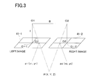
- FIG.3 shows a case that the helicopter 1 flies from a point O1 to a point O2, and that the images are taken at the point O1 and at the point O2.
- a distance B from the point O1 to the point O2 is a photographing base length.
- a numeral 41-1 and a numeral 41-2 each represents an image pickup element 41 of the image pickup device 11 at the point O1 and the point O2 respectively, and the image pickup element 41-1 and 41-2 are equivalent to the image data.
- FIG.3 shows a case that the optical axis 12 of the image pickup device 11 runs in vertical direction, i.e. a case where the helicopter 1 is in horizontal posture.
- a position of a measuring point P on the image as taken at the point O1 i.e. a position on the image pickup element
- a position of the measuring point P on the image as taken at the point O2 i.e. a position on the image pickup element
- Focal length f of the image pickup device 11 and a distance Z from the photographing base length B to the point P, (height distance of the helicopter 1) is determined from relation of similarity of a triangle (O1, O2 and P), a triangle (O1, p1) and a triangle (O2, p2) as:
- Z - Bf / x ⁇ 1 + x ⁇ 2
- ground surface coordinates of the point O1 and the point O2 can be measured by the GPS device 9.
- the photographing base length B is a distance between two points, i.e. a distance between the point O1 and the point O2, and the photographing base length B can be obtained based on the result of measurement by the GPS device 9.
- geocentric positions (plane coordinates) of the measuring point P can be determined similarly from p1 (x1, y1) and p2 (x2, y2) and from the geocentric positions of the point O1 and the point O2 as measured by the GPS device 9.
- an altitude of the helicopter 1 i.e. an altitude from the ground surface
- an altitude distance can be determined at real time (measurement of an altitude distance
- p1 (x1, y1) and p2 (x2, y2) correspond to a point common to a left image 42 taken at the point O1 and a right image 43 taken at the point O2, and P1 and P2 are called as pass points.
- the point p1 in the left image 42 can be obtained as a feature point by image processing such as edge processing or other processing on the left image 42 acquired at the point O1.
- image processing such as edge processing or other processing on the left image 42 acquired at the point O1.
- FIG.4 only one point is shown. Actually, however, a multiple of points are extracted as the feature points.
- a procedure to specify the point p2, which corresponds to the point p1, in the right image 43 is performed by a process called video image tracking.
- the video images are made up by frame images, which are continuous in time series.
- the video images are continuously acquired from the point O1 to the point O2, and a preset range including the point p1 in one frame image is set up in a searching range.
- a searching range within the next frame images, which are adjacent to each other in terms of time, a point to correspond to the point p1 is searched, and further, the point is specified.
- the searching within the preset range with respect to the next frame image and the specifying are repeatedly performed, and the point p2 is finally specified in the right image 43.
- the video image tracking is described in the Japanese Patent Application Publication JP-A-2006-10376 .
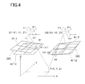
- FIG.4 is a schematical drawing to show condition of an image pickup element 41-1 as taken at the point O1 and tilting condition of an image pickup element 41-2 as taken at the point O2.
- the left image 42 obtained by the image pickup element 41-1 and the right image 43 taken by the image pickup element 41-2 are also in similar conditions.
- the tilting of the image is represented by a rotation angle ⁇ around Z-axis as the center, by a rotation angle ⁇ around a first horizontal axis (X-axis) as the center, and by a rotation angle ⁇ around a second horizontal axis (Y-axis) as the center.
- a rotation angle ⁇ around a first horizontal axis (X-axis) as the center
- a rotation angle ⁇ around a second horizontal axis Y-axis
- rotation angle of each of three axes at the point O1 and the point O2 can be measured by a gyro unit (not shown), and coordinates (x1, y1) of the point p1 in the image at the point O1 and coordinates (x2, y2) of the point p2 in the image at the point O2 can be measured from the positions of pixels of the image pickup element 41. Accordingly, it is assumed here that the coordinates of p1 in a converted coordinate system (model coordinates) after the relative orientation are (X1, Y1, Z1), and the coordinates of p2 in the converted coordinate system (model coordinates) after the relative orientation are (X2, Y2, Z2), and also, that focal length of the image pickup device 11 is f.
- X ⁇ 1 x ⁇ 1 cos ⁇ ⁇ 1 ⁇ cos ⁇ ⁇ 1 - y ⁇ 1 cos ⁇ ⁇ 1 ⁇ sin ⁇ ⁇ 1 - f sin ⁇ ⁇ ⁇ 1
- X 1 x 1 sin ⁇ 1 - y 1 cos ⁇ ⁇ 1
- Z ⁇ 1 x ⁇ 1 sin ⁇ ⁇ 1 ⁇ cos ⁇ ⁇ 1 - y ⁇ 1 sin ⁇ ⁇ 1 ⁇ sin ⁇ ⁇ 1 - f cos ⁇ ⁇ ⁇ 1
- three-dimensional coordinates of the measuring point P can be calculated in the same manner as shown in FIG.3 based on the coordinates (X1, Y1, Z1) of p1 and on the coordinates of p2 (X2, Y2, Z2) (absolute orientation).
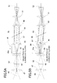
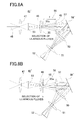
- FIG.5A and FIG.5B each represents an optical system 45 of the spectral camera 15.
- reference numeral 46 represents an optical axis of the optical system 45, and an objective lens 47, a first relay lens 48, a second relay lens 49, a third relay lens 50, an image forming lens 51, and an image pickup element 52 are arranged along the optical axis 46.
- reference numeral 53 represents an image formed by the object lens 47 and a reference symbol f represents a focal length of the second relay lens 49.
- the objective lens 47 and the first relay lens 48 schematically show a first optical system
- the second relay lens 49 schematically shows a second optical system.
- a diaphragm 55 acting as a luminous flux selecting member, is disposed on the side (closer to the second relay lens 49) of the first relay lens 48.
- the diaphragm 55 has a slit-like diaphragm orifice 55a, which is extended in a direction perpendicular to paper surface in the figure.
- the diaphragm 55 is disposed at a focal position of the second relay lens 49 closer to object side or nearly at its focal position, and the diaphragm 55 is supported in such a manner that the diaphragm 55 is movable along a direction perpendicular to the optical axis 46 (i.e. a direction perpendicularly crossing the diaphragm orifice 55a) and that the position of the diaphragm 55 can be changed by an adequate position displacing means such as a linear motor or the like.
- the diaphragm 55 and the second relay lens 49 make up together a tele-centric optical system 56.
- luminous fluxes are split by the tele-centric optical system 56 to a multiple of luminous fluxes (a principal ray 57) running in parallel to each other.
- An interference filter 58 with a transmission type interference film is provided on a converging position of the principal ray 57 (at an image-forming position or at an approximately image-forming position by the second relay lens 49).
- the interference filter 58 fulfills the function as a wavelength selecting filter. From light beams with specific wavelength after passing through the interference filter 58, an image is formed on the image pickup element 52 by the third relay lens 50 and the image-forming lens 51. The image thus formed will be a two-dimensional image formed with the specific wavelength.
- the interference filter 58 has such property that wavelength selecting characteristics are changed according to incident angle of the light beam entering the interference filter 58.
- FIG.6 shows a relation between an incident angle and the peak wavelength of the light, which passes through (i.e. incident angle dependency of the peak wavelength), and by changing the incident angle, it can be known that the peak wavelength is changing.
- the diaphragm orifice 55a of the diaphragm 55 is positioned on the optical axis 46.
- the principal ray 57 runs in parallel to the optical axis 46.
- the diagram 55 is moved as shown in FIG.5B - for instance, in a case where the diagram 55 is moved in upward direction as shown in the figure, the principal ray 57 is tilted with respect to the optical axis 46. That is, incident angle with respect to the interference filter 58 is changed. Therefore, by moving the diaphragm 55, the wavelength of the light passing through the interference filter 58 can be changed.
- FIG.6 when the incident angle with respect to the interference filter 58 is changed, peak of the wavelength of the light passing is changed in the range of 600 nm to 520 nm.
- the interference filter 58 has wavelength selection range W of 600 nm to 520 nm.
- FIG.7 shows wavelength transmission characteristics to match the incident angle to the interference filter 58.
- the interference filter 58 is tilted with respect to the optical axis 46.
- incident angle dependency will be linear from a point where the incident angle exceeds 10°. Accordingly, by tilting the interference filter 58 in advance, the change of the selected wavelength with respect to the displacement of the diaphragm 55 can be effectively obtained.
- the interference filter 58 can be replaced with an interference filter having a different wavelength selection range W'.
- FIG.7 shows an example of optical spectrum, which is obtained when angle of the interference filter 58 is changed to 0°, 10°, 20°, 30° and 40° respectively.
- FIG.8A and FIG.8B each represents a variation example of an optical system 45 as shown in FIG.5A and FIG.5B respectively.
- a transmission type interference filter 58 is used in the optical system 45 shown in FIG.5A and FIG.5B .
- an optical system 45' may be arranged by using a reflection type interference filter 58'.
- the interference filter 58' has a reflection type interference film formed on a reflection mirror. In the optical system 45', wavelength is selected when the light is reflected by the interference filter 58'.
- FIG.8A and FIG.8B the same component as shown in FIG.5A and FIG.5B respectively is referred by the same symbol, and detailed description is not given here.
- the optical system 45' can be set in a compact arrangement.
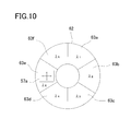
- FIG.9A, FIG.9B and FIG.10 each represents another variation example.
- the variation example shown in each of FIG.9A, FIG.9B and FIG.10 has the same arrangement as the optical system 45' shown in the variation example of FIG.8A and FIG.8B , and a reflection type interference filter 62 is used.
- the interference filter 62 is in shape of a circular disk as shown in FIG.10 , and is rotatably supported via a rotation axis 59.
- reflection surface is equally divided (divided in 6 equal parts in the figure) in circumferential direction. Because the reflection surface is divided, divided reflection surfaces 63a to 63f can be formed as many as required (divided to 6 parts in the figure), and a different reflection interference filter with different wavelength selection characteristics is formed for each of the divided reflection surfaces 63a to 63f.
- a reflection interference film having selection wavelength ⁇ 1 400 nm - 450 nm is formed on the divided reflection surface 63a.
- a reflection interference film having selection wavelength ⁇ 2 of 450 nm to 525 nm is formed on the divided reflection surface 63b
- a reflection interference film having selection wavelength ⁇ 3 of 525 nm - 650 nm is formed on the divided reflection surface 63c
- a reflection interference film having selection wavelength ⁇ 4 of 650 nm - 750 nm is formed on the divided reflection surface 63d
- a reflection interference film having selection wavelength ⁇ 5 of 750 nm - 870 nm is formed on the divided reflection surface 63e
- a reflection interference film having selection wavelength ⁇ 6 of 870 nm - 950 nm is formed on the divided reflection surface 63f.
- An objective lens 47, a first relay lens 48, and a diaphragm 55 are arranged along an optical axis 46.
- a second relay lens 49 is arranged along an optical axis, which runs in parallel to the optical axis 46 and is separated from the optical axis 46 at a predetermined distance, and the interference filter 62 is arranged at a position opposite to the second relay lens 49.
- Luminous fluxes reflected by the interference filter 62 are deflected by a reflection mirror 64, and the luminous fluxes thus deflected pass through an image forming lens 51, and an image is formed on an image pickup element 52.
- reference numeral 57a represents an image formed by a principal ray 57.
- the first relay lens 48 and the diaphragm 55 are at positions deviated from the optical axis 46 of the second relay lens 49, therefore the principal ray 57, which is divided by the tele-centric optical system 56, enters the interference filter 62 in tilted condition. Further, as shown in FIG.9B , when the diaphragm 55 is moved so that the diaphragm 55 is separated from the optical axis 46, the incident angle of the principal ray 57 will be still larger. Therefore, by moving the diaphragm 55, it is possible to change the selected wavelength.
- the divided reflection surface is sequentially changed over from the divided reflection surface 63a to the divided reflection surface 63f.
- the diaphragm 55 is moved for each of the divided reflection surface 63 thus changed over, and an image is acquired with wavelength for each of the position, to which the diaphragm 55 is moved.
- the changeover of the divided reflection surfaces 63a to 63f is performed synchronously with the moving of the diaphragm 55.
- the slit hole returns to a position separated at the most from the position of the optical axis 46 (i.e. reference position), and then the diaphragm 55 is moved for each predetermined amount.
- the wavelength is selected in the range of 400 nm to 950 nm.
- An image is acquired by the image pickup element 52 for each of the selected wavelength, and an optical spectrum can be obtained for total range of 400 nm to 950 nm.
- a divided reflection surface having the corresponding wavelength selection characteristics may be selected and the optical spectrum is obtained.
- the interference filter 62 is designed in form of a circular disk and the interference filter 62 can be rotated, while it may be so arranged that the interference filter 62 is designed in form of a long rectangle, and that the interference filter 62 is divided in longitudinal direction to form the divided reflection surfaces. Then, the interference filter 62 is slid in longitudinal detection and the divided reflection surface may be changed over.
- the disk of a transmission type interference filter 58 is equally divided to a predetermined number of disks, and an interference film having different wavelength characteristics for each divided part is formed. Then, similarly to the variation examples shown in each of FIG.9A, FIG.9B and FIG.10 , the interference filter 58 is rotated and the optical spectral image for each of the divided parts may be acquired.
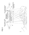
- FIG.11 description will be given below on operation in the present embodiment.
- the following description describes a case where the interference filter is divided, and the site thus divided has different transmission characteristics in an optical system 45 as shown in FIG.5A and FIG.5B or in an optical system 45' shown in FIG.8A, FIG.8B and in FIG.9A and FIG.9B as a spectral camera 15.
- a real image and an optical spectral image are acquired.
- a still image (an left image 42) is acquired at a point O1 by the image camera 14, and the position of point O1 is measured by the GPS device 9.
- the still image acquired is stored in the image data recording unit 23. Further, from the still image at the point O1, at least five feature points (preferably, a multiple number of the feature points) are extracted by the image processing unit 29. When the helicopter 1 is moved from the point O1 to the point O2, tracking by video image is performed on the feature points. Then, a still image (a right image 43) is acquired at the point O2 by the image camera 14. By the GPS device 9, the position of the point O2 is measured.
- the image processing unit 29 at least five of the feature points are specified in the still image at the point O2, and matching is performed on the still image at the point O1 and on the still image at the point O2 according to the feature points. Further, by the measuring unit 33, digital photogrammetry is performed based on the still image acquired at the point O1 and the still image acquired at the point O2.
- an optical spectral image is acquired by the spectral camera 15.
- the helicopter 1 To acquire the optical spectral image, the helicopter 1 is set in stationary state (in hovering state), and the position of the diaphragm 55 is sequentially changed.
- the wavelength to be selected by the interference filter 58 is changed, and an image is acquired for each of the wavelength thus selected.
- the optical spectral image is acquired with a range of wavelength set up in advance.
- the interference filter 58 is rotated, and wavelength characteristics of the site where the principal ray 57 enters are changed. Further, optical spectrum in the wavelength range obtained by the moving of the diaphragm 55 is acquired.
- the optical spectral images acquired as described above are stored in the spectral data storage unit 27.
- an optical spectrum synthesized image including the optical spectral images acquired at the point O1 and at the point O2 in the preset wavelength range ( ⁇ 1 to ⁇ n) can be synthesized. Further, by synthesizing the optical spectral synthesized image at the point O1 and the still image at the point O1, a hyper-spectral images acquired at the point O1 is synthesized. Then, by synthesizing the optical spectrum synthesized image at the point O2 and the still image at the point O2, a hyper-spectral image acquired at the point O2 is synthesized.
- image matching stereo-matching
- image matching is performed on the still image at the point O1 and on the still image at the point O2 based on the feature points. Then, by associating the results of the digital photogrammetry with the still images, an image having three-dimensional positional data (3D model image) can be prepared. Further, at least one of the optical spectral synthetic image at the point O1 and the optical spectral synthetic image at the point O2 is associated with the 3D model image.
- the still image and the optical spectral image correspond to each other in a one-to-one relation, and when one point in the still image is specified, an optical spectrum at the specified point can be immediately acquired from the spectral synthetic image, and three-dimensional positional data can be obtained from the 3D model image.
- the hyper-spectral images can be acquired at the point O1 and at the point O2, and a 3D model image having the optical spectral information, i.e. a 4D model image, can be acquired.
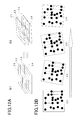
- FIG.12A and FIG.12B each represents a condition where optical spectral images, each having selected wavelength of ⁇ 1, ⁇ 2, ⁇ 3 and ⁇ 4 respectively, are acquired in hovering state.
- Reference symbol S1 in FIG.12A represents a condition where an image pickup device 11 is in completely standstill condition in hovering state
- reference symbol S2 represents a condition where the image pickup device 11 is moving.
- FIG.12B is a drawing where optical spectral images of ⁇ 1, ⁇ 2, ⁇ 3 and ⁇ 4 acquired when the image pickup device 11 are moving are developed according to the course of time.
- black circle represents a feature point extracted.
- FIG.12A and FIG.12B when the images are synthesized as they actually are, the feature points do not concur with each other between the images, and it is seen that error has occurred or the images are blurred.
- the matching is performed so as to be able to synthesize optical spectral images which are acquired for each of the wavelengths in the hovering state.
- the spectral camera 15 even in the operation to take images of the optical spectral images, real images can be acquired at predetermined time interval as set in advance (or in continuous images) by the image camera 14 in synchronization with the spectral camera 15, and the image tracking is carried out.
- Feature points are extracted for each of the frame images, and image tracking is sequentially performed on the feature points for the frame images, which are adjacent to each other in terms of time, and the feature points obtained in a frame image preceding in term of time (hereinafter, referred as "the first frame image”) are specified in a subsequent frame image (hereinafter, referred as "the second frame image”).
- positioning is performed between the preceding frame image and the subsequent frame image. Based on the condition obtained by this positioning, positioning (matching) can be performed for the optical spectral image corresponding to the preceding frame image and a subsequent optical spectral image corresponding to the subsequent frame image.
- the image tracking is carried out continuously for the frame image.
- the feature points are specified to the first frame image, which corresponds to an optical spectral image preceding in terms of time (hereinafter, referred as "the first optical spectral image"). Further, the feature points are specified for the second frame image, which corresponds to the optical spectral image adjacent in terms of time (the second optical spectral image).
- the real image acquired by the image camera 14 and the optical spectral image acquired in synchronization with the real image correspond to each other in a one-to-one relation.
- the condition obtained by the coordinates conversion between the first frame image and the second frame image can be directly applied to the matching of the first optical spectral image and the second optical spectral image.
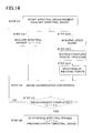
- Step 01 The hovering of the helicopter 1 is started at the point O1, and the left image 42 is acquired by the image camera 14 at the point O1. Also, the measurement of the position of the helicopter 1 (i.e. the position O1) by the GPS device 9 is carried out.
- Step O2 The feature points are extracted by the procedure such as edge processing on the left image 42 acquired.
- Step 03 The video images are acquired by the image camera 14, and the optical spectral images are acquired by the spectral camera 15 in synchronization with the operation of the image camera 14.
- Image tracking at the same position (hereinafter, referred as "the same position tracking") is carried out at the same position by the video images in parallel to the acquisition of the optical spectral images. Based on the result of the video image tracking, image position correcting is performed between each of the optical spectral images.
- Step 21 and Step 221 The optical spectral images in the predetermined wavelength range ( ⁇ 1 to ⁇ n) are acquired for each wavelength in a predetermined time interval.
- the optical spectral images thus acquired are stored in the spectral data storage unit 27 in time series.
- video images (the real images acquired by the image camera 14) are acquired (Step 222).
- the video images are continuously acquired, and the image tracking is carried out between the frame images which constitute the video images.
- Step 223 and Step 224) In the image tracking (the same position tracking), the feature points are extracted from the frame image (the first frame image), which is synchronized in terms of time with the acquisition of the optical spectral image ( ⁇ 1), and the feature points are specified by the image tracking to the subsequent frame image adjacent in terms of time.
- the image tracking is carried out continuously, and the feature points are specified on the frame image (the second frame image) synchronized with the subsequent optical spectral image ( ⁇ 2), which are adjacent in terms of time.
- Step 23 Based on the feature points of the first frame image thus acquired and on the feature points of the second frame image, the matching is performed between the first frame image and the second frame image, and the coordinates conversion is performed between the first frame image and the second frame image is carried out.
- the image camera 14 and the spectral camera 15 acquire the images on the same axis.
- Each pixel of the frame image and each pixel of the optical spectral images correspond to each other in a one-to-one relation, and the condition of the matching of the frame images and the conditions of coordinates conversion can also be applied to the optical spectral images, which are adjacent to each other in terms of time.
- Step 24 It is judged whether all spectral images with all wavelengths are acquired or not. If all spectral images are not acquired, it is returned to Step 221 and Step 222, and the acquisition of the optical spectral image and the same position tracking are carried out continuously.
- Step 25 When the optical spectral images for all wavelengths of a predetermined wavelength range ( ⁇ 1 to ⁇ n) have been acquired, all optical spectral images are synthesized under the condition obtained by the video image tracking and the optical spectral synthesized images having optical spectra in the predetermined wavelength range ( ⁇ 1 to ⁇ n) at the point O1 can be acquired. Further, by synthesizing the optical spectral synthesized image with the still images, the hyper-spectral image can be acquired.
- Step 04 to Step 06 When the still image and the hyper-spectral image at the point O1 have been acquired, the helicopter 1 is moved to the point O2. During the moving, the video image is acquired by the image camera 14, and the image tracking (moving tracking) is performed. The moving tracking may be carried out based on the feature points extracted at the left image 42 or the moving tracking may be carried out by using the feature points finally obtained by the same position tracking in hovering state.
- Step 07 When the helicopter 1 reaches the point O2, the moving tracking is completed. The hovering is started, and the right image 43 is acquired.
- Step 08 In the hovering state, while acquiring the video images by the image camera 14, the optical spectral image is acquired by the spectral camera 15 in synchronization with the image camera 14.
- the image tracking at the same position (the same position tracking) by the video image is executed at the same time as acquiring of the optical spectral image, and correction of the image position between the optical spectral images is carried out based on the result of the same position tracking.
- Step 21 to Step 25 The procedures of Step 21 to Step 25 are carried out, and optical spectral images for all wavelengths of the predetermined wavelength range ( ⁇ 1 to ⁇ n) at the point O2 are acquired and the optical spectral synthesized images having optical spectra in the predetermined wavelength range ( ⁇ 1 to ⁇ n) at the point O2 are acquired by synthesizing all optical spectral image thus obtained. Further, by synthesizing the optical spectral synthesized images with the right image 43, the hyper-spectral image is acquired.
- Step 09, Step 10 and Step 11 Based on the feature points specified in the right image 43 and on the feature points specified in the left image 42, matching is performed. Also, coordinates conversion (relative orientation) with one of the left image 42 or the right image 43 as reference is conducted. Further, the coordinates conversion (absolute orientation) to the geocentric coordinates is carried out based on a result of measurement at the point O1 and O2 by the GPS device 9.
- Step 12 and Step 13 Based on the result of the absolute orientation, stereo-matching of the left image 42 and the right image 43 is conducted, and a topographical 3D model having three-dimensional positional data is obtained.
- Step 14 As described above, since the optical spectral image and the still image correspond to each other in a one-to-one relation, the three-dimensional positional data are acquired at a position where the optical spectra are obtained. By synthesizing the optical spectral image with the 3D model, a four-dimensional model having the topographical three-dimensional positional data and the optical spectral information can be prepared.
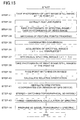
- the left image 42 is acquired at the point O1. At least five of the feature points are extracted by the procedure such as edge processing of the left image 42 or other processing. Further, the video images are continuously acquired by the image camera 14, and the feature points are specified in the frame images, which constitute the video images. Then, in synchronization with the acquisition of the video images, in synchronization with each frame image, or in synchronization with the frame images acquired at two or more time intervals, optical spectral images can be acquired by the spectral camera 15.
- the image matching is carried out based on the feature points. Based on the result of the image matching, matching of the optical spectral images corresponding to the frame images is conducted.
- the sequential matching is performed based on the result of the matching of the video images which are acquired at the same time as the optical spectral images.
- the optical spectral images are acquired in the intended wavelength range up to the wavelengths ( ⁇ 1 to ⁇ n) until the helicopter reaches the point O2 from the point O1.
- the synthesis of the optical spectral images is carried out in a manner similar to the procedures in Step 21 to Step 25 in the first embodiment.
- the helicopter 1 When the helicopter 1 reaches the point O2, the right image 43 is acquired by the image camera 14, and the feature points extracted in the left image 42 are specified in the right image 43. To specify the feature points in the right image 43, the results of the image tracking sequentially between the frame images during the moving should be reflected.
- Step 39, Step 40 and Step 41 Based on the feature points specified in the right image 43 and also on the feature points specified in the left image 42, the matching is performed. Relative orientation is carried out either the left image 42 or the right image 43 as reference. Further, absolute orientation is conducted to the geocentric coordinates system based on the result of measurement of the GPS device 9.
- Step 42 and Step 43 Based on the result of the absolute orientation, stereo-matching is performed between the left image 42 and the right image 43, and a topographical 3D model having the three-dimensional positional data is obtained.
- Step 44 Further, by synthesizing the optical spectral image with the 3D model, a four-dimensional model having topographical three-dimensional positional data and the optical spectral information can be prepared.
- the hovering process is omitted and that the optical spectral images in the hovering process are acquired during the moving of the helicopter 1.
- the optical spectral images are acquired in the desired wavelength, while the other spectral camera can be adopted for the purpose.
- images may be acquired along a line, which goes across a field of view of the camera, and the optical spectral image may be acquired in such a manner that images may be acquired by resolving the images along the line thus obtained to the optical spectra by using diffraction grating and by scanning the line over the total field of view of the camera.
Landscapes
- Engineering & Computer Science (AREA)
- Multimedia (AREA)
- Physics & Mathematics (AREA)
- General Physics & Mathematics (AREA)
- Signal Processing (AREA)
- Theoretical Computer Science (AREA)
- Computer Vision & Pattern Recognition (AREA)
- Radar, Positioning & Navigation (AREA)
- Remote Sensing (AREA)
- Length Measuring Devices By Optical Means (AREA)
- Aviation & Aerospace Engineering (AREA)
- Image Analysis (AREA)
- Spectrometry And Color Measurement (AREA)
- Investigating Or Analysing Materials By Optical Means (AREA)
- Image Processing (AREA)
Abstract
Description
- The present invention relates to an image acquiring device and an image acquiring system to obtain an image of an object to be measured and three dimensional data of the object to be measured, and also to acquire optical spectral characteristics for matching the three-dimensional data.
- In the past, it has been practiced to obtain an image of an object to be measured at the same time as the acquisition of the three-dimensional data of the object to be measured by carrying out digital photogrammetry etc. of the object to be measured and to acquire three-dimensional data with the images.
- The three-dimensional data with images as obtained in the conventional type three-dimensional measuring device can be used in map data or the like, and these data have the effects to increase visibility or other effects.
- On the other hand, the data thus obtained are three-dimensional positional data of the object to be measured, and information obtained offers three-dimensional position of the object to be measured.
- When measurement is performed on the object to be measured, it is desirable that more information can be obtained, and it is desirable that - not only positional information of the object to be measured but also information on properties of the object to be measured can be acquired.
- For instance, if information can be obtained on growing conditions of an agricultural product, it will contribute to increase the possibility to make adequate decision and to take proper action on agricultural work. Or, if it would be possible to make definite judgment on the type of mineral substance, which is exposed to ground surface or the like, it will be helpful for making an adequate selection of civil engineering method or for other purpose.
- It is an object of the present invention to provide an image acquiring device and an image acquiring system, by which it is possible to obtain optical spectral images at higher accuracy by using a spectral camera to identify varying conditions, and by which it is possible to acquire three-dimensional data including data on optical spectral characteristics.
- To attain the above object, an image acquiring device according to the present invention comprises a first camera for acquiring video images, consisting of frame images continuous in time series, a second camera being in a known relation with the first camera and used for acquiring two or more optical spectral images of an object to be measured, and an image pickup control device, and in the image acquiring device, the image pickup control device is configured to extract two or more feature points from one of the frame images, to sequentially specify the feature points in the frame images continuous in time series, to perform image matching between the frame images regarding the frame images corresponding to the two or more optical spectral images based on the feature points, and to synthesize the two or more optical spectral images according to the condition obtained by the image matching.
- Further, in the image acquiring device according to the present invention, the image pickup control device acquires the frame images and the optical spectral images synchronously, and performs relative positioning of each of the optical spectral images based on a position of the feature point on each frame image.
- Further, in the image acquiring device according to the present invention, the image pickup control device extracts at least five feature points from a first frame images of the video images taken by the first camera, specifies the at least five feature points in n-th frame image by image tracking, performs stereo-matching based on the feature points of both images, and prepares a three-dimensional model of the object to be measured.
- Further, in the image acquiring device according to the present invention, the image pickup control device combines information of wavelength components of the synthesized optical spectral images to the three-dimensional model.
- Further, in the image acquiring device according to the present invention, the optical spectral images acquired by the second camera are acquired as two-dimensional images relating to a predetermined wavelength range.
- Further, an image acquiring system according to the present invention comprises a flying object, a GPS device mounted on the flying object, a control device for controlling flight of the flying object, a first camera mounted on the flying object and for acquiring video images made up by frame images continuous to each other in time series, a second camera provided in a known relation with the first camera and for acquiring an optical spectral image of an object to be measured, and an image pickup control device, and in the image acquiring system, the flying object moves from a first point to a second point, the GPS device measures a position of the first point and a position of the second point in geocentric coordinate system, the first camera acquires a still image of the first point, acquires video images during the moving from the first point to the second point, and further, acquires still images at the second point, the second camera acquires two or more optical spectral image in a predetermined wavelength range, the image pickup control device extracts two or more feature points from the still image at the first point, performs video image tracking from the video image during the moving from the first point to the second point, specifies the feature points in the still image at the second point, performs stereo-matching of the still image at the first point with the still image at the second point based on the feature points, prepares a three-dimensional model based on positions of the first point and the second point in the geocentric coordinate system, and the image pickup control device synthesizes two or more optical spectral images, prepares an optical spectral synthetic image, synthesizes the three-dimensional model with the optical spectral synthetic image, and prepares a four-dimensional model having three-dimensional position data and optical spectral information of the object to be measured.
- Further, in the image acquiring system according to the present invention, the second camera acquires two or more optical spectral images in a predetermined wavelength range during the hovering flight at the first point and acquires two or more optical spectral images in the predetermined wavelength range during the hovering flight at the second point, the image pickup control device synthesizes two or more optical spectral images of the first point, prepares a first optical spectral synthetic image, synthesizes two or more optical spectral images of the second point, prepares a second optical spectral synthetic image, synthesizes the three-dimensional model with at least one of the first optical spectral synthetic image and the second optical spectral synthetic image, and prepares a four-dimensional model having three-dimensional positional data and optical spectral information of the object to be measured.
- Further, in the image acquiring system according to the present invention, the first camera acquires a same position video image in the hovering flight, the image pickup control device performs synchronization on frame image of the same position video image, acquires an optical spectral image by the second camera, performs image tracking between frame images, performs image matching of two frame images corresponding to two optical spectral images continuous in terms of time, synthesizes the two optical spectral images under the condition obtained by the image matching, sequentially repeats the image matching of the frame images and synthesizing of the optical spectral images, and synthesizes all optical spectral images acquired during the hovering flight.
- Further, in the image acquiring system according to the present invention, the second camera acquires two or more optical spectral images in a predetermined wavelength range during the moving from the first point to the second point.
- Furthermore, in the image acquiring system according to the present invention, the image pickup control device performs synchronization of the video image with the frame image, acquires an optical spectral image by the second camera, performs image tracking between the frame images, performs image matching of two frame images corresponding to two optical spectral images continuous in terms of time, synthesizes the two optical images under the condition as obtained in the image matching, sequentially repeats the image matching of the frame image and synthesizing of the optical spectral image, and synthesizes all optical spectral images acquired during the course of the moving.
- According to the present invention, an image acquiring device comprises a first camera for acquiring video images, consisting of frame images continuous in time series, a second camera being in a known relation with the first camera and used for acquiring two or more optical spectral images of an object to be measured, and an image pickup control device, and in the image acquiring device, the image pickup control device is configured to extract two or more feature points from one of the frame images, to sequentially specify the feature points in the frame images continuous in time series, to perform image matching between the frame images regarding the frame images corresponding to the two or more optical spectral images based on the feature points, and to synthesize the two or more optical spectral images according to the condition obtained by the image matching. As a result, it is possible to make correction in a case where deviation occurs between the optical spectral images, and to acquire an optical spectral synthetic image and a hyper-spectral image with higher accuracy.
- Further, according to the present invention, in the image acquiring device, the image pickup control device acquires the frame images and the optical spectral images synchronously, and performs relative positioning of each of the optical spectral images based on a position of the feature point on each frame image. As a result, it is possible to make correction in a case where deviation occurs between the optical spectral images and to synthesize optical spectral images with higher accuracy.
- Further, according to the present invention, in the image acquiring device, the image pickup control device extracts at least five feature points from a first frame images of the video images taken by the first camera, specifies the at least five feature points in n-th frame image by image tracking, performs stereo-matching based on the feature points of both images, and prepares a three-dimensional model of the object to be measured. As a result, it will be easier to specify the feature points in an n-th frame image, and stereo-matching can be performed in easier manner.
- Further, according to the present invention, in the image acquiring device, the image pickup control device combines information of wavelength components of the synthesized optical spectral images to the three-dimensional model. As a result, it is possible to acquire a four-dimensional image including optical spectral information in addition to the three-dimensional position information.
- Further, according to the present invention, an image acquiring system comprises a flying object, a GPS device mounted on the flying object, a control device for controlling flight of the flying object, a first camera mounted on the flying object and for acquiring video images made up by frame images continuous to each other in time series, a second camera provided in a known relation with the first camera and for acquiring an optical spectral image of an object to be measured, and an image pickup control device, and in the image acquiring system, the flying object moves from a first point to a second point, the GPS device measures a position of the first point and a position of the second point in geocentric coordinate system, the first camera acquires a still image of the first point, acquires video images during the moving from the first point to the second point, and further, acquires still images at the second point, the second camera acquires two or more optical spectral image in a predetermined wavelength range, the image pickup control device extracts two or more feature points from the still image at the first point, performs video image tracking from the video image during the moving from the first point to the second point, specifies the feature points in the still image at the second point, performs stereo-matching of the still image at the first point with the still image at the second point based on the feature points, prepares a three-dimensional model based on positions of the first point and the second point in the geocentric coordinate system, and the image pickup control device synthesizes two or more optical spectral images, prepares an optical spectral synthetic image, synthesizes the three-dimensional model with the optical spectral synthetic image, and prepares a four-dimensional model having three-dimensional position data and optical spectral information of the object to be measured. As a result, it is possible to acquire a four-dimensional model as seen from high up in the sky easily, and to acquire three-dimensional position data at an arbitrary point of the object to be measured and optical spectral information easily.
- Further, according to the present invention, in the image acquiring system, the second camera acquires two or more optical spectral images in a predetermined wavelength range during the hovering flight at the first point and acquires two or more optical spectral images in the predetermined wavelength range during the hovering flight at the second point, the image pickup control device synthesizes two or more optical spectral images of the first point, prepares a first optical spectral synthetic image, synthesizes two or more optical spectral images of the second point, prepares a second optical spectral synthetic image, synthesizes the three-dimensional model with at least one of the first optical spectral synthetic image and the second optical spectral synthetic image, and prepares a four-dimensional model having three-dimensional positional data and optical spectral information of the object to be measured. As a result, it is possible to acquire a four-dimensional model as seen from high up in the sky easily, and to acquire three-dimensional position data at an arbitrary point of the object to be measured and optical spectral information easily.
- Further, according to the present invention, in the image acquiring system, the first camera acquires a same position video image in the hovering flight, the image pickup control device performs synchronization on frame image of the same position video image, acquires an optical spectral image by the second camera, performs image tracking between frame images, performs image matching of two frame images corresponding to two optical spectral images continuous in terms of time, synthesizes the two optical spectral images under the condition obtained by the image matching, sequentially repeats the image matching of the frame images and synthesizing of the optical spectral images, and synthesizes all optical spectral images acquired during the hovering flight. As a result, even when deviation occurs between two or more optical spectral images acquired under the condition where the flying object is not completely in hovering state, it is possible to perform positioning or matching between the optical spectral images via image matching of the frame image, and to prepare an optical spectral synthetic image with higher accuracy.
- Further, according to the present invention, in the image acquiring system, the second camera acquires two or more optical spectral images in a predetermined wavelength range during the moving from the first point to the second point. As a result, it is possible to acquire a four-dimensional model as seen from high up in the sky easily, and to acquire three-dimensional position data at an arbitrary point of the object to be measured and optical spectral information easily.
- Furthermore, according to the present invention, in the image acquiring system, the image pickup control device performs synchronization of the video image with the frame image, acquires an optical spectral image by the second camera, performs image tracking between the frame images, performs image matching of two frame images corresponding to two optical spectral images continuous in terms of time, synthesizes the two optical images under the condition as obtained in the image matching, sequentially repeats the image matching of the frame image and synthesizing of the optical spectral image, and synthesizes all optical spectral images acquired during the course of the moving. As a result, regarding two or more optical spectral images acquired by the flying object during the moving, it is possible to perform positioning or matching between the optical spectral images via image matching of the frame image, and to prepare an optical spectral synthetic image with high accuracy.
-
-
FIG.1 is a schematical drawing to show a small flying object, on which an image pickup device according to the present invention is mounted; -
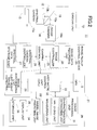
FIG.2 is a schematical block diagram of a camera unit of the image pickup device and an image pickup control device; -
FIG.3 is an explanatory drawing to show a principle of digital photogrammetry for measuring altitude of a flying object and coordinates of a measuring point from the images, which the flying object has taken from two points; -
FIG.4 is an explanatory drawing on relative orientation in the digital photogrammetry in a case where the camera is tilted; -
FIG.5A and FIG.5B each represents an explanatory drawing to show an optical system of a spectral camera having a transmission type interference filter to be used in an embodiment of the present invention.FIG.5A shows a condition where diaphragm orifice concurs with an optical axis, andFIG.5B shows a condition where the diagram orifice is separated from the optical axis; -
FIG.6 is a graph to show a relation between an incident angle and a peak wavelength of a light, which passes through; -
FIG.7 is a graph to show wavelength transmission characteristics to match an incident angle when the light enters an interference filter; -
FIG.8A and FIG.8B each represents an explanatory drawing to show an optical system having a reflection type interference filter in another spectral camera to be used in the embodiment of the present invention.FIG.8A shows a condition where a diaphragm orifice concurs with the optical axis andFIG.8B shows a condition where the diaphragm orifice is separated from the optical axis; -
FIG.9A and FIG.9B each represents an explanatory drawing to show an optical system having a reflection type interference filter in still another spectral camera to be used in the embodiment of the present invention.FIG.9A shows a condition where a diaphragm orifice concurs with the optical axis andFIG.9B shows a condition where the diaphragm orifice is separated from the optical axis; -
FIG.10 is a front view to show the interference filter provided with a plurality of interference membranes with different characteristics; -
FIG.11 is an explanatory drawing to show a condition to acquire a hyper-spectral image in the present embodiment; -
FIG.12A and FIG.12B each represents an explanatory drawing to show conditions between images in a case where a plurality of images are acquired by a helicopter flying in hovering state; -
FIG.13 is a flow chart to show operation in an embodiment of the present invention; -
FIG.14 is a flow chart to show details ofStep 03 andStep 08 inFIG.13 ; and -
FIG.15 is a flow chart to explain operation in a second embodiment of the present invention. - Description will be given below on embodiments of the present invention by referring to the attached drawings.
- An image acquiring device of an embodiment of the present invention is mounted on a small Unmanned Aerial Vehicle (UAV), e.g. a small type helicopter which can be operated by remote control operation or can fly autonomously.
-
FIG.1 shows a small flying object 1 where an image acquiring device according to the present embodiment is mounted. - In
FIG.1 ,reference numeral 2 represents a base station control device to be installed on ground surface. The basestation control device 2 can perform data communication to and from a flying object 1 and the basestation control device 2 controls flight of the flying object 1, sets and changes flight plan, and stores and manages information collected by the flying object 1. - The flying object 1 is a helicopter used as a small type flying object which flies autonomously. This helicopter 1 is operated by remote control from the base
station control device 2. Or, the flight plan is set up on a control device (not shown) of the helicopter 1 from the basestation control device 2, and the control device controls navigation means (to be described later) and autonomous flight is performed according to the flight plan. The control device controls the navigation means and controls the helicopter 1 at a predetermined speed and at a predetermined altitude, and also can control the helicopter 1 in hovering state (stationary flying condition) at a certain predetermined position. - The helicopter 1 has a
helicopter body 3, and as many propellers as required mounted on the helicopter body 3 (e.g. four sets ofpropellers propellers propellers - On the
helicopter body 3, aGPS device 9 for measuring a reference position of the helicopter 1 is mounted. - On the
helicopter body 3 of the helicopter 1, animage pickup device 11 is provided on board. Theimage pickup device 11 has anoptical axis 12, and theoptical axis 12 is designed to be extended in downward direction so that theimage pickup device 11 takes image of positions in downward direction of the helicopter 1. - Next, referring to
FIG.2 , description will be given on approximate arrangement of theimage pickup device 11. - The
image pickup device 11 has acamera unit 13 and an imagepickup control device 21. The imagepickup control device 21 can perform digital photogrammetry of an object to be measured based on image data as acquired by thecamera unit 13 and based on position information from theGPS device 9 and performs processing such as synthesizing of optical spectral data acquired by thecamera unit 13 with the image data or other types of processing. - First, description will be given on the
camera unit 13. - The
camera unit 13 comprises animage camera 14 used as a first camera and aspectral camera 15 used as second camera. Theoptical axis 12 is divided by a half-mirror 16. Theimage camera 14 is provided on oneoptical axis 12a, and thespectral camera 15 is provided on the otheroptical axis 12b. Theimage camera 14 acquires an image as it is (real image) of an object to be measured, and thespectral camera 15 acquires an optical spectral image. - As described above, the
image camera 14 and thespectral camera 15 have theoptical axis 12 in common, and theimage camera 14 and thespectral camera 15 are in a known relation. Or, theimage camera 14 and thespectral camera 15 may be separately provided. Also, the optical axis of theimage camera 14 and the optical axis of thespectral camera 15 are set in parallel to each other. A distance between the optical axes is already known, and theimage camera 14 and thespectral camera 15 are set in a known relation to each other. - The
image camera 14 takes images at the points to be measured and outputs digital image data. Theimage camera 14 may be a camera to take a still image at a predetermined time interval or may be a video camera to continuously take images. - The
image camera 14 has a CCD or CMOS sensor, which is an aggregate of pixels, as animage pickup element 14a, and a relation between theoptical axis 12a and theimage pickup element 14a is set in such a manner that theoptical axis 12a passes perpendicularly the center (i.e. the center of coordinates of a photodetection surface) of theimage pickup element 14a. Therefore, it is so designed that each pixel of theimage pickup element 14a can specify the position on theimage pickup element 14a, and further that a field angle of each pixel (i.e. an angle with respect to the optical axis 12) can be identified. - The
spectral camera 15 has a CCD or CMOS sensor, which is an aggregate of pixels, as animage pickup element 15a, similarly to the case of theimage camera 14, and a relation between theoptical axis 12b and theimage pickup element 15a is set in such a manner that theoptical axis 12b passes perpendicularly the center of theimage pickup element 15a (i.e. the center of coordinates of photodetection surface). Therefore, each pixel of theimage pickup element 15a can identify a position (coordinate) on theimage pickup element 15a and a field angle of each pixel (i.e. an angle with respect to the optical axis 12) can be identified. Further, each pixel of theimage pickup element 15a and each pixel of theimage pickup element 14a match in a one-to-one relation. - Now, description will be given on an image
pickup control device 21. - The image
pickup control device 21 comprises an arithmetic control unit (CPU) 22, an imagedata recording unit 23, animage controller 24, acamera control unit 25, aspectral camera controller 26, a spectraldata storage unit 27, animage synthesizing unit 28, animage processing unit 29, acharacteristics extracting unit 31, amatching unit 32, a measuringunit 33, a modelimage preparing unit 34, adisplay unit 35, and astorage unit 36. - The
camera control unit 25 controls theimage camera 14 and thespectral camera 15 synchronously. Theimage controller 24 drives theimage camera 14 based on an instruction signal from thecamera control unit 25 and takes image data (real image data). The image data thus acquired are associated with image pickup time and are stored in the imagedata recording unit 23. - The
spectral camera controller 26 drives thespectral camera 15 according to an instruction from thecamera control unit 25 and acquires optical spectral image data. The optical spectral image data are associated with time and are stored in the spectraldata storage unit 27. - The
image synthesizing unit 28 synthesizes image data stored in the imagedata recording unit 23 with the optical spectral image data stored in the spectraldata storage unit 27, thereby synthesizing a hyper-spectral image in such a manner that all pixels of one image have optical spectral information. - The
image processing unit 29 has thecharacteristics extracting unit 31 and thematching unit 32, and at least five or more feature points (pass points) can be extracted from image data of one frame. Then, tracking of image or matching of image is performed according to the feature points on the image data different in terms of time or according to the image data acquired from different image pickup points. - For the image tracking and the image matching, SSDA method (sequential similarity detection algorithm), the normalized cross-correlation method, the least square matching method, etc. are used.
- The measuring
unit 33 fulfills the functions to execute digital photogrammetry based on two image data acquired by theimage camera 14 from different image pickup positions. - The model
image preparing unit 34 is used to associate distance data of each pixel measured by the measuringunit 33 with the hyper-spectral image, and to prepare a model image, which has four-dimensional data, i.e. two-dimensional position data (plane coordinates data) + optical spectral data + height data. - In the
storage unit 36, various types of programs are stored. These programs include: a program needed for camera control, a program needed for synthesis of image data and optical spectral image data, a program needed for image processing, a program needed for measurement, a program needed for preparation of model image, a program for controlling thedisplay unit 35, etc. The imagedata recording unit 23 and the spectraldata storage unit 27 may be prepared in a part of thestorage unit 36. - Next, referring to
FIG.3 andFIG.4 , description will be given on distance measurement by digital photogrammetry. - It is supposed here that in
FIG.3 , the helicopter 1 flies from a point O1 to a point O2, and that the images are taken at the point O1 and at the point O2. A distance B from the point O1 to the point O2 is a photographing base length. A numeral 41-1 and a numeral 41-2 each represents animage pickup element 41 of theimage pickup device 11 at the point O1 and the point O2 respectively, and the image pickup element 41-1 and 41-2 are equivalent to the image data.FIG.3 shows a case that theoptical axis 12 of theimage pickup device 11 runs in vertical direction, i.e. a case where the helicopter 1 is in horizontal posture. - A position of a measuring point P on the image as taken at the point O1 (i.e. a position on the image pickup element) will be p1 (x1, y1), and a position of the measuring point P on the image as taken at the point O2 (i.e. a position on the image pickup element) will be p2 (x2, y2). Focal length f of the
image pickup device 11 and a distance Z from the photographing base length B to the point P, (height distance of the helicopter 1), is determined from relation of similarity of a triangle (O1, O2 and P), a triangle (O1, p1) and a triangle (O2, p2) as:
- Here, ground surface coordinates of the point O1 and the point O2 can be measured by the
GPS device 9. The photographing base length B is a distance between two points, i.e. a distance between the point O1 and the point O2, and the photographing base length B can be obtained based on the result of measurement by theGPS device 9. Also, geocentric positions (plane coordinates) of the measuring point P can be determined similarly from p1 (x1, y1) and p2 (x2, y2) and from the geocentric positions of the point O1 and the point O2 as measured by theGPS device 9. - Therefore, from two images sequentially taken in the process of the moving of the helicopter 1, an altitude of the helicopter 1 (i.e. an altitude from the ground surface) can be determined at real time (measurement of an altitude distance).
- In the digital photogrammetry as described above, p1 (x1, y1) and p2 (x2, y2) correspond to a point common to a
left image 42 taken at the point O1 and aright image 43 taken at the point O2, and P1 and P2 are called as pass points. - The point p1 in the
left image 42 can be obtained as a feature point by image processing such as edge processing or other processing on theleft image 42 acquired at the point O1. InFIG.4 , only one point is shown. Actually, however, a multiple of points are extracted as the feature points. - A procedure to specify the point p2, which corresponds to the point p1, in the
right image 43 is performed by a process called video image tracking. The video images are made up by frame images, which are continuous in time series. - In the video image tracking, the video images (frame images) are continuously acquired from the point O1 to the point O2, and a preset range including the point p1 in one frame image is set up in a searching range. In the searching range within the next frame images, which are adjacent to each other in terms of time, a point to correspond to the point p1 is searched, and further, the point is specified. The searching within the preset range with respect to the next frame image and the specifying are repeatedly performed, and the point p2 is finally specified in the
right image 43. - The video image tracking is described in the Japanese Patent Application Publication
JP-A-2006-10376 - The helicopter 1 is controlled at horizontal position by a flight control unit (not shown), but the horizontal posture may be disturbed under the influence of various causes such as wind. For this reason, the posture of the
image pickup device 11 at the point O1 may be different from the posture of theimage pickup device 11 at the point O2.FIG.4 is a schematical drawing to show condition of an image pickup element 41-1 as taken at the point O1 and tilting condition of an image pickup element 41-2 as taken at the point O2. Theleft image 42 obtained by the image pickup element 41-1 and theright image 43 taken by the image pickup element 41-2 are also in similar conditions. - Using a vertical axis (Z-axis) of the
optical axis 12 as reference, the tilting of the image is represented by a rotation angle κ around Z-axis as the center, by a rotation angle ω around a first horizontal axis (X-axis) as the center, and by a rotation angle φ around a second horizontal axis (Y-axis) as the center. By relative orientation on the image taken at the point O1 and an image taken at the point O2 and by using κ, ω, and φ as variables, the condition can be converted to a condition as shown by broken line in the figure (i.e. a condition shown inFIG.3 ). By performing the relative orientation, three-dimensional coordinates of the measuring point P can be calculated. Further, altitudes of the helicopter 1 at the point O1 and at the point O2 can be determined. - Here, rotation angle of each of three axes at the point O1 and the point O2 can be measured by a gyro unit (not shown), and coordinates (x1, y1) of the point p1 in the image at the point O1 and coordinates (x2, y2) of the point p2 in the image at the point O2 can be measured from the positions of pixels of the
image pickup element 41. Accordingly, it is assumed here that the coordinates of p1 in a converted coordinate system (model coordinates) after the relative orientation are (X1, Y1, Z1), and the coordinates of p2 in the converted coordinate system (model coordinates) after the relative orientation are (X2, Y2, Z2), and also, that focal length of theimage pickup device 11 is f. - Then, the coordinates of p1 and p2 in the converted coordinate system (model coordinates) can be represented as given below:


- Therefore, three-dimensional coordinates of the measuring point P can be calculated in the same manner as shown in
FIG.3 based on the coordinates (X1, Y1, Z1) of p1 and on the coordinates of p2 (X2, Y2, Z2) (absolute orientation). - Next, description will be given on an example of the
spectral camera 15 as used in the present embodiment by referring toFIG.5A and FIG.5B . -
FIG.5A and FIG.5B each represents anoptical system 45 of thespectral camera 15. - In each of
FIG.5A and FIG.5B ,reference numeral 46 represents an optical axis of theoptical system 45, and anobjective lens 47, afirst relay lens 48, asecond relay lens 49, athird relay lens 50, animage forming lens 51, and animage pickup element 52 are arranged along theoptical axis 46. Also, inFIG.5A and inFIG.5B ,reference numeral 53 represents an image formed by theobject lens 47 and a reference symbol f represents a focal length of thesecond relay lens 49. Theobjective lens 47 and thefirst relay lens 48 schematically show a first optical system, and thesecond relay lens 49 schematically shows a second optical system. - A
diaphragm 55, acting as a luminous flux selecting member, is disposed on the side (closer to the second relay lens 49) of thefirst relay lens 48. Thediaphragm 55 has a slit-like diaphragm orifice 55a, which is extended in a direction perpendicular to paper surface in the figure. Thediaphragm 55 is disposed at a focal position of thesecond relay lens 49 closer to object side or nearly at its focal position, and thediaphragm 55 is supported in such a manner that thediaphragm 55 is movable along a direction perpendicular to the optical axis 46 (i.e. a direction perpendicularly crossing thediaphragm orifice 55a) and that the position of thediaphragm 55 can be changed by an adequate position displacing means such as a linear motor or the like. - Here, the
diaphragm 55 and thesecond relay lens 49 make up together a tele-centricoptical system 56. After passing through thefirst relay lens 48, luminous fluxes are split by the tele-centricoptical system 56 to a multiple of luminous fluxes (a principal ray 57) running in parallel to each other. - An
interference filter 58 with a transmission type interference film is provided on a converging position of the principal ray 57 (at an image-forming position or at an approximately image-forming position by the second relay lens 49). Theinterference filter 58 fulfills the function as a wavelength selecting filter. From light beams with specific wavelength after passing through theinterference filter 58, an image is formed on theimage pickup element 52 by thethird relay lens 50 and the image-forminglens 51. The image thus formed will be a two-dimensional image formed with the specific wavelength. - The
interference filter 58 has such property that wavelength selecting characteristics are changed according to incident angle of the light beam entering theinterference filter 58.FIG.6 shows a relation between an incident angle and the peak wavelength of the light, which passes through (i.e. incident angle dependency of the peak wavelength), and by changing the incident angle, it can be known that the peak wavelength is changing. - As shown in
FIG.5A , thediaphragm orifice 55a of thediaphragm 55 is positioned on theoptical axis 46. In this case, theprincipal ray 57 runs in parallel to theoptical axis 46. Next, in a case where the diagram 55 is moved as shown inFIG.5B - for instance, in a case where the diagram 55 is moved in upward direction as shown in the figure, theprincipal ray 57 is tilted with respect to theoptical axis 46. That is, incident angle with respect to theinterference filter 58 is changed. Therefore, by moving thediaphragm 55, the wavelength of the light passing through theinterference filter 58 can be changed. - For instance, referring to
FIG.6 , when the incident angle with respect to theinterference filter 58 is changed, peak of the wavelength of the light passing is changed in the range of 600 nm to 520 nm. This means that theinterference filter 58 has wavelength selection range W of 600 nm to 520 nm.FIG.7 shows wavelength transmission characteristics to match the incident angle to theinterference filter 58. - Next, in
FIG.5A and FIG.5B , theinterference filter 58 is tilted with respect to theoptical axis 46. As shown inFIG.6 , incident angle dependency will be linear from a point where the incident angle exceeds 10°. Accordingly, by tilting theinterference filter 58 in advance, the change of the selected wavelength with respect to the displacement of thediaphragm 55 can be effectively obtained. - Therefore, by acquiring the image by the
image pickup element 52 each time thediaphragm 55 is displaced and by using theinterference filter 58 with the wavelength transmission characteristics shown inFIG.6 , light spectrum in the wavelength range of 600 nm to 520 nm can be acquired. When the light spectrum is acquired in the wavelength range exceeding the range of 600 nm to 520 nm, theinterference filter 58 can be replaced with an interference filter having a different wavelength selection range W'. -
FIG.7 shows an example of optical spectrum, which is obtained when angle of theinterference filter 58 is changed to 0°, 10°, 20°, 30° and 40° respectively. -
FIG.8A and FIG.8B each represents a variation example of anoptical system 45 as shown inFIG.5A and FIG.5B respectively. - In the
optical system 45 shown inFIG.5A and FIG.5B , a transmissiontype interference filter 58 is used. As shown inFIG.8A and FIG.8B , an optical system 45' may be arranged by using a reflection type interference filter 58'. The interference filter 58' has a reflection type interference film formed on a reflection mirror. In the optical system 45', wavelength is selected when the light is reflected by the interference filter 58'. - In
FIG.8A and FIG.8B , the same component as shown inFIG.5A and FIG.5B respectively is referred by the same symbol, and detailed description is not given here. - In the variation example as described above, when a
diaphragm 55 is moved as shown inFIG.8B , incident angle of aprincipal ray 57 to the interference filter 58' is changed, and a light with a specific wavelength in a predetermined wavelength selection range W is selectively reflected. - When a reflection type filter 58' is used as the interference filter, the optical system 45' can be set in a compact arrangement.
-
FIG.9A, FIG.9B andFIG.10 each represents another variation example. - The variation example shown in each of
FIG.9A, FIG.9B andFIG.10 has the same arrangement as the optical system 45' shown in the variation example ofFIG.8A and FIG.8B , and a reflectiontype interference filter 62 is used. - The
interference filter 62 is in shape of a circular disk as shown inFIG.10 , and is rotatably supported via arotation axis 59. In theinterference filter 62, reflection surface is equally divided (divided in 6 equal parts in the figure) in circumferential direction. Because the reflection surface is divided, divided reflection surfaces 63a to 63f can be formed as many as required (divided to 6 parts in the figure), and a different reflection interference filter with different wavelength selection characteristics is formed for each of the divided reflection surfaces 63a to 63f. - For instance, a reflection interference film having selection wavelength λ1 400 nm - 450 nm is formed on the divided
reflection surface 63a. Similarly, a reflection interference film having selection wavelength λ2 of 450 nm to 525 nm is formed on the dividedreflection surface 63b, a reflection interference film having selection wavelength λ3 of 525 nm - 650 nm is formed on the dividedreflection surface 63c, a reflection interference film having selection wavelength λ4 of 650 nm - 750 nm is formed on the dividedreflection surface 63d, a reflection interference film having selection wavelength λ5 of 750 nm - 870 nm is formed on the dividedreflection surface 63e, and a reflection interference film having selection wavelength λ6 of 870 nm - 950 nm is formed on the dividedreflection surface 63f. - An
objective lens 47, afirst relay lens 48, and adiaphragm 55 are arranged along anoptical axis 46. Asecond relay lens 49 is arranged along an optical axis, which runs in parallel to theoptical axis 46 and is separated from theoptical axis 46 at a predetermined distance, and theinterference filter 62 is arranged at a position opposite to thesecond relay lens 49. Luminous fluxes reflected by theinterference filter 62 are deflected by areflection mirror 64, and the luminous fluxes thus deflected pass through animage forming lens 51, and an image is formed on animage pickup element 52. InFIG.10 ,reference numeral 57a represents an image formed by aprincipal ray 57. - In this another example, the
first relay lens 48 and thediaphragm 55 are at positions deviated from theoptical axis 46 of thesecond relay lens 49, therefore theprincipal ray 57, which is divided by the tele-centricoptical system 56, enters theinterference filter 62 in tilted condition. Further, as shown inFIG.9B , when thediaphragm 55 is moved so that thediaphragm 55 is separated from theoptical axis 46, the incident angle of theprincipal ray 57 will be still larger. Therefore, by moving thediaphragm 55, it is possible to change the selected wavelength. - Further, when the optical spectrum to be obtained is in the range of 400 nm to 950 nm, the divided reflection surface is sequentially changed over from the divided
reflection surface 63a to the dividedreflection surface 63f. Thediaphragm 55 is moved for each of the divided reflection surface 63 thus changed over, and an image is acquired with wavelength for each of the position, to which thediaphragm 55 is moved. The changeover of the divided reflection surfaces 63a to 63f is performed synchronously with the moving of thediaphragm 55. Each time the divided reflection surfaces 63 are changed over, the slit hole returns to a position separated at the most from the position of the optical axis 46 (i.e. reference position), and then thediaphragm 55 is moved for each predetermined amount. - By associated operation of the rotation of the
interference filter 62 with the moving of thediaphragm 55, the wavelength is selected in the range of 400 nm to 950 nm. An image is acquired by theimage pickup element 52 for each of the selected wavelength, and an optical spectrum can be obtained for total range of 400 nm to 950 nm. - In a case where the wavelength range of the optical spectrum to be obtained is limited, a divided reflection surface having the corresponding wavelength selection characteristics may be selected and the optical spectrum is obtained.
- In the above, it is described that the
interference filter 62 is designed in form of a circular disk and theinterference filter 62 can be rotated, while it may be so arranged that theinterference filter 62 is designed in form of a long rectangle, and that theinterference filter 62 is divided in longitudinal direction to form the divided reflection surfaces. Then, theinterference filter 62 is slid in longitudinal detection and the divided reflection surface may be changed over. - In the embodiment as shown in each of
FIG.5A and FIG.5B , it may be so arranged that the disk of a transmissiontype interference filter 58 is equally divided to a predetermined number of disks, and an interference film having different wavelength characteristics for each divided part is formed. Then, similarly to the variation examples shown in each ofFIG.9A, FIG.9B andFIG.10 , theinterference filter 58 is rotated and the optical spectral image for each of the divided parts may be acquired. - Now, referring to
FIG.11 , description will be given below on operation in the present embodiment. The following description describes a case where the interference filter is divided, and the site thus divided has different transmission characteristics in anoptical system 45 as shown inFIG.5A and FIG.5B or in an optical system 45' shown inFIG.8A, FIG.8B and inFIG.9A and FIG.9B as aspectral camera 15. - As described above, in the present embodiment, a real image and an optical spectral image are acquired.
- A still image (an left image 42) is acquired at a point O1 by the
image camera 14, and the position of point O1 is measured by theGPS device 9. The still image acquired is stored in the imagedata recording unit 23. Further, from the still image at the point O1, at least five feature points (preferably, a multiple number of the feature points) are extracted by theimage processing unit 29. When the helicopter 1 is moved from the point O1 to the point O2, tracking by video image is performed on the feature points. Then, a still image (a right image 43) is acquired at the point O2 by theimage camera 14. By theGPS device 9, the position of the point O2 is measured. By theimage processing unit 29, at least five of the feature points are specified in the still image at the point O2, and matching is performed on the still image at the point O1 and on the still image at the point O2 according to the feature points. Further, by the measuringunit 33, digital photogrammetry is performed based on the still image acquired at the point O1 and the still image acquired at the point O2. - At the same time as the acquisition of the still images at the point O1 and at the point O2, an optical spectral image is acquired by the
spectral camera 15. - To acquire the optical spectral image, the helicopter 1 is set in stationary state (in hovering state), and the position of the
diaphragm 55 is sequentially changed. The wavelength to be selected by theinterference filter 58 is changed, and an image is acquired for each of the wavelength thus selected. The optical spectral image is acquired with a range of wavelength set up in advance. - In a case where the range of the wavelength thus set up (i.e. λ1 to λn) exceeds the range of the wavelength, which is obtained by changing the incident angle of the
principal ray 57 on one interference film, theinterference filter 58 is rotated, and wavelength characteristics of the site where theprincipal ray 57 enters are changed. Further, optical spectrum in the wavelength range obtained by the moving of thediaphragm 55 is acquired. - The optical spectral images acquired as described above are stored in the spectral
data storage unit 27. - By synthesizing the optical spectral images stored at the point O1 and at the point O2 respectively, an optical spectrum synthesized image including the optical spectral images acquired at the point O1 and at the point O2 in the preset wavelength range (λ1 to λn) can be synthesized. Further, by synthesizing the optical spectral synthesized image at the point O1 and the still image at the point O1, a hyper-spectral images acquired at the point O1 is synthesized. Then, by synthesizing the optical spectrum synthesized image at the point O2 and the still image at the point O2, a hyper-spectral image acquired at the point O2 is synthesized.
- Further, image matching (stereo-matching) is performed on the still image at the point O1 and on the still image at the point O2 based on the feature points. Then, by associating the results of the digital photogrammetry with the still images, an image having three-dimensional positional data (3D model image) can be prepared. Further, at least one of the optical spectral synthetic image at the point O1 and the optical spectral synthetic image at the point O2 is associated with the 3D model image.
- As described above, the still image and the optical spectral image correspond to each other in a one-to-one relation, and when one point in the still image is specified, an optical spectrum at the specified point can be immediately acquired from the spectral synthetic image, and three-dimensional positional data can be obtained from the 3D model image.
- Thus, the hyper-spectral images can be acquired at the point O1 and at the point O2, and a 3D model image having the optical spectral information, i.e. a 4D model image, can be acquired.
- Therefore, it is possible to recognize a growing condition of agricultural products from the optical spectrum, and to identify the size of the agricultural product from three-dimensional data of the agricultural product. Or, it is possible to acquire information of the ground surface which includes information of the type of substance exposed at the same time.
- Next, when the helicopter 1 is set in hovering state and the optical spectral image is acquired, the posture is constantly changing, and this condition cannot be defined as a complete standstill. Therefore, there are some differences in the images, which are acquired for each of the wavelengths. For this reason, if the optical spectral images stored in the spectral
data storage unit 27 are synthesized as they actually are, a problem may arise such that error occurs, or the images are blurred (grow dim) or other problems. -
FIG.12A and FIG.12B each represents a condition where optical spectral images, each having selected wavelength of λ1, λ2, λ3 and λ4 respectively, are acquired in hovering state. Reference symbol S1 inFIG.12A represents a condition where animage pickup device 11 is in completely standstill condition in hovering state, and reference symbol S2 represents a condition where theimage pickup device 11 is moving.FIG.12B is a drawing where optical spectral images of λ1, λ2, λ3 and λ4 acquired when theimage pickup device 11 are moving are developed according to the course of time. In the figure, black circle represents a feature point extracted. As it is seen inFIG.12A and FIG.12B , when the images are synthesized as they actually are, the feature points do not concur with each other between the images, and it is seen that error has occurred or the images are blurred. - Accordingly, it is necessary that the matching (relative positioning) is performed so as to be able to synthesize optical spectral images which are acquired for each of the wavelengths in the hovering state.
- By the
spectral camera 15, even in the operation to take images of the optical spectral images, real images can be acquired at predetermined time interval as set in advance (or in continuous images) by theimage camera 14 in synchronization with thespectral camera 15, and the image tracking is carried out. - Feature points are extracted for each of the frame images, and image tracking is sequentially performed on the feature points for the frame images, which are adjacent to each other in terms of time, and the feature points obtained in a frame image preceding in term of time (hereinafter, referred as "the first frame image") are specified in a subsequent frame image (hereinafter, referred as "the second frame image").
- Based on the feature points, positioning is performed between the preceding frame image and the subsequent frame image. Based on the condition obtained by this positioning, positioning (matching) can be performed for the optical spectral image corresponding to the preceding frame image and a subsequent optical spectral image corresponding to the subsequent frame image.
- In a case where the optical spectral image is acquired for each of the frame images, the image tracking is carried out continuously for the frame image.
- By the image tracking, the feature points are specified to the first frame image, which corresponds to an optical spectral image preceding in terms of time (hereinafter, referred as "the first optical spectral image"). Further, the feature points are specified for the second frame image, which corresponds to the optical spectral image adjacent in terms of time (the second optical spectral image).
- In a case where the time elapses between the first frame image and the second frame image, and tilting of the optical axis or the like occurs between these two images, coordinates conversion is carried out according to the feature points between the two frame images, and the image matching is performed.
- As described above, the real image acquired by the
image camera 14 and the optical spectral image acquired in synchronization with the real image correspond to each other in a one-to-one relation. Thus, the condition obtained by the coordinates conversion between the first frame image and the second frame image can be directly applied to the matching of the first optical spectral image and the second optical spectral image. - Further, by carrying out the matching (synthesizing) of the optical spectral imaged in parallel to the matching of the real images, synthesis of the optical spectral images without error can be carried out.
- When the synthesis of the optical spectral images as described above is sequentially performed on all of the optical spectral images as acquired in the hovering state, it is possible to acquire the optical spectral synthesized image similar to the optical spectral images as acquired in the standstill state.
- By referring to
FIG.13 andFIG.14 , description will be given below on the digital photogrammetry and on acquisition and synthesis of the optical spectral image and the hyper-spectral image or the like. - (Step 01) The hovering of the helicopter 1 is started at the point O1, and the
left image 42 is acquired by theimage camera 14 at the point O1. Also, the measurement of the position of the helicopter 1 (i.e. the position O1) by theGPS device 9 is carried out. - (Step O2) The feature points are extracted by the procedure such as edge processing on the
left image 42 acquired. - (Step 03) The video images are acquired by the
image camera 14, and the optical spectral images are acquired by thespectral camera 15 in synchronization with the operation of theimage camera 14. Image tracking at the same position (hereinafter, referred as "the same position tracking") is carried out at the same position by the video images in parallel to the acquisition of the optical spectral images. Based on the result of the video image tracking, image position correcting is performed between each of the optical spectral images. - Now, description will be given on the acquisition of optical spectral images at the point O1 and on the image position correcting in
Step 21 to Step 25. - (
Step 21 and Step 221) The optical spectral images in the predetermined wavelength range (λ1 to λn) are acquired for each wavelength in a predetermined time interval. The optical spectral images thus acquired are stored in the spectraldata storage unit 27 in time series. At the same time as the acquisition of the optical spectral images, video images (the real images acquired by the image camera 14) are acquired (Step 222). During the time interval when the optical spectral images are acquired, the video images are continuously acquired, and the image tracking is carried out between the frame images which constitute the video images. - (
Step 223 and Step 224) In the image tracking (the same position tracking), the feature points are extracted from the frame image (the first frame image), which is synchronized in terms of time with the acquisition of the optical spectral image (λ1), and the feature points are specified by the image tracking to the subsequent frame image adjacent in terms of time. The image tracking is carried out continuously, and the feature points are specified on the frame image (the second frame image) synchronized with the subsequent optical spectral image (λ2), which are adjacent in terms of time. - (Step 23) Based on the feature points of the first frame image thus acquired and on the feature points of the second frame image, the matching is performed between the first frame image and the second frame image, and the coordinates conversion is performed between the first frame image and the second frame image is carried out.
- The
image camera 14 and thespectral camera 15 acquire the images on the same axis. Each pixel of the frame image and each pixel of the optical spectral images correspond to each other in a one-to-one relation, and the condition of the matching of the frame images and the conditions of coordinates conversion can also be applied to the optical spectral images, which are adjacent to each other in terms of time. - (Step 24) It is judged whether all spectral images with all wavelengths are acquired or not. If all spectral images are not acquired, it is returned to
Step 221 andStep 222, and the acquisition of the optical spectral image and the same position tracking are carried out continuously. - (Step 25) When the optical spectral images for all wavelengths of a predetermined wavelength range (λ1 to λn) have been acquired, all optical spectral images are synthesized under the condition obtained by the video image tracking and the optical spectral synthesized images having optical spectra in the predetermined wavelength range (λ1 to λn) at the point O1 can be acquired. Further, by synthesizing the optical spectral synthesized image with the still images, the hyper-spectral image can be acquired.
- (
Step 04 to Step 06) When the still image and the hyper-spectral image at the point O1 have been acquired, the helicopter 1 is moved to the point O2. During the moving, the video image is acquired by theimage camera 14, and the image tracking (moving tracking) is performed. The moving tracking may be carried out based on the feature points extracted at theleft image 42 or the moving tracking may be carried out by using the feature points finally obtained by the same position tracking in hovering state. - (Step 07) When the helicopter 1 reaches the point O2, the moving tracking is completed. The hovering is started, and the
right image 43 is acquired. - (Step 08) In the hovering state, while acquiring the video images by the
image camera 14, the optical spectral image is acquired by thespectral camera 15 in synchronization with theimage camera 14. The image tracking at the same position (the same position tracking) by the video image is executed at the same time as acquiring of the optical spectral image, and correction of the image position between the optical spectral images is carried out based on the result of the same position tracking. - The procedures of
Step 21 to Step 25 are carried out, and optical spectral images for all wavelengths of the predetermined wavelength range (λ1 to λn) at the point O2 are acquired and the optical spectral synthesized images having optical spectra in the predetermined wavelength range (λ1 to λn) at the point O2 are acquired by synthesizing all optical spectral image thus obtained. Further, by synthesizing the optical spectral synthesized images with theright image 43, the hyper-spectral image is acquired. - (
Step 09,Step 10 and Step 11) Based on the feature points specified in theright image 43 and on the feature points specified in theleft image 42, matching is performed. Also, coordinates conversion (relative orientation) with one of theleft image 42 or theright image 43 as reference is conducted. Further, the coordinates conversion (absolute orientation) to the geocentric coordinates is carried out based on a result of measurement at the point O1 and O2 by theGPS device 9. - (
Step 12 and Step 13) Based on the result of the absolute orientation, stereo-matching of theleft image 42 and theright image 43 is conducted, and a topographical 3D model having three-dimensional positional data is obtained. - (Step 14) As described above, since the optical spectral image and the still image correspond to each other in a one-to-one relation, the three-dimensional positional data are acquired at a position where the optical spectra are obtained. By synthesizing the optical spectral image with the 3D model, a four-dimensional model having the topographical three-dimensional positional data and the optical spectral information can be prepared.
- Next, referring to
FIG.15 , description will be given on a second embodiment. - In the second embodiment, the arrangement that an
image pickup device 11 shown inFIG.2 is mounted on a helicopter 1 as shown inFig. 1 is the same as in the case of the first embodiment, and detailed description is not given here. - In the second embodiment, without the hovering of the helicopter 1 at the point O1 and at the point O2, still images of a
left image 42 and aright image 43 are acquired at the point O1 and at the point O2 by theimage camera 14. Further, in a process where the helicopter is moved continuously from the point O1 to the point O2, the optical spectral image is acquired by aspectral camera 15. The flying speed of the helicopter 1 is such that there is no substantial deviation between the optical spectral images, which occur as reversed in terms of time. - (
Step 31 to Step 38) Theleft image 42 is acquired at the point O1. At least five of the feature points are extracted by the procedure such as edge processing of theleft image 42 or other processing. Further, the video images are continuously acquired by theimage camera 14, and the feature points are specified in the frame images, which constitute the video images. Then, in synchronization with the acquisition of the video images, in synchronization with each frame image, or in synchronization with the frame images acquired at two or more time intervals, optical spectral images can be acquired by thespectral camera 15. - Between the frame images which are adjacent to each other in terms of time, the image matching is carried out based on the feature points. Based on the result of the image matching, matching of the optical spectral images corresponding to the frame images is conducted.
- Regarding the optical spectral images sequentially acquired, the sequential matching is performed based on the result of the matching of the video images which are acquired at the same time as the optical spectral images. The optical spectral images are acquired in the intended wavelength range up to the wavelengths (λ1 to λn) until the helicopter reaches the point O2 from the point O1. The synthesis of the optical spectral images is carried out in a manner similar to the procedures in
Step 21 to Step 25 in the first embodiment. - When the helicopter 1 reaches the point O2, the
right image 43 is acquired by theimage camera 14, and the feature points extracted in theleft image 42 are specified in theright image 43. To specify the feature points in theright image 43, the results of the image tracking sequentially between the frame images during the moving should be reflected. - (
Step 39,Step 40 and Step 41) Based on the feature points specified in theright image 43 and also on the feature points specified in theleft image 42, the matching is performed. Relative orientation is carried out either theleft image 42 or theright image 43 as reference. Further, absolute orientation is conducted to the geocentric coordinates system based on the result of measurement of theGPS device 9. - (
Step 42 and Step 43) Based on the result of the absolute orientation, stereo-matching is performed between theleft image 42 and theright image 43, and a topographical 3D model having the three-dimensional positional data is obtained. - (Step 44) Further, by synthesizing the optical spectral image with the 3D model, a four-dimensional model having topographical three-dimensional positional data and the optical spectral information can be prepared.
- As described above, in the second embodiment, it is arranged that the hovering process is omitted and that the optical spectral images in the hovering process are acquired during the moving of the helicopter 1.
- In the embodiment as described above, it is so arranged that two-dimensional images are acquired for each of the specific wavelength as selected by the interference filter as the
spectral camera 15 and by regarding the selection range of the wavelength as the desired wavelength range, the optical spectral images are acquired in the desired wavelength, while the other spectral camera can be adopted for the purpose. By using the other spectral camera, images may be acquired along a line, which goes across a field of view of the camera, and the optical spectral image may be acquired in such a manner that images may be acquired by resolving the images along the line thus obtained to the optical spectra by using diffraction grating and by scanning the line over the total field of view of the camera.
Claims (10)
- An image acquiring device, comprising a first camera (14) for acquiring video images, consisting of frame images acquired at predetermined time intervals, a second camera (15) being in a known relation with said first camera and used for acquiring two or more optical spectral images of an object to be measured, and an image pickup control device (21), wherein said image pickup control device is configured to extract two or more feature points from one of said frame images, to sequentially specify said feature points in the frame images continuous in time series, to perform image matching between the frame images regarding the frame images corresponding to said two or more optical spectral images based on said feature points, and to synthesize said two or more optical spectral images according to the condition obtained by said image matching.
- An image acquiring device according to claim 1, wherein said image pickup control device (21) acquires said frame images and said optical spectral images synchronously, and performs relative positioning of each of the optical spectral images based on a position of said feature point on each frame image.
- An image acquiring device according to claim 1, wherein said image pickup control device (21) extracts at least five feature points from a first frame images of the video images taken by said first camera (14), specifies said at least five feature points in n-th frame image by image tracking, performs stereo-matching based on said feature points of both images, and prepares a three-dimensional model of said object to be measured.
- An image acquiring device according to claim 3, wherein said image pickup control device (21) combines information of wavelength components of said synthesized optical spectral images to said three-dimensional model.
- An image acquiring device according to claim 1, wherein the optical spectral images acquired by said second camera (15) are acquired as two-dimensional images relating to a predetermined wavelength range.
- An image acquiring system, comprising a flying object (1), a GPS device (9) mounted on said flying object, a control device (2) for controlling flight of said flying object, a first camera (14) mounted on said flying object and for acquiring video images made up by frame images acquired at predetermined time intervals, a second camera (15) provided in a known relation with said first camera and for acquiring two or more optical spectral images of an object to be measured, and an image pickup control device (21), wherein said flying object moves from a first point to a second point, said GPS device measures a position of the first point and a position of the second point in geocentric coordinate system, said first camera acquires a still image of the first point, acquires video images during the moving from the first point to the second point, and further, acquires still images at the second point, said second camera acquires two or more optical spectral image in a predetermined wavelength range, said image pickup control device extracts two or more feature points from the still image at the first point, performs video image tracking from the video image during the moving from the first point to the second point, specifies said feature points in the still image at the second point, performs stereo-matching of the still image at the first point with the still image at the second point based on said feature points, prepares a three-dimensional model based on positions of said first point and said second point in the geocentric coordinate system, and said image pickup control device synthesizes two or more optical spectral images, prepares an optical spectral synthetic image, synthesizes said three-dimensional model with said optical spectral synthetic image, and prepares a four-dimensional model having three-dimensional position data and optical spectral information of said object to be measured.
- An image acquiring system according to claim 6, wherein said second camera acquires two or more optical spectral images in a predetermined wavelength range during the hovering flight at the first point and acquires two or more optical spectral images in the predetermined wavelength range during the hovering flight at the second point, said image pickup control device synthesizes two or more optical spectral images of the first point, prepares a first optical spectral synthetic image, synthesizes two or more optical spectral images of the second point, prepares a second optical spectral synthetic image, synthesizes said three-dimensional model with at least one of said first optical spectral synthetic image and said second optical spectral synthetic image, and prepares a four-dimensional model having three-dimensional positional data and optical spectral information of said object to be measured.
- An image acquiring system according to claim 6 or claim 7, wherein said first camera (14) acquires a same position video image in said hovering flight, said image pickup control device (21) performs synchronization on frame image of said same position video image, acquires an optical spectral image by said second camera (15), performs image tracking between frame images, performs image matching of two frame images corresponding to two optical spectral images continuous in terms of time, synthesizes said two optical spectral images under the condition obtained by said image matching, sequentially repeats said image matching of said frame images and synthesizing of the optical spectral images, and synthesizes all optical spectral images acquired during said hovering flight.
- An image acquiring system according to claim 6, wherein said second camera acquires two or more optical spectral images in a predetermined wavelength range during the moving from the first point to the second point.
- An image acquiring system according to claim 9, wherein said image pickup control device (21) performs synchronization of the video image with the frame image, acquires an optical spectral image by said second camera (15), performs image tracking between the frame images, performs image matching of two frame images corresponding to two optical spectral images continuous in terms of time, synthesizes said two optical images under the condition as obtained in said image matching, sequentially repeats said image matching of said frame image and synthesizing of the optical spectral image, and synthesizes all optical spectral images acquired during the course of said moving.
Applications Claiming Priority (1)
| Application Number | Priority Date | Filing Date | Title |
|---|---|---|---|
| JP2011212479A JP5787695B2 (en) | 2011-09-28 | 2011-09-28 | Image acquisition device |
Publications (1)
| Publication Number | Publication Date |
|---|---|
| EP2575367A2 true EP2575367A2 (en) | 2013-04-03 |
Family
ID=47357874
Family Applications (1)
| Application Number | Title | Priority Date | Filing Date |
|---|---|---|---|
| EP12185846A Withdrawn EP2575367A2 (en) | 2011-09-28 | 2012-09-25 | Image acquiring device and image acquiring system |
Country Status (4)
| Country | Link |
|---|---|
| US (2) | US9544575B2 (en) |
| EP (1) | EP2575367A2 (en) |
| JP (1) | JP5787695B2 (en) |
| CN (1) | CN103033169B (en) |
Cited By (5)
| Publication number | Priority date | Publication date | Assignee | Title |
|---|---|---|---|---|
| CN104318583A (en) * | 2014-11-14 | 2015-01-28 | 武汉大学 | Visible light broadband spectrum image registration method |
| US20150145954A1 (en) * | 2013-11-27 | 2015-05-28 | Honeywell International Inc. | Generating a three-dimensional model of an industrial plant using an unmanned aerial vehicle |
| WO2016022188A3 (en) * | 2014-07-31 | 2016-03-31 | Raytheon Company | Video-assisted landing guidance system and method |
| US10054438B2 (en) | 2014-07-07 | 2018-08-21 | Vito Nv | Method and system for geometric referencing of multi-spectral data |
| ES2749734A1 (en) * | 2018-09-21 | 2020-03-23 | Univ Madrid Carlos Iii | Mobile 3D imaging device using a flat laser beam |
Families Citing this family (38)
| Publication number | Priority date | Publication date | Assignee | Title |
|---|---|---|---|---|
| JP5787695B2 (en) | 2011-09-28 | 2015-09-30 | 株式会社トプコン | Image acquisition device |
| US20150254861A1 (en) * | 2012-10-18 | 2015-09-10 | T. Eric Chornenky | Apparatus and method for determining spatial information about environment |
| EP2787319A1 (en) | 2013-04-05 | 2014-10-08 | Leica Geosystems AG | Control of an image triggering system for taking aerial photographs in nadir alignment for an unmanned aircraft |
| JP6224354B2 (en) * | 2013-05-31 | 2017-11-01 | 株式会社トプコン | Spectral image acquisition device and spectral image acquisition method |
| US9562771B2 (en) * | 2013-12-18 | 2017-02-07 | Sharper Shape Ltd | Analysis of sensor data |
| CN104777847A (en) * | 2014-01-13 | 2015-07-15 | 中南大学 | Unmanned aerial vehicle target tracking system based on machine vision and ultra-wideband positioning technology |
| KR102224716B1 (en) * | 2014-05-13 | 2021-03-08 | 삼성전자주식회사 | Method and apparatus for calibrating stereo source images |
| JP6460700B2 (en) * | 2014-09-26 | 2019-01-30 | 株式会社トプコン | Method for diagnosing whether there is a defect on the inner wall of the tunnel and a program for diagnosing the presence of a defect on the inner wall of the tunnel |
| KR102281184B1 (en) * | 2014-11-20 | 2021-07-23 | 삼성전자주식회사 | Method and apparatus for calibrating image |
| EP3889728A3 (en) | 2014-12-31 | 2021-12-01 | SZ DJI Technology Co., Ltd. | Selective processing of sensor data |
| CN105043544B (en) * | 2015-05-05 | 2017-06-20 | 中山大学 | A kind of image spectrum tracking and system |
| US11140326B2 (en) | 2015-05-22 | 2021-10-05 | The United States Of America, As Represented By The Secretary Of The Navy | Aerial video based point, distance, and velocity real-time measurement system |
| CN104932523A (en) * | 2015-05-27 | 2015-09-23 | 深圳市高巨创新科技开发有限公司 | Positioning method and apparatus for unmanned aerial vehicle |
| US20160371544A1 (en) * | 2015-06-22 | 2016-12-22 | Vivint Solar, Inc. | Photovoltaic measurement system |
| JP2017015527A (en) * | 2015-06-30 | 2017-01-19 | 株式会社トプコン | Wide area sensor system, flight detection method and program |
| US20180222581A1 (en) * | 2015-08-04 | 2018-08-09 | Konica Minolta, Inc. | Gas Detection Device and Gas Detection Method |
| DE102015013104A1 (en) * | 2015-08-22 | 2017-02-23 | Dania Lieselotte Reuter | Method for target approach control of unmanned aerial vehicles, in particular delivery docks |
| US10933997B2 (en) * | 2015-10-02 | 2021-03-02 | Insitu, Inc. | Aerial launch and/or recovery for unmanned aircraft, and associated systems and methods |
| US10218893B2 (en) | 2015-10-27 | 2019-02-26 | Mitsubishi Electric Corporation | Image capturing system for shape measurement of structure, method of capturing image of structure for shape measurement of structure, on-board control device, remote control device, program, and storage medium |
| JP6390054B2 (en) * | 2015-11-05 | 2018-09-19 | 株式会社Zmp | Monitoring system |
| US10254136B1 (en) * | 2016-04-18 | 2019-04-09 | Rockwell Collins, Inc. | Prismatic relative positioning system |
| US11299270B2 (en) | 2016-06-24 | 2022-04-12 | Matthew CULVER | Systems and methods for unmanned aerial vehicles |
| CN106452658B (en) * | 2016-10-25 | 2019-06-07 | 成都紫瑞青云航空宇航技术有限公司 | A kind of low-level defence equipment |
| DE102016224886B3 (en) | 2016-12-13 | 2018-05-30 | Deutsches Zentrum für Luft- und Raumfahrt e.V. | Method and device for determining the cut edges of two overlapping image recordings of a surface |
| CN107063189A (en) * | 2017-01-19 | 2017-08-18 | 上海勤融信息科技有限公司 | The alignment system and method for view-based access control model |
| JPWO2018155159A1 (en) * | 2017-02-24 | 2019-12-19 | パナソニックIpマネジメント株式会社 | Remote video output system and remote video output device |
| US10477180B1 (en) * | 2018-05-22 | 2019-11-12 | Faro Technologies, Inc. | Photogrammetry system and method of operation |
| WO2020006709A1 (en) * | 2018-07-04 | 2020-01-09 | 上海峰飞航空科技有限公司 | Visual positioning system, unmanned aerial vehicle and method for self-detecting position of unmanned aerial vehicle |
| JP2019039913A (en) * | 2018-08-02 | 2019-03-14 | 株式会社Zmp | Monitoring system |
| US11417090B2 (en) * | 2019-02-18 | 2022-08-16 | Nec Corporation | Background suppression for anomaly detection |
| JP7427370B2 (en) | 2019-05-17 | 2024-02-05 | キヤノン株式会社 | Imaging device, image processing device, image processing method, calibration method for imaging device, robot device, method for manufacturing articles using robot device, control program, and recording medium |
| KR102813372B1 (en) * | 2019-12-05 | 2025-05-27 | 삼성전자주식회사 | Dual camera module including hyperspectral camera module, apparatuses including dual camera module and method of operating the same |
| US12301961B2 (en) | 2019-12-05 | 2025-05-13 | Samsung Electronics Co., Ltd. | Dual camera module including hyperspectral camera module, apparatuses including dual camera module, and method of operating the same |
| CN112066950B (en) * | 2020-07-24 | 2022-10-14 | 北京空间机电研究所 | Multi-optical-axis parallel mapping camera single-center projection conversion method |
| US12452503B2 (en) * | 2020-11-10 | 2025-10-21 | Sony Group Corporation | Imaging device |
| CN113487516B (en) * | 2021-07-26 | 2022-09-06 | 河南师范大学 | A dehazing method for image data |
| CN113701883B (en) * | 2021-09-02 | 2023-09-22 | 北京环境特性研究所 | System and method for simulating and measuring spectral characteristics of variable-distance space target |
| KR102815820B1 (en) * | 2023-11-29 | 2025-06-02 | 한국전자기술연구원 | Multi-view hyperspectral image matching method and system |
Citations (1)
| Publication number | Priority date | Publication date | Assignee | Title |
|---|---|---|---|---|
| JP2006010376A (en) | 2004-06-23 | 2006-01-12 | Topcon Corp | Stereo image association method and three-dimensional data creation apparatus |
Family Cites Families (56)
| Publication number | Priority date | Publication date | Assignee | Title |
|---|---|---|---|---|
| CA1084726A (en) * | 1978-01-13 | 1980-09-02 | Earl J. Fjarlie | Scanning spectrometer |
| US4654872A (en) | 1983-07-25 | 1987-03-31 | Omron Tateisi Electronics Co. | System for recognizing three-dimensional objects |
| DE3687760T2 (en) | 1985-03-13 | 1993-06-09 | Topcon Corp | DEVICE AND METHOD FOR MEASURING COORDINATES. |
| JP3037383B2 (en) | 1990-09-03 | 2000-04-24 | キヤノン株式会社 | Image processing system and method |
| US5262856A (en) | 1992-06-04 | 1993-11-16 | Massachusetts Institute Of Technology | Video image compositing techniques |
| DE69433074D1 (en) | 1993-07-02 | 2003-10-02 | Siemens Corp Res Inc | Background recovery in monocular image processing |
| JP3522317B2 (en) | 1993-12-27 | 2004-04-26 | 富士重工業株式会社 | Travel guide device for vehicles |
| US5790188A (en) * | 1995-09-07 | 1998-08-04 | Flight Landata, Inc. | Computer controlled, 3-CCD camera, airborne, variable interference filter imaging spectrometer system |
| US6038074A (en) * | 1997-05-20 | 2000-03-14 | Ricoh Company, Ltd. | Three-dimensional measuring apparatus and method, image pickup apparatus, and apparatus and method for inputting image |
| JP3481430B2 (en) | 1997-09-11 | 2003-12-22 | 富士通株式会社 | Mobile tracking device |
| JP4172554B2 (en) | 1998-03-12 | 2008-10-29 | 富士重工業株式会社 | Stereo camera adjustment device |
| DE60124604T2 (en) | 2000-03-30 | 2007-09-13 | Kabushiki Kaisha Topcon | Stereo image measuring device |
| JP2001296180A (en) | 2000-04-12 | 2001-10-26 | Mitsubishi Electric Corp | Spectral image acquisition device |
| US6489922B1 (en) | 2000-04-22 | 2002-12-03 | American Gnc Corporation | Passive/ranging/tracking processing method for collision avoidance guidance and control |
| JP4672175B2 (en) | 2000-05-26 | 2011-04-20 | 本田技研工業株式会社 | Position detection apparatus, position detection method, and position detection program |
| JP4861574B2 (en) | 2001-03-28 | 2012-01-25 | パナソニック株式会社 | Driving assistance device |
| AUPR419901A0 (en) | 2001-04-04 | 2001-05-03 | Commonwealth Scientific And Industrial Research Organisation | Automated corridor mapping |
| TW503650B (en) | 2001-04-13 | 2002-09-21 | Huper Lab Co Ltd | Method using image screen to detect movement of object |
| JP3759429B2 (en) | 2001-05-23 | 2006-03-22 | 株式会社東芝 | Obstacle detection apparatus and method |
| JP4596224B2 (en) | 2001-06-27 | 2010-12-08 | ソニー株式会社 | Image processing apparatus and method, recording medium, and program |
| US7149366B1 (en) | 2001-09-12 | 2006-12-12 | Flight Landata, Inc. | High-definition hyperspectral imaging system |
| JP2003156330A (en) * | 2001-11-22 | 2003-05-30 | Nec Corp | Airborne topography-measuring apparatus and method |
| WO2004004320A1 (en) | 2002-07-01 | 2004-01-08 | The Regents Of The University Of California | Digital processing of video images |
| JP4147059B2 (en) | 2002-07-03 | 2008-09-10 | 株式会社トプコン | Calibration data measuring device, measuring method and measuring program, computer-readable recording medium, and image data processing device |
| CA2534968C (en) * | 2002-09-20 | 2013-06-18 | M7 Visual Intelligence, Lp | Vehicle based data collection and processing system |
| US7424133B2 (en) * | 2002-11-08 | 2008-09-09 | Pictometry International Corporation | Method and apparatus for capturing, geolocating and measuring oblique images |
| US7400344B2 (en) | 2002-12-19 | 2008-07-15 | Hitachi Kokusai Electric Inc. | Object tracking method and object tracking apparatus |
| US6690451B1 (en) | 2003-02-06 | 2004-02-10 | Gerald S. Schubert | Locating object using stereo vision |
| IL155034A0 (en) | 2003-03-23 | 2004-06-20 | M A M D Digital Data Proc Syst | Automatic aerial digital photography and digital data processing systems |
| US7298869B1 (en) * | 2003-07-21 | 2007-11-20 | Abernathy Donald A | Multispectral data acquisition system and method |
| JP4135603B2 (en) * | 2003-09-12 | 2008-08-20 | オムロン株式会社 | Two-dimensional spectroscopic device and film thickness measuring device |
| WO2005046248A1 (en) * | 2003-11-11 | 2005-05-19 | Olympus Corporation | Multi-spectrum image pick up device |
| US7050909B2 (en) | 2004-01-29 | 2006-05-23 | Northrop Grumman Corporation | Automatic taxi manager |
| US7024340B2 (en) * | 2004-03-02 | 2006-04-04 | Northrop Grumman Corporation | Automatic collection manager |
| JP4800591B2 (en) | 2004-05-26 | 2011-10-26 | オリンパス株式会社 | Shooting system |
| JP4804727B2 (en) | 2004-06-24 | 2011-11-02 | オリンパス株式会社 | Optical scanning confocal microscope |
| DE602005022460D1 (en) * | 2004-08-30 | 2010-09-02 | Commw Scient Ind Res Org | Method for automatic 3D imaging |
| US7420678B2 (en) * | 2005-09-12 | 2008-09-02 | The Boeing Company | Multi-spectral imaging |
| US7720577B2 (en) * | 2006-05-17 | 2010-05-18 | The Boeing Company | Methods and systems for data link front end filters for sporadic updates |
| CN1995987B (en) | 2007-02-08 | 2010-05-12 | 江苏大学 | Non-destructive testing method for agricultural and livestock products based on hyperspectral image technology |
| JP2009260411A (en) * | 2008-04-11 | 2009-11-05 | Olympus Corp | Image pickup apparatus |
| CA2721662C (en) * | 2008-04-16 | 2016-06-07 | Elbit Systems Ltd. | Multispectral enhanced vision system and method for aircraft landing in inclement weather conditions |
| US7772539B2 (en) * | 2008-10-10 | 2010-08-10 | General Electric Company | System and method for determining characteristic information of an object positioned adjacent to a route |
| JP2012508366A (en) * | 2008-11-04 | 2012-04-05 | ウィリアム・マーシュ・ライス・ユニバーシティ | Image mapping spectrometer |
| CN101692052B (en) | 2009-08-31 | 2012-05-23 | 江苏大学 | Hyperspectrum image technique-based method and hyperspectrum image technique-based device for identifying true and false famous tea |
| US8143565B2 (en) * | 2009-09-30 | 2012-03-27 | Ricoh Co., Ltd. | Adjustable multimode lightfield imaging system having an actuator for changing position of a non-homogeneous filter module relative to an image-forming optical module |
| JP2011089895A (en) | 2009-10-22 | 2011-05-06 | Arata Satori | Device and method of hyperspectral imaging |
| DE102010023344A1 (en) * | 2010-06-10 | 2012-01-19 | Arnold & Richter Cine Technik Gmbh & Co. Betriebs Kg | Camera lens and camera system |
| CN101881726B (en) | 2010-06-18 | 2011-11-02 | 北京农业智能装备技术研究中心 | Nondestructive detection method for comprehensive character living bodies of plant seedlings |
| CN101937079B (en) | 2010-06-29 | 2012-07-25 | 中国农业大学 | Remote sensing image variation detection method based on region similarity |
| DE102010041569B4 (en) * | 2010-09-28 | 2017-04-06 | Leica Geosystems Ag | Digital camera system, color filter element for digital camera system, method for determining deviations between the cameras of a digital camera system and image processing unit for digital camera system |
| CN101976429B (en) | 2010-10-27 | 2012-11-14 | 南京大学 | Cruise image based imaging method of water-surface aerial view |
| CN102012528B (en) | 2010-11-23 | 2013-03-13 | 北京理工大学 | Hyperspectral remote sensing oil-gas exploration method for vegetation sparse area |
| JP5787695B2 (en) | 2011-09-28 | 2015-09-30 | 株式会社トプコン | Image acquisition device |
| JP5802516B2 (en) * | 2011-10-20 | 2015-10-28 | 株式会社トプコン | Image acquisition device |
| JP5937799B2 (en) * | 2011-09-28 | 2016-06-22 | 株式会社トプコン | Spectral image acquisition device |
-
2011
- 2011-09-28 JP JP2011212479A patent/JP5787695B2/en active Active
-
2012
- 2012-09-12 US US13/610,926 patent/US9544575B2/en active Active
- 2012-09-25 EP EP12185846A patent/EP2575367A2/en not_active Withdrawn
- 2012-09-28 CN CN201210367333.9A patent/CN103033169B/en active Active
-
2016
- 2016-04-08 US US15/094,190 patent/US10602129B2/en active Active
Patent Citations (1)
| Publication number | Priority date | Publication date | Assignee | Title |
|---|---|---|---|---|
| JP2006010376A (en) | 2004-06-23 | 2006-01-12 | Topcon Corp | Stereo image association method and three-dimensional data creation apparatus |
Cited By (10)
| Publication number | Priority date | Publication date | Assignee | Title |
|---|---|---|---|---|
| US20150145954A1 (en) * | 2013-11-27 | 2015-05-28 | Honeywell International Inc. | Generating a three-dimensional model of an industrial plant using an unmanned aerial vehicle |
| EP2879389A1 (en) * | 2013-11-27 | 2015-06-03 | Honeywell International Inc. | Generating a three-dimensional model of an industrial plant using an unmanned aerial vehicle |
| US10250821B2 (en) | 2013-11-27 | 2019-04-02 | Honeywell International Inc. | Generating a three-dimensional model of an industrial plant using an unmanned aerial vehicle |
| AU2014256424B2 (en) * | 2013-11-27 | 2019-05-30 | Honeywell International Inc. | Generating a three-dimensional model of an industrial plant using an unmanned aerial vehicle |
| US10054438B2 (en) | 2014-07-07 | 2018-08-21 | Vito Nv | Method and system for geometric referencing of multi-spectral data |
| WO2016022188A3 (en) * | 2014-07-31 | 2016-03-31 | Raytheon Company | Video-assisted landing guidance system and method |
| CN104318583A (en) * | 2014-11-14 | 2015-01-28 | 武汉大学 | Visible light broadband spectrum image registration method |
| CN104318583B (en) * | 2014-11-14 | 2017-02-22 | 武汉大学 | Visible light broadband spectrum image registration method |
| ES2749734A1 (en) * | 2018-09-21 | 2020-03-23 | Univ Madrid Carlos Iii | Mobile 3D imaging device using a flat laser beam |
| WO2020058557A1 (en) * | 2018-09-21 | 2020-03-26 | Universidad Carlos Iii De Madrid | Mobile device for 3d image generation by means of a planar laser beam |
Also Published As
| Publication number | Publication date |
|---|---|
| US9544575B2 (en) | 2017-01-10 |
| JP5787695B2 (en) | 2015-09-30 |
| CN103033169B (en) | 2015-04-29 |
| CN103033169A (en) | 2013-04-10 |
| US20160227197A1 (en) | 2016-08-04 |
| US20130076862A1 (en) | 2013-03-28 |
| JP2013072772A (en) | 2013-04-22 |
| US10602129B2 (en) | 2020-03-24 |
Similar Documents
| Publication | Publication Date | Title |
|---|---|---|
| US10602129B2 (en) | Image acquiring device and image acquiring system | |
| US9541495B2 (en) | Image pickup device | |
| JP7175652B2 (en) | Aircraft laser speckle system and method | |
| EP3591490B1 (en) | Obstacle avoidance method and device, and unmanned aerial vehicle | |
| US10234278B2 (en) | Aerial device having a three-dimensional measurement device | |
| US20220210335A1 (en) | Autofocusing camera and systems | |
| EP2728308B1 (en) | Aerial photogrammetry and aerial photogrammetric system | |
| JP6390013B2 (en) | Control method for small unmanned aerial vehicles | |
| CA2883862C (en) | Method for position and location detection by means of virtual reference images | |
| EP1873574A2 (en) | Multi-spectral sensor system and methods | |
| JP5802516B2 (en) | Image acquisition device | |
| WO2017121876A1 (en) | Method and system for geometric referencing of multi-spectral data | |
| JP2019039892A (en) | Optical information processing apparatus, optical information processing method, and optical information processing program | |
| JPWO2019106714A1 (en) | Unmanned aerial vehicles, unmanned aerial vehicle flight control devices, unmanned aerial vehicle flight control methods, and programs | |
| AU2022271430A1 (en) | Method and System for Collection of Photographic Data | |
| Szabó et al. | Zooming on aerial survey | |
| US8218824B2 (en) | Spatial information database generating device and spatial information database generating program | |
| JP6188750B2 (en) | Image acquisition device | |
| JP7203935B2 (en) | Optical information processing device, optical information processing method, and optical information processing program | |
| KR20170084966A (en) | Local Positioning System |
Legal Events
| Date | Code | Title | Description |
|---|---|---|---|
| PUAI | Public reference made under article 153(3) epc to a published international application that has entered the european phase |
Free format text: ORIGINAL CODE: 0009012 |
|
| AK | Designated contracting states |
Kind code of ref document: A2 Designated state(s): AL AT BE BG CH CY CZ DE DK EE ES FI FR GB GR HR HU IE IS IT LI LT LU LV MC MK MT NL NO PL PT RO RS SE SI SK SM TR |
|
| AX | Request for extension of the european patent |
Extension state: BA ME |
|
| RIN1 | Information on inventor provided before grant (corrected) |
Inventor name: OHTOMO, FUMIO Inventor name: OTANI, HITOSHI Inventor name: OSARAGI, KAZUKI Inventor name: MOMIUCHI, MASAYUKI |
|
| RIN1 | Information on inventor provided before grant (corrected) |
Inventor name: OSARAGI, KAZUKI Inventor name: OHTOMO, FUMIO Inventor name: MOMIUCHI, MASAYUKI Inventor name: OTANI, HITOSHI |
|
| STAA | Information on the status of an ep patent application or granted ep patent |
Free format text: STATUS: THE APPLICATION HAS BEEN WITHDRAWN |
|
| 18W | Application withdrawn |
Effective date: 20160419 |