EP2575325A2 - Procédé et système permettant de distribuer une application de réseau parmi une pluralité de sites de réseau sur un réseau partagé - Google Patents
Procédé et système permettant de distribuer une application de réseau parmi une pluralité de sites de réseau sur un réseau partagé Download PDFInfo
- Publication number
- EP2575325A2 EP2575325A2 EP12006031A EP12006031A EP2575325A2 EP 2575325 A2 EP2575325 A2 EP 2575325A2 EP 12006031 A EP12006031 A EP 12006031A EP 12006031 A EP12006031 A EP 12006031A EP 2575325 A2 EP2575325 A2 EP 2575325A2
- Authority
- EP
- European Patent Office
- Prior art keywords
- network
- site
- sites
- entangled
- application
- Prior art date
- Legal status (The legal status is an assumption and is not a legal conclusion. Google has not performed a legal analysis and makes no representation as to the accuracy of the status listed.)
- Withdrawn
Links
- 238000000034 method Methods 0.000 title claims abstract description 39
- 238000004891 communication Methods 0.000 claims abstract description 43
- 230000000903 blocking effect Effects 0.000 claims abstract description 30
- 239000004744 fabric Substances 0.000 claims description 38
- 238000012545 processing Methods 0.000 claims description 23
- 230000003287 optical effect Effects 0.000 claims description 11
- 238000005516 engineering process Methods 0.000 claims description 7
- 238000004458 analytical method Methods 0.000 claims description 5
- 238000005265 energy consumption Methods 0.000 claims description 3
- 239000000835 fiber Substances 0.000 claims description 2
- 208000014205 familial febrile seizures Diseases 0.000 description 10
- 238000013461 design Methods 0.000 description 6
- 238000007726 management method Methods 0.000 description 6
- 238000010265 fast atom bombardment Methods 0.000 description 4
- 230000006855 networking Effects 0.000 description 4
- 230000008569 process Effects 0.000 description 4
- 230000006870 function Effects 0.000 description 3
- 238000012423 maintenance Methods 0.000 description 3
- 230000007246 mechanism Effects 0.000 description 3
- 239000004164 Wax ester Substances 0.000 description 2
- 230000009471 action Effects 0.000 description 2
- 230000006978 adaptation Effects 0.000 description 2
- 230000015556 catabolic process Effects 0.000 description 2
- 238000006731 degradation reaction Methods 0.000 description 2
- 230000009977 dual effect Effects 0.000 description 2
- 230000002093 peripheral effect Effects 0.000 description 2
- 239000007787 solid Substances 0.000 description 2
- 238000000638 solvent extraction Methods 0.000 description 2
- 230000006399 behavior Effects 0.000 description 1
- 230000005540 biological transmission Effects 0.000 description 1
- 238000005056 compaction Methods 0.000 description 1
- 238000010276 construction Methods 0.000 description 1
- 230000002596 correlated effect Effects 0.000 description 1
- 238000010586 diagram Methods 0.000 description 1
- 230000000694 effects Effects 0.000 description 1
- 230000000977 initiatory effect Effects 0.000 description 1
- 238000009434 installation Methods 0.000 description 1
- 230000005055 memory storage Effects 0.000 description 1
- 238000012986 modification Methods 0.000 description 1
- 230000004048 modification Effects 0.000 description 1
- 238000007639 printing Methods 0.000 description 1
- 230000002123 temporal effect Effects 0.000 description 1
- 238000012546 transfer Methods 0.000 description 1
- 230000001052 transient effect Effects 0.000 description 1
- 230000007723 transport mechanism Effects 0.000 description 1
Images



Classifications
-
- H—ELECTRICITY
- H04—ELECTRIC COMMUNICATION TECHNIQUE
- H04L—TRANSMISSION OF DIGITAL INFORMATION, e.g. TELEGRAPHIC COMMUNICATION
- H04L67/00—Network arrangements or protocols for supporting network services or applications
- H04L67/01—Protocols
- H04L67/10—Protocols in which an application is distributed across nodes in the network
-
- H—ELECTRICITY
- H04—ELECTRIC COMMUNICATION TECHNIQUE
- H04L—TRANSMISSION OF DIGITAL INFORMATION, e.g. TELEGRAPHIC COMMUNICATION
- H04L67/00—Network arrangements or protocols for supporting network services or applications
- H04L67/01—Protocols
- H04L67/10—Protocols in which an application is distributed across nodes in the network
- H04L67/1001—Protocols in which an application is distributed across nodes in the network for accessing one among a plurality of replicated servers
-
- H—ELECTRICITY
- H04—ELECTRIC COMMUNICATION TECHNIQUE
- H04L—TRANSMISSION OF DIGITAL INFORMATION, e.g. TELEGRAPHIC COMMUNICATION
- H04L69/00—Network arrangements, protocols or services independent of the application payload and not provided for in the other groups of this subclass
- H04L69/40—Network arrangements, protocols or services independent of the application payload and not provided for in the other groups of this subclass for recovering from a failure of a protocol instance or entity, e.g. service redundancy protocols, protocol state redundancy or protocol service redirection
-
- H—ELECTRICITY
- H04—ELECTRIC COMMUNICATION TECHNIQUE
- H04L—TRANSMISSION OF DIGITAL INFORMATION, e.g. TELEGRAPHIC COMMUNICATION
- H04L49/00—Packet switching elements
- H04L49/15—Interconnection of switching modules
- H04L49/1515—Non-blocking multistage, e.g. Clos
-
- H—ELECTRICITY
- H04—ELECTRIC COMMUNICATION TECHNIQUE
- H04L—TRANSMISSION OF DIGITAL INFORMATION, e.g. TELEGRAPHIC COMMUNICATION
- H04L49/00—Packet switching elements
- H04L49/15—Interconnection of switching modules
- H04L49/1553—Interconnection of ATM switching modules, e.g. ATM switching fabrics
- H04L49/1569—Clos switching fabrics
Definitions
- the present invention relates generally to distributing an application across a multi-site system and more specifically to connecting a multi-site system such that an application appears to run as a single instance split physically across multiple sites.
- communication networks are constructed from interconnected network systems, with each system providing support for networking applications.
- different network systems provide support for different types of network activity and accordingly lend themselves to running network applications associated with the network system's role in the network hierarchy.
- network applications such as routers, switches and gateways typically perform their responsibilities in a network hierarchy based on their functional requirements and their capacity.
- any particular network application may be located in a particular network level depending on the provided network functions or the relative cost and complexity of the system.
- FIG. 1 illustrates two prior art network sites, Site A and Site B connected by a network and implement two network systems, System A and System B. Further in the prior art example, two network applications, Router A, installed in System A, and Router B, installed in System B, are illustrated. In this prior art example, Router A and System A are provisioned and administered independently from Router B and System B.
- FIG 2 In another aspect of current network systems, illustrated in figure 2 , is the typical design for providing support for a system capable of withstanding a catastrophic failure of network components. Addressing this requirement in today's network systems requires some network providers, such as telecom systems, to include redundant systems in their designs. Typically, a redundant solution requires the installation of identical equipment on geographically different sites. In the event of a catastrophic failure of one of the sites, the other site can take over the responsibilities of both sites.
- IP Internet Protocol
- a network system providing an IP router application would prescribe installing the IP router application on each site. Consequently, provisioning, management and maintenance of the IP router application is also required on both sites leading to additional cost, effort and possibility for mistakes in configuration.
- IP Internet Protocol
- each system must be specified based on the intended network traffic capacity for the site. Consequently, the network inherits a responsibility for routing of packets to each of the systems while considering the load capabilities of each system and therefore requires some form of a traffic engineer component for performing load balancing to maintain acceptable operation between the two systems.
- Another problem associated with current network designs relates to networks, such as telecom networks, required to comply with stringent requirements associated with redundancy and resiliency.
- Accomplishing an advanced, high availability solution with existing systems and technology typically involves providing two fully redundant systems in geographically different sites with each system sized for twice the required capacity. In the case of a catastrophic failure of one of the sites, the other site is prepared to take over the traffic of the failed site.
- This solution is very expensive because each site must be sized for the full capacity of the system but typically never uses more than half of its capacity. Many network applications are not cost effective with this type of design.
- market pressure is building for a method and system capable of providing single point management of network applications distributed among disparate geographical sites and capable of providing failover support when any given geographical site experiences a catastrophic failure.
- a system and method address the market needs described above by providing the capability to distribute a network application across a geographically dispersed multi-site system.
- the system and method allow a single point control and management of the network application.
- the system and method further provide a load-balancing capability to maintain optimum network application performance for all clients.
- the system and method also provide a measure of redundancy by providing the ability to reallocate network application workload based on the failure of any particular network site.
- the plurality of network sites, already connected by a shared network are further interconnected by a dedicated non-blocking communication network.
- the network application distributed throughout the multi-site entangled system is provisioned, managed and maintained from a single location.
- a traffic distribution component analyzes the multi-site entangled system and distributes the network application workload across the sites based on a distribution policy associated with the network application.
- a system for interconnecting a plurality of geographically dispersed sites, connected by a shared network.
- a dedicated non-blocking communication network provides the ability to distribute a network application across the plurality of geographically dispersed network sites.
- a control component provides the ability to analyze the resource utilization of the network sites with respect to the network application and distribute the network application workload based on said analysis.
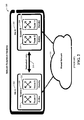
- Figure 1 depicts a prior art system providing a network application at two different geographical sites
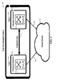
- Figure 2 depicts a prior art system providing a redundant network application at two different geographical sites
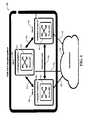
- Figure 3 depicts a dual-site entangled system for distributing network applications, with a single administrative location, among a pair of geographical sites;
- Figure 4 depicts a multi-site entangled system for distributing network applications, with a single administrative location, among a plurality of geographical sites;
- Figure 5 depicts a dual-site entangled system for distributing network applications, with a single administrative location, among a pair of geographical sites and including traffic distribution components for optimizing utilization and load balancing;
- Figure 6 depicts a multi-site entangled system for distributing network applications, with a single administrative location, among a plurality of geographical sites and a catastrophic failure of one of the entangled systems;
- Figure 7 depicts a dual-site entangled system for distributing network applications, with a single administrative location, among a pair of geographical sites, including a single-stage non-blocking fabric architecture for interconnecting the entangled systems;
- Figure 8 depicts a dual-site entangled system for distributing network applications, with a single administrative location, among a pair of geographical sites, including a three-stage folded Clos non-blocking fabric architecture for interconnecting the entangled systems;
- Figure 9 depicts a multi-site entangled system for distributing network applications, with a single administrative location, among a multiplicity of geographical sites, including a three-stage folded Clos non-blocking fabric architecture for interconnecting the entangled systems;
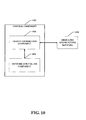
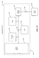
- Figure 10 depicts the control component of a multi-site entangled system for distributing network applications, with a single administrative location, including a traffic distribution component and a network site failure component;
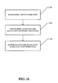
- Figure 11 depicts a method of implementing a multi-site entangled system, with a single administrative location, for distributing network applications
- Figure 12 depicts an exemplary computing device for implementing a multi-site entangled system, with a single administrative location, for distributing network applications.
- FIG. 1 a diagram 100 of a prior art method of providing a network application 110, 112 on two different geographical sites 102, 104 is illustrated and will provide a context for describing the exemplary embodiments provided herein.
- the prior art method includes site A 102 and site B 104 as two geographically distinct sites with system A 106 operating on site A 102 and system B 108 operating on site B 104. Further, the prior art method depicts a network application, router A 110, provisioned and operating on system A 106 and another copy of an identical network application, router B 112, operating on system B 108.
- site A 102 and site B 104 are communicatively connected by the shared network 114.
- the network router application running on site A 102 and the network router application running on site B 104 are identical but they must be provisioned, managed and maintained independently at the two different geographical sites, site A 102 and site B 104.
- all communications between the systems and network applications on site A 102 and site B 104 must be sent through the shared network 114. Further, there is not any capability to distribute access among router A 110 and router B 112.
- FIG. 2 a prior art embodiment of a network system for providing a redundant network application 200, including site A 202 and site B 204 positioned in different geographical locations, system A 206 located on site A 202 and system B 208 located on site B 204, active router A 210 and standby router B 212 operational on system A 206, active router B 214 and standby router A 216 operational on system B 208, with system A 206 and system B 208 communicatively connected by a dedicated link 218 and a shared network 220.
- standby router B 212 and standby router A 216 do not exist as physically separate entities, they are unused capacity of router B 214 and router A 210, respectively, overdesigned to provide the ability to support the others capacity should a catastrophic failure of one or the other occur.
- the dedicated link 218 is operational only to indicate a failure to one system of the other system and accordingly when to provide the redundant support.
- the one or more links interconnecting the redundant systems are typically used for user and system state information synchronization between the redundant systems.
- a dedicated link 218 is needed.
- multi-site entangled systems operating as a single system distributed geographically across different sites.
- the exemplary embodiment network applications physically exist on the different geographical sites but the provisioning, management and maintenance of the network applications is performed at a centralized location for each network application.
- the partitioning of a network application across multiple sites could be based, for example, on processing capacity considerations or client utilization location.
- a client request received at one entangled system site could be forwarded to and processed by another entangled system site based on the distribution policy defined for the network application.
- a catastrophic failure by one of the entangled sites can be used to limit the impact of the failure.
- a catastrophic failure of one of the entangled system sites would result in the loss of only the capacity of that site with respect to the overall capacity of the entangled system.
- the entangled sites must be interconnected with a dedicated link as previously described.
- the dedicated link must be efficient and have characteristics such as minimal latency between the entangled nodes, minimal jitter between the entangled nodes and minimal energy consumption i.e. the entangled system nodes should behave as if they are located at the same geographical site.
- An implication of this requirement is that the interconnection should allow non-blocking communications between the entangled nodes.
- the dedicated link is a requirement based on a quality of service of the communication links and therefore the dedicated link can be either a physically separate dedicated link or a logically separate dedicated link on a shared communication link meeting the same requirements provided by a physically separate dedicated link.
- an exemplary embodiment 300 of a dual-site entangled system is depicted, including a site A 302 containing entangled system A 306 wherein network application router AB 310 is operational, a site B 304 containing entangled system B 308 wherein network application router AB 312 is operational, a dedicated link 314 communicatively connecting site A 302 and site B 304, and a shared network 316 communicatively connected to entangled system A 306 by network link 318 and to entangled system B 308 by network link 320.
- the network application, router AB 310, 312 represents the same application running on the two geographically different systems but will behave as a single network application distributed between the two sites.
- the two network applications 310, 312 are provisioned, managed and maintained from a single location and use the dedicated link 314 as the control lines between the entangled systems.
- dedicated link 314 is a different communication network than network links 318, 320.
- FIG. 4 an exemplary embodiment of a multi-site entangled system 400 connected to a shared network 426 is depicted, including site A 402 containing entangled system A 408 wherein network application router ABC 414 is operational, site B 404 containing entangled system B 410 wherein network application router ABC 416 is operational, site C 406 containing entangled system C 412 wherein network application router ABC 418 is operational, dedicated link 420 communicatively connecting site A 402 to site B 404, dedicated link 422 communicatively connecting site A 402 to site C 406, dedicated link 424 communicatively connecting site B 404 to site C 406 and shared network 426 communicatively connected to entangled system A 408 by network link 428, to entangled system B 410 by network link 430 and to entangled system C 412 by network link 432.
- entangled system A 408 entangled system B 410 and entangled system C 412 are each nodes on shared network 426 by way of network links 428, 430 and 432 respectively, dedicated links 420, 422, 424 are separate communication links from each other and from shared network 426.
- the exemplary embodiment illustrates that the network application router ABC 414, 416, 418 is operational on each entangled system, as depicted in the dual entangled exemplary embodiment of figure 3 , but extended to each entangled system included in the multi-site entangled system.
- a large number of entangled systems and their associated network applications can be added to the multi-site entangled system, limited only by the requirements of the dedicated links for communication between the entangled systems.
- a multi-site entangled system allows for the distribution of a network application across multiple sites. The network application partitioning of the exemplary embodiment between multiple sites therefore could be based on data processing capacity or data distribution considerations.
- a request received at one of the entangled systems can be processed on the entangled system originally receiving the request or forwarded to another entangled system for processing based on the distribution policy associated with the particular network application. It should be noted in the exemplary embodiment that different network applications can have different distribution policies allowing for multi-faceted balancing of network resources and services.
- an exemplary embodiment 500 of a dual-site entangled system is depicted, including a site A 502 containing entangled system A 506 wherein network application router AB 510 is operational, a site B 504 containing entangled system B 508 wherein network application router AB 512 is operational, a dedicated link 514 communicatively connecting site A 502 and site B 504, a traffic distribution component 516 associated with entangled system A 506 and a traffic distribution component 518 associated with entangled system B 508. It should be noted in the exemplary embodiment that a distribution mechanism in each entangled system provides for properly redirecting communication traffic between all the entangled systems in an efficient and adaptable manner.
- FIG. 6 an exemplary embodiment of a multi-site entangled system 600 connected to a shared network 626 is depicted, including site A 602 containing entangled system A 608 wherein network application router ABC 614 is operational, site B 604 containing entangled system B 610 wherein network application router ABC 616 is operational, site C 606 containing entangled system C 612 wherein network application router ABC 618 is operational, dedicated link 620 communicatively connecting site A 602 to site B 604, dedicated link 622 communicatively connecting site A 602 to site C 606, dedicated link 624 communicatively connecting site B 604 to site C 606 and shared network 626 communicatively connected to entangled system A 608 by network link 628, to entangled system B 610 by network link 630 and to entangled system C 612 by network link 632.
- network application routers ABC 614, 616, 618 are initially evenly distributed between entangled systems A 608, B 610 and C 612 with each network application router ABC 614, 616, 618 handling one-third of the demand for the service.
- entangled system C 612 has a catastrophic failure and router ABC 618 is lost to the multi-site entangled system 600.
- the remaining entangled systems, entangled system A 608 and entangled system B 610 become aware of the failure of entangled system C 612 and network application router ABC 614, 616 can provide the additional capacity required based on the loss of network application router ABC 618.
- the failure of one site of an entangled system will result in only the loss of the failed system capacity, assuming each entangled system represents the same capacity. As illustrated in the multi-site entangled system 600, only one-third of the multi-site entangled system 600 capacity is lost with the failure of entangled system C 612. For example, a failure of one of the systems of an entangled system 600 results in a graceful degradation of service for the entire entangled system 600. In the exemplary embodiment, a graceful degradation implies that the entangled system 600 may lose a portion of the traffic capacity based on the current loading of the entire entangled system 600.
- a network configuration requirement of a hot standby is accomplished by distributing active and standby capacity across the entangled sites of the multi-site entangled system 600. It should be noted in the exemplary embodiment that based on the level of redundancy required, permanent and transient data, as well as some processing functions, may require synchronization between the systems of an entangled system 600.
- FIG. 7 an exemplary embodiment of a dual-site entangled system 700 is depicted, including site A 702 containing a single-stage fabric switch 706, site B 704 containing a single-stage fabric switch 708 and the dedicated optical links 734 and 736 connecting site A 702 to site B 704.
- site A 702 the fabric adapter bridges (FAB) 710, 712 acts as a fabric adaption layer between the entangled system's processing components 718, 720 and the core fabric element bridges (FEB) 726, 728 hardware.
- FAB fabric adapter bridges
- the FAB components 710, 712 are optional, meaning the processing components 718, 720 can be directly connected to the FEBs 726, 728 if adaptation is not required.
- the FEB 714, 716 acts as a fabric adaptation layer between the entangled system's processing components 722, 724 and the core FEB 730, 732 hardware.
- the FEBs are responsible for switching information between the entangled system's processing components. Further, it should be noted in the exemplary embodiment that depending on the technology selected for interconnecting the entangled systems with dedicated links, the characteristics of the switch fabric can differ in terms of bandwidth, latency, energy, efficiency, reachability, congestion management, quality of service (QoS), etc.
- the sites in order for the individual systems to act as a single distributed system, the sites should be interconnected extremely efficiently.
- the technology employed to connect the sites of the exemplary embodiment should focus on minimizing the communication latency between the nodes, minimizing the jitter between the links and the energy consumption of the entangled system so the individual systems can behave as if they are located on a single site.
- An implication of these characteristics is that the interconnection should allow non-blocking communications between the sites.
- each FEB is connected to the FABs on the local site and the FEBs on the remote site.
- FEB 726 on site A 702 is connected to local FABs 710, 712 and to FEBs 730, 732 on site B 704.
- each FEB can connect to a maximum of 64 FABs on their local site because of the necessity of connecting to the N FEBs on the associated remote site.
- the preferred embodiments use dedicated links to interconnect the entangled systems, it would be possible to interconnect the systems without dedicated links if the characteristics for latency, jitter and non-blocking communications are fulfilled, providing for a guaranteed Quality of Service for these links.
- Exemplary embodiment interconnection strategies based on optical technologies such as Single-Mode Fiber (SMF)/Wavelength-Division Multiplexing (WDM) can be used for a multi-site entangled system allowing a large bandwidth between the sites with low latency and high energy efficiency over long distances.
- SMF Single-Mode Fiber
- WDM Widelength-Division Multiplexing
- interconnecting multiple sites to create a multi-site entangled system allows to envision specific switch fabric architectures and, depending on whether a single-stage or a three-stage folded-Clos switch architecture is used, different FABs and FEBs interconnections can be optimally applicable.
- dual site entangled system 700 providing the characteristic non-blocking bandwidth capacity, each FEB should balance its bandwidth capacity between the processor blades and the FEB located on the remote site. Accomplishing this balance in the exemplary embodiment is characterized by a FEB of each plane on one site interconnected to a FEB of each plane on another site.
- the fabric architecture can be implemented as a single-stage fabric as illustrated in FIG. 7 or as a multi-stage fabric such as the three-stage Clos fabric illustrated in FIG. 8 .
- a multi-plane concept exists wherein multiple instances of a fabric architecture e.g. single-stage and three-stage Clos are parallelized high availability and high bandwidth solutions.
- exemplary embodiment 800 of a dual-site entangled system interconnected by a three-stage folded Clos architecture includes site A 802 containing a multi-plane three-stage folded-Clos fabric architecture 806, site B 804 containing a multi-plane three-stage folded-Clos fabric architecture 808 and the dedicated optical links 834, 836, 838, 840 connecting site A 802 to site B 804.
- the fabric adapter bridge (FAB) 810, 812 acts as a fabric adaption layer between the entangled system's processing components 818, 820 and the core fabric element bridge (FEB) 826, 828 hardware.
- the FAB 814, 816 acts a fabric adaption layer between the entangled system's processing components 822, 824 and the core FEBs (per plane) 830, 832 hardware.
- the sites are interconnected by dedicated optical links 834, 836, 838, 840 between fabric planes.
- non-blocking bandwidth capacity is provided by each second-stage FEB balancing its bandwidth capacity between the first/third stage FEBs, towards the processor blades and the second stage FEB located on the other entangled site.
- the 8192 available processor blades are distributed between the two sites such that every second-stage FEB of each plane on one entangled site is interconnected to a second stage FEB of a plane on the other entangled site.
- exemplary embodiment 900 of a multi-site entangled system with a "Valiant" load-balanced network topology interconnecting the entangled sites is depicted.
- exemplary embodiment 900 includes entangled site A 902 containing a multi-plane three-stage folded-Clos fabric architecture 916, entangled site B 904 containing a multi-plane three-stage folded-Clos fabric architecture 918 and the Valiant topology network interconnecting entangled sites A 902, B 904, C 906, D 908, E 910, F 912 and G 914.
- the fabric adapter bridge (FAB) 920, 922 acts as a fabric adaption layer between the entangled system's processing components and the core fabric element bridge (FEB) 928, 930 hardware.
- the FAB 924, 926 acts a fabric adaption layer between the entangled systems processing components and the core FEB 932, 934 hardware.
- entangled sites C 906, D 908, E 910, F 912 and G 914 have similar designs as entangled sites A 902 and B 904.
- the second-stage FEBs of each entangled site are connected to the FEBs of other entangled sites with each second-stage FEB distributing its dedicated links between all other entangled sites. Further in the exemplary embodiment, based on an even processing capability among the entangled sites, the dedicated links are evenly distributed among the entangled sites.
- the exemplary embodiment network topology allows not only for direct communication between any two entangled sites, entangled site A and entangled site B for example, on the dedicated network connecting the two entangled sites but also through other entangled sites, also directly connected by the dedicated network, that are asked to forward packets between the two entangled sites A and B.
- FIG. 10 an exemplary embodiment 1000 of a control component 1002 interacting with a dedicated non-blocking communication network is depicted.
- the exemplary embodiment 1000 includes a traffic distribution component 1004 and a network site failure component 1006. It should be noted that although the control component 1002 is illustrated as separate from the dedicated non-blocking communication network 1008, the control component 1002 can be part of the dedicated non-blocking communication network 1008.
- the traffic distribution component 1004 provides the capability to distribute a network application's workload throughout the entangled system based on a distribution policy associated with the network application.
- the traffic distribution component can direct a particular packet's processing from the entangled site receiving the packet to another entangled site based on a entangled site resource analysis and return the results associated with the packet to the entangled site originally receiving the packet for return to the client.
- the network site failure component 1006 provides the capability to determine that a particular entangled site is no longer responsive. Under the circumstances of an entangled site failure, the network site failure component 1006 notifies the traffic distribution component 1004 of the failure and the traffic distribution component 1004 can rebalance the particular network application workload based on a new entangled system resource analysis. It should be noted that a similar analysis is performed for each network application associated with a failed entangled site.
- FIG. 11 an exemplary method embodiment 1100 based on a multi-site entangled system is depicted.
- the network sites already connected by a shared network, are interconnected with a dedicated non-blocking communication network.
- the exemplary embodiment network topology of the dedicated non-blocking communication network can vary based on the number of sites interconnected and the geographical distance between the sites. Examples of the internal fabric network topologies include, but are not limited to single-stage fabric switch architecture and three-stage folded Clos architecture.
- network applications are provisioned on as many sites as required based, for example, on entangled site resources and network application utilization.
- management of the network application is performed. For example, network application configuration and tuning is provided to match the network application to the computing environment at any given entangled system site.
- maintenance of the distributed network application is performed. For example, if a particular entangled site would require a database compaction then that site can be instructed to compact the database for the particular application.
- the network application workload is distributed around the entangled sites of the multi-site entangled system.
- a distribution policy associated with a network application and implemented by the dedicated non-blocking communication network, specifies which site will process which packets. It should be noted in the exemplary embodiment that the network applications of a multi-site entangled system can be managed from a single location and appears as a single application distributed throughout the multi-site entangled system.
- FIG. 12 illustrates an example of a suitable computing system environment 1200 in which the claimed subject matter can be implemented, although as made clear above, the computing system environment 1200 is only one example of a suitable computing environment for an exemplary embodiment and is not intended to suggest any limitation as to the scope of use or functionality of the claimed subject matter. Further, the computing environment 1200 is not intended to suggest any dependency or requirement relating to the claimed subject matter and any one or combination of components illustrated in the example computing environment 1200.
- an example of a device for implementing the previously described innovation includes a general purpose computing device in the form of a computer 1210.
- Components of computer 1210 can include, but are not limited to, a processing unit 1220, a system memory 1230, and a system bus 1290 that couples various system components including the system memory to the processing unit 1220.
- the system bus 1290 can be any of several types of bus structures including a memory bus or memory controller, a peripheral bus, and a local bus using any of a variety of bus architectures.
- Computer 1210 can include a variety of computer readable media.
- Computer readable media can be any available media that can be accessed by computer 1210.
- Computer readable media can comprise computer storage media and communication media.
- Computer storage media includes volatile and nonvolatile as well as removable and non-removable media implemented in any method or technology for storage of information such as computer readable instructions, data structures, program modules or other data.
- Computer storage media includes, but is not limited to, RAM, ROM, EEPROM, flash memory or other memory technology, CDROM, digital versatile disks (DVD) or other optical disk storage, magnetic cassettes, magnetic tape, magnetic disk storage or other magnetic storage devices, or any other medium which can be used to store the desired information and which can be accessed by computer 1210.
- Communication media can embody computer readable instructions, data structures, program modules or other data in a modulated data signal such as a carrier wave or other transport mechanism and can include any suitable information delivery media.
- the system memory 1230 can include computer storage media in the form of volatile and/or nonvolatile memory such as read only memory (ROM) and/or random access memory (RAM).
- ROM read only memory
- RAM random access memory
- a basic input/output system (BIOS) containing the basic routines that help to transfer information between elements within computer 1210, such as during start-up, can be stored in memory 1230.
- BIOS basic input/output system
- Memory 1230 can also contain data and/or program modules that are immediately accessible to and/or presently being operated on by processing unit 1220.
- memory 1230 can also include an operating system, application programs, other program modules, and program data.
- the computer 1210 can also include other removable/non-removable and volatile/nonvolatile computer storage media.
- computer 1210 can include a hard disk drive that reads from or writes to non-removable, nonvolatile magnetic media, a magnetic disk drive that reads from or writes to a removable, nonvolatile magnetic disk, and/or an optical disk drive that reads from or writes to a removable, nonvolatile optical disk, such as a CD-ROM or other optical media.
- Other removable/non-removable, volatile/nonvolatile computer storage media that can be used in the exemplary operating environment include, but are not limited to, magnetic tape cassettes, flash memory cards, digital versatile disks, digital video tape, solid state RAM, solid state ROM and the like.
- a hard disk drive can be connected to the system bus 1290 through a non-removable memory interface such as an interface, and a magnetic disk drive or optical disk drive can be connected to the system bus 1290 by a removable memory interface, such as an interface.
- a user can enter commands and information into the computer 1210 through input devices such as a keyboard or a pointing device such as a mouse, trackball, touch pad, and/or other pointing device.
- Other input devices can include a microphone, joystick, game pad, satellite dish, scanner, or similar devices.
- These and/or other input devices can be connected to the processing unit 1220 through user input 1240 and associated interface(s) that are coupled to the system bus 1290, but can be connected by other interface and bus structures, such as a parallel port, game port or a universal serial bus (USB).
- USB universal serial bus
- a graphics subsystem can also be connected to the system bus 1290.
- a monitor or other type of display device can be connected to the system bus 1290 through an interface, such as output interface 1250, which can in turn communicate with video memory.
- computers can also include other peripheral output devices, such as speakers and/or printing devices, which can also be connected through output interface 1250.
- the computer 1210 can operate in a networked or distributed environment using logical connections to one or more other remote computers, such as remote server 1270, which can in turn have media capabilities different from device 1210.
- the remote server 1270 can be a personal computer, a server, a router, a network PC, a peer device or other common network node, and/or any other remote media consumption or transmission device, and can include any or all of the elements described above relative to the computer 1210.
- the logical connections depicted in FIG. 12 include a network 1280, such as a local area network (LAN) or a wide area network (WAN), but can also include other networks/buses.
- LAN local area network
- WAN wide area network
- the computer 1210 When used in a LAN networking environment, the computer 1210 is connected to the LAN 1280 through a network interface 1260 or adapter. When used in a WAN networking environment, the computer 1210 can include a communications component, such as a modem, or other means for establishing communications over a WAN, such as the Internet.
- a communications component such as a modem, which can be internal or external, can be connected to the system bus 1290 through the user input interface at input 1240 and/or other appropriate mechanism.
- program modules depicted relative to the computer 1210, or portions thereof, can be stored in a remote memory storage device. It should be noted that the network connections shown and described are exemplary and other means of establishing a communications link between the computers can be used.
- a component may be, but is not limited to being, a process running on a processor, a processor, an object, an executable, a thread of execution, a program and a computing device.
- a component may be, but is not limited to being, a process running on a processor, a processor, an object, an executable, a thread of execution, a program and a computing device.
- both an application running on a computing device and the computing device can be components.
- One or more components can reside within a process and/or thread of execution and a component can be localized on one computing device and/or distributed between two or more computing devices, and/or communicatively connected modules. Further, it should be noted that as used in this application, terms such as "system user,” “user,” and similar terms are intended to refer to the person operating the computing device referenced above.
- the term to "infer” or “inference” refer generally to the process of reasoning about or inferring states of the system, environment, user, and/or intent from a set of observations captured from events and/or data. Captured events and data can include user data, device data, environment data, behavior data, application data, implicit and explicit data, etc. Inference can be employed to identify a specific context or action, or can generate a probability distribution over states, for example. The inference can be probabilistic in that the computation of a probability distribution over states of interest based on a consideration of data and events. Inference can also refer to techniques employed for composing higher-level events from a set of events and/or data. Such inference results in the construction of new events or actions from a set of observed events and/or stored event data, whether or not the events are correlated in close temporal proximity, and whether the events and data come from one or several event and data sources.
Landscapes
- Engineering & Computer Science (AREA)
- Computer Networks & Wireless Communication (AREA)
- Signal Processing (AREA)
- Computer Security & Cryptography (AREA)
- Data Exchanges In Wide-Area Networks (AREA)
Applications Claiming Priority (1)
| Application Number | Priority Date | Filing Date | Title |
|---|---|---|---|
| US13/167,398 US9246994B2 (en) | 2011-06-23 | 2011-06-23 | Method and system for distributing a network application among a plurality of network sites on a shared network |
Publications (2)
| Publication Number | Publication Date |
|---|---|
| EP2575325A2 true EP2575325A2 (fr) | 2013-04-03 |
| EP2575325A3 EP2575325A3 (fr) | 2014-10-22 |
Family
ID=46796244
Family Applications (1)
| Application Number | Title | Priority Date | Filing Date |
|---|---|---|---|
| EP12006031.4A Withdrawn EP2575325A3 (fr) | 2011-06-23 | 2012-08-23 | Procédé et système permettant de distribuer une application de réseau parmi une pluralité de sites de réseau sur un réseau partagé |
Country Status (2)
| Country | Link |
|---|---|
| US (1) | US9246994B2 (fr) |
| EP (1) | EP2575325A3 (fr) |
Families Citing this family (4)
| Publication number | Priority date | Publication date | Assignee | Title |
|---|---|---|---|---|
| US20180152525A1 (en) | 2016-11-29 | 2018-05-31 | International Business Machines Corporation | System and method for attribute based device and service discovery |
| CN109039698A (zh) * | 2018-06-20 | 2018-12-18 | 南京邮电大学 | 工业互联网智能服务处理方法、可读存储介质、终端 |
| CN108924196B (zh) * | 2018-06-20 | 2021-01-19 | 南京邮电大学 | 工业互联网绿色能源管理系统 |
| US10855757B2 (en) | 2018-12-19 | 2020-12-01 | At&T Intellectual Property I, L.P. | High availability and high utilization cloud data center architecture for supporting telecommunications services |
Family Cites Families (24)
| Publication number | Priority date | Publication date | Assignee | Title |
|---|---|---|---|---|
| US5321813A (en) * | 1991-05-01 | 1994-06-14 | Teradata Corporation | Reconfigurable, fault tolerant, multistage interconnect network and protocol |
| US20020152305A1 (en) | 2000-03-03 | 2002-10-17 | Jackson Gregory J. | Systems and methods for resource utilization analysis in information management environments |
| GB0007552D0 (en) * | 2000-03-28 | 2000-05-17 | Iltron Limited | A fully reconfigurable regenerative optical add-drop multiplexer |
| US6965592B2 (en) | 2001-01-24 | 2005-11-15 | Tekelec | Distributed signaling system 7 (SS7) message routing gateway |
| US7937551B2 (en) | 2003-01-21 | 2011-05-03 | Dell Products L.P. | Storage systems having differentiated storage pools |
| US20040210623A1 (en) | 2003-03-06 | 2004-10-21 | Aamer Hydrie | Virtual network topology generation |
| US7397796B1 (en) * | 2003-08-21 | 2008-07-08 | Smiljanic Aleksandra | Load balancing algorithms in non-blocking multistage packet switches |
| US7643468B1 (en) | 2004-10-28 | 2010-01-05 | Cisco Technology, Inc. | Data-center network architecture |
| US20070121499A1 (en) * | 2005-11-28 | 2007-05-31 | Subhasis Pal | Method of and system for physically distributed, logically shared, and data slice-synchronized shared memory switching |
| US7720061B1 (en) | 2006-08-18 | 2010-05-18 | Juniper Networks, Inc. | Distributed solution for managing periodic communications in a multi-chassis routing system |
| CN101669317B (zh) * | 2006-12-20 | 2013-07-10 | 波拉替斯光子学公司 | 网络故障检测及保护切换 |
| US8484656B2 (en) * | 2007-03-12 | 2013-07-09 | Citrix Systems, Inc. | Systems and methods for providing global server load balancing of heterogeneous devices |
| US7843908B2 (en) * | 2007-06-08 | 2010-11-30 | Roberto Rojas-Cessa | Scalable two-stage Clos-networking switch and module-first matching |
| US8325749B2 (en) * | 2008-12-24 | 2012-12-04 | Juniper Networks, Inc. | Methods and apparatus for transmission of groups of cells via a switch fabric |
| US7961734B2 (en) * | 2008-09-30 | 2011-06-14 | Juniper Networks, Inc. | Methods and apparatus related to packet classification associated with a multi-stage switch |
| US8639813B2 (en) * | 2008-11-25 | 2014-01-28 | Citrix Systems, Inc. | Systems and methods for GSLB based on SSL VPN users |
| US8254255B2 (en) * | 2008-12-29 | 2012-08-28 | Juniper Networks, Inc. | Flow-control in a switch fabric |
| US8532481B2 (en) * | 2009-01-28 | 2013-09-10 | Tellabs Operations, Inc. | Dual fault tolerant optical networking with fast protection performance |
| US8446906B2 (en) * | 2009-07-01 | 2013-05-21 | Infinera Corporation | Providing access to client overhead while transparently transmitting the client signal |
| US20110085557A1 (en) * | 2009-10-08 | 2011-04-14 | Brocade Communications Systems, Inc. | Partitioning of Switches and Fabrics into Logical Switches and Fabrics |
| US8578191B2 (en) * | 2010-06-10 | 2013-11-05 | Juniper Networks, Inc. | Dynamic fabric plane allocation for power savings |
| US20120102506A1 (en) * | 2010-10-20 | 2012-04-26 | Microsoft Corporation | Web service patterns for globally distributed service fabric |
| US10033585B2 (en) * | 2010-12-15 | 2018-07-24 | Juniper Networks, Inc. | Methods and apparatus related to a switch fabric system having a multi-hop distributed control plane and a single-hop data plane |
| US8631099B2 (en) * | 2011-05-27 | 2014-01-14 | Red Hat, Inc. | Systems and methods for cloud deployment engine for selective workload migration or federation based on workload conditions |
-
2011
- 2011-06-23 US US13/167,398 patent/US9246994B2/en active Active
-
2012
- 2012-08-23 EP EP12006031.4A patent/EP2575325A3/fr not_active Withdrawn
Non-Patent Citations (1)
| Title |
|---|
| None |
Also Published As
| Publication number | Publication date |
|---|---|
| EP2575325A3 (fr) | 2014-10-22 |
| US9246994B2 (en) | 2016-01-26 |
| US20130039657A1 (en) | 2013-02-14 |
Similar Documents
| Publication | Publication Date | Title |
|---|---|---|
| US9325619B2 (en) | System and method for using virtual lanes to alleviate congestion in a fat-tree topology | |
| US6597956B1 (en) | Method and apparatus for controlling an extensible computing system | |
| Blial et al. | An overview on SDN architectures with multiple controllers | |
| US10630570B2 (en) | System and method for supporting well defined subnet topology in a middleware machine environment | |
| US7146233B2 (en) | Request queue management | |
| EP2888865B1 (fr) | Système et procédé pour la prise en charge d'une communication en réseau hautement disponible (ha), dans un environnement de machine de couche logicielle intermédiaire | |
| Thean et al. | Container-based MQTT broker cluster for edge computing | |
| US10164845B2 (en) | Network service aware routers, and applications thereof | |
| CN102007736A (zh) | Wdm网状网络中的保护共享的方法 | |
| Couto et al. | Server placement with shared backups for disaster-resilient clouds | |
| CN113709220B (zh) | 虚拟负载均衡器的高可用实现方法、系统及电子设备 | |
| US7783786B1 (en) | Replicated service architecture | |
| US9246994B2 (en) | Method and system for distributing a network application among a plurality of network sites on a shared network | |
| WO2022245479A1 (fr) | Cellule de courtier pour système de messagerie distribué | |
| Develder et al. | Resilient network dimensioning for optical grid/clouds using relocation | |
| US8625407B2 (en) | Highly available virtual packet network device | |
| US11245664B2 (en) | Conveying network-address-translation (NAT) rules in a network | |
| Aglan et al. | Reliability and scalability in SDN networks | |
| US8964596B1 (en) | Network service aware routers, and applications thereof | |
| Askari et al. | Protection strategies for dynamic VNF placement and service chaining | |
| Pashkov et al. | On high availability distributed control plane for software-defined networks | |
| US20130103854A1 (en) | Routing network traffic | |
| Tzeng et al. | An integrated multi-controller management framework for highly reliable software defined networking | |
| KR20150123400A (ko) | 클러스터링 알고리즘 중심의 의료정보시스템 메커니즘 설계 방법 | |
| CN116938693A (zh) | 用户迁移的方法、装置、系统及存储介质 |
Legal Events
| Date | Code | Title | Description |
|---|---|---|---|
| PUAI | Public reference made under article 153(3) epc to a published international application that has entered the european phase |
Free format text: ORIGINAL CODE: 0009012 |
|
| AK | Designated contracting states |
Kind code of ref document: A2 Designated state(s): AL AT BE BG CH CY CZ DE DK EE ES FI FR GB GR HR HU IE IS IT LI LT LU LV MC MK MT NL NO PL PT RO RS SE SI SK SM TR |
|
| AX | Request for extension of the european patent |
Extension state: BA ME |
|
| PUAL | Search report despatched |
Free format text: ORIGINAL CODE: 0009013 |
|
| AK | Designated contracting states |
Kind code of ref document: A3 Designated state(s): AL AT BE BG CH CY CZ DE DK EE ES FI FR GB GR HR HU IE IS IT LI LT LU LV MC MK MT NL NO PL PT RO RS SE SI SK SM TR |
|
| AX | Request for extension of the european patent |
Extension state: BA ME |
|
| RIC1 | Information provided on ipc code assigned before grant |
Ipc: H04L 29/14 20060101ALI20140917BHEP Ipc: H04L 29/08 20060101AFI20140917BHEP Ipc: G06F 9/50 20060101ALI20140917BHEP |
|
| 17P | Request for examination filed |
Effective date: 20150324 |
|
| RBV | Designated contracting states (corrected) |
Designated state(s): AL AT BE BG CH CY CZ DE DK EE ES FI FR GB GR HR HU IE IS IT LI LT LU LV MC MK MT NL NO PL PT RO RS SE SI SK SM TR |
|
| STAA | Information on the status of an ep patent application or granted ep patent |
Free format text: STATUS: THE APPLICATION HAS BEEN WITHDRAWN |
|
| 18W | Application withdrawn |
Effective date: 20161222 |