EP2575223A2 - An embedment box for hollow floor structure as well as a method for the mounting of the same - Google Patents
An embedment box for hollow floor structure as well as a method for the mounting of the same Download PDFInfo
- Publication number
- EP2575223A2 EP2575223A2 EP12186421A EP12186421A EP2575223A2 EP 2575223 A2 EP2575223 A2 EP 2575223A2 EP 12186421 A EP12186421 A EP 12186421A EP 12186421 A EP12186421 A EP 12186421A EP 2575223 A2 EP2575223 A2 EP 2575223A2
- Authority
- EP
- European Patent Office
- Prior art keywords
- box
- embedment
- floor structure
- embedment box
- hollow floor
- Prior art date
- Legal status (The legal status is an assumption and is not a legal conclusion. Google has not performed a legal analysis and makes no representation as to the accuracy of the status listed.)
- Granted
Links
- 238000000034 method Methods 0.000 title claims abstract description 13
- 239000011796 hollow space material Substances 0.000 claims description 7
- GNFTZDOKVXKIBK-UHFFFAOYSA-N 3-(2-methoxyethoxy)benzohydrazide Chemical compound COCCOC1=CC=CC(C(=O)NN)=C1 GNFTZDOKVXKIBK-UHFFFAOYSA-N 0.000 claims description 2
- 238000009434 installation Methods 0.000 description 6
- 238000005192 partition Methods 0.000 description 4
- 238000009408 flooring Methods 0.000 description 3
- 230000000295 complement effect Effects 0.000 description 1
- 230000001419 dependent effect Effects 0.000 description 1
- 238000009826 distribution Methods 0.000 description 1
- 238000010616 electrical installation Methods 0.000 description 1
- 230000002349 favourable effect Effects 0.000 description 1
- 239000006260 foam Substances 0.000 description 1
- 238000004519 manufacturing process Methods 0.000 description 1
- 239000000463 material Substances 0.000 description 1
- 239000011490 mineral wool Substances 0.000 description 1
- 238000012986 modification Methods 0.000 description 1
- 230000004048 modification Effects 0.000 description 1
- 238000003825 pressing Methods 0.000 description 1
- 230000001681 protective effect Effects 0.000 description 1
- 230000002787 reinforcement Effects 0.000 description 1
Images


Classifications
-
- H—ELECTRICITY
- H02—GENERATION; CONVERSION OR DISTRIBUTION OF ELECTRIC POWER
- H02G—INSTALLATION OF ELECTRIC CABLES OR LINES, OR OF COMBINED OPTICAL AND ELECTRIC CABLES OR LINES
- H02G3/00—Installations of electric cables or lines or protective tubing therefor in or on buildings, equivalent structures or vehicles
- H02G3/02—Details
- H02G3/08—Distribution boxes; Connection or junction boxes
- H02G3/18—Distribution boxes; Connection or junction boxes providing line outlets
- H02G3/185—Floor outlets and access cups
-
- H—ELECTRICITY
- H02—GENERATION; CONVERSION OR DISTRIBUTION OF ELECTRIC POWER
- H02G—INSTALLATION OF ELECTRIC CABLES OR LINES, OR OF COMBINED OPTICAL AND ELECTRIC CABLES OR LINES
- H02G3/00—Installations of electric cables or lines or protective tubing therefor in or on buildings, equivalent structures or vehicles
- H02G3/02—Details
- H02G3/08—Distribution boxes; Connection or junction boxes
- H02G3/12—Distribution boxes; Connection or junction boxes for flush mounting
-
- H—ELECTRICITY
- H02—GENERATION; CONVERSION OR DISTRIBUTION OF ELECTRIC POWER
- H02G—INSTALLATION OF ELECTRIC CABLES OR LINES, OR OF COMBINED OPTICAL AND ELECTRIC CABLES OR LINES
- H02G3/00—Installations of electric cables or lines or protective tubing therefor in or on buildings, equivalent structures or vehicles
- H02G3/02—Details
- H02G3/08—Distribution boxes; Connection or junction boxes
- H02G3/12—Distribution boxes; Connection or junction boxes for flush mounting
- H02G3/121—Distribution boxes; Connection or junction boxes for flush mounting in plain walls
-
- H—ELECTRICITY
- H02—GENERATION; CONVERSION OR DISTRIBUTION OF ELECTRIC POWER
- H02G—INSTALLATION OF ELECTRIC CABLES OR LINES, OR OF COMBINED OPTICAL AND ELECTRIC CABLES OR LINES
- H02G3/00—Installations of electric cables or lines or protective tubing therefor in or on buildings, equivalent structures or vehicles
- H02G3/02—Details
- H02G3/08—Distribution boxes; Connection or junction boxes
- H02G3/18—Distribution boxes; Connection or junction boxes providing line outlets
-
- H—ELECTRICITY
- H02—GENERATION; CONVERSION OR DISTRIBUTION OF ELECTRIC POWER
- H02G—INSTALLATION OF ELECTRIC CABLES OR LINES, OR OF COMBINED OPTICAL AND ELECTRIC CABLES OR LINES
- H02G3/00—Installations of electric cables or lines or protective tubing therefor in or on buildings, equivalent structures or vehicles
- H02G3/28—Installations of cables, lines, or separate protective tubing therefor in conduits or ducts pre-established in walls, ceilings or floors
- H02G3/283—Installations of cables, lines, or separate protective tubing therefor in conduits or ducts pre-established in walls, ceilings or floors in floors
-
- H—ELECTRICITY
- H02—GENERATION; CONVERSION OR DISTRIBUTION OF ELECTRIC POWER
- H02G—INSTALLATION OF ELECTRIC CABLES OR LINES, OR OF COMBINED OPTICAL AND ELECTRIC CABLES OR LINES
- H02G3/00—Installations of electric cables or lines or protective tubing therefor in or on buildings, equivalent structures or vehicles
- H02G3/36—Installations of cables or lines in walls, floors or ceilings
- H02G3/38—Installations of cables or lines in walls, floors or ceilings the cables or lines being installed in preestablished conduits or ducts
- H02G3/383—Installations of cables or lines in walls, floors or ceilings the cables or lines being installed in preestablished conduits or ducts in floors
-
- H—ELECTRICITY
- H02—GENERATION; CONVERSION OR DISTRIBUTION OF ELECTRIC POWER
- H02G—INSTALLATION OF ELECTRIC CABLES OR LINES, OR OF COMBINED OPTICAL AND ELECTRIC CABLES OR LINES
- H02G3/00—Installations of electric cables or lines or protective tubing therefor in or on buildings, equivalent structures or vehicles
- H02G3/36—Installations of cables or lines in walls, floors or ceilings
- H02G3/38—Installations of cables or lines in walls, floors or ceilings the cables or lines being installed in preestablished conduits or ducts
- H02G3/383—Installations of cables or lines in walls, floors or ceilings the cables or lines being installed in preestablished conduits or ducts in floors
- H02G3/385—Installations of cables or lines in walls, floors or ceilings the cables or lines being installed in preestablished conduits or ducts in floors in modular floors, e.g. access floors
Definitions
- the present invention relates to the area of the installation of electrically conducting cables in floor structures and particularly in hollow floor structures.
- HDF floor structures In the new production of blocks of offices, prefabricated hollow floor structures, so-called HDF floor structures, are often used for providing the different floor plans.
- the floor structures are delivered in lengths of up to 12 m having 4 to 6 longitudinal tubular hollow spaces, the floor structure is formed in such a way that no additional reinforcement of its strength is needed, which means that, in order to complete the floor, it is desired to apply as little self-levelling screed/concrete as possible, which means a layer from a few centimetres or more.
- the object of the present invention is to provide an embedment box of a hollow floor structure, which solves the above-mentioned problems by affording considerably more generous mounting volumes for the electrical installations than what previously has been the case.
- the object is further to provide a mounting device for an embedment box in such a hollow floor structure.
- the object is further to provide such a mounting device that gives the possibility of pre-setting the vertical level of the box in relation to the hollow floor structure.
- the invention is based on using the longitudinal channels in the hollow floor structure for the installation of floor boxes and also for the cabling in the longitudinal channels thereof, without, by this installation and cabling, altering the strength of the hollow floor structure.
- This is provided by mounting an embedment box in the hollow floor structure. Cabling in another direction than in the longitudinal channels of the floor structure may be carried out in partition walls or in false ceilings of the floor plan below.
- cablings may be effected transversely to the hollow space channels of the floor structure by the embedment box having connections for cabling ducts also on the upper side.
- the invention concerns an embedment box of a hollow floor structure, which box comprises a bottom wall, side walls, and end walls as well as at least one top wall, which walls limit the inner volume of the box. At least one of said walls is provided with a breakout opening in which a tube adapter is mounted for the connection of a wiring tube for wiring/cabling.
- the top wall is provided with an upper part through which the inner volume of the box can be reached. Furthermore, the width of the box is smaller than the width of a channel in the hollow floor structure.
- the embedment box is further provided with level-fixing means connectable to the hollow floor structure. These members allow an adjustment of the vertical position of the box in relation to the floor structure.
- the members may be of varying design such as angle-irons that have been attached to the surface of the floor structure or pressing devices that operate between the wall/walls of the embedment box and the channel walls of the inside of the floor structure. They may also be formed to operate between the bottom of the embedment box and the bottom of the inside of the channel of the floor structure. It is also feasible that the members may be formed as wire devices, which by a rotary motion provides a level regulation of the embedment box. All embodiments of the level-fixing means may, however, be adjusted for different vertical positions of the embedment box.
- the outside of some one of the walls of the embedment box is provided with at least one bracket attachment onto which an adjustable mounting bracket is mounted.
- the adjustability of the mounting bracket means that a fitter already upon the mounting of the box can adjust the same to an estimated final level of the finished concrete floor surface.
- This mounting may also be made for different installation alternatives of tubings, which optimizes the installation work considerably.
- the mounting bracket is rotatably and lockably connected to the bracket attachment. This rotatability further increases the installation alternatives by the fact that different vertical positions can be selected.
- the mounting bracket is formed as an L-shaped means having a first branch, provided with a position hole for the fastening to said bracket attachment, as well as a second branch, oriented 90° from the first branch and provided with at least one fixing hole for the fastening to the surface of the hollow floor structure.
- This angled design of the mounting bracket implies a very rigid clamping during an embedment procedure when the embedment box on no account must be dislodged from its position.
- the position hole of the first branch is formed as a slot having an extension in the direction of the first branch. This slot shape further increases the possibilities of more accurately determining the vertical position of the embedment box at the same time as four discrete positions can be selected by only one fixing screw.
- the fixing hole of the second branch is formed as a slot having an extension in the direction of the second branch. Also this slot shape makes it easier to select fastening place for a nail/screw/rivet/bolt in the concrete for the mounting bracket.
- the second branch is further provided with an additional one to four fixing holes, which are placed laterally displaced in the branch in relation to said position hole. Said additional fixing holes allow further fastening options or alternative fastening places for the mounting bracket against the concrete, which further increases the attachment possibilities.
- the walls of the box are provided with four bracket attachments each one of which provided with a mounted adjustable mounting bracket.
- the four bracket attachments are symmetrically placed in relation to the upper part of the box.
- a symmetrical placement of the brackets implies a favourable distribution of load upon the mounting of the entire embedment box.
- the upper part is rectangularly shaped, the bracket attachments being placed adjacent to the respective corners of the upper part.
- the placement of the brackets at the corners implies that the levelling into the horizontal position is facilitated.
- the upper part is provided with a levelling device.
- This device is a complement to the mounting brackets, which facilitates the fine adjustment to the horizontal position of the upper part and fine adjustment does not have to be made via the slots in the mounting bracket.
- the invention also concerns a method for the mounting of an embedment box according to the embodiments presented above in a hollow floor structure.
- the method concerns the following mounting steps:
- the mounting step c) is replaced by at least one adjustable mounting bracket being mounted onto the embedment box in a selected position for a coarse adjustment of the height of the embedment box in relation to the level of the finished concrete floor
- the mounting step g) is replaced by concrete being filled into the gap around the embedment box and up to a level corresponding to the finished concrete floor.
- some of the mounting steps a) to g) comprises that the level of the upper part of the embedment box is fine-adjusted. This fine adjustment is made either in the slots of the mounting brackets or by a separate levelling device. The fine adjustment provides a more accurate horizontal position of the embedment box and/or its upper part.
- Figure 1 shows a hollow floor structure 10 of concrete, which is provided with longitudinal hollow spaces in the form of channels 11. Between the channels 11, webs 12 are formed, which are the principal force-absorbing part of the hollow floor structure and therefore determine the strength of the floor structure.
- An embedment hole 13 is recessed in the surface 14 of the hollow floor structure 10 straight above one of the channels 11.
- an embedment box 15 is lowered and attached by means of at least one adjustable mounting bracket 16.
- the figure shows four identical mounting brackets, which all are mounted onto the embedment box in the same relative position.
- a wiring tube 171 is connected to the end wall of the embedment box 15 for wiring/cabling to the box.
- the wiring tube 171 extends through the channel 11 in the hollow floor structure 10 in which the embedment box 15 is mounted.
- second wiring tubes 172 may be connected to the embedment box 15 from the bottom wall thereof and thereby extend out through the bottom of the channel of the hollow floor structure.
- third wiring tubes 173 may be connected to the embedment box 15 from the top wall thereof and thereby extend upward and out through the embedment hole 13.
- different types of wiring tubes may be connected to different side walls of the embedment box and extend out through the hollow floor structure in several conceivable ways.
- the embedment box 15 is furthermore provided with an upper part 18 connected to the top wall of the embedment box 15.
- Figure 2 shows the proper embedment box 15, which is provided with a bottom wall 21, side walls 22, and end walls 23 as well as a top wall 24 on each side of the upper part 18 of the embedment box.
- the walls limit the inner volume 25 of the box, which can be reached via the upper part 18.
- the embedment box is provided with breakout openings 26 placed in the end wall 23 as well as in the top walls 24.
- the bottom wall may be provided with such breakout openings.
- the embedment box 15 is provided with four bracket attachments 27 symmetrically placed around the upper part 18.
- each one of which brackets is formed as an L-shaped means having a first branch 28, provided with a slot-shaped position hole 29 for the fastening to said bracket attachment 27, as well as a second branch 30, oriented 90° from the first branch and provided with at least one fixing hole 31 for the fastening to the surface of the hollow floor structure.
- the fixing hole 31 of the second branch 30 is formed as a slot having an extension in the direction of the second branch.
- the second branch is further provided with four additional fixing holes 32, which are placed laterally displaced as well as longitudinally displaced in the branch in relation to said slot-shaped fixing hole.
- the figure shows the first mounting bracket 161 in the position C and the second 162, the third 163, and the fourth mounting bracket 164 in the position A. Since the position hole is formed as a slot, naturally variable mounting positions are feasible.
- slots are to provide the first branch with two holes, suitably at a distance from each other of 25 mm in order to achieve the same discrete four positions. Both the slot and possible holes are centrally placed in the branch, oriented longitudinally. As is seen in the figure, the mounting brackets are fixed to the embedment box in their respective positions by means of a fixing screw.
- Figure 3 shows a longitudinal section through an embedment box 15 mounted in a hollow floor structure 10.
- the mounting brackets 16 of the embedment box have been mounted in one suitable position of the four discrete positions, i.e., the separated positions, wiring tubes 171, 173 having been mounted to a first tube adapter 310 in the breakout opening of an end wall as well as to a second tube adapter 320 in the breakout opening of a top wall in the embedment box 15.
- the embedment box 15 is lowered into the embedment hole 13, wherein it is anchored via the mounting brackets in the surface 14 of the hollow floor structure.
- the channel 11 of the hollow floor structure is sealed on both sides of the embedment box 15 by a homogeneous first pour stop 33 and a tube-penetrable second pour stop 34, which pour stops block flowing concrete from running out into the channel when the embedment hole 13 is filled with concrete up to the level of the surface 14 of the hollow floor structure.
- wiring tubes 173 are mounted to the embedment box to run on top of said surface 14, either parallel to the channels or at some angle to the same, for instance 90°, and therefore concrete should be filled up to or above the level of the tubes either in the same filling step or upon an extra filling-up step.
- the upper part 18 is variably adjustable by a levelling device 35.
- levelling of the upper part can be effected in the interval of 0-25 mm, wherein fine adjustment can be made variably into positions between said four discrete positions of the embedment box.
- the upper part 18 is levelled to a position wherein a replenishment of concrete can be made above the wiring tube 173 and on a level with the upper part.
- the same is provided with levelling in all four corners.
- Figure 4a shows a cross-section through a hollow floor structure 10 and an embedment box 15 mounted therein.
- the upper part 18 consists of a base part 41 and a top part 42, the figure showing that the top part has been levelled to a level that is situated above the surface 14 of the floor structure and the mounting brackets 16 by means of the levelling screws 43, 44. Since the embedment box 15 will contain electrical equipment, the bottom of the box is internally provided with a ground connection 45.
- Figure 4b shows a detailed view of the levelling device 35.
- the figure shows the base part 41 of the upper part 18 and the top part 42 thereof inside which a cover lid 46 is inserted to protect the top part from dirt and the like.
- the under side of the base part is provided with a screw holder 47 in which a levelling screw 44 is secured but can rotate.
- the levelling screw is provided with threads, which co-operate with the corresponding levelling threads of a holder device 48 in the embedment box.
- the top part 42 is provided with a levelling hole 49 through which a screwdriver can reach the head of the levelling screw in order to rotate the screw and in such a way adjust the level of the top part 42 of the upper part 18.
- the upper side of the cover lid 46 is provided with a hole oriented in line with the levelling hole 49 for allowing levelling to be made without removing the cover lid.
- Figure 5 shows the embedment box 15 with wiring tubes 171, 173, so-called VP tubes, in two dimensions connected to the box via tube adapters 31, 32 that are mounted in breakout openings 26.
- the mounting brackets 16 are mounted in their top position A, i.e., for the lowest possible mounting of the embedment box.
- the levelling of the top part of the upper part is adjusted to its lowest level by the four levelling screws having been rotated to said level by a screwdriver through the four holes 51 in the cover lid 46. In this connection, the top part is downwardly adjusted and is inside the base part 41.
- Figure 6 shows the embedment box 15 with the mounting brackets 16 mounted in their lowermost position D, i.e., for the highest possible mounting of the embedment box. Furthermore, the levelling of the top part 42 is adjusted to its highest level in relation to the base part 41 by means of the levelling screws through the holes 51. With the mounting levels and adjustment intervals indicated above, this implies that the level of the top part 42 and of the cover lid 46 is lying 100 mm above the surface of the hollow floor structure of the embodiment shown when the embedment box 15 is mounted.
- the levelling screws are four in number and placed in each corner of the upper part, the level of the top part and the cover lid can accordingly be adjusted by means of laser measuring devices to become completely horizontal.
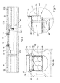
- Figure 7 shows a top view of the embedment box 15 mounted in the embedment hole 13 of the hollow floor structure 10.
- One fixing hole 31 of the mounting brackets 16 is slot-shaped while the other fixing holes 32 are circular and laterally and longitudinally displaced in relation to the slot-shaped fixing hole 31.
- the cover lid of the upper part is removed and shows a levelling thread 71 of the holder device 48, which levelling thread co-operates with the previously described levelling screws.
- the holder device 48 acts in addition on one hand as fitting frame in which outlets are mounted and on the other hand as mounting appliance for the floor box that later, after flooring has been laid-out, is mounted in the embedment box.
- the figure also shows the ground connection 45 on the bottom wall 21 of the box.
- This described method for mounting is a feasible mounting method within the scope of the invention, but it is also possible that the mounting steps 10, 11 and 12 are carried out simultaneously by, before the mounting step 10, adjusting also the levelling to the final level and after that both filling the gap around the embedment box with concrete and filling up to the final floor level.
Landscapes
- Engineering & Computer Science (AREA)
- Architecture (AREA)
- Civil Engineering (AREA)
- Structural Engineering (AREA)
- Connection Or Junction Boxes (AREA)
- Medicines That Contain Protein Lipid Enzymes And Other Medicines (AREA)
- Foundations (AREA)
Abstract
Description
- The present invention relates to the area of the installation of electrically conducting cables in floor structures and particularly in hollow floor structures.
- In the new production of blocks of offices, prefabricated hollow floor structures, so-called HDF floor structures, are often used for providing the different floor plans. The floor structures are delivered in lengths of up to 12 m having 4 to 6 longitudinal tubular hollow spaces, the floor structure is formed in such a way that no additional reinforcement of its strength is needed, which means that, in order to complete the floor, it is desired to apply as little self-levelling screed/concrete as possible, which means a layer from a few centimetres or more.
- Existing embedment systems of connection boxes require a topping of self-levelling screed/concrete from 70 mm to at least 100 mm. The problem of said embedment systems is that the internal space in the floor box mounted in the embedment box for plug connection then becomes limited, which results in the lid of the floor box not being possible to close.
- The object of the present invention is to provide an embedment box of a hollow floor structure, which solves the above-mentioned problems by affording considerably more generous mounting volumes for the electrical installations than what previously has been the case.
- The object is further to provide a mounting device for an embedment box in such a hollow floor structure.
- The object is further to provide such a mounting device that gives the possibility of pre-setting the vertical level of the box in relation to the hollow floor structure.
- By the present invention, as the same is seen in the independent claim, the above-mentioned objects are met, whereby said disadvantages have been eliminated. Suitable embodiments of the invention are defined in the dependent claims.
- The invention is based on using the longitudinal channels in the hollow floor structure for the installation of floor boxes and also for the cabling in the longitudinal channels thereof, without, by this installation and cabling, altering the strength of the hollow floor structure. This is provided by mounting an embedment box in the hollow floor structure. Cabling in another direction than in the longitudinal channels of the floor structure may be carried out in partition walls or in false ceilings of the floor plan below. In addition, cablings may be effected transversely to the hollow space channels of the floor structure by the embedment box having connections for cabling ducts also on the upper side.
- The invention concerns an embedment box of a hollow floor structure, which box comprises a bottom wall, side walls, and end walls as well as at least one top wall, which walls limit the inner volume of the box. At least one of said walls is provided with a breakout opening in which a tube adapter is mounted for the connection of a wiring tube for wiring/cabling. The top wall is provided with an upper part through which the inner volume of the box can be reached. Furthermore, the width of the box is smaller than the width of a channel in the hollow floor structure. The embedment box is further provided with level-fixing means connectable to the hollow floor structure. These members allow an adjustment of the vertical position of the box in relation to the floor structure. The members may be of varying design such as angle-irons that have been attached to the surface of the floor structure or pressing devices that operate between the wall/walls of the embedment box and the channel walls of the inside of the floor structure. They may also be formed to operate between the bottom of the embedment box and the bottom of the inside of the channel of the floor structure. It is also feasible that the members may be formed as wire devices, which by a rotary motion provides a level regulation of the embedment box. All embodiments of the level-fixing means may, however, be adjusted for different vertical positions of the embedment box.
- In one embodiment of the embedment box, for the mounting in said hollow floor structure, the outside of some one of the walls of the embedment box is provided with at least one bracket attachment onto which an adjustable mounting bracket is mounted. The adjustability of the mounting bracket means that a fitter already upon the mounting of the box can adjust the same to an estimated final level of the finished concrete floor surface. This mounting may also be made for different installation alternatives of tubings, which optimizes the installation work considerably.
- In one embodiment of the embedment box, the mounting bracket is rotatably and lockably connected to the bracket attachment. This rotatability further increases the installation alternatives by the fact that different vertical positions can be selected.
- In one embodiment of the embedment box, the mounting bracket is formed as an L-shaped means having a first branch, provided with a position hole for the fastening to said bracket attachment, as well as a second branch, oriented 90° from the first branch and provided with at least one fixing hole for the fastening to the surface of the hollow floor structure. This angled design of the mounting bracket implies a very rigid clamping during an embedment procedure when the embedment box on no account must be dislodged from its position.
- In one embodiment of the embedment box, the position hole of the first branch is formed as a slot having an extension in the direction of the first branch. This slot shape further increases the possibilities of more accurately determining the vertical position of the embedment box at the same time as four discrete positions can be selected by only one fixing screw.
- In one embodiment of the embedment box, the fixing hole of the second branch is formed as a slot having an extension in the direction of the second branch. Also this slot shape makes it easier to select fastening place for a nail/screw/rivet/bolt in the concrete for the mounting bracket.
- In one embodiment of the embedment box, the second branch is further provided with an additional one to four fixing holes, which are placed laterally displaced in the branch in relation to said position hole. Said additional fixing holes allow further fastening options or alternative fastening places for the mounting bracket against the concrete, which further increases the attachment possibilities.
- In one embodiment of the embedment box, the walls of the box are provided with four bracket attachments each one of which provided with a mounted adjustable mounting bracket. By affording several fastening places, greater possibilities of adjustments as well as safer fixation are provided.
- In one embodiment of the embedment box, the four bracket attachments are symmetrically placed in relation to the upper part of the box. A symmetrical placement of the brackets implies a favourable distribution of load upon the mounting of the entire embedment box.
- In one embodiment of the embedment box, the upper part is rectangularly shaped, the bracket attachments being placed adjacent to the respective corners of the upper part. The placement of the brackets at the corners implies that the levelling into the horizontal position is facilitated.
- In one embodiment of the embedment box, the upper part is provided with a levelling device. This device is a complement to the mounting brackets, which facilitates the fine adjustment to the horizontal position of the upper part and fine adjustment does not have to be made via the slots in the mounting bracket.
- The invention also concerns a method for the mounting of an embedment box according to the embodiments presented above in a hollow floor structure. The method concerns the following mounting steps:
- a) a hole is recessed in the hollow floor structure with a width that does not exceed the width of the hollow space width of the floor structure but that slightly exceeds the width of the embedment box,
- b) at least one breakout opening of the embedment box is opened, in which a tube adapter and a wiring tube are mounted,
- c) at least one adjustable mounting bracket is mounted onto the embedment box in a selected position for a coarse adjustment of the height of the embedment box in relation to the level of the surface of the hollow floor structure,
- d) the embedment box is lowered into the recessed hole in the hollow floor structure as well as is adjusted longitudinally in the hole,
- e) the embedment box is fixed in the upper side of the hollow floor structure by means of the mounting bracket,
- f) the longitudinal channel of the hollow floor structure is closed on both sides of the box,
- g) the gap around the embedment box is filled with concrete up to the level of the surface of the hollow floor structure.
- In one embodiment of the method, the mounting step c) is replaced by at least one adjustable mounting bracket being mounted onto the embedment box in a selected position for a coarse adjustment of the height of the embedment box in relation to the level of the finished concrete floor, and the mounting step g) is replaced by concrete being filled into the gap around the embedment box and up to a level corresponding to the finished concrete floor. This modification allows that embedment and topping into the finished concrete floor is made simultaneously in one step on the same occasion, which eliminates the need of two concreting times.
- In one embodiment of the method, some of the mounting steps a) to g) comprises that the level of the upper part of the embedment box is fine-adjusted. This fine adjustment is made either in the slots of the mounting brackets or by a separate levelling device. The fine adjustment provides a more accurate horizontal position of the embedment box and/or its upper part.
- Now, the invention will be described in more detail, reference being made in connection with the accompanying drawing figures. The drawing figures show only explanatory sketches intended to facilitate the understanding of the invention.
- Figure 1
- shows a perspective view of an embedment box according to the present invention mounted in a hollow floor structure.
- Figure 2
- shows only the embedment box in perspective view with the mounting appliances thereof according to the invention.
- Figure 3
- shows a section view along a hollow space in the floor structure having an embedment box mounted.
- Figure 4a
- shows a section view transverse to a hollow space in the floor structure with the section taken also through the embedment box.
- Figure 4b
- shows an enlargement of the encircled part in
Figure 4a . - Figure 5
- shows only the embedment box in perspective view with the mounting appliances thereof according to the invention adjusted for a level position A.
- Figure 6
- shows only the embedment box in perspective view with the mounting appliances thereof according to the invention adjusted for a level position D.
- Figure 7
- shows a top view of an area of the floor structure having a hollow space wherein an embedment box is mounted.
-
Figure 1 shows ahollow floor structure 10 of concrete, which is provided with longitudinal hollow spaces in the form ofchannels 11. Between thechannels 11,webs 12 are formed, which are the principal force-absorbing part of the hollow floor structure and therefore determine the strength of the floor structure. Anembedment hole 13 is recessed in thesurface 14 of thehollow floor structure 10 straight above one of thechannels 11. In the embedment hole, anembedment box 15 is lowered and attached by means of at least oneadjustable mounting bracket 16. The figure shows four identical mounting brackets, which all are mounted onto the embedment box in the same relative position. Furthermore, awiring tube 171 is connected to the end wall of theembedment box 15 for wiring/cabling to the box. Thewiring tube 171 extends through thechannel 11 in thehollow floor structure 10 in which theembedment box 15 is mounted. The figure also shows thatsecond wiring tubes 172 may be connected to theembedment box 15 from the bottom wall thereof and thereby extend out through the bottom of the channel of the hollow floor structure. Alsothird wiring tubes 173 may be connected to theembedment box 15 from the top wall thereof and thereby extend upward and out through theembedment hole 13. Thus, different types of wiring tubes may be connected to different side walls of the embedment box and extend out through the hollow floor structure in several conceivable ways. Theembedment box 15 is furthermore provided with anupper part 18 connected to the top wall of theembedment box 15. -
Figure 2 shows theproper embedment box 15, which is provided with abottom wall 21,side walls 22, and endwalls 23 as well as atop wall 24 on each side of theupper part 18 of the embedment box. Hereby, the walls limit theinner volume 25 of the box, which can be reached via theupper part 18. The figure also shows that the embedment box is provided withbreakout openings 26 placed in theend wall 23 as well as in thetop walls 24. As previously mentioned, also the bottom wall may be provided with such breakout openings. Theembedment box 15 is provided with fourbracket attachments 27 symmetrically placed around theupper part 18. Four adjustable mountingbrackets first branch 28, provided with a slot-shapedposition hole 29 for the fastening to saidbracket attachment 27, as well as asecond branch 30, oriented 90° from the first branch and provided with at least one fixinghole 31 for the fastening to the surface of the hollow floor structure. - Also the fixing
hole 31 of thesecond branch 30 is formed as a slot having an extension in the direction of the second branch. As also is shown in the figure, the second branch is further provided with four additional fixing holes 32, which are placed laterally displaced as well as longitudinally displaced in the branch in relation to said slot-shaped fixing hole. - By the fact that the
position hole 29 of thefirst branch 28 is formed as a slot, the mounting bracket can be displaced to the two end positions of the slot, which define two different mounting levels of the embedment box in relation to the surface of the hollow floor structure. Furthermore, the mounting bracket can be rotated 180° around its bracket attachment, wherein two additional mounting levels defined are usable. In one embodiment, said levels are fixed to A = 0, B = 25 mm, C = 50 mm and D = 75 mm. The figure shows thefirst mounting bracket 161 in the position C and the second 162, the third 163, and thefourth mounting bracket 164 in the position A. Since the position hole is formed as a slot, naturally variable mounting positions are feasible. An alternative to said slots is to provide the first branch with two holes, suitably at a distance from each other of 25 mm in order to achieve the same discrete four positions. Both the slot and possible holes are centrally placed in the branch, oriented longitudinally. As is seen in the figure, the mounting brackets are fixed to the embedment box in their respective positions by means of a fixing screw. -
Figure 3 shows a longitudinal section through anembedment box 15 mounted in ahollow floor structure 10. The mountingbrackets 16 of the embedment box have been mounted in one suitable position of the four discrete positions, i.e., the separated positions,wiring tubes first tube adapter 310 in the breakout opening of an end wall as well as to asecond tube adapter 320 in the breakout opening of a top wall in theembedment box 15. Next, theembedment box 15 is lowered into theembedment hole 13, wherein it is anchored via the mounting brackets in thesurface 14 of the hollow floor structure. Next, thechannel 11 of the hollow floor structure is sealed on both sides of theembedment box 15 by a homogeneous first pourstop 33 and a tube-penetrable second pourstop 34, which pour stops block flowing concrete from running out into the channel when theembedment hole 13 is filled with concrete up to the level of thesurface 14 of the hollow floor structure. In the mounting case shown in the figure,wiring tubes 173 are mounted to the embedment box to run on top of saidsurface 14, either parallel to the channels or at some angle to the same, for instance 90°, and therefore concrete should be filled up to or above the level of the tubes either in the same filling step or upon an extra filling-up step. In order to accomplish an exact adjustment of theupper part 18 of the embedment box in relation to the finished concrete floor, theupper part 18 is variably adjustable by a levellingdevice 35. In the embodiment illustrated, levelling of the upper part can be effected in the interval of 0-25 mm, wherein fine adjustment can be made variably into positions between said four discrete positions of the embedment box. Thus, in the figure, theupper part 18 is levelled to a position wherein a replenishment of concrete can be made above thewiring tube 173 and on a level with the upper part. In order to accomplish a horizontal mounting of the upper part, the same is provided with levelling in all four corners. -
Figure 4a shows a cross-section through ahollow floor structure 10 and anembedment box 15 mounted therein. Theupper part 18 consists of abase part 41 and atop part 42, the figure showing that the top part has been levelled to a level that is situated above thesurface 14 of the floor structure and the mountingbrackets 16 by means of the levelling screws 43, 44. Since theembedment box 15 will contain electrical equipment, the bottom of the box is internally provided with aground connection 45. -
Figure 4b shows a detailed view of the levellingdevice 35. The figure shows thebase part 41 of theupper part 18 and thetop part 42 thereof inside which acover lid 46 is inserted to protect the top part from dirt and the like. The under side of the base part is provided with ascrew holder 47 in which a levellingscrew 44 is secured but can rotate. The levelling screw is provided with threads, which co-operate with the corresponding levelling threads of aholder device 48 in the embedment box. Furthermore, thetop part 42 is provided with a levellinghole 49 through which a screwdriver can reach the head of the levelling screw in order to rotate the screw and in such a way adjust the level of thetop part 42 of theupper part 18. Also the upper side of thecover lid 46 is provided with a hole oriented in line with the levellinghole 49 for allowing levelling to be made without removing the cover lid. -
Figure 5 shows theembedment box 15 withwiring tubes tube adapters breakout openings 26. The mountingbrackets 16 are mounted in their top position A, i.e., for the lowest possible mounting of the embedment box. The levelling of the top part of the upper part is adjusted to its lowest level by the four levelling screws having been rotated to said level by a screwdriver through the fourholes 51 in thecover lid 46. In this connection, the top part is downwardly adjusted and is inside thebase part 41. -
Figure 6 shows theembedment box 15 with the mountingbrackets 16 mounted in their lowermost position D, i.e., for the highest possible mounting of the embedment box. Furthermore, the levelling of thetop part 42 is adjusted to its highest level in relation to thebase part 41 by means of the levelling screws through theholes 51. With the mounting levels and adjustment intervals indicated above, this implies that the level of thetop part 42 and of thecover lid 46 is lying 100 mm above the surface of the hollow floor structure of the embodiment shown when theembedment box 15 is mounted. - By the fact that the levelling screws are four in number and placed in each corner of the upper part, the level of the top part and the cover lid can accordingly be adjusted by means of laser measuring devices to become completely horizontal.
-
Figure 7 shows a top view of theembedment box 15 mounted in theembedment hole 13 of thehollow floor structure 10. One fixinghole 31 of the mountingbrackets 16 is slot-shaped while the other fixingholes 32 are circular and laterally and longitudinally displaced in relation to the slot-shapedfixing hole 31. The cover lid of the upper part is removed and shows a levellingthread 71 of theholder device 48, which levelling thread co-operates with the previously described levelling screws. Theholder device 48 acts in addition on one hand as fitting frame in which outlets are mounted and on the other hand as mounting appliance for the floor box that later, after flooring has been laid-out, is mounted in the embedment box. The figure also shows theground connection 45 on thebottom wall 21 of the box. - A method for the mounting of an embedment box of a hollow floor structure is effected according to the following steps where indicated reference numerals relate to the drawing figures:
- 1. Either before or after the hollow floor structure has been lifted in place, an
embedment hole 13 is recessed in thehollow floor structure 10 with a width that does not exceed the width of the hollow space width of the floor structure, wherein said recessed hole does not affect the strength of the floor structure. In one application of the invention, the width is 170 mm. The hole making may accordingly be made on site or in the factory where the hollow floor structure is produced. - 2. Next, the number of
openings 26 in theembedment box 15 required for the connection of the pipes and tubes appropriate in the application in question are opened. In one embodiment of the embedment box, there are six holes in its bottom, three holes in a short side and four holes in its upper side. - 3. Next,
tube adapters - 4. Next, the mounting
brackets 16 are mounted onto theembedment box 15 for a coarse adjustment of its height to the estimated level of the finished floor. The levels that can be selected depend on how the attachment is placed on the embedment box. In one embodiment, each attachment can be placed in one of the following four positions: A = 0-25 mm; B = 25-50 mm; C = 50-75 mm; D = 75-100 mm. - 5. After the mounting of the mounting brackets, the embedment box is lowered into the recessed
embedment hole 13 in thehollow floor structure 10. - 6. After that, the
wiring tubes longitudinal channels 11 in thehollow floor structure 10. From the channels, the wiring tubes may be led up or down in connecting partition walls to the hollow floor structure. The tubes may also be led on the upper side of the floor structure in those cases the layer thickness of the cast-on layer of self-levelling screed/concrete allows this. - 7. Next, the position of the
embedment box 15 is longitudinally adjusted in theembedment hole 13. - 8. After that, the embedment box is fixed in the upper side of the
hollow floor structure 10 by screwing or by means of a bolt gun in the preferably prepunched holes of the mounting brackets. - 9. After that, the
longitudinal channel 11 in thehollow floor structure 10 is closed by pourstops - 10. Next, the gap around the embedment box is filled with concrete up to the level of the hollow floor structure.
- 11. After that, the height of the upper part of the embedment box is fine-adjusted in the interval of 0-25 mm by means of the levelling screws of the upper part, and by said fine adjustment, the adjustable upper part is levelled in place so that it becomes horizontal and is on a level with the finished concrete floor to be made. The levelling screws of the four corners of the upper part of the embedment box make that the upper part can lie completely horizontally with the finished floor.
- 12. Next, concrete or self-levelling screed is laid out over the floor structure in order to get the finished concrete floor on top of which a carpet or another flooring is laid.
- 13. After the filling has set, the protective lid of the embedment box is lifted away, outlets being mounted in the fitting frame of the embedment box. Next, the outlets are connected and the lid is put back into the hole to prevent anyone from getting hurt if the hole is open.
- 14. Next, the flooring is laid on the finished concrete floor, a floor box being mounted in the hole. The fitting frame is now mounted in the floor box in which the frame and then the respective apparatus, such as high- or low-voltage outlet, are mounted.
- This described method for mounting is a feasible mounting method within the scope of the invention, but it is also possible that the mounting
steps step 10, adjusting also the levelling to the final level and after that both filling the gap around the embedment box with concrete and filling up to the final floor level.
Claims (13)
- Embedment box (15) of a hollow floor structure (10), which box comprises a bottom wall (21), side walls (22), and end walls (23) as well as at least one top wall (24), which walls limit the inner volume (25) of the box, at least one of said walls being provided with a breakout opening (26) in which a tube adapter (310, 320) is mounted for the connection of a wiring tube (171, 172, 173) for wiring/cabling, and that the top wall (24) is provided with an upper part (18) through which the inner volume of the box can be reached, and that the width of the box is smaller than the width of a channel (11) in the hollow floor structure (10), and that the box (15) is provided with level-fixing means connectable to the hollow floor structure (10), characterized in that the outside of some one of the walls of the box is provided with at least one bracket attachment (27) onto which an adjustable mounting bracket (16) as level-fixing means is mounted.
- Embedment box according to claim 1, characterized in that the mounting bracket (16) is rotatably and lockably connected to the bracket attachment (27).
- Embedment box according to any one of claims 1-2, characterized in that the mounting bracket (16) is formed as an L-shaped means having a first branch (28), provided with a position hole (29) for the fastening to said bracket attachment (27), as well as a second branch (30), oriented 90° from the first branch (28) and provided with at least one fixing hole (31) for the fastening to the surface (14) of the hollow floor structure (10).
- Embedment box according to claim 3, characterized in that the position hole (29) of the first branch (28) is formed as a slot having an extension in the direction of the first branch (28).
- Embedment box according to any one of claims 3-4, characterized in that the fixing hole (31) of the second branch (30) is formed as a slot having an extension in the direction of the second branch (30).
- Embedment box according to claim 5, characterized in that the second branch (30) is further provided with an additional one to four fixing holes (32), which are placed laterally displaced in the branch in relation to said fixing hole (31).
- Embedment box according to any one of claims 1-6, characterized in that the walls of the box are provided with four bracket attachments (27) each one of which provided with a mounted adjustable mounting bracket (16).
- Embedment box according to claim 7, characterized in that the four bracket attachments (27) are symmetrically placed in relation to the upper part (18) of the box.
- Embedment box according to claim 8, characterized in that the upper part (18) is rectangularly shaped, the bracket attachments (27) being placed adjacent to the respective corner of the upper part (18).
- Embedment box according to claim 9, characterized in that the upper part (18) is provided with a levelling device (35).
- Method for the mounting of an embedment box (15) formed according to any one of claims 1-10 in a hollow floor structure (10), characterized by the following mounting steps:a) a hole (13) is recessed in the hollow floor structure (10) with a width that does not exceed the width of the hollow space width of the floor structure but that slightly exceeds the width of the embedment box (15),b) at least one breakout opening (26) of the embedment box is opened, in which a tube adapter (310) and a wiring tube (171) are mounted,c) at least one adjustable mounting bracket (16) is mounted onto the embedment box (15) in a selected position for a coarse adjustment of the height of the embedment box in relation to the level of the surface (14) of the hollow floor structure,d) the embedment box is lowered into the recessed hole (13) in the hollow floor structure as well as is adjusted longitudinally in the hole,e) the embedment box (15) is fixed in the upper side of the hollow floor structure (10) by means of the mounting bracket (16),f) the longitudinal channel (11) in the hollow floor structure (15) is closed on both sides of the box,g) the gap around the embedment box (15) is filled with concrete up to the level of the surface (14) of the hollow floor structure.
- Method according to claim 11, characterized in that the mounting step c) instead concerns: at least one adjustable mounting bracket (16) is mounted onto the embedment box (15) in a selected position for a coarse adjustment of the height of the embedment box in relation to the level of the finished concrete floor, and the mounting step g) instead concerns: concrete is filled into the gap around the embedment box (15) and up to a level corresponding to the finished concrete floor.
- Method according to any one of claims 11-12, characterized in that some of the mounting steps a) to g) comprises that the level of the upper part (18) of the embedment box (15) is fine-adjusted.
Applications Claiming Priority (1)
| Application Number | Priority Date | Filing Date | Title |
|---|---|---|---|
| SE1150892A SE536214C2 (en) | 2011-09-28 | 2011-09-28 | Casting box for cavity floor joists and method for mounting one |
Publications (3)
| Publication Number | Publication Date |
|---|---|
| EP2575223A2 true EP2575223A2 (en) | 2013-04-03 |
| EP2575223A3 EP2575223A3 (en) | 2014-03-05 |
| EP2575223B1 EP2575223B1 (en) | 2016-03-30 |
Family
ID=47071121
Family Applications (1)
| Application Number | Title | Priority Date | Filing Date |
|---|---|---|---|
| EP12186421.9A Not-in-force EP2575223B1 (en) | 2011-09-28 | 2012-09-27 | An embedment box for hollow floor structure as well as a method for the mounting of the same |
Country Status (3)
| Country | Link |
|---|---|
| EP (1) | EP2575223B1 (en) |
| DK (1) | DK2575223T3 (en) |
| SE (1) | SE536214C2 (en) |
Cited By (1)
| Publication number | Priority date | Publication date | Assignee | Title |
|---|---|---|---|---|
| CN114447847A (en) * | 2021-12-24 | 2022-05-06 | 常熟市博海新型建材有限公司 | A kind of laminated board junction box and construction method thereof |
Family Cites Families (5)
| Publication number | Priority date | Publication date | Assignee | Title |
|---|---|---|---|---|
| SE463182B (en) * | 1989-02-07 | 1990-10-15 | Thorsman & Co Ab | ELDOSA WITH FIXING DEVICE MUST BE FIXED IN ELECTRICAL CHANNELS |
| GB2257846B (en) * | 1991-06-20 | 1995-01-18 | Mk Electric Ltd | Outlet boxes |
| SE0201808L (en) * | 2002-06-11 | 2003-09-09 | Thorsman & Co Ab | Casting box for electric floor installations |
| US7157643B2 (en) * | 2004-08-05 | 2007-01-02 | Thomas & Betts International, Inc. | Floor box with voltage divider |
| US7476803B2 (en) * | 2007-04-27 | 2009-01-13 | Thomas & Betts International, Inc. | Multi-media recessed data low voltage box with cover |
-
2011
- 2011-09-28 SE SE1150892A patent/SE536214C2/en not_active IP Right Cessation
-
2012
- 2012-09-27 DK DK12186421.9T patent/DK2575223T3/en active
- 2012-09-27 EP EP12186421.9A patent/EP2575223B1/en not_active Not-in-force
Non-Patent Citations (1)
| Title |
|---|
| None |
Cited By (2)
| Publication number | Priority date | Publication date | Assignee | Title |
|---|---|---|---|---|
| CN114447847A (en) * | 2021-12-24 | 2022-05-06 | 常熟市博海新型建材有限公司 | A kind of laminated board junction box and construction method thereof |
| CN114447847B (en) * | 2021-12-24 | 2024-03-26 | 常熟市博海新型建材有限公司 | Superimposed sheet line box and construction method thereof |
Also Published As
| Publication number | Publication date |
|---|---|
| SE536214C2 (en) | 2013-07-02 |
| EP2575223B1 (en) | 2016-03-30 |
| EP2575223A3 (en) | 2014-03-05 |
| SE1150892A1 (en) | 2013-03-29 |
| DK2575223T3 (en) | 2016-07-04 |
Similar Documents
| Publication | Publication Date | Title |
|---|---|---|
| RU2046170C1 (en) | Wall with two panels being apart from one another | |
| US7836659B1 (en) | Method of repairing concrete floors and system for same | |
| EP2575224B1 (en) | A device for an embedment box of a hollow floor structure | |
| US7501576B2 (en) | Ceiling raceway | |
| CN103633584B (en) | The counter of a kind of office network wears cable wiring manufacture technique | |
| US20140000192A1 (en) | Wall assembly for a building structure | |
| DE102018103649A1 (en) | Sanitary wall module and method for building a sanitary wall | |
| EP2575223B1 (en) | An embedment box for hollow floor structure as well as a method for the mounting of the same | |
| EP2260157B1 (en) | Floor assembly as well as panel suitable for such a floor assembly | |
| EP2093341B1 (en) | Wall system | |
| US2741117A (en) | Cellular floor structure for an electrical wire distributing system | |
| RU2342502C1 (en) | Leave-in-place form block | |
| US1956879A (en) | Method of installing underfloor duct systems | |
| DE19963046B4 (en) | Kit for producing at least one supply line system in a building | |
| EP2177689B1 (en) | Frame with cover | |
| ITPD20070392A1 (en) | PERFECT BUILT-IN WARDROBE | |
| RU57324U1 (en) | TRANSMISSION SUPPORT OF LINES OF ELECTRIC TRANSMISSIONS | |
| KR100407038B1 (en) | Full wiring floor system for office building | |
| CH699263B1 (en) | Underfloor trunking system. | |
| RU2772167C2 (en) | Formwork system | |
| KR200236416Y1 (en) | Full wiring floor system for office building | |
| NO322882B1 (en) | Electrical and possibly heating technical subfloor installation for buildings, especially for new buildings for residential formal. | |
| JP3123701B2 (en) | Office structure | |
| HUP0104880A2 (en) | Precast dwelling unit for buildings | |
| NL2010521C2 (en) | CONCRETE WALL PLATE. |
Legal Events
| Date | Code | Title | Description |
|---|---|---|---|
| PUAI | Public reference made under article 153(3) epc to a published international application that has entered the european phase |
Free format text: ORIGINAL CODE: 0009012 |
|
| AK | Designated contracting states |
Kind code of ref document: A2 Designated state(s): AL AT BE BG CH CY CZ DE DK EE ES FI FR GB GR HR HU IE IS IT LI LT LU LV MC MK MT NL NO PL PT RO RS SE SI SK SM TR |
|
| AX | Request for extension of the european patent |
Extension state: BA ME |
|
| PUAL | Search report despatched |
Free format text: ORIGINAL CODE: 0009013 |
|
| AK | Designated contracting states |
Kind code of ref document: A3 Designated state(s): AL AT BE BG CH CY CZ DE DK EE ES FI FR GB GR HR HU IE IS IT LI LT LU LV MC MK MT NL NO PL PT RO RS SE SI SK SM TR |
|
| AX | Request for extension of the european patent |
Extension state: BA ME |
|
| RIC1 | Information provided on ipc code assigned before grant |
Ipc: H02G 3/38 20060101ALI20140130BHEP Ipc: H02G 3/18 20060101AFI20140130BHEP |
|
| 17P | Request for examination filed |
Effective date: 20140905 |
|
| RBV | Designated contracting states (corrected) |
Designated state(s): AL AT BE BG CH CY CZ DE DK EE ES FI FR GB GR HR HU IE IS IT LI LT LU LV MC MK MT NL NO PL PT RO RS SE SI SK SM TR |
|
| GRAP | Despatch of communication of intention to grant a patent |
Free format text: ORIGINAL CODE: EPIDOSNIGR1 |
|
| INTG | Intention to grant announced |
Effective date: 20151013 |
|
| GRAS | Grant fee paid |
Free format text: ORIGINAL CODE: EPIDOSNIGR3 |
|
| GRAA | (expected) grant |
Free format text: ORIGINAL CODE: 0009210 |
|
| RAP1 | Party data changed (applicant data changed or rights of an application transferred) |
Owner name: SCHNEIDER ELECTRIC INDUSTRIES SAS |
|
| AK | Designated contracting states |
Kind code of ref document: B1 Designated state(s): AL AT BE BG CH CY CZ DE DK EE ES FI FR GB GR HR HU IE IS IT LI LT LU LV MC MK MT NL NO PL PT RO RS SE SI SK SM TR |
|
| REG | Reference to a national code |
Ref country code: GB Ref legal event code: FG4D |
|
| REG | Reference to a national code |
Ref country code: CH Ref legal event code: EP |
|
| REG | Reference to a national code |
Ref country code: AT Ref legal event code: REF Ref document number: 786309 Country of ref document: AT Kind code of ref document: T Effective date: 20160415 |
|
| REG | Reference to a national code |
Ref country code: IE Ref legal event code: FG4D |
|
| REG | Reference to a national code |
Ref country code: DE Ref legal event code: R096 Ref document number: 602012016214 Country of ref document: DE |
|
| REG | Reference to a national code |
Ref country code: SE Ref legal event code: TRGR |
|
| REG | Reference to a national code |
Ref country code: DK Ref legal event code: T3 Effective date: 20160627 |
|
| REG | Reference to a national code |
Ref country code: NO Ref legal event code: T2 Effective date: 20160330 Ref country code: LT Ref legal event code: MG4D |
|
| PG25 | Lapsed in a contracting state [announced via postgrant information from national office to epo] |
Ref country code: GR Free format text: LAPSE BECAUSE OF FAILURE TO SUBMIT A TRANSLATION OF THE DESCRIPTION OR TO PAY THE FEE WITHIN THE PRESCRIBED TIME-LIMIT Effective date: 20160701 Ref country code: HR Free format text: LAPSE BECAUSE OF FAILURE TO SUBMIT A TRANSLATION OF THE DESCRIPTION OR TO PAY THE FEE WITHIN THE PRESCRIBED TIME-LIMIT Effective date: 20160330 |
|
| REG | Reference to a national code |
Ref country code: NL Ref legal event code: MP Effective date: 20160330 |
|
| REG | Reference to a national code |
Ref country code: AT Ref legal event code: MK05 Ref document number: 786309 Country of ref document: AT Kind code of ref document: T Effective date: 20160330 |
|
| PG25 | Lapsed in a contracting state [announced via postgrant information from national office to epo] |
Ref country code: LT Free format text: LAPSE BECAUSE OF FAILURE TO SUBMIT A TRANSLATION OF THE DESCRIPTION OR TO PAY THE FEE WITHIN THE PRESCRIBED TIME-LIMIT Effective date: 20160330 Ref country code: RS Free format text: LAPSE BECAUSE OF FAILURE TO SUBMIT A TRANSLATION OF THE DESCRIPTION OR TO PAY THE FEE WITHIN THE PRESCRIBED TIME-LIMIT Effective date: 20160330 Ref country code: LV Free format text: LAPSE BECAUSE OF FAILURE TO SUBMIT A TRANSLATION OF THE DESCRIPTION OR TO PAY THE FEE WITHIN THE PRESCRIBED TIME-LIMIT Effective date: 20160330 |
|
| REG | Reference to a national code |
Ref country code: FR Ref legal event code: PLFP Year of fee payment: 5 |
|
| PG25 | Lapsed in a contracting state [announced via postgrant information from national office to epo] |
Ref country code: NL Free format text: LAPSE BECAUSE OF FAILURE TO SUBMIT A TRANSLATION OF THE DESCRIPTION OR TO PAY THE FEE WITHIN THE PRESCRIBED TIME-LIMIT Effective date: 20160330 |
|
| PG25 | Lapsed in a contracting state [announced via postgrant information from national office to epo] |
Ref country code: IS Free format text: LAPSE BECAUSE OF FAILURE TO SUBMIT A TRANSLATION OF THE DESCRIPTION OR TO PAY THE FEE WITHIN THE PRESCRIBED TIME-LIMIT Effective date: 20160730 Ref country code: PL Free format text: LAPSE BECAUSE OF FAILURE TO SUBMIT A TRANSLATION OF THE DESCRIPTION OR TO PAY THE FEE WITHIN THE PRESCRIBED TIME-LIMIT Effective date: 20160330 Ref country code: EE Free format text: LAPSE BECAUSE OF FAILURE TO SUBMIT A TRANSLATION OF THE DESCRIPTION OR TO PAY THE FEE WITHIN THE PRESCRIBED TIME-LIMIT Effective date: 20160330 |
|
| PG25 | Lapsed in a contracting state [announced via postgrant information from national office to epo] |
Ref country code: PT Free format text: LAPSE BECAUSE OF FAILURE TO SUBMIT A TRANSLATION OF THE DESCRIPTION OR TO PAY THE FEE WITHIN THE PRESCRIBED TIME-LIMIT Effective date: 20160801 Ref country code: CZ Free format text: LAPSE BECAUSE OF FAILURE TO SUBMIT A TRANSLATION OF THE DESCRIPTION OR TO PAY THE FEE WITHIN THE PRESCRIBED TIME-LIMIT Effective date: 20160330 Ref country code: AT Free format text: LAPSE BECAUSE OF FAILURE TO SUBMIT A TRANSLATION OF THE DESCRIPTION OR TO PAY THE FEE WITHIN THE PRESCRIBED TIME-LIMIT Effective date: 20160330 Ref country code: RO Free format text: LAPSE BECAUSE OF FAILURE TO SUBMIT A TRANSLATION OF THE DESCRIPTION OR TO PAY THE FEE WITHIN THE PRESCRIBED TIME-LIMIT Effective date: 20160330 Ref country code: ES Free format text: LAPSE BECAUSE OF FAILURE TO SUBMIT A TRANSLATION OF THE DESCRIPTION OR TO PAY THE FEE WITHIN THE PRESCRIBED TIME-LIMIT Effective date: 20160330 Ref country code: SK Free format text: LAPSE BECAUSE OF FAILURE TO SUBMIT A TRANSLATION OF THE DESCRIPTION OR TO PAY THE FEE WITHIN THE PRESCRIBED TIME-LIMIT Effective date: 20160330 Ref country code: SM Free format text: LAPSE BECAUSE OF FAILURE TO SUBMIT A TRANSLATION OF THE DESCRIPTION OR TO PAY THE FEE WITHIN THE PRESCRIBED TIME-LIMIT Effective date: 20160330 |
|
| PG25 | Lapsed in a contracting state [announced via postgrant information from national office to epo] |
Ref country code: BE Free format text: LAPSE BECAUSE OF FAILURE TO SUBMIT A TRANSLATION OF THE DESCRIPTION OR TO PAY THE FEE WITHIN THE PRESCRIBED TIME-LIMIT Effective date: 20160330 Ref country code: IT Free format text: LAPSE BECAUSE OF FAILURE TO SUBMIT A TRANSLATION OF THE DESCRIPTION OR TO PAY THE FEE WITHIN THE PRESCRIBED TIME-LIMIT Effective date: 20160330 |
|
| REG | Reference to a national code |
Ref country code: DE Ref legal event code: R097 Ref document number: 602012016214 Country of ref document: DE |
|
| PLBE | No opposition filed within time limit |
Free format text: ORIGINAL CODE: 0009261 |
|
| STAA | Information on the status of an ep patent application or granted ep patent |
Free format text: STATUS: NO OPPOSITION FILED WITHIN TIME LIMIT |
|
| 26N | No opposition filed |
Effective date: 20170103 |
|
| PG25 | Lapsed in a contracting state [announced via postgrant information from national office to epo] |
Ref country code: MC Free format text: LAPSE BECAUSE OF FAILURE TO SUBMIT A TRANSLATION OF THE DESCRIPTION OR TO PAY THE FEE WITHIN THE PRESCRIBED TIME-LIMIT Effective date: 20160330 |
|
| REG | Reference to a national code |
Ref country code: CH Ref legal event code: PL |
|
| GBPC | Gb: european patent ceased through non-payment of renewal fee |
Effective date: 20160927 |
|
| PG25 | Lapsed in a contracting state [announced via postgrant information from national office to epo] |
Ref country code: SI Free format text: LAPSE BECAUSE OF FAILURE TO SUBMIT A TRANSLATION OF THE DESCRIPTION OR TO PAY THE FEE WITHIN THE PRESCRIBED TIME-LIMIT Effective date: 20160330 |
|
| REG | Reference to a national code |
Ref country code: IE Ref legal event code: MM4A |
|
| PG25 | Lapsed in a contracting state [announced via postgrant information from national office to epo] |
Ref country code: LI Free format text: LAPSE BECAUSE OF NON-PAYMENT OF DUE FEES Effective date: 20160930 Ref country code: GB Free format text: LAPSE BECAUSE OF NON-PAYMENT OF DUE FEES Effective date: 20160927 Ref country code: IE Free format text: LAPSE BECAUSE OF NON-PAYMENT OF DUE FEES Effective date: 20160927 Ref country code: CH Free format text: LAPSE BECAUSE OF NON-PAYMENT OF DUE FEES Effective date: 20160930 |
|
| PG25 | Lapsed in a contracting state [announced via postgrant information from national office to epo] |
Ref country code: LU Free format text: LAPSE BECAUSE OF NON-PAYMENT OF DUE FEES Effective date: 20160927 |
|
| REG | Reference to a national code |
Ref country code: FR Ref legal event code: PLFP Year of fee payment: 6 |
|
| PG25 | Lapsed in a contracting state [announced via postgrant information from national office to epo] |
Ref country code: CY Free format text: LAPSE BECAUSE OF FAILURE TO SUBMIT A TRANSLATION OF THE DESCRIPTION OR TO PAY THE FEE WITHIN THE PRESCRIBED TIME-LIMIT Effective date: 20160330 Ref country code: HU Free format text: LAPSE BECAUSE OF FAILURE TO SUBMIT A TRANSLATION OF THE DESCRIPTION OR TO PAY THE FEE WITHIN THE PRESCRIBED TIME-LIMIT; INVALID AB INITIO Effective date: 20120927 |
|
| PG25 | Lapsed in a contracting state [announced via postgrant information from national office to epo] |
Ref country code: MT Free format text: LAPSE BECAUSE OF NON-PAYMENT OF DUE FEES Effective date: 20160930 Ref country code: MK Free format text: LAPSE BECAUSE OF FAILURE TO SUBMIT A TRANSLATION OF THE DESCRIPTION OR TO PAY THE FEE WITHIN THE PRESCRIBED TIME-LIMIT Effective date: 20160330 Ref country code: TR Free format text: LAPSE BECAUSE OF FAILURE TO SUBMIT A TRANSLATION OF THE DESCRIPTION OR TO PAY THE FEE WITHIN THE PRESCRIBED TIME-LIMIT Effective date: 20160330 |
|
| PG25 | Lapsed in a contracting state [announced via postgrant information from national office to epo] |
Ref country code: BG Free format text: LAPSE BECAUSE OF FAILURE TO SUBMIT A TRANSLATION OF THE DESCRIPTION OR TO PAY THE FEE WITHIN THE PRESCRIBED TIME-LIMIT Effective date: 20160330 |
|
| REG | Reference to a national code |
Ref country code: FR Ref legal event code: PLFP Year of fee payment: 7 |
|
| PG25 | Lapsed in a contracting state [announced via postgrant information from national office to epo] |
Ref country code: AL Free format text: LAPSE BECAUSE OF FAILURE TO SUBMIT A TRANSLATION OF THE DESCRIPTION OR TO PAY THE FEE WITHIN THE PRESCRIBED TIME-LIMIT Effective date: 20160330 |
|
| PGFP | Annual fee paid to national office [announced via postgrant information from national office to epo] |
Ref country code: SE Payment date: 20220916 Year of fee payment: 11 Ref country code: NO Payment date: 20220923 Year of fee payment: 11 Ref country code: FI Payment date: 20220916 Year of fee payment: 11 Ref country code: DK Payment date: 20220915 Year of fee payment: 11 Ref country code: DE Payment date: 20220921 Year of fee payment: 11 |
|
| PGFP | Annual fee paid to national office [announced via postgrant information from national office to epo] |
Ref country code: FR Payment date: 20220915 Year of fee payment: 11 |
|
| REG | Reference to a national code |
Ref country code: DE Ref legal event code: R119 Ref document number: 602012016214 Country of ref document: DE |
|
| REG | Reference to a national code |
Ref country code: DK Ref legal event code: EBP Effective date: 20230930 |
|
| PG25 | Lapsed in a contracting state [announced via postgrant information from national office to epo] |
Ref country code: FI Free format text: LAPSE BECAUSE OF NON-PAYMENT OF DUE FEES Effective date: 20230927 |
|
| REG | Reference to a national code |
Ref country code: SE Ref legal event code: EUG |
|
| PG25 | Lapsed in a contracting state [announced via postgrant information from national office to epo] |
Ref country code: NO Free format text: LAPSE BECAUSE OF NON-PAYMENT OF DUE FEES Effective date: 20230930 Ref country code: FR Free format text: LAPSE BECAUSE OF NON-PAYMENT OF DUE FEES Effective date: 20230930 Ref country code: DE Free format text: LAPSE BECAUSE OF NON-PAYMENT OF DUE FEES Effective date: 20240403 |
|
| PG25 | Lapsed in a contracting state [announced via postgrant information from national office to epo] |
Ref country code: SE Free format text: LAPSE BECAUSE OF NON-PAYMENT OF DUE FEES Effective date: 20230928 |
|
| PG25 | Lapsed in a contracting state [announced via postgrant information from national office to epo] |
Ref country code: DK Free format text: LAPSE BECAUSE OF NON-PAYMENT OF DUE FEES Effective date: 20230930 |
|
| PG25 | Lapsed in a contracting state [announced via postgrant information from national office to epo] |
Ref country code: DK Free format text: LAPSE BECAUSE OF NON-PAYMENT OF DUE FEES Effective date: 20230930 |