EP2575153A2 - Switch pole unit - Google Patents
Switch pole unit Download PDFInfo
- Publication number
- EP2575153A2 EP2575153A2 EP12184683A EP12184683A EP2575153A2 EP 2575153 A2 EP2575153 A2 EP 2575153A2 EP 12184683 A EP12184683 A EP 12184683A EP 12184683 A EP12184683 A EP 12184683A EP 2575153 A2 EP2575153 A2 EP 2575153A2
- Authority
- EP
- European Patent Office
- Prior art keywords
- pole unit
- switch pole
- movable contact
- unit according
- contact
- Prior art date
- Legal status (The legal status is an assumption and is not a legal conclusion. Google has not performed a legal analysis and makes no representation as to the accuracy of the status listed.)
- Granted
Links
Images


Classifications
-
- H—ELECTRICITY
- H01—ELECTRIC ELEMENTS
- H01H—ELECTRIC SWITCHES; RELAYS; SELECTORS; EMERGENCY PROTECTIVE DEVICES
- H01H33/00—High-tension or heavy-current switches with arc-extinguishing or arc-preventing means
- H01H33/60—Switches wherein the means for extinguishing or preventing the arc do not include separate means for obtaining or increasing flow of arc-extinguishing fluid
- H01H33/66—Vacuum switches
- H01H33/666—Operating arrangements
-
- H—ELECTRICITY
- H01—ELECTRIC ELEMENTS
- H01H—ELECTRIC SWITCHES; RELAYS; SELECTORS; EMERGENCY PROTECTIVE DEVICES
- H01H3/00—Mechanisms for operating contacts
- H01H3/32—Driving mechanisms, i.e. for transmitting driving force to the contacts
- H01H3/42—Driving mechanisms, i.e. for transmitting driving force to the contacts using cam or eccentric
-
- H—ELECTRICITY
- H01—ELECTRIC ELEMENTS
- H01H—ELECTRIC SWITCHES; RELAYS; SELECTORS; EMERGENCY PROTECTIVE DEVICES
- H01H33/00—High-tension or heavy-current switches with arc-extinguishing or arc-preventing means
- H01H33/60—Switches wherein the means for extinguishing or preventing the arc do not include separate means for obtaining or increasing flow of arc-extinguishing fluid
- H01H33/66—Vacuum switches
- H01H33/666—Operating arrangements
- H01H2033/6667—Details concerning lever type driving rod arrangements
-
- H—ELECTRICITY
- H01—ELECTRIC ELEMENTS
- H01H—ELECTRIC SWITCHES; RELAYS; SELECTORS; EMERGENCY PROTECTIVE DEVICES
- H01H3/00—Mechanisms for operating contacts
- H01H3/32—Driving mechanisms, i.e. for transmitting driving force to the contacts
- H01H3/48—Driving mechanisms, i.e. for transmitting driving force to the contacts using lost-motion device
Definitions
- the invention relates to a Wegerpolhow, in particular for a vacuum circuit breaker, with a vacuum interrupter chamber (2.1) with at least one fixed contact and at least one movable contact (2.2), in particular a bolt which can be brought via a drive in an on position.
- Vacuum circuit breakers are electrical switches that are designed for high currents and separate an electrical connection in the appropriate vacuum interrupters.
- a conventional vacuum switching chamber has a vacuum housing in which two contacts are arranged. One of the contacts is designed as a fixed contact and the other as a movable contact, usually in the form of a conductor pin.
- In the closed switch state contact the two contacts and thus make an electrical connection. In this state, they are subjected to a continuous contact pressure, which presses the two contacts against each other with a defined force.
- the moving contact is moved away from the fixed contact at high speed and an isolating distance is established between the two contacts.
- the design requirements for the circuit breakers increase. Because the higher the voltage to be switched, the higher the required separation distance, the on and off speeds and the height of the contact pressure.
- Another typical switch pole unit is from the DE 40 06 452 A1 known.
- the driving forces are transmitted here by a switching rod on a control disk.
- the control disk is rotatably mounted and has an arcuately curved LanglochausEnglishung.
- the movable contact has a plunger, which engages in the oblong hole and thereby positively guided.
- the movable contact which is linearly movable in the vacuum interrupter in the switch pole housing, placed in the "on" position and a Ausschaltfeder biased.
- the friction losses are comparatively high, which leads to high wear of the mechanical components and to slow switching times.
- a comparatively large angle of rotation of the control disk for the linear movement of the movable contact required for switching is necessary in the case of the positive guidance provided by the arcuate oblong slot recess, which likewise leads to increased switching times.
- the present invention is therefore an object of the invention to provide a Heidelbergerpoltician whose structure meets the requirements of high voltage ranges and at the same time is simple.
- a linear guide is here understood to mean a machine element from linear technology which permits frictionless translation of the movable contact or an associated drive element which moves linearly in the same direction and at the same time guarantees compliance with the direction of movement - a linear path.
- the linear guide is preferably designed as a recirculating ball bearing guide.
- a recirculating ball bearing is characterized by low static and dynamic rolling friction, low wear and good guidance accuracy over the entire service life. moreover
- the guide can absorb forces in two directions, making it a suitable linear guide for the application.
- the achieved high guidance accuracy and the low friction values are achieved high speeds and a reduction in the mechanical load of the means that provide the movement of the contact.
- a slide-mounted linear guide is also usable.
- the switch pole unit according to the invention has a switch-off spring, which acts directly on the movable contact or an abutment rigidly fastened thereto.
- the movable contact is in direct connection with the opening spring, which leads to rapid accelerations and off times.
- a further preferred embodiment is characterized by a contact pressure acting on the movable contact, in particular when it is arranged axially aligned with the movable contact and acts in the axial direction on the movable contact.
- the pivot point of the connecting rod is to be arranged below the contact pressure device on the longitudinal axis of the movement contact.
- the position of the connecting rod should have the smallest possible angle of inclination to the movement contact in the switched-on switch state in order to obtain a good balance of power against the high contact pressure forces occurring at the end of the switching process.
- connection between the connecting rod and a member on the side of the movable contact is preferably designed with a plain bearing or a still frictional rolling or ball bearing in order to further minimize friction losses.
- the design according to the invention fulfills the requirements of high voltage ranges when using the standard drive. Consequently, can be dispensed with a significant change or the redesign of a drive, creating a significant cost advantage.
- switch pole contents suitable for voltages of up to 40.5 kV or even higher can be designed.
- the in the FIGS. 1 and 2 illustrated switch pole unit 1 has a vacuum switching chamber 2.1, which is arranged in a housing 3.
- a vacuum switching chamber 2.1 which is arranged in a housing 3.
- a first nut 4 which forms a lower contact surface for a Ausschaltfeder 5.
- the upper contact surface for the opening spring 5 forms the housing 3, so that the movable contact 2.2 with the opening spring 5 are in direct operative connection with each other.
- a flexible copper band 6 is connected to the movable contact 2.2, which is held on a cooperating with the nut 4 lower lock nut 7 on the movable contact 2.2.
- the copper band 6 and the movable contact 2.2 are electrically connected to each other and form the lower terminal point of the switch pole unit 1.
- the upper, with the fixed contact in the vacuum interrupter chamber connected terminal point of the switch pole unit is not
- the contact pressure device has a threaded adapter 8, which is firmly connected to the movable contact 2.2.
- the threaded adapter 8 is provided with an upper contact surface for a contact pressure spring 9, which is also part of the contact pressure device and is supported on its lower side on a piston-like drive element 10.
- a guide pin 11 At the bottom of the threaded adapter 8, it has a guide pin 11, whose longitudinal axis is aligned with that of the movable contact 2.2.
- the guide pin 11 is axially guided in a provided in the piston-like drive element 10 bushing 12 and freely movable in the axial direction. Since the drive element forms the lower bearing for the contact pressure spring 9, it is also considered as part of the contact pressure device.
- the piston-like drive element 10 is guided by a linear guide 12 in the axial direction of the movable contact.
- the linear guide is preferably designed as a recirculating ball guide.
- the piston-like drive element is connected via a connecting rod 13 with the crank arm 14 of a crankshaft 15.
- the connecting rod is connected to the piston-like drive element 10 and the crank arm 14 via sliding or roller bearings.
- the crankshaft 15 is made of a non-conductive material.
- FIG. 2 shows the switch pole unit 1 in the on state.
- a connecting rod with the piston cheek 14 connecting crank pin 16 has almost reached its highest point in this state, so that of the Ausschaltfeder 5 while a moment acts on the crankshaft 16, but the moment is as low as possible.
- the drive should be locked by a suitable mechanism.
- the shutdown is carried out by releasing this Ausschaltverrastung (or a sustained drive torque), whereby the entire unit due to the biased Ausschaltfeder 5 back to the initial state, the in FIG. 1 is shown is offset.
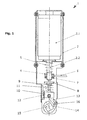
- FIG. 3 shows a further embodiment, in which inertia and friction points are further reduced.
- the Ausschaltverrastung 20 which is usually located in the drive outside the Heidelbergerpoltician, directly integrated in the Heidelbergerpolech 1.
- the Ausschaltverrastung 20 is realized by a mounted in the housing 3 half-wave. After reaching the on position puts the crank arm 21 with a cam-like part 22 behind the half-wave, which faces the crank arm, and the on state is thus maintained.
- the half-wave Ausschaltverrastung 20 is released and the mechanism is returned to the initial state due to the force of the opening spring.
- the drive is designed so that the crankshaft 23 takes the connecting rod 13 only to behind the Ausschaltverrastung 20 and automatically returns from this position back to the starting point.
- the crankshaft 23 is rotatably mounted in the crank arm 21, wherein on the inner bearing surface of the crank arm 21, a franking 24 is provided, in which a crankshaft 23 provided on the shaft pin 25 engages, so that the free path for rotation of the crankshaft 23rd is limited relative to the crank arm 21.
Landscapes
- Driving Mechanisms And Operating Circuits Of Arc-Extinguishing High-Tension Switches (AREA)
- High-Tension Arc-Extinguishing Switches Without Spraying Means (AREA)
Abstract
Die Erfindung betrifft eine Schalterpoleinheit, insbesondere für einen Vakuum-Leistungsschalter, mit einer Vakuumschaltkammer (2.1) mit mindestens einem festen Kontakt und mindestens einem beweglichen Kontakt (2.2), insbesondere einem Bolzen, der über einen Antrieb in eine Einschaltposition gebracht werden kann. Um eine Schalterpoleinheit zu schaffen, deren Aufbau den Anforderungen hoher Spannungsbereiche gerecht wird und gleichzeitig einfach ist, weist die Schalterpoleinheit eine in einem Abstand zur Vakuumschaltkammer (2.1) angeordnete Linearführung (12) zur linearen Führung des beweglichen Kontaktes (2.2) oder eines damit verbundenen, in gleicher Richtung linear bewegten Antriebselements (10) auf.The invention relates to a Schalterpoleinheit, in particular for a vacuum circuit breaker, with a vacuum interrupter chamber (2.1) with at least one fixed contact and at least one movable contact (2.2), in particular a bolt which can be brought via a drive in an on position. In order to provide a switch pole unit whose structure meets the requirements of high voltage ranges and at the same time is simple, the switch pole unit has a spaced from the vacuum interrupter chamber (2.1) arranged linear guide (12) for linear guidance of the movable contact (2.2) or an associated in the same direction linearly moving drive element (10).
Description
Die Erfindung betrifft eine Schalterpoleinheit, insbesondere für einen Vakuum-Leistungsschalter, mit einer Vakuumschaltkammer (2.1) mit mindestens einem festen Kontakt und mindestens einem beweglichen Kontakt (2.2), insbesondere einem Bolzen, der über einen Antrieb in eine Einschaltposition gebracht werden kann.The invention relates to a Schalterpoleinheit, in particular for a vacuum circuit breaker, with a vacuum interrupter chamber (2.1) with at least one fixed contact and at least one movable contact (2.2), in particular a bolt which can be brought via a drive in an on position.
Vakuum-Leistungsschalter sind elektrische Schalter, die für hohe Ströme ausgelegt sind und eine elektrische Verbindung in den dafür vorgesehenen Vakuumschaltkammern trennen. Eine übliche Vakuumschaltkammer weist ein Vakuumgehäuse auf, in dem zwei Kontakte angeordnet sind. Einer der Kontakte ist als Festkontakt und der andere als beweglicher Kontakt, meist in Form eines Leiterbolzens, ausgebildet. Im geschlossenen Schalterzustand kontaktieren sich die beiden Kontakte und stellen somit eine elektrische Verbindung her. In diesem Zustand sind sie mit einem kontinuierlichen Kontaktdruck beaufschlagt, der die beiden Kontakte mit einer definierten Kraft gegeneinander drückt. Zum Trennen der elektrischen Verbindung wird der Bewegungskontakt mit hoher Geschwindigkeit von dem Festkontakt weg bewegt und eine Trennstrecke zwischen den beiden Kontakten hergestellt. Da der Spannungsbereich, in dem derartige Leistungsschalter eingesetzt werden sollen, immer weiter steigt, nehmen die konstruktiven Anforderungen an die Leistungsschalter zu. Denn je höher die zu schaltende Spannung ist, desto höher ist die geforderte Trennstrecke, die Ein- und Ausschaltgeschwindigkeiten sowie die Höhe des Kontaktdruckes.Vacuum circuit breakers are electrical switches that are designed for high currents and separate an electrical connection in the appropriate vacuum interrupters. A conventional vacuum switching chamber has a vacuum housing in which two contacts are arranged. One of the contacts is designed as a fixed contact and the other as a movable contact, usually in the form of a conductor pin. In the closed switch state contact the two contacts and thus make an electrical connection. In this state, they are subjected to a continuous contact pressure, which presses the two contacts against each other with a defined force. To disconnect the electrical connection, the moving contact is moved away from the fixed contact at high speed and an isolating distance is established between the two contacts. As the voltage range in which such circuit breakers are to be used continues to increase, the design requirements for the circuit breakers increase. Because the higher the voltage to be switched, the higher the required separation distance, the on and off speeds and the height of the contact pressure.
In der
Eine weitere typische Schalterpoleinheit ist aus der
Der vorliegenden Erfindung liegt daher die Aufgabe zugrunde, eine Schalterpoleinheit zu schaffen, deren Aufbau den Anforderungen hoher Spannungsbereiche gerecht wird und gleichzeitig einfach ist.The present invention is therefore an object of the invention to provide a Schalterpoleinheit whose structure meets the requirements of high voltage ranges and at the same time is simple.
Erfindungsgemäß wird diese Aufgabe durch die Merkmale des Anspruches 1 gelöst. Bevorzugte Ausgestaltungen der Erfindung ergeben sich aus den Unteransprüchen.According to the invention, this object is solved by the features of claim 1. Preferred embodiments of the invention will become apparent from the dependent claims.
Unter einer Linearführung wird hier ein Maschinenelement aus der Lineartechnik verstanden, das eine möglichst reibungsfreie Translation des beweglichen Kontaktes oder eines damit verbundenen, in gleicher Richtung linear bewegten Antriebselements ermöglicht und dabei gleichzeitig die Einhaltung der Bewegungsrichtung - einer linearen Bahn - garantiert.A linear guide is here understood to mean a machine element from linear technology which permits frictionless translation of the movable contact or an associated drive element which moves linearly in the same direction and at the same time guarantees compliance with the direction of movement - a linear path.
Mit der Verwendung einer in einem Abstand zur Vakuumschaltkammer angeordneten Linearführung wird gegenüber den eingangs beschriebenen, vorbekannten Schalterpoleinheiten zweierlei erreicht. Zum einen ist der bewegliche Kontakt bzw. ein damit verbundenes, in gleicher Richtung linear bewegtes Antriebselement zwangsgeführt, so dass Antriebskräfte, die nicht genau axial übertragen werden, nicht zu einer Querauslenkung des beweglichen Kontaktes oder des damit verbundenen Antriebselementes führen. Hierdurch wird ein planparalleles Anlegen der Kontakte in der Vakuumkammer im Einschaltzustand sichergestellt, was insbesondere bei einer Schalterpoleinheit gemäß der
Die Linearführung ist vorzugsweise als Kugelumlaufführung ausgestaltet. Eine Kugelumlaufführung zeichnet sich durch geringe statische und dynamische Rollreibung, geringen Verschleiß und eine gute Führungsgenauigkeit über die gesamte Lebensdauer aus. Zudem kann die Führung Kräfte in zwei Richtungen aufnehmen, was sie zu einer geeigneten Linearführung für den Anwendungsfall werden lässt. Durch die erzielte hohe Führungsgenauigkeit und die niedrigen Reibwerte werden hohe Geschwindigkeiten und eine Reduzierung der mechanischen Belastung der Mittel, die für die Bewegung des Kontaktes sorgen, erreicht. Naturgemäß ist aber auch eine gleitgelagerte Linearführung verwendbar.The linear guide is preferably designed as a recirculating ball bearing guide. A recirculating ball bearing is characterized by low static and dynamic rolling friction, low wear and good guidance accuracy over the entire service life. moreover For example, the guide can absorb forces in two directions, making it a suitable linear guide for the application. The achieved high guidance accuracy and the low friction values are achieved high speeds and a reduction in the mechanical load of the means that provide the movement of the contact. Naturally, however, a slide-mounted linear guide is also usable.
In einer bevorzugten Ausführungsform weist die erfindungsgemäße Schalterpoleinheit eine Ausschaltfeder auf, die unmittelbar auf den beweglichen Kontakt oder ein daran starr befestigtes Gegenlager wirkt. Somit steht der bewegliche Kontakt in direkter Verbindung mit der Ausschaltfeder, was zu schnellen Beschleunigungen und Ausschaltzeiten führt.In a preferred embodiment, the switch pole unit according to the invention has a switch-off spring, which acts directly on the movable contact or an abutment rigidly fastened thereto. Thus, the movable contact is in direct connection with the opening spring, which leads to rapid accelerations and off times.
Eine weitere bevorzugte Ausführungsform ist gekennzeichnet durch eine auf den beweglichen Kontakt wirkende Kontaktdruckeinrichtung, insbesondere dann, wenn sie axial fluchtend zum beweglichen Kontakt angeordnet ist und in axialer Richtung auf den beweglichen Kontakt wirkt.A further preferred embodiment is characterized by a contact pressure acting on the movable contact, in particular when it is arranged axially aligned with the movable contact and acts in the axial direction on the movable contact.
Die Verwendung einer Linearführung ermöglicht die Verwendung eines Kurbelwellenantriebs mit einem Pleuel, mit der ein vom Antrieb übertragenes Drehmoment in eine auf den Bewegungskontakt axial wirkende Kraft umgesetzt wird, ohne dass die Bewegung des Pleuels quer zur Längsachse des beweglichen Kontaktes eine ungenaue Kontaktierung der Kontakte in der Vakuumschaltkammer zur Folge hat. Gleichzeitig ist eine derartige Übertragung von Antriebskräften konstruktiv sehr einfach und reibungsverlustarm.The use of a linear guide allows the use of a crankshaft drive with a connecting rod, with a torque transmitted from the drive is converted into a force acting on the moving contact force without the movement of the connecting rod transverse to the longitudinal axis of the movable contact inaccurate contacting of the contacts in the Vacuum switching chamber has the consequence. At the same time, such a transmission of drive forces is structurally very simple and low in friction.
Vorteilhafterweise ist der Drehpunkt des Pleuels unterhalb der Kontaktdruckeinrichtung auf der Längsachse des Bewegungskontaktes anzuordnen. Die Lage des Pleuels sollte im eingeschalteten Schalterzustand einen möglichst geringen Neigungswinkel zum Bewegungskontakt haben, um ein gutes Kräfteverhältnis gegen die am Ende des Schaltvorganges auftretenden hohen Kontaktdruckkräfte zu erhalten.Advantageously, the pivot point of the connecting rod is to be arranged below the contact pressure device on the longitudinal axis of the movement contact. The position of the connecting rod should have the smallest possible angle of inclination to the movement contact in the switched-on switch state in order to obtain a good balance of power against the high contact pressure forces occurring at the end of the switching process.
Die Verbindung zwischen dem Pleuel und einem Element auf der Seite des beweglichen Kontaktes ist vorzugsweise mit einem Gleitlager oder einer noch reibungsärmeren Wälz- bzw. Kugellagerung ausgestaltet, um Reibungsverluste weiter zu minimieren.The connection between the connecting rod and a member on the side of the movable contact is preferably designed with a plain bearing or a still frictional rolling or ball bearing in order to further minimize friction losses.
Antriebe für erfindungsgemäße Schalterpoleinheiten, wie auch in der
Demgegenüber besteht eine weitere vorteilhafte Ausgestaltung der Erfindung darin, die Ausschaltverrastung in die Schalterpoleinheit zu integrieren, indem sie insbesondere so ausgebildet ist, dass sie auf eine den Pleuel mit der Kurbelwelle verbindende Kurbel oder Kurbelwange wirken kann. Hierdurch werden die Anzahl der beim Ausschalten zu bewegenden Teile und damit die zu überwindende Massenträgheit ebenso wie Reibungsverluste deutlich reduziert. Im Ergebnis kann dadurch nicht nur die Ausschaltzeit verkürzt werden, sondern auch die für das Ausschalten notwendige Ausschaltfederkraft, wodurch es möglich wird, die Ausschaltfeder kleiner zu dimensionieren.In contrast, there is a further advantageous embodiment of the invention is to integrate the Ausschaltverrastung in the Schalterpoleinheit, in particular by being designed so that it can act on a connecting rod to the crankshaft crank or crank arm. As a result, the number of parts to be moved when switching off and thus the mass inertia to be overcome as well as friction losses are significantly reduced. As a result, not only the turn-off time can be shortened, but also the turn-off spring force necessary for turn-off, making it possible to make the turn-off spring smaller.
Durch den erfindungsgemäßen Aufbau werden die Anforderungen hoher Spannungsbereiche bei Verwendung des Standardantriebes erfüllt. Demzufolge kann auf eine erhebliche Veränderung oder auf die Neukonstruktion eines Antriebes verzichtet werden, wodurch ein erheblicher Kostenvorteil entsteht.The design according to the invention fulfills the requirements of high voltage ranges when using the standard drive. Consequently, can be dispensed with a significant change or the redesign of a drive, creating a significant cost advantage.
Mit den beschriebenen erfindungsgemäßen Maßnahmen können Schalterpoleinhalten konstruiert werden, die für Spannungen von bis zu 40,5 kV oder sogar darüber geeignet sind.With the described inventive measures, switch pole contents suitable for voltages of up to 40.5 kV or even higher can be designed.
Nachstehend wird die Erfindung anhand von Figuren, die bevorzugte Ausführungsbeispiele einer erfindungsgemäßen Schalterpoleinheit zeigen, näher erläutert. Es zeigen
- Fig. 1:
- eine Ansicht einer erfindungsgemäßen Schalterpoleinheit in ausgeschaltetem Zustand;
- Fig. 2:
- eine Ansicht der in
Figur 1 dargestellten Schalterpoleinheit in eingeschaltetem Zustand; und - Fig. 3:
- eine Ansicht einer erfindungsgemäßen Schalterpoleinheit mit integrierter Ausschaltverrastung in eingeschaltetem Zustand.
- Fig. 1:
- a view of a switch pole unit according to the invention in the off state;
- Fig. 2:
- a view of in
FIG. 1 shown switch pole unit in the on state; and - 3:
- a view of a switch pole unit according to the invention with integrated Ausschaltverrastung in the on state.
Die in den
Unterhalb des unteren Anschlusspunktes befindet sich eine Kontaktdruckeinrichtung. Die Kontaktdruckeinrichtung weist einen Gewindeadapter 8 auf, der fest mit dem beweglichen Kontakt 2.2 verbunden ist. Der Gewindeadapter 8 ist mit einer oberen Anlagefläche für eine Kontaktdruckfeder 9 versehen, die ebenso Bestandteil der Kontaktdruckeinrichtung ist und sich an ihrer unteren Seite an einem kolbenartigen Antriebselement 10 abstützt. An der Unterseite des Gewindeadapters 8 weist er einen Führungsstift 11 auf, dessen Längsachse mit der des beweglichen Kontaktes 2.2 fluchtet. Der Führungsstift 11 ist in einer im kolbenartigen Antriebselement 10 vorgesehenen Buchse 12 axial geführt und in axialer Richtung frei beweglich. Da das Antriebselement das untere Lager für die Kontaktdruckfeder 9 bildet, wird es ebenso als Bestandteil der Kontaktdruckeinrichtung angesehen.Below the lower connection point is a contact pressure device. The contact pressure device has a threaded
Das kolbenartige Antriebselement 10 wird von einer Linearführung 12 in axialer Richtung des beweglichen Kontaktes geführt. Die Linearführung ist vorzugsweise als Kugelumlaufführung ausgebildet.The piston-
Das kolbenartige Antriebselement ist über einen Pleuel 13 mit der Kurbelwange 14 einer Kurbelwelle 15 verbunden. Der Pleuel ist mit dem kolbenartigen Antriebselement 10 und der Kurbelwange 14 über Gleit- oder Wälzlager verbunden. Durch Anpassen der Kurbelwange an den Kurbelwellenquerschnitt bzw. durch Auswahl einer für einen bestimmten Wellenquerschnitt geeignete Kurbelwange ist die Schalterpoleinheit mit einer Vielzahl von Wellenantrieben verwendbar.The piston-like drive element is connected via a connecting
Die Kurbelwelle 15 besteht aus einem nicht leitenden Material.The
Zum Einschalten des Schalters wird die Welle in der Abbildung entgegen dem Urzeigersinn gedreht, so dass das kolbenartige Antriebselement 10 angehoben wird. Dadurch werden sowohl die Kontaktdruckfeder 9 als auch die Ausschaltfeder 5 vorgespannt, wobei die Kontaktdruckfeder 9 den beweglichen Kontakt 2.2 in axialer Richtung nach oben drückt.To turn on the switch, the shaft is rotated counterclockwise in the figure, so that the piston-
Die
Der Antrieb ist so konzipiert, dass die Kurbelwelle 23 den Pleuel 13 nur bis hinter die Ausschaltverrastung 20 mitnimmt und ab dieser Stellung automatisch wieder zum Ausgangspunkt zurückkehrt. Für diese Funktion ist die Kurbelwelle 23 in der Kurbelwange 21 drehbar gelagert, wobei an der inneren Lagerfläche der Kurbelwange 21 eine Freimachung 24 vorgesehen ist, in die ein an der Kurbelwelle 23 vorgesehener Wellenzapfen 25 eingreift, so dass der freie Weg zur Drehung der Kurbelwelle 23 relativ zur Kurbelwange 21 beschränkt ist.The drive is designed so that the
Claims (10)
Applications Claiming Priority (1)
| Application Number | Priority Date | Filing Date | Title |
|---|---|---|---|
| DE202011106188U DE202011106188U1 (en) | 2011-09-30 | 2011-09-30 | Schalterpoleinheit |
Publications (3)
| Publication Number | Publication Date |
|---|---|
| EP2575153A2 true EP2575153A2 (en) | 2013-04-03 |
| EP2575153A3 EP2575153A3 (en) | 2015-03-04 |
| EP2575153B1 EP2575153B1 (en) | 2017-07-19 |
Family
ID=46924312
Family Applications (1)
| Application Number | Title | Priority Date | Filing Date |
|---|---|---|---|
| EP12184683.6A Not-in-force EP2575153B1 (en) | 2011-09-30 | 2012-09-17 | Switch pole unit |
Country Status (3)
| Country | Link |
|---|---|
| EP (1) | EP2575153B1 (en) |
| DE (1) | DE202011106188U1 (en) |
| DK (1) | DK2575153T3 (en) |
Cited By (2)
| Publication number | Priority date | Publication date | Assignee | Title |
|---|---|---|---|---|
| WO2016000907A1 (en) * | 2014-06-30 | 2016-01-07 | Siemens Aktiengesellschaft | Avoiding incorrect orientations of a drive rod of a power switch |
| WO2018027545A1 (en) * | 2016-08-09 | 2018-02-15 | 尚艳燕 | Electric balance vehicle and pedal assembly thereof |
Families Citing this family (1)
| Publication number | Priority date | Publication date | Assignee | Title |
|---|---|---|---|---|
| FR3030103A1 (en) * | 2014-12-11 | 2016-06-17 | Alstom Technology Ltd | CIRCUIT BREAKER WITH GUIDING MEANS FOR LIMITING INTERNAL FRICTION |
Citations (2)
| Publication number | Priority date | Publication date | Assignee | Title |
|---|---|---|---|---|
| DE4006452A1 (en) | 1990-03-01 | 1991-09-05 | Driescher Eltech Werk | Vacuum switch-gear mechanism for 12KV and 24KV operation - uses single interchangeable link to provide requisite motion and spring compression |
| DE29906480U1 (en) | 1999-04-03 | 1999-09-09 | SGM Schaltgeräte Bad Muskau GmbH, 02953 Bad Muskau | Vacuum circuit breakers |
Family Cites Families (14)
| Publication number | Priority date | Publication date | Assignee | Title |
|---|---|---|---|---|
| SE341491B (en) * | 1969-05-09 | 1971-12-27 | Skf Svenska Kullagerfab Ab | |
| US3784774A (en) * | 1972-08-21 | 1974-01-08 | Ite Imperial Corp | Vacuum circuit breaker current transfer and actuation |
| JPS55131919A (en) * | 1979-03-30 | 1980-10-14 | Mitsubishi Electric Corp | Device for switching vacuum switch |
| DE2934776C2 (en) * | 1979-08-28 | 1982-05-06 | Siemens AG, 1000 Berlin und 8000 München | Medium voltage switch disconnectors. |
| DE2949753A1 (en) * | 1979-12-07 | 1981-06-11 | Siemens AG, 1000 Berlin und 8000 München | HIGH VOLTAGE CIRCUIT BREAKERS |
| DD240801A1 (en) * | 1985-09-06 | 1986-11-12 | Ilmenau Tech Hochschule | QUICK SWITCH |
| GB8819166D0 (en) * | 1988-08-12 | 1988-09-14 | Ass Elect Ind | Magnetic actuator & permanent magnet |
| FR2655768B1 (en) * | 1989-12-13 | 1993-10-08 | Merlin Gerin | HIGH VOLTAGE TRIPOLAR GAS INSULATED SWITCH. |
| DE4002934A1 (en) * | 1990-02-01 | 1991-08-08 | Sachsenwerk Ag | Vacuum switch contact arrangement - has contact blades attached to vertically-operated contact bolt, gripping flat vertical part of fixed conductor rail |
| DE19906156C2 (en) * | 1999-02-10 | 2001-12-13 | Siemens Ag | Vacuum switch with at least one vacuum interrupter |
| DE19959207C2 (en) * | 1999-12-08 | 2001-10-18 | Siemens Ag | Vacuum contactor with sliding guide element |
| CN2590157Y (en) * | 2002-12-10 | 2003-12-03 | 周鹤铭 | Linked operating mechanism for high-pressure isolating vacuum onload switch |
| CN201327799Y (en) * | 2008-10-15 | 2009-10-14 | 镇江大全伊顿电器有限公司 | Breaker operation mechanism tripping apparatus |
| CN201417684Y (en) * | 2009-07-07 | 2010-03-03 | 涂大石 | Novel electromagnetic type operating mechanism for high-voltage switchgear |
-
2011
- 2011-09-30 DE DE202011106188U patent/DE202011106188U1/en not_active Expired - Lifetime
-
2012
- 2012-09-17 DK DK12184683.6T patent/DK2575153T3/en active
- 2012-09-17 EP EP12184683.6A patent/EP2575153B1/en not_active Not-in-force
Patent Citations (2)
| Publication number | Priority date | Publication date | Assignee | Title |
|---|---|---|---|---|
| DE4006452A1 (en) | 1990-03-01 | 1991-09-05 | Driescher Eltech Werk | Vacuum switch-gear mechanism for 12KV and 24KV operation - uses single interchangeable link to provide requisite motion and spring compression |
| DE29906480U1 (en) | 1999-04-03 | 1999-09-09 | SGM Schaltgeräte Bad Muskau GmbH, 02953 Bad Muskau | Vacuum circuit breakers |
Cited By (3)
| Publication number | Priority date | Publication date | Assignee | Title |
|---|---|---|---|---|
| WO2016000907A1 (en) * | 2014-06-30 | 2016-01-07 | Siemens Aktiengesellschaft | Avoiding incorrect orientations of a drive rod of a power switch |
| US10096444B2 (en) | 2014-06-30 | 2018-10-09 | Siemens Aktiengesellschaft | Avoiding incorrect orientations of a drive rod of a power switch |
| WO2018027545A1 (en) * | 2016-08-09 | 2018-02-15 | 尚艳燕 | Electric balance vehicle and pedal assembly thereof |
Also Published As
| Publication number | Publication date |
|---|---|
| DE202011106188U1 (en) | 2013-01-09 |
| EP2575153A3 (en) | 2015-03-04 |
| EP2575153B1 (en) | 2017-07-19 |
| DK2575153T3 (en) | 2017-10-30 |
Similar Documents
| Publication | Publication Date | Title |
|---|---|---|
| DE102010015051B4 (en) | Mechanical switching contact | |
| EP2815413B1 (en) | On-load tap changer having at least two vacuum interrupters, and drive for a load changeover switch having at least two vacuum interrupters | |
| EP2174330B1 (en) | Microswitch | |
| EP2575153B1 (en) | Switch pole unit | |
| EP1310970B1 (en) | Hybrid circuit breaker with drive | |
| DE102004060165B3 (en) | Linear-travel disconnector e.g. for medium voltage power supply networks, contact arrangement of contact blade and contact fixed-point contact of post insulator | |
| WO2002041346A1 (en) | Contact arrangement for current-limiting protective circuit breakers | |
| DE7702053U1 (en) | Vacuum switchgear | |
| WO2004084241A2 (en) | On-load tap changer for a sequence switch | |
| DE3906786C2 (en) | ||
| WO2002041439A1 (en) | Contact arrangement for current-limiting protective circuit breakers | |
| EP0197339B1 (en) | High tension circuit breaker with closing resistor | |
| DE3943514C2 (en) | ||
| WO2021175554A1 (en) | Drive unit for driving switching contacts of a high-voltage circuit breaker | |
| DE3514184A1 (en) | High-voltage switch with a switching-on resistor | |
| EP1334504B1 (en) | Contact arrangement for current-limiting protective circuit breakers | |
| DE19814398C1 (en) | Electrical switching device, in particular electromagnetic switching device with vacuum interrupter | |
| EP0091082B1 (en) | Electromagnetically operable switching device | |
| DE19813177C1 (en) | Electric switch, esp. medium voltage switch for power supply networks | |
| DE10056821A1 (en) | Contact set for current-limiting protection switch has rotatable switch shaft with rotary contact bridge acted on by contact force spring allowing contact wear compensation | |
| DE2805182C2 (en) | Adjustment device for the release of an electrical switchgear | |
| DE102019120185A1 (en) | HEAD DESIGN OF A LIMIT SWITCH WITH NEUTRAL POSITION WITH PART REDUCTION AND IMPROVED RELIABILITY | |
| DE3114837C2 (en) | ||
| EP2629315A1 (en) | Actuation mechanisms for circuit breakers | |
| DE949352C (en) | High voltage disconnector |
Legal Events
| Date | Code | Title | Description |
|---|---|---|---|
| PUAI | Public reference made under article 153(3) epc to a published international application that has entered the european phase |
Free format text: ORIGINAL CODE: 0009012 |
|
| AK | Designated contracting states |
Kind code of ref document: A2 Designated state(s): AL AT BE BG CH CY CZ DE DK EE ES FI FR GB GR HR HU IE IS IT LI LT LU LV MC MK MT NL NO PL PT RO RS SE SI SK SM TR |
|
| AX | Request for extension of the european patent |
Extension state: BA ME |
|
| RIC1 | Information provided on ipc code assigned before grant |
Ipc: H01H 3/46 20060101ALI20140728BHEP Ipc: H01H 33/666 20060101AFI20140728BHEP |
|
| PUAL | Search report despatched |
Free format text: ORIGINAL CODE: 0009013 |
|
| RIC1 | Information provided on ipc code assigned before grant |
Ipc: H01H 3/42 20060101ALI20150121BHEP Ipc: H01H 3/48 20060101ALN20150121BHEP Ipc: H01H 33/666 20060101AFI20150121BHEP |
|
| AK | Designated contracting states |
Kind code of ref document: A3 Designated state(s): AL AT BE BG CH CY CZ DE DK EE ES FI FR GB GR HR HU IE IS IT LI LT LU LV MC MK MT NL NO PL PT RO RS SE SI SK SM TR |
|
| AX | Request for extension of the european patent |
Extension state: BA ME |
|
| 17P | Request for examination filed |
Effective date: 20150904 |
|
| RBV | Designated contracting states (corrected) |
Designated state(s): AL AT BE BG CH CY CZ DE DK EE ES FI FR GB GR HR HU IE IS IT LI LT LU LV MC MK MT NL NO PL PT RO RS SE SI SK SM TR |
|
| 17Q | First examination report despatched |
Effective date: 20160927 |
|
| GRAP | Despatch of communication of intention to grant a patent |
Free format text: ORIGINAL CODE: EPIDOSNIGR1 |
|
| RIC1 | Information provided on ipc code assigned before grant |
Ipc: H01H 3/48 20060101ALN20170330BHEP Ipc: H01H 33/666 20060101AFI20170330BHEP Ipc: H01H 3/42 20060101ALI20170330BHEP |
|
| RIC1 | Information provided on ipc code assigned before grant |
Ipc: H01H 33/666 20060101AFI20170406BHEP Ipc: H01H 3/42 20060101ALI20170406BHEP Ipc: H01H 3/48 20060101ALN20170406BHEP |
|
| INTG | Intention to grant announced |
Effective date: 20170424 |
|
| RIN1 | Information on inventor provided before grant (corrected) |
Inventor name: BUENGER, STEFAN |
|
| GRAS | Grant fee paid |
Free format text: ORIGINAL CODE: EPIDOSNIGR3 |
|
| GRAA | (expected) grant |
Free format text: ORIGINAL CODE: 0009210 |
|
| AK | Designated contracting states |
Kind code of ref document: B1 Designated state(s): AL AT BE BG CH CY CZ DE DK EE ES FI FR GB GR HR HU IE IS IT LI LT LU LV MC MK MT NL NO PL PT RO RS SE SI SK SM TR |
|
| REG | Reference to a national code |
Ref country code: GB Ref legal event code: FG4D Free format text: NOT ENGLISH |
|
| REG | Reference to a national code |
Ref country code: CH Ref legal event code: EP |
|
| REG | Reference to a national code |
Ref country code: IE Ref legal event code: FG4D Free format text: LANGUAGE OF EP DOCUMENT: GERMAN |
|
| REG | Reference to a national code |
Ref country code: AT Ref legal event code: REF Ref document number: 911121 Country of ref document: AT Kind code of ref document: T Effective date: 20170815 |
|
| REG | Reference to a national code |
Ref country code: DE Ref legal event code: R096 Ref document number: 502012010790 Country of ref document: DE |
|
| REG | Reference to a national code |
Ref country code: NL Ref legal event code: FP |
|
| REG | Reference to a national code |
Ref country code: DK Ref legal event code: T3 Effective date: 20171023 |
|
| PGFP | Annual fee paid to national office [announced via postgrant information from national office to epo] |
Ref country code: CH Payment date: 20170915 Year of fee payment: 6 Ref country code: LU Payment date: 20170912 Year of fee payment: 6 |
|
| REG | Reference to a national code |
Ref country code: SE Ref legal event code: TRGR |
|
| PGFP | Annual fee paid to national office [announced via postgrant information from national office to epo] |
Ref country code: NL Payment date: 20170914 Year of fee payment: 6 Ref country code: DK Payment date: 20170918 Year of fee payment: 6 Ref country code: SE Payment date: 20170915 Year of fee payment: 6 Ref country code: AT Payment date: 20170914 Year of fee payment: 6 Ref country code: BE Payment date: 20170914 Year of fee payment: 6 |
|
| REG | Reference to a national code |
Ref country code: LT Ref legal event code: MG4D |
|
| REG | Reference to a national code |
Ref country code: NO Ref legal event code: T2 Effective date: 20170719 |
|
| PG25 | Lapsed in a contracting state [announced via postgrant information from national office to epo] |
Ref country code: FI Free format text: LAPSE BECAUSE OF FAILURE TO SUBMIT A TRANSLATION OF THE DESCRIPTION OR TO PAY THE FEE WITHIN THE PRESCRIBED TIME-LIMIT Effective date: 20170719 Ref country code: LT Free format text: LAPSE BECAUSE OF FAILURE TO SUBMIT A TRANSLATION OF THE DESCRIPTION OR TO PAY THE FEE WITHIN THE PRESCRIBED TIME-LIMIT Effective date: 20170719 Ref country code: HR Free format text: LAPSE BECAUSE OF FAILURE TO SUBMIT A TRANSLATION OF THE DESCRIPTION OR TO PAY THE FEE WITHIN THE PRESCRIBED TIME-LIMIT Effective date: 20170719 |
|
| PGFP | Annual fee paid to national office [announced via postgrant information from national office to epo] |
Ref country code: NO Payment date: 20170915 Year of fee payment: 6 |
|
| PG25 | Lapsed in a contracting state [announced via postgrant information from national office to epo] |
Ref country code: PL Free format text: LAPSE BECAUSE OF FAILURE TO SUBMIT A TRANSLATION OF THE DESCRIPTION OR TO PAY THE FEE WITHIN THE PRESCRIBED TIME-LIMIT Effective date: 20170719 Ref country code: ES Free format text: LAPSE BECAUSE OF FAILURE TO SUBMIT A TRANSLATION OF THE DESCRIPTION OR TO PAY THE FEE WITHIN THE PRESCRIBED TIME-LIMIT Effective date: 20170719 Ref country code: IS Free format text: LAPSE BECAUSE OF FAILURE TO SUBMIT A TRANSLATION OF THE DESCRIPTION OR TO PAY THE FEE WITHIN THE PRESCRIBED TIME-LIMIT Effective date: 20171119 Ref country code: BG Free format text: LAPSE BECAUSE OF FAILURE TO SUBMIT A TRANSLATION OF THE DESCRIPTION OR TO PAY THE FEE WITHIN THE PRESCRIBED TIME-LIMIT Effective date: 20171019 Ref country code: RS Free format text: LAPSE BECAUSE OF FAILURE TO SUBMIT A TRANSLATION OF THE DESCRIPTION OR TO PAY THE FEE WITHIN THE PRESCRIBED TIME-LIMIT Effective date: 20170719 Ref country code: GR Free format text: LAPSE BECAUSE OF FAILURE TO SUBMIT A TRANSLATION OF THE DESCRIPTION OR TO PAY THE FEE WITHIN THE PRESCRIBED TIME-LIMIT Effective date: 20171020 Ref country code: LV Free format text: LAPSE BECAUSE OF FAILURE TO SUBMIT A TRANSLATION OF THE DESCRIPTION OR TO PAY THE FEE WITHIN THE PRESCRIBED TIME-LIMIT Effective date: 20170719 |
|
| REG | Reference to a national code |
Ref country code: DE Ref legal event code: R097 Ref document number: 502012010790 Country of ref document: DE |
|
| PG25 | Lapsed in a contracting state [announced via postgrant information from national office to epo] |
Ref country code: CZ Free format text: LAPSE BECAUSE OF FAILURE TO SUBMIT A TRANSLATION OF THE DESCRIPTION OR TO PAY THE FEE WITHIN THE PRESCRIBED TIME-LIMIT Effective date: 20170719 Ref country code: RO Free format text: LAPSE BECAUSE OF FAILURE TO SUBMIT A TRANSLATION OF THE DESCRIPTION OR TO PAY THE FEE WITHIN THE PRESCRIBED TIME-LIMIT Effective date: 20170719 |
|
| PLBE | No opposition filed within time limit |
Free format text: ORIGINAL CODE: 0009261 |
|
| STAA | Information on the status of an ep patent application or granted ep patent |
Free format text: STATUS: NO OPPOSITION FILED WITHIN TIME LIMIT |
|
| PG25 | Lapsed in a contracting state [announced via postgrant information from national office to epo] |
Ref country code: IT Free format text: LAPSE BECAUSE OF FAILURE TO SUBMIT A TRANSLATION OF THE DESCRIPTION OR TO PAY THE FEE WITHIN THE PRESCRIBED TIME-LIMIT Effective date: 20170719 Ref country code: MC Free format text: LAPSE BECAUSE OF FAILURE TO SUBMIT A TRANSLATION OF THE DESCRIPTION OR TO PAY THE FEE WITHIN THE PRESCRIBED TIME-LIMIT Effective date: 20170719 Ref country code: SM Free format text: LAPSE BECAUSE OF FAILURE TO SUBMIT A TRANSLATION OF THE DESCRIPTION OR TO PAY THE FEE WITHIN THE PRESCRIBED TIME-LIMIT Effective date: 20170719 Ref country code: SK Free format text: LAPSE BECAUSE OF FAILURE TO SUBMIT A TRANSLATION OF THE DESCRIPTION OR TO PAY THE FEE WITHIN THE PRESCRIBED TIME-LIMIT Effective date: 20170719 Ref country code: EE Free format text: LAPSE BECAUSE OF FAILURE TO SUBMIT A TRANSLATION OF THE DESCRIPTION OR TO PAY THE FEE WITHIN THE PRESCRIBED TIME-LIMIT Effective date: 20170719 |
|
| 26N | No opposition filed |
Effective date: 20180420 |
|
| GBPC | Gb: european patent ceased through non-payment of renewal fee |
Effective date: 20171019 |
|
| REG | Reference to a national code |
Ref country code: IE Ref legal event code: MM4A |
|
| REG | Reference to a national code |
Ref country code: FR Ref legal event code: ST Effective date: 20180531 |
|
| PG25 | Lapsed in a contracting state [announced via postgrant information from national office to epo] |
Ref country code: IE Free format text: LAPSE BECAUSE OF NON-PAYMENT OF DUE FEES Effective date: 20170917 Ref country code: GB Free format text: LAPSE BECAUSE OF NON-PAYMENT OF DUE FEES Effective date: 20171019 |
|
| PG25 | Lapsed in a contracting state [announced via postgrant information from national office to epo] |
Ref country code: FR Free format text: LAPSE BECAUSE OF NON-PAYMENT OF DUE FEES Effective date: 20171002 Ref country code: SI Free format text: LAPSE BECAUSE OF FAILURE TO SUBMIT A TRANSLATION OF THE DESCRIPTION OR TO PAY THE FEE WITHIN THE PRESCRIBED TIME-LIMIT Effective date: 20170719 |
|
| PG25 | Lapsed in a contracting state [announced via postgrant information from national office to epo] |
Ref country code: MT Free format text: LAPSE BECAUSE OF FAILURE TO SUBMIT A TRANSLATION OF THE DESCRIPTION OR TO PAY THE FEE WITHIN THE PRESCRIBED TIME-LIMIT Effective date: 20170719 |
|
| REG | Reference to a national code |
Ref country code: NO Ref legal event code: MMEP |
|
| REG | Reference to a national code |
Ref country code: SE Ref legal event code: EUG Ref country code: CH Ref legal event code: PL |
|
| REG | Reference to a national code |
Ref country code: DK Ref legal event code: EBP Effective date: 20180930 |
|
| REG | Reference to a national code |
Ref country code: NL Ref legal event code: MM Effective date: 20181001 |
|
| REG | Reference to a national code |
Ref country code: AT Ref legal event code: MM01 Ref document number: 911121 Country of ref document: AT Kind code of ref document: T Effective date: 20180917 |
|
| PG25 | Lapsed in a contracting state [announced via postgrant information from national office to epo] |
Ref country code: SE Free format text: LAPSE BECAUSE OF NON-PAYMENT OF DUE FEES Effective date: 20180918 |
|
| REG | Reference to a national code |
Ref country code: BE Ref legal event code: MM Effective date: 20180930 |
|
| PG25 | Lapsed in a contracting state [announced via postgrant information from national office to epo] |
Ref country code: LU Free format text: LAPSE BECAUSE OF NON-PAYMENT OF DUE FEES Effective date: 20180917 Ref country code: NL Free format text: LAPSE BECAUSE OF NON-PAYMENT OF DUE FEES Effective date: 20181001 Ref country code: HU Free format text: LAPSE BECAUSE OF FAILURE TO SUBMIT A TRANSLATION OF THE DESCRIPTION OR TO PAY THE FEE WITHIN THE PRESCRIBED TIME-LIMIT; INVALID AB INITIO Effective date: 20120917 |
|
| PG25 | Lapsed in a contracting state [announced via postgrant information from national office to epo] |
Ref country code: NO Free format text: LAPSE BECAUSE OF NON-PAYMENT OF DUE FEES Effective date: 20180930 |
|
| PG25 | Lapsed in a contracting state [announced via postgrant information from national office to epo] |
Ref country code: BE Free format text: LAPSE BECAUSE OF NON-PAYMENT OF DUE FEES Effective date: 20180930 Ref country code: CH Free format text: LAPSE BECAUSE OF NON-PAYMENT OF DUE FEES Effective date: 20180930 Ref country code: LI Free format text: LAPSE BECAUSE OF NON-PAYMENT OF DUE FEES Effective date: 20180930 |
|
| PG25 | Lapsed in a contracting state [announced via postgrant information from national office to epo] |
Ref country code: DK Free format text: LAPSE BECAUSE OF NON-PAYMENT OF DUE FEES Effective date: 20180930 Ref country code: AT Free format text: LAPSE BECAUSE OF NON-PAYMENT OF DUE FEES Effective date: 20180917 Ref country code: CY Free format text: LAPSE BECAUSE OF NON-PAYMENT OF DUE FEES Effective date: 20170719 |
|
| PG25 | Lapsed in a contracting state [announced via postgrant information from national office to epo] |
Ref country code: MK Free format text: LAPSE BECAUSE OF FAILURE TO SUBMIT A TRANSLATION OF THE DESCRIPTION OR TO PAY THE FEE WITHIN THE PRESCRIBED TIME-LIMIT Effective date: 20170719 |
|
| PG25 | Lapsed in a contracting state [announced via postgrant information from national office to epo] |
Ref country code: TR Free format text: LAPSE BECAUSE OF FAILURE TO SUBMIT A TRANSLATION OF THE DESCRIPTION OR TO PAY THE FEE WITHIN THE PRESCRIBED TIME-LIMIT Effective date: 20170719 |
|
| PG25 | Lapsed in a contracting state [announced via postgrant information from national office to epo] |
Ref country code: PT Free format text: LAPSE BECAUSE OF FAILURE TO SUBMIT A TRANSLATION OF THE DESCRIPTION OR TO PAY THE FEE WITHIN THE PRESCRIBED TIME-LIMIT Effective date: 20170719 |
|
| PG25 | Lapsed in a contracting state [announced via postgrant information from national office to epo] |
Ref country code: AL Free format text: LAPSE BECAUSE OF FAILURE TO SUBMIT A TRANSLATION OF THE DESCRIPTION OR TO PAY THE FEE WITHIN THE PRESCRIBED TIME-LIMIT Effective date: 20170719 |
|
| PGFP | Annual fee paid to national office [announced via postgrant information from national office to epo] |
Ref country code: DE Payment date: 20210923 Year of fee payment: 10 |
|
| REG | Reference to a national code |
Ref country code: DE Ref legal event code: R119 Ref document number: 502012010790 Country of ref document: DE |
|
| PG25 | Lapsed in a contracting state [announced via postgrant information from national office to epo] |
Ref country code: DE Free format text: LAPSE BECAUSE OF NON-PAYMENT OF DUE FEES Effective date: 20230401 |