EP2575150B1 - Vorrichtung zur entkupplung des motorantriebs von der federspannvorrichtung des kontaktantriebs in einem schutzschalter und schutzschalter mit einer entsprechenden vorrichtung. - Google Patents
Vorrichtung zur entkupplung des motorantriebs von der federspannvorrichtung des kontaktantriebs in einem schutzschalter und schutzschalter mit einer entsprechenden vorrichtung. Download PDFInfo
- Publication number
- EP2575150B1 EP2575150B1 EP12306090.7A EP12306090A EP2575150B1 EP 2575150 B1 EP2575150 B1 EP 2575150B1 EP 12306090 A EP12306090 A EP 12306090A EP 2575150 B1 EP2575150 B1 EP 2575150B1
- Authority
- EP
- European Patent Office
- Prior art keywords
- wheel
- called
- disengaging
- pinion
- closing
- Prior art date
- Legal status (The legal status is an assumption and is not a legal conclusion. Google has not performed a legal analysis and makes no representation as to the accuracy of the status listed.)
- Active
Links
Images


Classifications
-
- H—ELECTRICITY
- H01—ELECTRIC ELEMENTS
- H01H—ELECTRIC SWITCHES; RELAYS; SELECTORS; EMERGENCY PROTECTIVE DEVICES
- H01H3/00—Mechanisms for operating contacts
- H01H3/22—Power arrangements internal to the switch for operating the driving mechanism
- H01H3/30—Power arrangements internal to the switch for operating the driving mechanism using spring motor
- H01H3/3005—Charging means
-
- H—ELECTRICITY
- H01—ELECTRIC ELEMENTS
- H01H—ELECTRIC SWITCHES; RELAYS; SELECTORS; EMERGENCY PROTECTIVE DEVICES
- H01H3/00—Mechanisms for operating contacts
- H01H3/54—Mechanisms for coupling or uncoupling operating parts, driving mechanisms, or contacts
- H01H3/58—Mechanisms for coupling or uncoupling operating parts, driving mechanisms, or contacts using friction, toothed, or other mechanical clutch
-
- H—ELECTRICITY
- H01—ELECTRIC ELEMENTS
- H01H—ELECTRIC SWITCHES; RELAYS; SELECTORS; EMERGENCY PROTECTIVE DEVICES
- H01H3/00—Mechanisms for operating contacts
- H01H3/22—Power arrangements internal to the switch for operating the driving mechanism
- H01H3/30—Power arrangements internal to the switch for operating the driving mechanism using spring motor
- H01H2003/3063—Decoupling charging handle or motor at end of charging cycle or during charged condition
Definitions
- the present invention relates to a device for disengaging the device for activating the device for resetting the device for closing contacts in an electrical protection device, said apparatus comprising at least one fixed contact and at least one movable contact carried by a control shaft of the poles, said shaft being able to assume a first position in which the contacts are closed and a second position in which the contacts are open, and a resetting device comprising an energy storage device for participating in closing the contacts, said device disengagement device comprising disengaging means able to uncouple the motorization device and the reset device at the end of the arming maneuver.
- the present invention aims to further protect the gear train of the drive system.
- the present invention relates to a disengagement device according to the main claim.
- control shaft which controls the aforementioned rearming device.
- the so-called first gear and the so-called first gear are mounted in rotation about two parallel axes with respect to each other.
- the so-called second wheel and its associated pinion form only one and the same piece, this assembly sliding axially between two positions during the cooperation of the two protuberances so as to disengage or to couple the so-called second wheel.
- pinion says first.
- the so-called second wheel is mechanically connected to its associated said second pinion by means of a clutch device allowing said wheel to be displaced with respect to its associated pinion, which in moving, disengages itself from that and thus interrupting the mechanical connection between the so-called first wheel and the so-called first gear of the motorization device.
- these means of maintaining the clutch during the closing of the contacts consist mainly in that the shape and the length of the protuberances are chosen so that the cooperation between the two protuberances causing the relative axial displacement between the two wheels lasts for substantially the entire duration of the closing operation of the device.
- these return means comprise a compression spring mounted axially about the axis of the second aforementioned wheel and adapted to bias said wheel in the aforementioned second position.
- this device comprises a slider secured in translation with the so-called second wheel and able to actuate a micro-contact electrically connected to the power supply device of the motorization device.
- this device comprises a micro-contact, said micro-contact comprising a pallet adapted to cooperate with a protuberance provided on a wheel integral with the control shaft.
- the present invention also relates to an electrical protection apparatus comprising a disengaging device having the above-mentioned features taken alone or in combination.
- this device is a switch or a medium voltage electrical circuit breaker.
- This resetting device comprises an energy storage device comprising a closing spring 1.
- This switching device comprises a drive mechanism which can be of any known type having a pole shaft. It may be for example a mechanism of the type described in the document EP-A-0 222 645 , provided with an arming and closure subassembly comprising a closing spring, and an opening subassembly comprising an opening spring.
- the pole shaft 2 for driving the contacts to the open or closed position is also used to reset the closing spring 1 of the contacts at the end of the closing operation of the contacts.
- the end of the closing operation of the contacts causes the resetting of an energy storage device, intended to allow maneuvers rapid opening-closing cycles specific to medium voltage protection circuit breakers.
- This pole shaft 2 at one of its ends, is intended to be driven by the device control device, while its opposite end comprises a so-called first wheel 3 integral with said shaft and intended to cooperate with the motor device M, this shaft being further mechanically connected between these two ends, to the aforementioned closing spring 1.
- This so-called first wheel 3 is intended to be rotated by a pinion said first 4 belonging to the motorization device M by means of an intermediate device 5.
- This intermediate device 5 comprises a so-called secondary wheel 6 and a so-called secondary gear 7 , this secondary wheel 6 being intended to be driven by the motorization device M, while the so-called secondary gear 7 cooperates with the so-called first wheel 3, so that in the engaged position, the motorization device M rotates the so-called first wheel 3 and therefore the control shaft 2 through the so-called second wheel 6 and said second pinion 7.
- said first wheel 3 comprises an annular sector 8 intended to cooperate with a disengagement cone 9 provided on said second wheel 6.
- the so-called second wheel 6 is mechanically connected to its associated first said pinion 7 by means of a clutch device 10 allowing said wheel to be displaced relative to its associated pinion, which, when moving, disengages itself from this ci, thus interrupting the mechanical connection between the so-called first wheel 3 and the pinion said first 4.
- This clutch device 10 comprises in a manner known per se a drive tooth in a clutch sleeve with claws.
- the so-called second wheel 6 and the second said pinion 7 form a unitary assembly and capable of sliding axially between a first position in which the so-called second wheel 6 of the intermediate device 5 is engaged with the pinion said first 4 of the motorization device M and a second position in which these two elements are disengaged with respect to each other.
- the length of the angular sector 8 corresponds to the closing stroke of the control device.
- the device is at the end of arming the closing spring.
- the control device is being closed, the so-called first wheel 3 having moved in the direction of clockwise.
- the disengaged position is maintained during the entire duration of the closure in that the annular sector 8 of the first wheel 3 cooperates with the disengaging cone 9 during this period, the length of the annular sector 8 corresponding substantially to the length of the closing stroke.
- the control device is in the closed position disarmed.
- the so-called first wheel 3 has moved in rotation in the direction of clockwise.
- the annular sector 8 has left the release cone 9 bringing the two wheels 3.6 closer together relative to each other, via a spring 13 placed between the frame and the wheel called second and suitable to recall the so-called second wheel 6 towards the so-called first wheel 3.
- This displacement of the so-called second wheel 6 under the effect of the spring causes the rotation of the so-called second wheel 6 with the so-called first gear 7, thereby restoring the mechanical connection between the motorization device M and the control shaft 2, so as to allow the resetting of the closing spring 1 by driving the control shaft 2 by means of the motor device M.
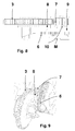
- the figure 14 illustrates the use according to a particular embodiment of a microswitch 11 for providing power to the electric motor M of the gearbox, depending on the position of the control device.
- This micro-contact 11 comprises a pallet 12 adapted to cooperate with a protuberance 14 forming a cam belonging to a wheel 2a integral with the control shaft 2.
- the wheel 2a has on a little less than half of its circumference, a semi-circular recess, the aforementioned protuberance 14 being formed by the portion of the circumference of the wheel 2a complementary to that comprising the recess.
- the control device is armed open position, or closed armed. In this position, the pallet 12 of the microswitch 11 is in the high position, because the pallet 12 is in the recess, which implies that the microswitch 11 is not actuated and therefore, that the electric motor M is not powered.
- control shaft 2 and its associated wheel 2a have rotated at an angle of about 180 ° in the counterclockwise direction, to bring the control device in the closed position disarmed.
- control device On the figure 17 , the control device is being armed and the control shaft 2 and its associated wheel 2a have further rotated by an angle of substantially 180 °, relative to the position of the previous figure.
- a slider may be mechanically connected to the so-called second wheel and allow to actuate a micro-contact during the sliding of the second wheel 6 so as to synchronize the power supply of the electric motor M.
- a device for maintaining the clutch during the closing of the device has been made to eliminate the shocks collected by the clutch release gears during the closure of the device, for example slamming, shock loading. tenons, inertia, etc ... as was the case for an engine with a gear train still engaged with the main shaft of the control device.
- the present invention thus makes it possible to improve the mechanical endurance of the disengagement device of the motorization.
- This device makes it possible to disengage the motorization at the end of arming of the control so as not to damage it prematurely and also to disengage the motorization during the closure of the circuit breaker, so as not to drive the gear train of the engine and damage it and not to disturb the closing of the order.
- This device uses the property that the gears with a profile of right teeth in involute circles do not transmit axial force.
- This device does not use the inertia and kinetic energy of the gears of the motorization produced by the speed of rotation of the shaft and the reduction ratio.
- the invention is not limited to the embodiments described and illustrated which have been given by way of example.
Landscapes
- Connection Of Motors, Electrical Generators, Mechanical Devices, And The Like (AREA)
- Power-Operated Mechanisms For Wings (AREA)
- Mechanisms For Operating Contacts (AREA)
Claims (11)
- Vorrichtung zur Entkupplung der Motorantriebsvorrichtung von der Rückstellvorrichtung der Kontaktschlussvorrichtung in einem elektrischen Schutzschalter, wobei der Schalter mindestens einen Festkontakt und mindestens einen Bewegtkontakt aufweist, der von einer Antriebswelle der Pole getragen wird, wobei die Welle eine erste Position, in der die Kontakte geschlossen sind, und eine zweite Position, in der die Kontakte offen sind, einnehmen kann, und wobei eine Rückstellvorrichtung eine Energieakkumulatorvorrichtung umfasst, die dazu bestimmt ist, am Schließen der Kontakte teilzunehmen, wobei die Entkupplungsvorrichtung Entkupplungsmittel umfasst, die geeignet sind, die Motorantriebsvorrichtung und die Rückstellvorrichtung am Ende des Einstellvorgangs zu entkuppeln, wobei die Antriebswelle (2) in ein als erstes (3) bezeichnetes Rad eingreift, wobei das Rad mit Hilfe einer Zwischenvorrichtung (5) von einem als erstes (4) bezeichneten Ritzel, das zu der Motorantriebsvorrichtung M gehört, während der Rückstellung der Schließvorrichtung mitgeführt wird und am Ende des Rückstellvorgangs und während im Wesentlichen des gesamten Vorgangs des Kontaktschlusses nicht mehr mechanisch mit diesem Ritzel (4) verbunden ist, wobei die Zwischenvorrichtung (5) ein als zweites (6) bezeichnetes Zahnrad umfasst, in das in Drehung ein als zweites (7) bezeichnetes Ritzel eingreift, wobei das als zweites (6) bezeichnete Zahnrad mit dem als erstes (4) bezeichneten Ritzel der Motorantriebsvorrichtung M in Eingriff steht, wenn das als zweites (7) bezeichnete Ritzel mit dem als erstes bezeichneten Zahnrad (3) einstückig mit der Antriebswelle (2) in Eingriff steht, wobei diese Entkupplungsmittel Mittel zur axialen Verschiebung des als zweites (6) bezeichneten Rads zwischen einer ersten Position, in der die Motorantriebsvorrichtung M von der Rückstellvorrichtung R entkuppelt ist, und einer zweiten Position, in der diese beiden Vorrichtungen gekuppelt sind, sowie Rückholmittel umfassen, die geeignet sind, das zweite Rad (6) in die zweite Position am Ende des Schließvorgangs zurückzuholen, und wobei diese Mittel zur axialen Verschiebung des als zweites (6) bezeichneten Rads eine Ausbauchung (8) umfassen, die auf dem als erstes (3) bezeichneten Rad bereitgestellt ist und mit einer Ausbauchung (9) zusammenwirkt, die auf dem als zweites (6) bezeichneten Rad bereitgestellt ist,
dadurch gekennzeichnet, dass eine (9) der Ausbauchungen einen Entkupplungskegel umfasst, während die andere (8) der Ausbauchungen einen ringförmigen Sektor umfasst, dessen Länge im Wesentlichen dem Verlauf des Schließens der Antriebswelle (2) entspricht, um die Entkupplung im Wesentlichen während des gesamten Schließvorgangs der Antriebswelle (2) aufrechtzuerhalten. - Entkupplungsvorrichtung nach Anspruch 1, dadurch gekennzeichnet, dass die Antriebswelle (2) die Rückstellvorrichtung R steuert.
- Entkupplungsvorrichtung nach Anspruch 1 oder 2, dadurch gekennzeichnet, dass das als erstes bezeichnete Zahnrad und das als erstes (4) bezeichnete Ritzel in Drehung um zwei zueinander parallele Achsen montiert sind.
- Entkupplungsvorrichtung nach einem der Ansprüche 1 bis 3, dadurch gekennzeichnet, dass das als zweites (6) bezeichnete Rad und sein als zweites (7) bezeichnetes zugeordnetes Ritzel nur ein und dasselbe Stück bilden, wobei diese Einheit axial zwischen zwei Positionen während des Zusammenwirkens der beiden Ausbauchungen gleitet, um das als zweites (6) bezeichnete Rad von dem als erstes (4) bezeichneten Ritzel zu entkuppeln oder auch mit diesem zu kuppeln.
- Entkupplungsvorrichtung nach einem der Ansprüche 1 bis 3, dadurch gekennzeichnet, dass das als zweites (6) bezeichnete Rad mechanisch mit seinem als zweites bezeichneten zugeordneten Ritzel (7) mittels einer Kupplungsvorrichtung (10) verbunden ist, die es gestattet, dass das Rad (6) in Bezug auf sein zugeordnetes Ritzel (7) verschoben wird, das, indem es sich verschiebt, außer Eingriff mit diesem gelangt, wobei so die mechanische Verbindung zwischen dem als erstes (3) bezeichneten Rad und dem als erstes (4) bezeichneten Ritzel der Motorantriebsvorrichtung M unterbrochen wird.
- Entkupplungsvorrichtung nach einem der Ansprüche 1 bis 5, dadurch gekennzeichnet, dass diese Mittel zur Aufrechterhaltung der Entkupplung während des Schließens der Kontakte hauptsächlich daraus bestehen, dass die Form und die Länge der Ausbauchungen (8, 9) derart gewählt sind, dass das Zusammenwirken zwischen den beiden Ausbauchungen, das die relative axiale Verschiebung zwischen den beiden Rädern (3, 6) bewirkt, während im Wesentlichen der gesamten Dauer des Schließvorgangs des Schalters andauert.
- Entkupplungsvorrichtung nach Anspruch 1, dadurch gekennzeichnet, dass diese Rückholmittel eine Druckfeder umfassen, die axial um die Achse des zweiten Rads (6) montiert ist und geeignet ist, das Rad in die zweite Position zurückzuholen.
- Entkupplungsvorrichtung nach einem der Ansprüche 1 bis 7, dadurch gekennzeichnet, dass diese einen Schlitten umfasst, der einstückig in Translation mit dem als zweites (6) bezeichneten Rad ausgebildet ist und geeignet ist, einen Mikrokontakt (11) zu betätigen, der elektrisch mit der Versorgungsvorrichtung der Motorantriebsvorrichtung M verbunden ist.
- Entkupplungsvorrichtung nach einem der Ansprüche 1 bis 8, dadurch gekennzeichnet, dass diese einen Mikrokontakt (11) umfasst, wobei der Mikrokontakt (11) eine Palette (12) umfasst, welche geeignet ist, mit einer Ausbauchung (14) zusammenzuwirken, die auf einem Rad (2a) einstückig mit der Antriebswelle (2) bereitgestellt ist.
- Elektrischer Schutzschalter nach einem der vorhergehenden Ansprüche, dadurch gekennzeichnet, dass dieser eine Entkupplungsvorrichtung nach einem der vorhergehenden Ansprüche umfasst.
- Elektrischer Schutzschalter nach Anspruch 10, dadurch gekennzeichnet, dass dieser ein Unterbrecher oder ein elektrischer Überlastschalter mit mittlerer Spannung ist.
Applications Claiming Priority (1)
| Application Number | Priority Date | Filing Date | Title |
|---|---|---|---|
| FR1102977A FR2980909B1 (fr) | 2011-09-30 | 2011-09-30 | Dispositif de debrayage de la motorisation du dispositif de rearmement du dispositif de fermeture des contacts dans un appareil de protection electrique et appareil le comportant |
Publications (2)
| Publication Number | Publication Date |
|---|---|
| EP2575150A1 EP2575150A1 (de) | 2013-04-03 |
| EP2575150B1 true EP2575150B1 (de) | 2016-10-05 |
Family
ID=46881027
Family Applications (1)
| Application Number | Title | Priority Date | Filing Date |
|---|---|---|---|
| EP12306090.7A Active EP2575150B1 (de) | 2011-09-30 | 2012-09-11 | Vorrichtung zur entkupplung des motorantriebs von der federspannvorrichtung des kontaktantriebs in einem schutzschalter und schutzschalter mit einer entsprechenden vorrichtung. |
Country Status (4)
| Country | Link |
|---|---|
| EP (1) | EP2575150B1 (de) |
| CN (1) | CN103035426B (de) |
| ES (1) | ES2608586T3 (de) |
| FR (1) | FR2980909B1 (de) |
Families Citing this family (2)
| Publication number | Priority date | Publication date | Assignee | Title |
|---|---|---|---|---|
| FR2984589A1 (fr) * | 2011-12-16 | 2013-06-21 | Schneider Electric Ind Sas | Dispositif de commande de la motorisation du dispositif de rearmement du dispositif de fermeture des contacts dans un appareil de protection electrique et appareil le comportant |
| DE102016215888A1 (de) * | 2016-08-24 | 2018-03-01 | Siemens Aktiengesellschaft | Koppeleinrichtung und Verfahren zum Koppeln und Entkoppeln eines Spanngetriebes eines Leistungsschalters |
Family Cites Families (6)
| Publication number | Priority date | Publication date | Assignee | Title |
|---|---|---|---|---|
| DE3415501A1 (de) * | 1984-04-26 | 1985-11-07 | Licentia Patent-Verwaltungs-Gmbh, 6000 Frankfurt | Schalterantrieb |
| FR2589626B1 (fr) | 1985-10-31 | 1989-03-03 | Merlin Gerin | Mecanisme de commande d'un disjoncteur equipe d'un systeme accumulateur d'energie |
| JP3644187B2 (ja) * | 1997-04-17 | 2005-04-27 | 三菱電機株式会社 | 遮断器の蓄勢装置 |
| DE19843205A1 (de) * | 1998-09-16 | 2000-03-23 | Siemens Ag | Niederspannungs-Leistungsschalter mit einem nachrüstbaren Motoraufzug |
| FR2807204B1 (fr) | 2000-03-31 | 2002-05-24 | Schneider Electric Ind Sa | Appareillage electrique de coupure multipolaire muni d'un mecanisme d'entrainement et de modules de coupure |
| KR100850422B1 (ko) * | 2007-08-20 | 2008-08-04 | 엘에스산전 주식회사 | 기중차단기의 투입스프링 차징장치 |
-
2011
- 2011-09-30 FR FR1102977A patent/FR2980909B1/fr not_active Expired - Fee Related
-
2012
- 2012-09-11 EP EP12306090.7A patent/EP2575150B1/de active Active
- 2012-09-11 ES ES12306090.7T patent/ES2608586T3/es active Active
- 2012-09-27 CN CN201210365961.3A patent/CN103035426B/zh active Active
Non-Patent Citations (1)
| Title |
|---|
| None * |
Also Published As
| Publication number | Publication date |
|---|---|
| FR2980909A1 (fr) | 2013-04-05 |
| CN103035426B (zh) | 2016-06-08 |
| CN103035426A (zh) | 2013-04-10 |
| ES2608586T3 (es) | 2017-04-12 |
| FR2980909B1 (fr) | 2016-08-05 |
| EP2575150A1 (de) | 2013-04-03 |
Similar Documents
| Publication | Publication Date | Title |
|---|---|---|
| EP1404968B1 (de) | Anlasser für ein kraftfahrzeug | |
| EP3018268B1 (de) | Entkuppelbarer mechanismus für motorisierte schliessvorrichtung vom typ schliesszylinder mit druckknopf | |
| EP2073228B1 (de) | Kompakte, robuste Steuerung für elektrische Mittel- und Hochspannungsgeräte | |
| FR2458654A1 (fr) | Mecanisme de commande pour un dispositif de fermeture et/ou de verrouillage d'une porte de vehicule | |
| EP2602804B1 (de) | Betätigungsvorrichtung für die Pole in einer elektrischen Mittelspannungsbetätigungseinrichtung | |
| EP2605256B1 (de) | Vorrichtung zur Steuerung der Resetvorrichtungs-Motorisierung der Kontaktschließvorrichtung in einem elektrischen Schutzgerät, und eine solche Vorrichtung enthaltendes Gerät | |
| EP2842143B1 (de) | Steuerung von feder(n) für einen hoch- oder mittelspannungsschutzschalter mit einer klinken-freilaufkopplungsvorrichtung | |
| EP2575150B1 (de) | Vorrichtung zur entkupplung des motorantriebs von der federspannvorrichtung des kontaktantriebs in einem schutzschalter und schutzschalter mit einer entsprechenden vorrichtung. | |
| EP1706880A1 (de) | Steuerung für eine elektrische stromunterbrechereinrichtung | |
| EP2377139B1 (de) | Vorrichtung zur fernbetätigung und damit versehener schutzschalter | |
| EP1769154B1 (de) | Anlassermotor, insbesondere für ein kraftfahrzeug, ausgestattet mit einem freilaufendem reibanlasser | |
| EP2917557A1 (de) | Reibungsstarterantriebseinheit für den eingriff mit einem anlasserzahnkranz einer wärmekraftmaschine und entsprechender wärmekraftmaschinenanlasser | |
| EP1993115B1 (de) | Steuervorrichtung zur Kontaktherstellung oder -unterbrechung zwischen zwei Teilen und mit dieser Vorrichtung ausgestattetes elektrisches Gerät | |
| EP1412651B1 (de) | Verbindungsvorrichtung für kupplungsmuffe | |
| EP2984329A2 (de) | Anlasser mit einem antriebsmechanismus mit einem zwischenelement zur verminderung der reibung zwischen einem steuerhebel und einem fahrer | |
| FR3004222A1 (fr) | Ensemble porte-pignon perfectionne, lanceur, et demarreur pour vehicule automobile correspondants | |
| EP2865882A1 (de) | Startgerät mit perfektionierter Reibungskupplung, und entsprechender Anlasser eines Kraftfahrzeug-Verbrennungsmotors | |
| FR2827341A1 (fr) | Demarreur pour vehicule automobile | |
| FR2563654A1 (fr) | Commande d'interrupteur electrique a roue et vis sans fin et accumulation d'energie par ressort | |
| EP2239456B1 (de) | Anlassvorrichtung für Verbrennungsmotor, insbesondere von Kraftfahrzeugen | |
| FR2551914A1 (fr) | Auxiliaire de telecommande pour enclenchement a distance d'un disjoncteur a prehenseur d'enclenchement et de declenchement | |
| FR3003307A1 (fr) | Demarreur a lanceur muni d'un embrayage a friction a double leviers de commande | |
| FR2485128A1 (fr) | Embrayage et dispositif de condamnation electrique centralisee des serrures d'un vehicule automobile mettant en oeuvre ledit embrayage | |
| EP2875236A2 (de) | Anlasser mit einem scheibenkupplungssystem mit einem anschlag zur aktivierung des kupplungssystems | |
| FR2996604A1 (fr) | Demarreur a lanceur muni d'elements rotatifs de reduction de frottement entre un levier de commande et un entraineur, et levier de commande correspondant |
Legal Events
| Date | Code | Title | Description |
|---|---|---|---|
| PUAI | Public reference made under article 153(3) epc to a published international application that has entered the european phase |
Free format text: ORIGINAL CODE: 0009012 |
|
| AK | Designated contracting states |
Kind code of ref document: A1 Designated state(s): AL AT BE BG CH CY CZ DE DK EE ES FI FR GB GR HR HU IE IS IT LI LT LU LV MC MK MT NL NO PL PT RO RS SE SI SK SM TR |
|
| AX | Request for extension of the european patent |
Extension state: BA ME |
|
| 17P | Request for examination filed |
Effective date: 20130419 |
|
| GRAP | Despatch of communication of intention to grant a patent |
Free format text: ORIGINAL CODE: EPIDOSNIGR1 |
|
| RIC1 | Information provided on ipc code assigned before grant |
Ipc: H01H 3/30 20060101AFI20160513BHEP Ipc: H01H 3/58 20060101ALI20160513BHEP |
|
| INTG | Intention to grant announced |
Effective date: 20160617 |
|
| RIN1 | Information on inventor provided before grant (corrected) |
Inventor name: TAMISIER, DIDIER |
|
| GRAS | Grant fee paid |
Free format text: ORIGINAL CODE: EPIDOSNIGR3 |
|
| GRAA | (expected) grant |
Free format text: ORIGINAL CODE: 0009210 |
|
| AK | Designated contracting states |
Kind code of ref document: B1 Designated state(s): AL AT BE BG CH CY CZ DE DK EE ES FI FR GB GR HR HU IE IS IT LI LT LU LV MC MK MT NL NO PL PT RO RS SE SI SK SM TR |
|
| REG | Reference to a national code |
Ref country code: GB Ref legal event code: FG4D Free format text: NOT ENGLISH |
|
| REG | Reference to a national code |
Ref country code: CH Ref legal event code: EP |
|
| REG | Reference to a national code |
Ref country code: AT Ref legal event code: REF Ref document number: 835257 Country of ref document: AT Kind code of ref document: T Effective date: 20161015 |
|
| REG | Reference to a national code |
Ref country code: IE Ref legal event code: FG4D Free format text: LANGUAGE OF EP DOCUMENT: FRENCH |
|
| REG | Reference to a national code |
Ref country code: DE Ref legal event code: R096 Ref document number: 602012023695 Country of ref document: DE |
|
| REG | Reference to a national code |
Ref country code: NL Ref legal event code: MP Effective date: 20161005 |
|
| REG | Reference to a national code |
Ref country code: LT Ref legal event code: MG4D |
|
| PG25 | Lapsed in a contracting state [announced via postgrant information from national office to epo] |
Ref country code: LV Free format text: LAPSE BECAUSE OF FAILURE TO SUBMIT A TRANSLATION OF THE DESCRIPTION OR TO PAY THE FEE WITHIN THE PRESCRIBED TIME-LIMIT Effective date: 20161005 |
|
| REG | Reference to a national code |
Ref country code: AT Ref legal event code: MK05 Ref document number: 835257 Country of ref document: AT Kind code of ref document: T Effective date: 20161005 |
|
| REG | Reference to a national code |
Ref country code: ES Ref legal event code: FG2A Ref document number: 2608586 Country of ref document: ES Kind code of ref document: T3 Effective date: 20170412 |
|
| PG25 | Lapsed in a contracting state [announced via postgrant information from national office to epo] |
Ref country code: SE Free format text: LAPSE BECAUSE OF FAILURE TO SUBMIT A TRANSLATION OF THE DESCRIPTION OR TO PAY THE FEE WITHIN THE PRESCRIBED TIME-LIMIT Effective date: 20161005 Ref country code: NO Free format text: LAPSE BECAUSE OF FAILURE TO SUBMIT A TRANSLATION OF THE DESCRIPTION OR TO PAY THE FEE WITHIN THE PRESCRIBED TIME-LIMIT Effective date: 20170105 Ref country code: LT Free format text: LAPSE BECAUSE OF FAILURE TO SUBMIT A TRANSLATION OF THE DESCRIPTION OR TO PAY THE FEE WITHIN THE PRESCRIBED TIME-LIMIT Effective date: 20161005 Ref country code: GR Free format text: LAPSE BECAUSE OF FAILURE TO SUBMIT A TRANSLATION OF THE DESCRIPTION OR TO PAY THE FEE WITHIN THE PRESCRIBED TIME-LIMIT Effective date: 20170106 |
|
| PG25 | Lapsed in a contracting state [announced via postgrant information from national office to epo] |
Ref country code: IS Free format text: LAPSE BECAUSE OF FAILURE TO SUBMIT A TRANSLATION OF THE DESCRIPTION OR TO PAY THE FEE WITHIN THE PRESCRIBED TIME-LIMIT Effective date: 20170205 Ref country code: AT Free format text: LAPSE BECAUSE OF FAILURE TO SUBMIT A TRANSLATION OF THE DESCRIPTION OR TO PAY THE FEE WITHIN THE PRESCRIBED TIME-LIMIT Effective date: 20161005 Ref country code: RS Free format text: LAPSE BECAUSE OF FAILURE TO SUBMIT A TRANSLATION OF THE DESCRIPTION OR TO PAY THE FEE WITHIN THE PRESCRIBED TIME-LIMIT Effective date: 20161005 Ref country code: PT Free format text: LAPSE BECAUSE OF FAILURE TO SUBMIT A TRANSLATION OF THE DESCRIPTION OR TO PAY THE FEE WITHIN THE PRESCRIBED TIME-LIMIT Effective date: 20170206 Ref country code: PL Free format text: LAPSE BECAUSE OF FAILURE TO SUBMIT A TRANSLATION OF THE DESCRIPTION OR TO PAY THE FEE WITHIN THE PRESCRIBED TIME-LIMIT Effective date: 20161005 Ref country code: HR Free format text: LAPSE BECAUSE OF FAILURE TO SUBMIT A TRANSLATION OF THE DESCRIPTION OR TO PAY THE FEE WITHIN THE PRESCRIBED TIME-LIMIT Effective date: 20161005 Ref country code: FI Free format text: LAPSE BECAUSE OF FAILURE TO SUBMIT A TRANSLATION OF THE DESCRIPTION OR TO PAY THE FEE WITHIN THE PRESCRIBED TIME-LIMIT Effective date: 20161005 Ref country code: NL Free format text: LAPSE BECAUSE OF FAILURE TO SUBMIT A TRANSLATION OF THE DESCRIPTION OR TO PAY THE FEE WITHIN THE PRESCRIBED TIME-LIMIT Effective date: 20161005 |
|
| REG | Reference to a national code |
Ref country code: DE Ref legal event code: R097 Ref document number: 602012023695 Country of ref document: DE |
|
| PG25 | Lapsed in a contracting state [announced via postgrant information from national office to epo] |
Ref country code: RO Free format text: LAPSE BECAUSE OF FAILURE TO SUBMIT A TRANSLATION OF THE DESCRIPTION OR TO PAY THE FEE WITHIN THE PRESCRIBED TIME-LIMIT Effective date: 20161005 Ref country code: SK Free format text: LAPSE BECAUSE OF FAILURE TO SUBMIT A TRANSLATION OF THE DESCRIPTION OR TO PAY THE FEE WITHIN THE PRESCRIBED TIME-LIMIT Effective date: 20161005 Ref country code: DK Free format text: LAPSE BECAUSE OF FAILURE TO SUBMIT A TRANSLATION OF THE DESCRIPTION OR TO PAY THE FEE WITHIN THE PRESCRIBED TIME-LIMIT Effective date: 20161005 Ref country code: CZ Free format text: LAPSE BECAUSE OF FAILURE TO SUBMIT A TRANSLATION OF THE DESCRIPTION OR TO PAY THE FEE WITHIN THE PRESCRIBED TIME-LIMIT Effective date: 20161005 Ref country code: EE Free format text: LAPSE BECAUSE OF FAILURE TO SUBMIT A TRANSLATION OF THE DESCRIPTION OR TO PAY THE FEE WITHIN THE PRESCRIBED TIME-LIMIT Effective date: 20161005 |
|
| PLBE | No opposition filed within time limit |
Free format text: ORIGINAL CODE: 0009261 |
|
| STAA | Information on the status of an ep patent application or granted ep patent |
Free format text: STATUS: NO OPPOSITION FILED WITHIN TIME LIMIT |
|
| PG25 | Lapsed in a contracting state [announced via postgrant information from national office to epo] |
Ref country code: BG Free format text: LAPSE BECAUSE OF FAILURE TO SUBMIT A TRANSLATION OF THE DESCRIPTION OR TO PAY THE FEE WITHIN THE PRESCRIBED TIME-LIMIT Effective date: 20170105 Ref country code: IT Free format text: LAPSE BECAUSE OF FAILURE TO SUBMIT A TRANSLATION OF THE DESCRIPTION OR TO PAY THE FEE WITHIN THE PRESCRIBED TIME-LIMIT Effective date: 20161005 Ref country code: SM Free format text: LAPSE BECAUSE OF FAILURE TO SUBMIT A TRANSLATION OF THE DESCRIPTION OR TO PAY THE FEE WITHIN THE PRESCRIBED TIME-LIMIT Effective date: 20161005 |
|
| 26N | No opposition filed |
Effective date: 20170706 |
|
| REG | Reference to a national code |
Ref country code: FR Ref legal event code: PLFP Year of fee payment: 6 |
|
| PG25 | Lapsed in a contracting state [announced via postgrant information from national office to epo] |
Ref country code: SI Free format text: LAPSE BECAUSE OF FAILURE TO SUBMIT A TRANSLATION OF THE DESCRIPTION OR TO PAY THE FEE WITHIN THE PRESCRIBED TIME-LIMIT Effective date: 20161005 |
|
| REG | Reference to a national code |
Ref country code: CH Ref legal event code: PL |
|
| GBPC | Gb: european patent ceased through non-payment of renewal fee |
Effective date: 20170911 |
|
| PG25 | Lapsed in a contracting state [announced via postgrant information from national office to epo] |
Ref country code: MC Free format text: LAPSE BECAUSE OF FAILURE TO SUBMIT A TRANSLATION OF THE DESCRIPTION OR TO PAY THE FEE WITHIN THE PRESCRIBED TIME-LIMIT Effective date: 20161005 |
|
| REG | Reference to a national code |
Ref country code: IE Ref legal event code: MM4A |
|
| REG | Reference to a national code |
Ref country code: BE Ref legal event code: MM Effective date: 20170930 |
|
| PG25 | Lapsed in a contracting state [announced via postgrant information from national office to epo] |
Ref country code: LU Free format text: LAPSE BECAUSE OF NON-PAYMENT OF DUE FEES Effective date: 20170911 |
|
| PG25 | Lapsed in a contracting state [announced via postgrant information from national office to epo] |
Ref country code: CH Free format text: LAPSE BECAUSE OF NON-PAYMENT OF DUE FEES Effective date: 20170930 Ref country code: IE Free format text: LAPSE BECAUSE OF NON-PAYMENT OF DUE FEES Effective date: 20170911 Ref country code: LI Free format text: LAPSE BECAUSE OF NON-PAYMENT OF DUE FEES Effective date: 20170930 Ref country code: GB Free format text: LAPSE BECAUSE OF NON-PAYMENT OF DUE FEES Effective date: 20170911 |
|
| PG25 | Lapsed in a contracting state [announced via postgrant information from national office to epo] |
Ref country code: BE Free format text: LAPSE BECAUSE OF NON-PAYMENT OF DUE FEES Effective date: 20170930 |
|
| REG | Reference to a national code |
Ref country code: FR Ref legal event code: PLFP Year of fee payment: 7 |
|
| PG25 | Lapsed in a contracting state [announced via postgrant information from national office to epo] |
Ref country code: MT Free format text: LAPSE BECAUSE OF FAILURE TO SUBMIT A TRANSLATION OF THE DESCRIPTION OR TO PAY THE FEE WITHIN THE PRESCRIBED TIME-LIMIT Effective date: 20161005 |
|
| PG25 | Lapsed in a contracting state [announced via postgrant information from national office to epo] |
Ref country code: HU Free format text: LAPSE BECAUSE OF FAILURE TO SUBMIT A TRANSLATION OF THE DESCRIPTION OR TO PAY THE FEE WITHIN THE PRESCRIBED TIME-LIMIT; INVALID AB INITIO Effective date: 20120911 |
|
| PG25 | Lapsed in a contracting state [announced via postgrant information from national office to epo] |
Ref country code: CY Free format text: LAPSE BECAUSE OF NON-PAYMENT OF DUE FEES Effective date: 20161005 |
|
| PG25 | Lapsed in a contracting state [announced via postgrant information from national office to epo] |
Ref country code: MK Free format text: LAPSE BECAUSE OF FAILURE TO SUBMIT A TRANSLATION OF THE DESCRIPTION OR TO PAY THE FEE WITHIN THE PRESCRIBED TIME-LIMIT Effective date: 20161005 |
|
| PG25 | Lapsed in a contracting state [announced via postgrant information from national office to epo] |
Ref country code: TR Free format text: LAPSE BECAUSE OF FAILURE TO SUBMIT A TRANSLATION OF THE DESCRIPTION OR TO PAY THE FEE WITHIN THE PRESCRIBED TIME-LIMIT Effective date: 20161005 |
|
| PG25 | Lapsed in a contracting state [announced via postgrant information from national office to epo] |
Ref country code: AL Free format text: LAPSE BECAUSE OF FAILURE TO SUBMIT A TRANSLATION OF THE DESCRIPTION OR TO PAY THE FEE WITHIN THE PRESCRIBED TIME-LIMIT Effective date: 20161005 |
|
| PGFP | Annual fee paid to national office [announced via postgrant information from national office to epo] |
Ref country code: DE Payment date: 20250926 Year of fee payment: 14 |
|
| PGFP | Annual fee paid to national office [announced via postgrant information from national office to epo] |
Ref country code: FR Payment date: 20250925 Year of fee payment: 14 |
|
| PGFP | Annual fee paid to national office [announced via postgrant information from national office to epo] |
Ref country code: ES Payment date: 20251015 Year of fee payment: 14 |