EP2574890B1 - Temperature sensor and hydrogen-filled system - Google Patents
Temperature sensor and hydrogen-filled system Download PDFInfo
- Publication number
- EP2574890B1 EP2574890B1 EP12172728.3A EP12172728A EP2574890B1 EP 2574890 B1 EP2574890 B1 EP 2574890B1 EP 12172728 A EP12172728 A EP 12172728A EP 2574890 B1 EP2574890 B1 EP 2574890B1
- Authority
- EP
- European Patent Office
- Prior art keywords
- lead wires
- alloy
- temperature sensor
- hydrogen
- glass
- Prior art date
- Legal status (The legal status is an assumption and is not a legal conclusion. Google has not performed a legal analysis and makes no representation as to the accuracy of the status listed.)
- Active
Links
Images



Classifications
-
- G—PHYSICS
- G01—MEASURING; TESTING
- G01K—MEASURING TEMPERATURE; MEASURING QUANTITY OF HEAT; THERMALLY-SENSITIVE ELEMENTS NOT OTHERWISE PROVIDED FOR
- G01K7/00—Measuring temperature based on the use of electric or magnetic elements directly sensitive to heat ; Power supply therefor, e.g. using thermoelectric elements
- G01K7/16—Measuring temperature based on the use of electric or magnetic elements directly sensitive to heat ; Power supply therefor, e.g. using thermoelectric elements using resistive elements
- G01K7/22—Measuring temperature based on the use of electric or magnetic elements directly sensitive to heat ; Power supply therefor, e.g. using thermoelectric elements using resistive elements the element being a non-linear resistance, e.g. thermistor
-
- F—MECHANICAL ENGINEERING; LIGHTING; HEATING; WEAPONS; BLASTING
- F17—STORING OR DISTRIBUTING GASES OR LIQUIDS
- F17C—VESSELS FOR CONTAINING OR STORING COMPRESSED, LIQUEFIED OR SOLIDIFIED GASES; FIXED-CAPACITY GAS-HOLDERS; FILLING VESSELS WITH, OR DISCHARGING FROM VESSELS, COMPRESSED, LIQUEFIED, OR SOLIDIFIED GASES
- F17C13/00—Details of vessels or of the filling or discharging of vessels
- F17C13/02—Special adaptations of indicating, measuring, or monitoring equipment
-
- G—PHYSICS
- G01—MEASURING; TESTING
- G01K—MEASURING TEMPERATURE; MEASURING QUANTITY OF HEAT; THERMALLY-SENSITIVE ELEMENTS NOT OTHERWISE PROVIDED FOR
- G01K1/00—Details of thermometers not specially adapted for particular types of thermometer
- G01K1/08—Protective devices, e.g. casings
- G01K1/10—Protective devices, e.g. casings for preventing chemical attack
-
- G—PHYSICS
- G01—MEASURING; TESTING
- G01K—MEASURING TEMPERATURE; MEASURING QUANTITY OF HEAT; THERMALLY-SENSITIVE ELEMENTS NOT OTHERWISE PROVIDED FOR
- G01K7/00—Measuring temperature based on the use of electric or magnetic elements directly sensitive to heat ; Power supply therefor, e.g. using thermoelectric elements
- G01K7/16—Measuring temperature based on the use of electric or magnetic elements directly sensitive to heat ; Power supply therefor, e.g. using thermoelectric elements using resistive elements
-
- Y—GENERAL TAGGING OF NEW TECHNOLOGICAL DEVELOPMENTS; GENERAL TAGGING OF CROSS-SECTIONAL TECHNOLOGIES SPANNING OVER SEVERAL SECTIONS OF THE IPC; TECHNICAL SUBJECTS COVERED BY FORMER USPC CROSS-REFERENCE ART COLLECTIONS [XRACs] AND DIGESTS
- Y02—TECHNOLOGIES OR APPLICATIONS FOR MITIGATION OR ADAPTATION AGAINST CLIMATE CHANGE
- Y02E—REDUCTION OF GREENHOUSE GAS [GHG] EMISSIONS, RELATED TO ENERGY GENERATION, TRANSMISSION OR DISTRIBUTION
- Y02E60/00—Enabling technologies; Technologies with a potential or indirect contribution to GHG emissions mitigation
- Y02E60/30—Hydrogen technology
- Y02E60/32—Hydrogen storage
Definitions
- the present invention relates to a temperature sensor capable of measuring a temperature in a container filled with hydrogen gas.
- a sensor element for temperature detection When a temperature of a hydrogen gas atmosphere is detected, a sensor element for temperature detection may be exposed to hydrogen to be reduced, thereby degrading accuracy of the detected temperature.
- a thermistor a thermally sensitive resistor
- the detected temperature when the resistance value of the sensor element is increased due to reduction with hydrogen, the detected temperature is output as being lower than an actual temperature.
- Japanese Patent Laid-Open No. 2010-266206 proposes that a tank filled with hydrogen is provided with a plurality of temperature sensors and, based on an output from a temperature sensor with a high detected temperature, outputs of the other sensors are corrected. This proposal was made by paying attention to the fact that a sensor element (a temperature sensor) not reduced with hydrogen has a low resistance value and its detected temperature is high.
- JP 2005-294653 relates to a high-temperature thermistor highly accurately and stably available over the temperature range from a room temperature to 700°C.
- a thermistor element is configured by forming electrodes on both upper and lower surfaces of a plate-like metal oxide sintered body 11 composed of Cr, Mn, Ca; and by connecting lead wires to the electrodes.
- the thermistor element and the connecting terminal side portions of the lead wires are fused and sealed by a sealing glass having a specific composition and linear expansion coefficient which is equal or smaller than a linear expansion coefficient of the metal oxide sintered body.
- a hydrogen gas atmosphere can be embodied in, for example, a tank storing hydrogen as a negative electrode active material for a fuel cell.
- the pressure in this tank is set equal to or lower than 35 MPa due to legal regulations, but its upper limit may be further increased to, for example, 70 MPa, in future. Therefore, to address this trend, not only reduction with hydrogen but also exposure to high pressure is required to be taken into consideration.
- an aim is to achieve a sensor element with durability at a pressure of 120 MPa and a temperature of -90°C to 150°C under an atmosphere with a hydrogen concentration of 10%.
- the present invention was made based on these technical problems.
- the present invention relates to the use of a temperature sensor excellent in durability under a high-pressure hydrogen gas atmosphere. Also, another object of the present invention is to provide a hydrogen-filled system including this temperature sensor.
- a temperature sensor used in the present invention includes a thermistor element body comprising an oxide sintered body, a pair of lead wires each electrically connected to the element body, and a glass sealing body sealing the element body and a part of the lead wires including a portion connected to the element body, wherein the pair of lead wires comprising any of Pt, an alloy comprising Pt and one or two of Ir and Pd, and an alloy of Pd and Ir, and the temperature sensor is used under a hydrogen atmosphere.
- the present invention is based on new findings that, by using the lead wires made of a specific material, durability under the hydrogen atmosphere can be significantly improved.
- a content of Ir and Pd in each alloy may be in a range equal to or lower than 20 mass %.
- the content of Ir and Pd in each alloy is preferably 5 mass % to 20 mass %, and more preferably 8 mass % to 12 mass %.
- the temperature sensor of the present invention in a hydrogen-filled system including a container filled with hydrogen and a temperature sensor measuring a temperature in the container, the temperature of hydrogen in the container can be stably measured for a long period of time.
- a temperature sensor excellent in durability under a high-pressure atmosphere of hydrogen can be provided.
- a temperature sensor 10 in a first embodiment is schematically configured of a thermistor element 1 and a sealing glass 2.
- the thermistor element 1 is formed of a semiconductor element having a large temperature coefficient of its electrical resistance value, and is used together with a detection circuit (not shown) for extracting a change in resistance value as a change in voltage, thereby detecting a temperature of an environment where the thermistor element 1 is placed and generating a temperature detection signal comprising an electrical signal.
- the sealing glass 2 seals and holds the thermistor element 1 in a hermetic state, thereby preventing the occurrence of a chemical or mechanical change based on the environmental condition and mechanically protecting the thermistor element 1.
- the thermistor element 1 includes an element body 11, electrodes 12a and 12b, and lead wires 13a and 13b.
- the element body 11 for use is formed by sintering a metal oxide to be in a plate shape.
- a typical example of an oxide sintered body for use as the element body 11 is shown below.
- the present invention is not restricted to the following oxide sintered body.
- the upper limit of temperature is 150°C at best, and therefore an oxide sintered body for high temperatures is not required to be used. Therefore, the present invention has many options of usable metal oxides.
- the oxide sintered body in the present invention has a coefficient of linear expansion of 65 ⁇ 10 -7 /°C to 110 ⁇ 10 -7 /°C (30°C to 700°C, the same applies to the following).
- An oxide sintered body with a manganese oxide (Mn 3 O 4 ) having a typical spinel structure as an NTC (negative temperature coefficient) thermistor as a basic composition can be used as the element body 11.
- An oxide sintered body having a composition of M x Mn 3-x O 4 obtained by adding an M element (one or two or more of Ni, Co, Fe, Cu, Al, and Cr) to the above basic structure can be used as the element body 11. Furthermore, one or two or more of V, B, Ba, Bi, Ca, La, Sb, Sr, Ti, and Zr can be added.
- an oxide sintered body with a composite oxide, such as YCrO 3 , as a basic structure having a typical perovskite structure as a PCT (positive temperature coefficient) thermistor can be used as the element body 11.
- the electrodes 12a and 12b are formed on a front surface and a rear surface, respectively, of the element body 11 in a plate shape.
- the electrodes 12a and 12b are configured of a material selected from gold (Au), platinum (Pt), silver (Ag), and an alloy thereof.
- the lead wires 13a and 13b have their one end connected to the electrodes 12a and 12b, respectively, thereby connecting the thermistor element 1 and an external circuit.
- the material of the lead wires 13a and 13b is selected from Pt, an alloy of Pt and iridium (Ir), an alloy of Pt and palladium (Pd), and an alloy of Pt, Ir, and Pd, with heat resistance.
- a content of Ir and Pd in each alloy is in a range equal to or lower than 20 mass % (hereinafter simply referred to as %).
- a content of Ir and Pd is preferably 5% to 20%, and more preferably 8% to 12%.
- the lead wires 13a and 13b have their ends connected to the electrodes 12a and 12b sealed with the sealing glass 2.
- any of amorphous glass and crystalline glass can be used as the sealing glass 2 shown in FIG. 1A .
- the amorphous glass having a glass softening point in a range of 300°C to 750°C, and the crystalline glass having a crystallization temperature in a range of 700°C to 1000°C can be used.
- the amorphous glass and the crystalline glass preferably have a coefficient of linear expansion of 65 ⁇ 10 -7 /°C to 110 ⁇ 10 -7 /°C in consideration of a coefficient of linear expansion of the oxide sintered body configuring the element body 11.
- SiO 2 -Pbo-based glass or SiO 2 -SrO 2 -based glass can be used as the glass having these characteristics. These are merely examples, and the glass is allowed to further include one or two or more of calcium oxide (CaO), manganese oxide (MnO), and aluminum oxide (Al 2 O 3 ) and to still further include another oxide.
- the temperature sensor 10 has excellent durability under a high-pressure atmosphere of hydrogen. The reason for this assessed by the inventors is as described below.
- the inventors observed a course of occurrence of a deviation in the detection results of the temperature sensor using the thermistor under a hydrogen atmosphere. That is, normally, since the element body formed of a thermistor is sealed with glass, no deviation occurs in the detection results as long as the sealed state is ensured. However, according to the studies by the inventors, a deviation may occur within an extremely short time, and it has been confirmed that the deviation is caused because the sealed state of the element body with the glass is released. In particular, it has been confirmed that with exfoliation occurring at a portion of sealing the lead wires, hydrogen infiltrates the inside of the sealing glass from the exfoliated portion to abruptly reduce the thermistor.
- This exfoliation is thought to be based on a bonding mechanism between the lead wires and the glass.
- the lead wires are made of Dumet wires (copper-coated nickel steel wires), with an oxide with a covalent bonding of copper (Cu), oxygen (O) and silicon (Si) being generated at a bonding interface between the sealing glass and the lead wires, the sealing glass and the lead wires are closely attached together.
- oxygen is removed also from the oxide, and therefore the covalent bonding itself is destroyed, and the bond strength of the interface between the sealing glass and the lead wires is lost.
- the lead wires 13a and 13b are configured of a material selected from Pt, a Pt-Ir alloy, a Pt-Pd alloy, and a Pt-Ir-Pd alloy. Since these materials are chemically stable, no oxide is generated at the interface between the sealing glass and the lead wires, and therefore the bond strength itself is low compared with bonding via an oxide.
- the interface between the sealing glass 2 and the lead wires 13a and 13b can keep a state of being closely attached together.
- the sealing glass 2 has a higher strength compared with resin, even the temperature sensor 10 is placed under high pressure, the state in which the sealing glass 2 seals the lead wires 13a and 13b can be kept.
- predetermined material powder is measured so as to have a predetermined composition, made into a slurry by adding water thereto, and then poured into a pot together with, for example, zirconia balls, for mixing with a ball mill.
- the slurry after mixing is dried by a spray dryer, and the obtained powder is calcined.
- Water is then added to the calcined powder to make the powder into a slurry again, and the slurry is poured into a pot together with zirconia balls for crushing by a ball mill.
- the crushed powder is dried and granulated by spray drying. Note that the calcination temperature is set as appropriate according to the composition.
- a cylinder-shaped ingot preform is fabricated from the powder obtained from the material preparation process, and this ingot preform is sintered. Then, the obtained sintered body is cut and further ground and polished so as to have a necessary thickness, thereby forming a thermistor wafer in a circular shape.
- This thermistor wafer can be annealed in order to stabilize its thermistor characteristics.
- thick or thin electrode films made of, for example, platinum, are formed on upper and lower surfaces of the annealed thermistor wafer.
- the thick-film electrodes are formed by mixing an organic binder or the like into platinum powder to fabricate a paste, coating both of the upper and lower surfaces of the thermistor wafer with the fabricated paste, drying the surfaces, and then sintering the thermistor wafer.
- the thin-film electrodes are formed by vacuum deposition or sputtering.
- the thermistor wafer with the electrodes thus formed is cut by dicing to have desired dimensions, thereby making thermistor chips for use in a glass sealing element.
- thermistor element 1 shown in FIG. 1B .
- a glass tube 15 is placed so as to cover the thermistor element 1 and connection end side of the lead wires 13a and 13b.
- the portion covered with the glass tube 15 is inserted and held in a furnace heated at a predetermined temperature for a predetermined period of time.
- the glass tube 15 is sufficiently molten and is then coagulated, thereby forming the sealing glass 2 sealing the thermistor element 1 and the connection ends of the lead wires 13a and 13b to obtain the temperature sensor 10 of FIG. 1A .
- the temperature sensor 20 is schematically configured of a thermistor element 21, a sealing glass 22, and a sealing complementary body 23.
- the temperature sensor 20 is different from the temperature sensor 10 in including the sealing complementary body 23 and having a different shape of the sealing glass 22, but the thermistor element 21 has a structure identical to that of the thermistor element 1 of the first embodiment, and therefore is not described herein.
- the sealing complementary body 23 is a cylindrical member, including a holding surface 24 by which the sealing glass 22 is held, lead wire insertion holes 25a and 25b through which the lead wires 13a and 13b respectively penetrate in an axial direction, and a draw surface 26 from which the lead wires 13a and 13b are drawn.
- the thermistor element 21 is placed on the holding surface 24 side of the sealing complementary body 23, and the lead wires 13a and 13b penetrate through the lead wire insertion holes 25a and 25b, respectively, to be drawn to the outside of the draw surface 26.
- the sealing complementary body 23 is made of a material having a coefficient of linear expansion approximately equal to that of the lead wires 13a and 13b, and is integrally molten and bonded together with a bottom surface 23b of the sealing glass 22, with the lead wires 13a and 13b being inserted in the lead wire insertion holes 25a and 25b, respectively. Therefore, the sealing complementary body 23 mechanically reinforces the thermistor element 21 and the connection end side of the lead wires 13a and 13b with the thermistor element 21.
- the sealing complementary body 23 can be configured of a material capable of achieving the above-described object, for example, Al 2 O 3 and forsterite (2MgO ⁇ SiO 2 ) made of MgO ⁇ SiO 2 .
- This ceramic has a coefficient of linear expansion on the order of 7.0 ⁇ 10 -6 /°C to 9.6 ⁇ 10 -6 /°C.
- the sealing glass 22 is bonded to the holding surface 24 of the sealing complementary body 23.
- the thickness of the glass around the lead wires 13a and 13b at a sealing end 22e of the sealing glass 22 can be made thicker, compared with the first embodiment. That is, the sealing glass 2 of the temperature sensor 10 of the first embodiment is in an oval shape as shown in FIG. 1A due to its fabrication process, and therefore the thickness of the sealing glass 2 around the lead wires 13a and 13b at a sealing end 2e from which the lead wires 13a and 13b are drawn, in particular, the thickness of the sealing glass 2 outside the oval body, is thin.
- the thickness of the sealing glass 22 outside the lead wires 13a and 13b at the sealing end 22e can be made thick as equivalent to the other portion.
- the sealing complementary body 23 following the sealing end 22e of the sealing glass 22 also has an outer diameter equivalent to or larger than that of the sealing glass 22. Therefore, in the temperature sensor 20 according to the second embodiment, a mechanical strength around the sealing end 22e is large, and therefore resistance under high-pressure exposure to hydrogen is higher than that of the first embodiment.
- a distance between a tip part 11a of the element body 11 and a top part 22a of the sealing glass 22, that is, the thickness of the glass can be increased, and therefore resistance to high pressure is high.
- a positional shift of the thermistor element 1 may occur in the process of melting and coagulating the glass tube 15 and, the sealing glass 2 and the element body 11 may not be able to be coaxially placed. In this case, the thickness of the glass between the tip part 11a of the element body 11 and the top part 22a of the sealing glass 2 is thin.
- the position of the element body 11 can be kept.
- the sealing glass 22 and the element body 11 are coaxially placed, thereby allowing the thickness of the glass between the tip part 11a of the element body 11 and the top part 22a of the sealing glass 22 to be easily ensured to be a maximum thickness.
- a method of manufacturing the temperature sensor 20 of the second embodiment is described below. Note that the method is the same as that of the first embodiment until the thermistor element 21 having the same structure as that of the thermistor element 1 shown in FIG. 1B is fabricated, and therefore the processes subsequent thereto are described below.
- Predetermined positions of the lead wires 13a and 13b of the thermistor element 21 are coated with a paste formed by mixing glass powder having the same composition as that of the sealing glass 22 with an organic binder. This is to fix the lead wires 13a and 13b to the sealing complementary body 23 in the subsequent process as penetrating through the lead wire insertion holes 25a and 25b.
- the lead wires 13a and 13b are caused to penetrate through the lead wire insertion holes 25a and 25b, respectively, of the sealing complementary body 23 to be placed at predetermined positions of the glass paste applied in advance, and then the glass paste is dried for fixing ( FIG. 2B ).
- the glass tube 15 is prepared, one cut surface of the glass tube 15 is thinly coated with the same glass paste as that used for coating the lead wires 13a and 13b, and then the glass tube 15 is caused to abut on the holding surface 24 of the sealing complementary body 23 so that the paste-coated surface is in contact therewith.
- portions of the glass tube 15 and the sealing complementary body 23 are heated in a heating furnace to melt the glass tube 15, thereby achieving glass sealing of the thermistor element 1 and the lead wires 13a and 13b to form the sealing glass 22. Also, by welding one end of the sealing glass 22 to the holding surface 24 of the sealing complementary body 23, the temperature sensor 20 shown in FIG. 2A is fabricated.
- the temperature sensor 30 is schematically configured of a thermistor element 31 and a sealing glass 32.
- the element body 11, the lead wires 13a and 13b, and the sealing glass 32 are similar in configuration to the element body 11, the lead wires 13a and 13b, and the sealing glass 2 of the first embodiment.
- the lead wires 13a and 13b are drawn from the element body 11 in the same direction in the first embodiment
- the lead wires 13a and 13b are drawn from the element body 11 in different directions in the third embodiment, as shown in FIG. 3 .
- a symmetrical shape is formed with reference to the element body 11, thereby achieving an improvement in dynamical balance.
- a Pd alloy for example, a Pd-18% Ir alloy
- the lead wires 13a and 13b of a Pd alloy is at a price on the order of one third of a Pt alloy, which is a large advantage in cost.
- the element body 11 becomes less prone to be deviated in position when the sealing glass 32 is provided, and a portion of the glass with a thin thickness is less prone to occur.
- a hydrogen-filled system 100 using the temperature sensor 10 (or 20 or 30) described above is described as a fourth embodiment.
- the hydrogen-filled system 100 includes a tank 101 with a pressure-resistant structure for filling with hydrogen, a supply tube 102 including a gas flow passage for filling the tank 101 with hydrogen, a discharge tube 103 for discharging the hydrogen filled in the tank 101 to outside, the temperature sensor 10 (or 20 or 30) detecting a temperature in the tank 101, a pressure sensor 104 detecting a pressure in the tank 101, a remaining amount calculating part 105 finding an amount of hydrogen remaining in the tank 101 based on the measured temperature output from the temperature sensor 10 and the measured pressure output from the pressure sensor 104, and a display part 106 displaying the calculated remaining amount of hydrogen.
- the remaining amount calculating part 105 applies the detected temperature and pressure in the tank 101 to the Boyle-Charles law to find the amount (volume) of hydrogen remaining in the tank 101, next finds a ratio of the remaining amount with respect to a filling limit of the tank 101 (a so-called fill-up), and then causes the found ratio to be displayed on the display part 106.
- the hydrogen-filled system 100 described above is mounted on, for example, an electric vehicle, with a fuel cell as a power source.
- the tank 101 is filled with hydrogen via the supply tube 102 at a gas station.
- the remaining amount calculating part 105 finds the amount of hydrogen remaining in the tank 101, and causes the remaining amount to be displayed on the display part 106.
- the display part 106 is placed inside the vehicle, and a driver drives the vehicle while keeping track of the remaining amount of hydrogen displayed on the display part 106.
- only one tank 101 is shown, but a plurality of tanks 101 may be mounted. In that case, the hydrogen-filled system 100 is provided according to the number of tanks 101.
- the temperature sensor 10 is excellent in durability even under high-pressure exposure to hydrogen, the remaining amount of hydrogen in the tank 101 can be accurately found for a long period of time.
- the temperature sensors 10, 20, and 30 of the embodiments described above were fabricated, and were exposed under an atmosphere with a hydrogen pressure of 120 MPa at 10°C. Then, while a current of 100 ⁇ A was being passed through the temperature sensors, their electrical resistances were measured. As a comparison, a temperature sensor similar to the temperature sensor 10 shown in the first embodiment except that Dumet wires were used as lead wires was used to perform similar measurements. The results are shown in FIG. 5.
- FIG. 5 shows rates of change in electrical resistance with reference to an electrical resistance at 25°C.
- Element body 80% Y-8% Cr-8% Mn-4% Ca (mol %)
- the temperature sensors 10, 20, and 30 according to the present invention were excellent, with fluctuations in resistance value hardly occurring even with a lapse of fifty hours or so.
Landscapes
- Physics & Mathematics (AREA)
- General Physics & Mathematics (AREA)
- Nonlinear Science (AREA)
- Engineering & Computer Science (AREA)
- Mechanical Engineering (AREA)
- General Engineering & Computer Science (AREA)
- Measuring Temperature Or Quantity Of Heat (AREA)
- Thermistors And Varistors (AREA)
Description
- The present invention relates to a temperature sensor capable of measuring a temperature in a container filled with hydrogen gas.
- When a temperature of a hydrogen gas atmosphere is detected, a sensor element for temperature detection may be exposed to hydrogen to be reduced, thereby degrading accuracy of the detected temperature. For example, in a thermistor (a thermally sensitive resistor) for use as a sensor element, when the resistance value of the sensor element is increased due to reduction with hydrogen, the detected temperature is output as being lower than an actual temperature.
- To address the problem of a deviation in the detected temperature due to reduction under a hydrogen gas atmosphere,
Japanese Patent Laid-Open No. 2010-266206 -
JP 2005-294653 body 11 composed of Cr, Mn, Ca; and by connecting lead wires to the electrodes. The thermistor element and the connecting terminal side portions of the lead wires are fused and sealed by a sealing glass having a specific composition and linear expansion coefficient which is equal or smaller than a linear expansion coefficient of the metal oxide sintered body. - The proposal of the patent gazette described above, however, is based on the premises that the temperature sensor is provided to each different tanks. If the sensor elements of all of the temperature sensors are reduced to the same degree, correction cannot be made. Therefore, a problem to be solved with priority is to suppress degradation in characteristics of the sensor element configuring the temperature sensor under a hydrogen gas atmosphere.
- As shown also in the patent gazette described above, a hydrogen gas atmosphere can be embodied in, for example, a tank storing hydrogen as a negative electrode active material for a fuel cell. Under present circumstances, the pressure in this tank is set equal to or lower than 35 MPa due to legal regulations, but its upper limit may be further increased to, for example, 70 MPa, in future. Therefore, to address this trend, not only reduction with hydrogen but also exposure to high pressure is required to be taken into consideration. For example, an aim is to achieve a sensor element with durability at a pressure of 120 MPa and a temperature of -90°C to 150°C under an atmosphere with a hydrogen concentration of 10%.
- The present invention was made based on these technical problems. The present invention relates to the use of a temperature sensor excellent in durability under a high-pressure hydrogen gas atmosphere. Also, another object of the present invention is to provide a hydrogen-filled system including this temperature sensor.
- A temperature sensor used in the present invention includes a thermistor element body comprising an oxide sintered body, a pair of lead wires each electrically connected to the element body, and a glass sealing body sealing the element body and a part of the lead wires including a portion connected to the element body, wherein the pair of lead wires comprising any of Pt, an alloy comprising Pt and one or two of Ir and Pd, and an alloy of Pd and Ir, and the temperature sensor is used under a hydrogen atmosphere.
- The present invention is based on new findings that, by using the lead wires made of a specific material, durability under the hydrogen atmosphere can be significantly improved.
- In the present invention, a content of Ir and Pd in each alloy may be in a range equal to or lower than 20 mass %. The content of Ir and Pd in each alloy is preferably 5 mass % to 20 mass %, and more preferably 8 mass % to 12 mass %.
- By using the temperature sensor of the present invention in a hydrogen-filled system including a container filled with hydrogen and a temperature sensor measuring a temperature in the container, the temperature of hydrogen in the container can be stably measured for a long period of time.
- According to the present invention, a temperature sensor excellent in durability under a high-pressure atmosphere of hydrogen can be provided.
-
-
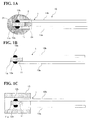
FIGS. 1A, 1B, and 1C are diagrams showing a schematic structure of a temperature sensor according to a first embodiment; -
FIGS. 2A, 2B, and 2C are diagrams showing a schematic structure of a temperature sensor according to a second embodiment; -
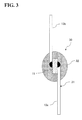
FIG. 3 is a diagram showing a schematic structure of a temperature sensor according to a third embodiment; -
FIG. 4 is diagram showing a schematic structure of a hydrogen-filled system; and -
FIG. 5 is a graph showing results of an experiment. - The present invention is described in detail below based on embodiments shown in the attached drawings.
- As shown in
FIG. 1A , atemperature sensor 10 in a first embodiment is schematically configured of a thermistor element 1 and asealing glass 2. - The thermistor element 1 is formed of a semiconductor element having a large temperature coefficient of its electrical resistance value, and is used together with a detection circuit (not shown) for extracting a change in resistance value as a change in voltage, thereby detecting a temperature of an environment where the thermistor element 1 is placed and generating a temperature detection signal comprising an electrical signal.
- The sealing
glass 2 seals and holds the thermistor element 1 in a hermetic state, thereby preventing the occurrence of a chemical or mechanical change based on the environmental condition and mechanically protecting the thermistor element 1. - The thermistor element 1 includes an
element body 11,electrodes lead wires - The
element body 11 for use is formed by sintering a metal oxide to be in a plate shape. - A typical example of an oxide sintered body for use as the
element body 11 is shown below. However, the present invention is not restricted to the following oxide sintered body. In a storage tank for hydrogen gas (hereinafter simply referred to as hydrogen) aimed by the present invention, the upper limit of temperature is 150°C at best, and therefore an oxide sintered body for high temperatures is not required to be used. Therefore, the present invention has many options of usable metal oxides. The oxide sintered body in the present invention has a coefficient of linear expansion of 65×10-7/°C to 110×10-7/°C (30°C to 700°C, the same applies to the following). - An oxide sintered body with a manganese oxide (Mn3O4) having a typical spinel structure as an NTC (negative temperature coefficient) thermistor as a basic composition can be used as the
element body 11. An oxide sintered body having a composition of MxMn3-xO4 obtained by adding an M element (one or two or more of Ni, Co, Fe, Cu, Al, and Cr) to the above basic structure can be used as theelement body 11. Furthermore, one or two or more of V, B, Ba, Bi, Ca, La, Sb, Sr, Ti, and Zr can be added. - Also, an oxide sintered body with a composite oxide, such as YCrO3, as a basic structure having a typical perovskite structure as a PCT (positive temperature coefficient) thermistor can be used as the
element body 11. - The
electrodes element body 11 in a plate shape. Theelectrodes - The
lead wires electrodes lead wires lead wires electrodes sealing glass 2. - Also, any of amorphous glass and crystalline glass can be used as the
sealing glass 2 shown inFIG. 1A . The amorphous glass having a glass softening point in a range of 300°C to 750°C, and the crystalline glass having a crystallization temperature in a range of 700°C to 1000°C can be used. The amorphous glass and the crystalline glass preferably have a coefficient of linear expansion of 65×10-7/°C to 110×10-7/°C in consideration of a coefficient of linear expansion of the oxide sintered body configuring theelement body 11. As the glass having these characteristics, SiO2-Pbo-based glass or SiO2-SrO2-based glass can be used. These are merely examples, and the glass is allowed to further include one or two or more of calcium oxide (CaO), manganese oxide (MnO), and aluminum oxide (Al2O3) and to still further include another oxide. - Meanwhile, with the material of the
lead wires glass 2 sealing the thermistor element 1 to keep a hermetic state, thetemperature sensor 10 has excellent durability under a high-pressure atmosphere of hydrogen. The reason for this assessed by the inventors is as described below. - The inventors observed a course of occurrence of a deviation in the detection results of the temperature sensor using the thermistor under a hydrogen atmosphere. That is, normally, since the element body formed of a thermistor is sealed with glass, no deviation occurs in the detection results as long as the sealed state is ensured. However, according to the studies by the inventors, a deviation may occur within an extremely short time, and it has been confirmed that the deviation is caused because the sealed state of the element body with the glass is released. In particular, it has been confirmed that with exfoliation occurring at a portion of sealing the lead wires, hydrogen infiltrates the inside of the sealing glass from the exfoliated portion to abruptly reduce the thermistor. This exfoliation is thought to be based on a bonding mechanism between the lead wires and the glass. When the lead wires are made of Dumet wires (copper-coated nickel steel wires), with an oxide with a covalent bonding of copper (Cu), oxygen (O) and silicon (Si) being generated at a bonding interface between the sealing glass and the lead wires, the sealing glass and the lead wires are closely attached together. However, under an atmosphere of hydrogen, oxygen is removed also from the oxide, and therefore the covalent bonding itself is destroyed, and the bond strength of the interface between the sealing glass and the lead wires is lost. Also with involvement of the fact that the temperature sensor is under a high pressure, this bond destruction proceeds to the inside of the sealing glass within a short period of time and, eventually, exposure to hydrogen reaches to the element body (thermistor), thereby causing a deviation in detection. To prevent this problem, in the present embodiment, the
lead wires glass 2 and thelead wires glass 2 has a higher strength compared with resin, even thetemperature sensor 10 is placed under high pressure, the state in which the sealingglass 2 seals thelead wires - A general outline of a method of manufacturing the
temperature sensor 10 is described below. - First, as for the
element body 11 forming the thermistor element 1, predetermined material powder is measured so as to have a predetermined composition, made into a slurry by adding water thereto, and then poured into a pot together with, for example, zirconia balls, for mixing with a ball mill. - Next, the slurry after mixing is dried by a spray dryer, and the obtained powder is calcined. Water is then added to the calcined powder to make the powder into a slurry again, and the slurry is poured into a pot together with zirconia balls for crushing by a ball mill. The crushed powder is dried and granulated by spray drying. Note that the calcination temperature is set as appropriate according to the composition.
- Next, by cold isostatic pressure pressing, a cylinder-shaped ingot preform is fabricated from the powder obtained from the material preparation process, and this ingot preform is sintered. Then, the obtained sintered body is cut and further ground and polished so as to have a necessary thickness, thereby forming a thermistor wafer in a circular shape.
- This thermistor wafer can be annealed in order to stabilize its thermistor characteristics. On upper and lower surfaces of the annealed thermistor wafer, thick or thin electrode films made of, for example, platinum, are formed. The thick-film electrodes are formed by mixing an organic binder or the like into platinum powder to fabricate a paste, coating both of the upper and lower surfaces of the thermistor wafer with the fabricated paste, drying the surfaces, and then sintering the thermistor wafer. On the other hand, the thin-film electrodes are formed by vacuum deposition or sputtering.
- The thermistor wafer with the electrodes thus formed is cut by dicing to have desired dimensions, thereby making thermistor chips for use in a glass sealing element.
- Then, a pair of straight lead wires each having a tip coated with a platinum paste in advance is connected to the upper and lower electrodes of a thermistor chip. After the platinum paste is dried, sintering is performed, thereby obtaining the thermistor element 1 shown in
FIG. 1B . - Next, as shown in
FIG. 1C , aglass tube 15 is placed so as to cover the thermistor element 1 and connection end side of thelead wires glass tube 15 is inserted and held in a furnace heated at a predetermined temperature for a predetermined period of time. During this holding, theglass tube 15 is sufficiently molten and is then coagulated, thereby forming the sealingglass 2 sealing the thermistor element 1 and the connection ends of thelead wires temperature sensor 10 ofFIG. 1A . - Next, a
temperature sensor 20 according to a second embodiment is described. - As shown in
FIG. 2A, 2B, and 2C , thetemperature sensor 20 is schematically configured of athermistor element 21, a sealingglass 22, and a sealingcomplementary body 23. Thetemperature sensor 20 is different from thetemperature sensor 10 in including the sealingcomplementary body 23 and having a different shape of the sealingglass 22, but thethermistor element 21 has a structure identical to that of the thermistor element 1 of the first embodiment, and therefore is not described herein. - The sealing
complementary body 23 is a cylindrical member, including a holdingsurface 24 by which the sealingglass 22 is held, leadwire insertion holes lead wires draw surface 26 from which thelead wires - The
thermistor element 21 is placed on the holdingsurface 24 side of the sealingcomplementary body 23, and thelead wires wire insertion holes draw surface 26. - The sealing
complementary body 23 is made of a material having a coefficient of linear expansion approximately equal to that of thelead wires glass 22, with thelead wires wire insertion holes complementary body 23 mechanically reinforces thethermistor element 21 and the connection end side of thelead wires thermistor element 21. - The sealing
complementary body 23 can be configured of a material capable of achieving the above-described object, for example, Al2O3 and forsterite (2MgO·SiO2) made of MgO·SiO2. This ceramic has a coefficient of linear expansion on the order of 7.0×10⁻⁶/°C to 9.6×10⁻⁶/°C. - Also, as will be described further below, with the provision of the sealing
complementary body 23, durability of thetemperature sensor 20 under high-pressure exposure to hydrogen can be improved more, compared with thetemperature sensor 10 of the first embodiment. - The sealing
glass 22 is bonded to the holdingsurface 24 of the sealingcomplementary body 23. For this reason, the thickness of the glass around thelead wires end 22e of the sealingglass 22 can be made thicker, compared with the first embodiment. That is, the sealingglass 2 of thetemperature sensor 10 of the first embodiment is in an oval shape as shown inFIG. 1A due to its fabrication process, and therefore the thickness of the sealingglass 2 around thelead wires end 2e from which thelead wires glass 2 outside the oval body, is thin. By comparison, in the second embodiment, the thickness of the sealingglass 22 outside thelead wires end 22e can be made thick as equivalent to the other portion. Moreover, the sealingcomplementary body 23 following the sealingend 22e of the sealingglass 22 also has an outer diameter equivalent to or larger than that of the sealingglass 22. Therefore, in thetemperature sensor 20 according to the second embodiment, a mechanical strength around the sealingend 22e is large, and therefore resistance under high-pressure exposure to hydrogen is higher than that of the first embodiment. - Next, in the
temperature sensor 20, ideally, if the sealingglass 22 and theelement body 11 are coaxially placed, a distance between atip part 11a of theelement body 11 and atop part 22a of the sealingglass 22, that is, the thickness of the glass, can be increased, and therefore resistance to high pressure is high. However, in thetemperature sensor 10 of the first embodiment, a positional shift of the thermistor element 1 may occur in the process of melting and coagulating theglass tube 15 and, the sealingglass 2 and theelement body 11 may not be able to be coaxially placed. In this case, the thickness of the glass between thetip part 11a of theelement body 11 and thetop part 22a of the sealingglass 2 is thin. By contrast, in thetemperature sensor 20 of the second embodiment, by fixing the position of the sealingcomplementary body 23 in which thelead wires wire insertion holes element body 11 can be kept. To this end, the sealingglass 22 and theelement body 11 are coaxially placed, thereby allowing the thickness of the glass between thetip part 11a of theelement body 11 and thetop part 22a of the sealingglass 22 to be easily ensured to be a maximum thickness. - A method of manufacturing the
temperature sensor 20 of the second embodiment is described below. Note that the method is the same as that of the first embodiment until thethermistor element 21 having the same structure as that of the thermistor element 1 shown inFIG. 1B is fabricated, and therefore the processes subsequent thereto are described below. - Predetermined positions of the
lead wires thermistor element 21 are coated with a paste formed by mixing glass powder having the same composition as that of the sealingglass 22 with an organic binder. This is to fix thelead wires complementary body 23 in the subsequent process as penetrating through the leadwire insertion holes - Next, the
lead wires wire insertion holes complementary body 23 to be placed at predetermined positions of the glass paste applied in advance, and then the glass paste is dried for fixing (FIG. 2B ). - Then, as shown in
FIG. 2C , theglass tube 15 is prepared, one cut surface of theglass tube 15 is thinly coated with the same glass paste as that used for coating thelead wires glass tube 15 is caused to abut on the holdingsurface 24 of the sealingcomplementary body 23 so that the paste-coated surface is in contact therewith. - Next, with the
lead wires glass tube 15 and the sealingcomplementary body 23 are heated in a heating furnace to melt theglass tube 15, thereby achieving glass sealing of the thermistor element 1 and thelead wires glass 22. Also, by welding one end of the sealingglass 22 to the holdingsurface 24 of the sealingcomplementary body 23, thetemperature sensor 20 shown inFIG. 2A is fabricated. - Next, a
temperature sensor 30 according to a third embodiment is described. - As shown in
FIG. 3 , thetemperature sensor 30 is schematically configured of athermistor element 31 and a sealingglass 32. Theelement body 11, thelead wires glass 32 are similar in configuration to theelement body 11, thelead wires glass 2 of the first embodiment. However, while thelead wires element body 11 in the same direction in the first embodiment, thelead wires element body 11 in different directions in the third embodiment, as shown inFIG. 3 . - In the
temperature sensor 30, with thelead wires element body 11 in different directions, a symmetrical shape is formed with reference to theelement body 11, thereby achieving an improvement in dynamical balance. According to such configuration, it has been confirmed by the inventors that a Pd alloy (for example, a Pd-18% Ir alloy) having a relatively large coefficient of linear expansion of 120×10-7/°C can be used for thelead wires lead wires - Also, with the symmetrical shape with reference to the
element body 11, theelement body 11 becomes less prone to be deviated in position when the sealingglass 32 is provided, and a portion of the glass with a thin thickness is less prone to occur. - A hydrogen-filled
system 100 using the temperature sensor 10 (or 20 or 30) described above is described as a fourth embodiment. - As shown in
FIG. 4 , the hydrogen-filledsystem 100 includes atank 101 with a pressure-resistant structure for filling with hydrogen, asupply tube 102 including a gas flow passage for filling thetank 101 with hydrogen, adischarge tube 103 for discharging the hydrogen filled in thetank 101 to outside, the temperature sensor 10 (or 20 or 30) detecting a temperature in thetank 101, apressure sensor 104 detecting a pressure in thetank 101, a remainingamount calculating part 105 finding an amount of hydrogen remaining in thetank 101 based on the measured temperature output from thetemperature sensor 10 and the measured pressure output from thepressure sensor 104, and adisplay part 106 displaying the calculated remaining amount of hydrogen. - The remaining
amount calculating part 105 applies the detected temperature and pressure in thetank 101 to the Boyle-Charles law to find the amount (volume) of hydrogen remaining in thetank 101, next finds a ratio of the remaining amount with respect to a filling limit of the tank 101 (a so-called fill-up), and then causes the found ratio to be displayed on thedisplay part 106. - The hydrogen-filled
system 100 described above is mounted on, for example, an electric vehicle, with a fuel cell as a power source. In this case, thetank 101 is filled with hydrogen via thesupply tube 102 at a gas station. During travelling, the remainingamount calculating part 105 finds the amount of hydrogen remaining in thetank 101, and causes the remaining amount to be displayed on thedisplay part 106. Thedisplay part 106 is placed inside the vehicle, and a driver drives the vehicle while keeping track of the remaining amount of hydrogen displayed on thedisplay part 106. Here, only onetank 101 is shown, but a plurality oftanks 101 may be mounted. In that case, the hydrogen-filledsystem 100 is provided according to the number oftanks 101. - According to the hydrogen-filled
system 100 described above, thetemperature sensor 10 is excellent in durability even under high-pressure exposure to hydrogen, the remaining amount of hydrogen in thetank 101 can be accurately found for a long period of time. - The
temperature sensors temperature sensor 10 shown in the first embodiment except that Dumet wires were used as lead wires was used to perform similar measurements. The results are shown inFIG. 5. FIG. 5 shows rates of change in electrical resistance with reference to an electrical resistance at 25°C. - Specifications of the
element body 11, thelead wires glass 2 are as follows. Element body: 80% Y-8% Cr-8% Mn-4% Ca (mol %) - Lead wires: Pt-10% Ir alloy wire (the temperature sensor 10)
- Pt-10% Ir alloy wire (the temperature sensor 20)
- Pd-18% Ir alloy wire (the temperature sensor 30)
- Dumet wire (for comparison) Sealing glass: SiO2-31% PbO-59% K2O-2% ()
- As shown in
Fig. 5 , thetemperature sensors
Claims (11)
- Use of a temperature sensor as a temperature sensor under an atmosphere of hydrogen, the temperature sensor comprising:a thermistor element body (11) comprising an oxide sintered body; a pair of lead wires (13a, 13b) each electrically connected to the element body; anda glass sealing body (2) sealing the element body (11) and a part of the lead wires (13a, 13b) including a portion connected to the element body, whereinthe pair of lead wires (13a, 13b) comprises any of Pt, an alloy of Pt and Pd, an alloy of Pt and Ir, an alloy of Pt, Pd and Ir and an alloy of Pd and Ir.
- The use according to claim 1, wherein the pair of lead wires (13a, 13b) comprises an alloy of Pt and Pd, wherein the content of Pd is in a range equal to or lower than 20 mass %.
- The use according to claim 2, wherein the pair of lead wires (13a, 13b) comprises an alloy of Pt and Pd, wherein the content of Pd in the alloy is 5 mass % to 20 mass %.
- The use according to claim 3, wherein the pair of lead wires (13a, 13b) comprises an alloy of Pt and Pd, wherein the content of Pd in the alloy is 8 mass % to 12 mass %.
- The use according to claim 1, wherein the pair of lead wires (13a, 13b) comprises an alloy of Pt and Ir, wherein the content of Ir in the alloy is in a range equal to or lower than 20 mass %.
- The use according to claim 5, wherein the pair of lead wires (13a, 13b) comprises an alloy of Pt and Ir, wherein the content of Ir in the alloy is 5 mass % to 20 mass %.
- The use according to claim 6, wherein the pair of lead wires (13a, 13b) comprises an alloy of Pt and Ir, wherein the content of Ir in the alloy is 8 mass % to 12 mass %.
- The use according to claim 1, wherein the pair of lead wires (13a, 13b) comprises an alloy of Pt, Pd and Ir, wherein the content of Ir and Pd in the alloy is in a range equal to or lower than 20 mass %.
- The use according to claim 8, wherein the pair of lead wires (13a, 13b) comprises an alloy of Pt, Pd and Ir, wherein the content of Ir and Pd in the alloy is 5 mass % to 20 mass %.
- The use according to claim 9, wherein the pair of lead wires (13a, 13b) comprises an alloy of Pt, Pd and Ir, wherein a content of Ir and Pd in the alloy is 8 mass % to 12 mass %.
- A hydrogen-filled system (100) comprising:a container (101) filled with hydrogen; anda temperature sensor (10) measuring a temperature in the container, characterized in that the temperature sensor (10) is the temperature sensor as defined in any of the claims 1-10.
Applications Claiming Priority (1)
| Application Number | Priority Date | Filing Date | Title |
|---|---|---|---|
| JP2011212449A JP5847517B2 (en) | 2011-09-28 | 2011-09-28 | Hydrogen filling system |
Publications (3)
| Publication Number | Publication Date |
|---|---|
| EP2574890A2 EP2574890A2 (en) | 2013-04-03 |
| EP2574890A3 EP2574890A3 (en) | 2014-07-16 |
| EP2574890B1 true EP2574890B1 (en) | 2016-11-09 |
Family
ID=46578832
Family Applications (1)
| Application Number | Title | Priority Date | Filing Date |
|---|---|---|---|
| EP12172728.3A Active EP2574890B1 (en) | 2011-09-28 | 2012-06-20 | Temperature sensor and hydrogen-filled system |
Country Status (4)
| Country | Link |
|---|---|
| US (1) | US20130077653A1 (en) |
| EP (1) | EP2574890B1 (en) |
| JP (1) | JP5847517B2 (en) |
| KR (1) | KR101375459B1 (en) |
Families Citing this family (12)
| Publication number | Priority date | Publication date | Assignee | Title |
|---|---|---|---|---|
| DE102011086600B4 (en) * | 2011-11-17 | 2018-01-18 | Micro-Epsilon Messtechnik Gmbh & Co. Kg | temperature sensor |
| JP5880583B2 (en) * | 2014-01-16 | 2016-03-09 | 株式会社村田製作所 | Temperature sensor and manufacturing method |
| CN104006897A (en) * | 2014-06-12 | 2014-08-27 | 肇庆爱晟电子科技有限公司 | Fast-response thermosensitive temperature sensor and manufacturing method thereof |
| JP2016029357A (en) | 2014-07-24 | 2016-03-03 | 株式会社デンソー | Temperature sensor |
| JP6761438B2 (en) * | 2014-07-24 | 2020-09-23 | 株式会社デンソー | Temperature sensor |
| JP6028770B2 (en) | 2014-07-28 | 2016-11-16 | 株式会社デンソー | Temperature sensor |
| JP6292148B2 (en) | 2014-07-31 | 2018-03-14 | 株式会社デンソー | Temperature sensor |
| US11525739B2 (en) * | 2018-05-08 | 2022-12-13 | Texas Instruments Incorporated | Thermistor die-based thermal probe |
| JP7276061B2 (en) * | 2019-10-09 | 2023-05-18 | 株式会社デンソー | temperature sensor |
| DE102020126833A1 (en) * | 2020-10-13 | 2022-04-14 | Tdk Electronics Ag | Sensor arrangement and method for manufacturing a sensor arrangement |
| US12497287B2 (en) | 2022-06-02 | 2025-12-16 | Qatar University | Self-assembled hierarchical porous Pd@PdPt yolk-shell nanoarchitictonics and hollow PdPt nanocages hydrogen sensors |
| KR20240162906A (en) * | 2023-05-09 | 2024-11-18 | 현대자동차주식회사 | Fuel storage system and method for detecting residual quantity of fuel |
Family Cites Families (14)
| Publication number | Priority date | Publication date | Assignee | Title |
|---|---|---|---|---|
| JP3271727B2 (en) * | 1994-02-22 | 2002-04-08 | 株式会社日立製作所 | Resistor element |
| JPH07325061A (en) | 1994-05-30 | 1995-12-12 | Ooizumi Seisakusho:Kk | Absolute humidity sensor |
| JP3696312B2 (en) * | 1995-01-20 | 2005-09-14 | 財団法人電気磁気材料研究所 | Electrical resistance alloy having large temperature coefficient of resistance, manufacturing method thereof and sensor device |
| JP2002289407A (en) * | 2001-03-23 | 2002-10-04 | Denso Corp | Temperature sensor and method of manufacturing the same |
| US7280028B2 (en) * | 2001-12-04 | 2007-10-09 | Delphi Technologies, Inc. | Temperature sensor and method of making the same |
| JP3806434B2 (en) * | 2004-04-01 | 2006-08-09 | 株式会社芝浦電子 | Thermistor for high temperature |
| KR101155688B1 (en) * | 2005-04-11 | 2012-06-12 | 니뽄 도쿠슈 도교 가부시키가이샤 | Sintered electroconductive oxide, thermister element using sintered electroconductive oxide, and temperature sensor using thermister element |
| JP2010032493A (en) * | 2008-06-25 | 2010-02-12 | Ngk Spark Plug Co Ltd | Temperature sensor |
| JP5205180B2 (en) * | 2008-09-03 | 2013-06-05 | 株式会社デンソー | Temperature sensor for temperature sensor |
| JP5347553B2 (en) * | 2009-02-20 | 2013-11-20 | Tdk株式会社 | Thermistor element |
| JP2010261860A (en) * | 2009-05-08 | 2010-11-18 | Shibaura Electronics Co Ltd | Temperature sensor and temperature sensor system |
| JP5321232B2 (en) | 2009-05-12 | 2013-10-23 | トヨタ自動車株式会社 | Temperature detector and hydrogen filling system with temperature detector |
| JP5321233B2 (en) * | 2009-05-12 | 2013-10-23 | トヨタ自動車株式会社 | Temperature detector and hydrogen filling system with temperature detector |
| JP5332933B2 (en) * | 2009-06-17 | 2013-11-06 | トヨタ自動車株式会社 | Hydrogen filling system |
-
2011
- 2011-09-28 JP JP2011212449A patent/JP5847517B2/en active Active
-
2012
- 2012-06-20 EP EP12172728.3A patent/EP2574890B1/en active Active
- 2012-06-27 US US13/534,721 patent/US20130077653A1/en not_active Abandoned
- 2012-06-28 KR KR1020120069825A patent/KR101375459B1/en active Active
Non-Patent Citations (1)
| Title |
|---|
| None * |
Also Published As
| Publication number | Publication date |
|---|---|
| KR20130034574A (en) | 2013-04-05 |
| EP2574890A2 (en) | 2013-04-03 |
| EP2574890A3 (en) | 2014-07-16 |
| KR101375459B1 (en) | 2014-03-18 |
| US20130077653A1 (en) | 2013-03-28 |
| JP5847517B2 (en) | 2016-01-20 |
| JP2013072769A (en) | 2013-04-22 |
Similar Documents
| Publication | Publication Date | Title |
|---|---|---|
| EP2574890A2 (en) | Temperature sensor and hydrogen-filled system | |
| US9714869B2 (en) | Temperature sensor including thermosensitive element | |
| US12480820B2 (en) | Temperature sensor element and method for manufacturing temperature sensor element | |
| US12571752B2 (en) | Oxygen sensor element and method for manufacturing same | |
| US9958335B2 (en) | Temperature probe and method for producing a temperature probe | |
| JP2021106178A (en) | Temperature sensor element | |
| JP3806434B2 (en) | Thermistor for high temperature | |
| CN117897783B (en) | Temperature sensor element and temperature sensor | |
| KR101646708B1 (en) | Temperature sensor element and method for manufacturing the same | |
| JP6675050B1 (en) | Thermistor sintered body and temperature sensor element | |
| JP5346867B2 (en) | Thermistor element and temperature sensor | |
| JP7473753B1 (en) | Temperature sensor element and temperature sensor | |
| US12474220B2 (en) | Unit for high-temperature uses | |
| JP6545627B2 (en) | Temperature sensor | |
| JP7290215B2 (en) | oxygen sensor element | |
| CN112088411B (en) | Thermistor sintered compact and temperature sensor element | |
| WO2019151358A1 (en) | Oxygen sensor element | |
| JP2019132741A (en) | Oxygen sensor element | |
| JP2012074604A (en) | Thermistor element |
Legal Events
| Date | Code | Title | Description |
|---|---|---|---|
| PUAI | Public reference made under article 153(3) epc to a published international application that has entered the european phase |
Free format text: ORIGINAL CODE: 0009012 |
|
| 17P | Request for examination filed |
Effective date: 20120620 |
|
| AK | Designated contracting states |
Kind code of ref document: A2 Designated state(s): AL AT BE BG CH CY CZ DE DK EE ES FI FR GB GR HR HU IE IS IT LI LT LU LV MC MK MT NL NO PL PT RO RS SE SI SK SM TR |
|
| AX | Request for extension of the european patent |
Extension state: BA ME |
|
| PUAL | Search report despatched |
Free format text: ORIGINAL CODE: 0009013 |
|
| AK | Designated contracting states |
Kind code of ref document: A3 Designated state(s): AL AT BE BG CH CY CZ DE DK EE ES FI FR GB GR HR HU IE IS IT LI LT LU LV MC MK MT NL NO PL PT RO RS SE SI SK SM TR |
|
| AX | Request for extension of the european patent |
Extension state: BA ME |
|
| RIC1 | Information provided on ipc code assigned before grant |
Ipc: G01K 1/10 20060101AFI20140612BHEP Ipc: G01K 7/22 20060101ALI20140612BHEP |
|
| 17Q | First examination report despatched |
Effective date: 20150320 |
|
| GRAP | Despatch of communication of intention to grant a patent |
Free format text: ORIGINAL CODE: EPIDOSNIGR1 |
|
| INTG | Intention to grant announced |
Effective date: 20160414 |
|
| GRAS | Grant fee paid |
Free format text: ORIGINAL CODE: EPIDOSNIGR3 |
|
| GRAJ | Information related to disapproval of communication of intention to grant by the applicant or resumption of examination proceedings by the epo deleted |
Free format text: ORIGINAL CODE: EPIDOSDIGR1 |
|
| GRAL | Information related to payment of fee for publishing/printing deleted |
Free format text: ORIGINAL CODE: EPIDOSDIGR3 |
|
| GRAR | Information related to intention to grant a patent recorded |
Free format text: ORIGINAL CODE: EPIDOSNIGR71 |
|
| GRAA | (expected) grant |
Free format text: ORIGINAL CODE: 0009210 |
|
| INTC | Intention to grant announced (deleted) | ||
| AK | Designated contracting states |
Kind code of ref document: B1 Designated state(s): AL AT BE BG CH CY CZ DE DK EE ES FI FR GB GR HR HU IE IS IT LI LT LU LV MC MK MT NL NO PL PT RO RS SE SI SK SM TR |
|
| INTG | Intention to grant announced |
Effective date: 20161004 |
|
| REG | Reference to a national code |
Ref country code: GB Ref legal event code: FG4D |
|
| REG | Reference to a national code |
Ref country code: AT Ref legal event code: REF Ref document number: 844381 Country of ref document: AT Kind code of ref document: T Effective date: 20161115 Ref country code: CH Ref legal event code: EP |
|
| REG | Reference to a national code |
Ref country code: IE Ref legal event code: FG4D |
|
| REG | Reference to a national code |
Ref country code: DE Ref legal event code: R096 Ref document number: 602012025079 Country of ref document: DE |
|
| PG25 | Lapsed in a contracting state [announced via postgrant information from national office to epo] |
Ref country code: LV Free format text: LAPSE BECAUSE OF FAILURE TO SUBMIT A TRANSLATION OF THE DESCRIPTION OR TO PAY THE FEE WITHIN THE PRESCRIBED TIME-LIMIT Effective date: 20161109 |
|
| REG | Reference to a national code |
Ref country code: LT Ref legal event code: MG4D |
|
| REG | Reference to a national code |
Ref country code: NL Ref legal event code: MP Effective date: 20161109 |
|
| REG | Reference to a national code |
Ref country code: AT Ref legal event code: MK05 Ref document number: 844381 Country of ref document: AT Kind code of ref document: T Effective date: 20161109 |
|
| PG25 | Lapsed in a contracting state [announced via postgrant information from national office to epo] |
Ref country code: NO Free format text: LAPSE BECAUSE OF FAILURE TO SUBMIT A TRANSLATION OF THE DESCRIPTION OR TO PAY THE FEE WITHIN THE PRESCRIBED TIME-LIMIT Effective date: 20170209 Ref country code: NL Free format text: LAPSE BECAUSE OF FAILURE TO SUBMIT A TRANSLATION OF THE DESCRIPTION OR TO PAY THE FEE WITHIN THE PRESCRIBED TIME-LIMIT Effective date: 20161109 Ref country code: SE Free format text: LAPSE BECAUSE OF FAILURE TO SUBMIT A TRANSLATION OF THE DESCRIPTION OR TO PAY THE FEE WITHIN THE PRESCRIBED TIME-LIMIT Effective date: 20161109 Ref country code: GR Free format text: LAPSE BECAUSE OF FAILURE TO SUBMIT A TRANSLATION OF THE DESCRIPTION OR TO PAY THE FEE WITHIN THE PRESCRIBED TIME-LIMIT Effective date: 20170210 Ref country code: LT Free format text: LAPSE BECAUSE OF FAILURE TO SUBMIT A TRANSLATION OF THE DESCRIPTION OR TO PAY THE FEE WITHIN THE PRESCRIBED TIME-LIMIT Effective date: 20161109 |
|
| PG25 | Lapsed in a contracting state [announced via postgrant information from national office to epo] |
Ref country code: PT Free format text: LAPSE BECAUSE OF FAILURE TO SUBMIT A TRANSLATION OF THE DESCRIPTION OR TO PAY THE FEE WITHIN THE PRESCRIBED TIME-LIMIT Effective date: 20170309 Ref country code: HR Free format text: LAPSE BECAUSE OF FAILURE TO SUBMIT A TRANSLATION OF THE DESCRIPTION OR TO PAY THE FEE WITHIN THE PRESCRIBED TIME-LIMIT Effective date: 20161109 Ref country code: AT Free format text: LAPSE BECAUSE OF FAILURE TO SUBMIT A TRANSLATION OF THE DESCRIPTION OR TO PAY THE FEE WITHIN THE PRESCRIBED TIME-LIMIT Effective date: 20161109 Ref country code: PL Free format text: LAPSE BECAUSE OF FAILURE TO SUBMIT A TRANSLATION OF THE DESCRIPTION OR TO PAY THE FEE WITHIN THE PRESCRIBED TIME-LIMIT Effective date: 20161109 Ref country code: RS Free format text: LAPSE BECAUSE OF FAILURE TO SUBMIT A TRANSLATION OF THE DESCRIPTION OR TO PAY THE FEE WITHIN THE PRESCRIBED TIME-LIMIT Effective date: 20161109 Ref country code: ES Free format text: LAPSE BECAUSE OF FAILURE TO SUBMIT A TRANSLATION OF THE DESCRIPTION OR TO PAY THE FEE WITHIN THE PRESCRIBED TIME-LIMIT Effective date: 20161109 Ref country code: IS Free format text: LAPSE BECAUSE OF FAILURE TO SUBMIT A TRANSLATION OF THE DESCRIPTION OR TO PAY THE FEE WITHIN THE PRESCRIBED TIME-LIMIT Effective date: 20170309 Ref country code: FI Free format text: LAPSE BECAUSE OF FAILURE TO SUBMIT A TRANSLATION OF THE DESCRIPTION OR TO PAY THE FEE WITHIN THE PRESCRIBED TIME-LIMIT Effective date: 20161109 |
|
| REG | Reference to a national code |
Ref country code: FR Ref legal event code: PLFP Year of fee payment: 6 |
|
| PG25 | Lapsed in a contracting state [announced via postgrant information from national office to epo] |
Ref country code: SK Free format text: LAPSE BECAUSE OF FAILURE TO SUBMIT A TRANSLATION OF THE DESCRIPTION OR TO PAY THE FEE WITHIN THE PRESCRIBED TIME-LIMIT Effective date: 20161109 Ref country code: EE Free format text: LAPSE BECAUSE OF FAILURE TO SUBMIT A TRANSLATION OF THE DESCRIPTION OR TO PAY THE FEE WITHIN THE PRESCRIBED TIME-LIMIT Effective date: 20161109 Ref country code: DK Free format text: LAPSE BECAUSE OF FAILURE TO SUBMIT A TRANSLATION OF THE DESCRIPTION OR TO PAY THE FEE WITHIN THE PRESCRIBED TIME-LIMIT Effective date: 20161109 Ref country code: RO Free format text: LAPSE BECAUSE OF FAILURE TO SUBMIT A TRANSLATION OF THE DESCRIPTION OR TO PAY THE FEE WITHIN THE PRESCRIBED TIME-LIMIT Effective date: 20161109 Ref country code: CZ Free format text: LAPSE BECAUSE OF FAILURE TO SUBMIT A TRANSLATION OF THE DESCRIPTION OR TO PAY THE FEE WITHIN THE PRESCRIBED TIME-LIMIT Effective date: 20161109 |
|
| REG | Reference to a national code |
Ref country code: DE Ref legal event code: R097 Ref document number: 602012025079 Country of ref document: DE |
|
| PG25 | Lapsed in a contracting state [announced via postgrant information from national office to epo] |
Ref country code: BE Free format text: LAPSE BECAUSE OF FAILURE TO SUBMIT A TRANSLATION OF THE DESCRIPTION OR TO PAY THE FEE WITHIN THE PRESCRIBED TIME-LIMIT Effective date: 20161109 Ref country code: BG Free format text: LAPSE BECAUSE OF FAILURE TO SUBMIT A TRANSLATION OF THE DESCRIPTION OR TO PAY THE FEE WITHIN THE PRESCRIBED TIME-LIMIT Effective date: 20170209 Ref country code: IT Free format text: LAPSE BECAUSE OF FAILURE TO SUBMIT A TRANSLATION OF THE DESCRIPTION OR TO PAY THE FEE WITHIN THE PRESCRIBED TIME-LIMIT Effective date: 20161109 Ref country code: SM Free format text: LAPSE BECAUSE OF FAILURE TO SUBMIT A TRANSLATION OF THE DESCRIPTION OR TO PAY THE FEE WITHIN THE PRESCRIBED TIME-LIMIT Effective date: 20161109 |
|
| PLBE | No opposition filed within time limit |
Free format text: ORIGINAL CODE: 0009261 |
|
| STAA | Information on the status of an ep patent application or granted ep patent |
Free format text: STATUS: NO OPPOSITION FILED WITHIN TIME LIMIT |
|
| 26N | No opposition filed |
Effective date: 20170810 |
|
| PG25 | Lapsed in a contracting state [announced via postgrant information from national office to epo] |
Ref country code: SI Free format text: LAPSE BECAUSE OF FAILURE TO SUBMIT A TRANSLATION OF THE DESCRIPTION OR TO PAY THE FEE WITHIN THE PRESCRIBED TIME-LIMIT Effective date: 20161109 |
|
| PG25 | Lapsed in a contracting state [announced via postgrant information from national office to epo] |
Ref country code: MC Free format text: LAPSE BECAUSE OF FAILURE TO SUBMIT A TRANSLATION OF THE DESCRIPTION OR TO PAY THE FEE WITHIN THE PRESCRIBED TIME-LIMIT Effective date: 20161109 |
|
| REG | Reference to a national code |
Ref country code: CH Ref legal event code: PL |
|
| GBPC | Gb: european patent ceased through non-payment of renewal fee |
Effective date: 20170620 |
|
| REG | Reference to a national code |
Ref country code: IE Ref legal event code: MM4A |
|
| PG25 | Lapsed in a contracting state [announced via postgrant information from national office to epo] |
Ref country code: GB Free format text: LAPSE BECAUSE OF NON-PAYMENT OF DUE FEES Effective date: 20170620 Ref country code: LI Free format text: LAPSE BECAUSE OF NON-PAYMENT OF DUE FEES Effective date: 20170630 Ref country code: LU Free format text: LAPSE BECAUSE OF NON-PAYMENT OF DUE FEES Effective date: 20170620 Ref country code: CH Free format text: LAPSE BECAUSE OF NON-PAYMENT OF DUE FEES Effective date: 20170630 Ref country code: IE Free format text: LAPSE BECAUSE OF NON-PAYMENT OF DUE FEES Effective date: 20170620 |
|
| REG | Reference to a national code |
Ref country code: FR Ref legal event code: PLFP Year of fee payment: 7 |
|
| PG25 | Lapsed in a contracting state [announced via postgrant information from national office to epo] |
Ref country code: MT Free format text: LAPSE BECAUSE OF NON-PAYMENT OF DUE FEES Effective date: 20170620 |
|
| PG25 | Lapsed in a contracting state [announced via postgrant information from national office to epo] |
Ref country code: HU Free format text: LAPSE BECAUSE OF FAILURE TO SUBMIT A TRANSLATION OF THE DESCRIPTION OR TO PAY THE FEE WITHIN THE PRESCRIBED TIME-LIMIT; INVALID AB INITIO Effective date: 20120620 |
|
| PG25 | Lapsed in a contracting state [announced via postgrant information from national office to epo] |
Ref country code: CY Free format text: LAPSE BECAUSE OF NON-PAYMENT OF DUE FEES Effective date: 20161109 |
|
| PG25 | Lapsed in a contracting state [announced via postgrant information from national office to epo] |
Ref country code: MK Free format text: LAPSE BECAUSE OF FAILURE TO SUBMIT A TRANSLATION OF THE DESCRIPTION OR TO PAY THE FEE WITHIN THE PRESCRIBED TIME-LIMIT Effective date: 20161109 |
|
| PG25 | Lapsed in a contracting state [announced via postgrant information from national office to epo] |
Ref country code: TR Free format text: LAPSE BECAUSE OF FAILURE TO SUBMIT A TRANSLATION OF THE DESCRIPTION OR TO PAY THE FEE WITHIN THE PRESCRIBED TIME-LIMIT Effective date: 20161109 |
|
| PG25 | Lapsed in a contracting state [announced via postgrant information from national office to epo] |
Ref country code: AL Free format text: LAPSE BECAUSE OF FAILURE TO SUBMIT A TRANSLATION OF THE DESCRIPTION OR TO PAY THE FEE WITHIN THE PRESCRIBED TIME-LIMIT Effective date: 20161109 |
|
| PGFP | Annual fee paid to national office [announced via postgrant information from national office to epo] |
Ref country code: DE Payment date: 20260622 Year of fee payment: 15 |
|
| PGFP | Annual fee paid to national office [announced via postgrant information from national office to epo] |
Ref country code: FR Payment date: 20260626 Year of fee payment: 15 |