EP2574745A1 - Harmonic drive camshaft phaser with a harmonic drive ring to prevent ball cage deflection. - Google Patents
Harmonic drive camshaft phaser with a harmonic drive ring to prevent ball cage deflection. Download PDFInfo
- Publication number
- EP2574745A1 EP2574745A1 EP12185243A EP12185243A EP2574745A1 EP 2574745 A1 EP2574745 A1 EP 2574745A1 EP 12185243 A EP12185243 A EP 12185243A EP 12185243 A EP12185243 A EP 12185243A EP 2574745 A1 EP2574745 A1 EP 2574745A1
- Authority
- EP
- European Patent Office
- Prior art keywords
- wave generator
- spline
- disposed
- inner race
- flexspline
- Prior art date
- Legal status (The legal status is an assumption and is not a legal conclusion. Google has not performed a legal analysis and makes no representation as to the accuracy of the status listed.)
- Granted
Links
Images


Classifications
-
- F—MECHANICAL ENGINEERING; LIGHTING; HEATING; WEAPONS; BLASTING
- F01—MACHINES OR ENGINES IN GENERAL; ENGINE PLANTS IN GENERAL; STEAM ENGINES
- F01L—CYCLICALLY OPERATING VALVES FOR MACHINES OR ENGINES
- F01L1/00—Valve-gear or valve arrangements, e.g. lift-valve gear
- F01L1/34—Valve-gear or valve arrangements, e.g. lift-valve gear characterised by the provision of means for changing the timing of the valves without changing the duration of opening and without affecting the magnitude of the valve lift
- F01L1/344—Valve-gear or valve arrangements, e.g. lift-valve gear characterised by the provision of means for changing the timing of the valves without changing the duration of opening and without affecting the magnitude of the valve lift changing the angular relationship between crankshaft and camshaft, e.g. using helicoidal gear
-
- F—MECHANICAL ENGINEERING; LIGHTING; HEATING; WEAPONS; BLASTING
- F16—ENGINEERING ELEMENTS AND UNITS; GENERAL MEASURES FOR PRODUCING AND MAINTAINING EFFECTIVE FUNCTIONING OF MACHINES OR INSTALLATIONS; THERMAL INSULATION IN GENERAL
- F16C—SHAFTS; FLEXIBLE SHAFTS; ELEMENTS OR CRANKSHAFT MECHANISMS; ROTARY BODIES OTHER THAN GEARING ELEMENTS; BEARINGS
- F16C33/00—Parts of bearings; Special methods for making bearings or parts thereof
- F16C33/30—Parts of ball or roller bearings
- F16C33/38—Ball cages
- F16C33/41—Ball cages comb-shaped
- F16C33/412—Massive or moulded comb cages, e.g. snap ball cages
- F16C33/414—Massive or moulded comb cages, e.g. snap ball cages formed as one-piece cages, i.e. monoblock comb cages
-
- F—MECHANICAL ENGINEERING; LIGHTING; HEATING; WEAPONS; BLASTING
- F16—ENGINEERING ELEMENTS AND UNITS; GENERAL MEASURES FOR PRODUCING AND MAINTAINING EFFECTIVE FUNCTIONING OF MACHINES OR INSTALLATIONS; THERMAL INSULATION IN GENERAL
- F16H—GEARING
- F16H35/00—Gearings or mechanisms with other special functional features
- F16H35/008—Gearings or mechanisms with other special functional features for variation of rotational phase relationship, e.g. angular relationship between input and output shaft
-
- F—MECHANICAL ENGINEERING; LIGHTING; HEATING; WEAPONS; BLASTING
- F16—ENGINEERING ELEMENTS AND UNITS; GENERAL MEASURES FOR PRODUCING AND MAINTAINING EFFECTIVE FUNCTIONING OF MACHINES OR INSTALLATIONS; THERMAL INSULATION IN GENERAL
- F16H—GEARING
- F16H49/00—Other gearings
- F16H49/001—Wave gearings, e.g. harmonic drive transmissions
-
- F—MECHANICAL ENGINEERING; LIGHTING; HEATING; WEAPONS; BLASTING
- F01—MACHINES OR ENGINES IN GENERAL; ENGINE PLANTS IN GENERAL; STEAM ENGINES
- F01L—CYCLICALLY OPERATING VALVES FOR MACHINES OR ENGINES
- F01L1/00—Valve-gear or valve arrangements, e.g. lift-valve gear
- F01L1/34—Valve-gear or valve arrangements, e.g. lift-valve gear characterised by the provision of means for changing the timing of the valves without changing the duration of opening and without affecting the magnitude of the valve lift
- F01L1/344—Valve-gear or valve arrangements, e.g. lift-valve gear characterised by the provision of means for changing the timing of the valves without changing the duration of opening and without affecting the magnitude of the valve lift changing the angular relationship between crankshaft and camshaft, e.g. using helicoidal gear
- F01L1/3442—Valve-gear or valve arrangements, e.g. lift-valve gear characterised by the provision of means for changing the timing of the valves without changing the duration of opening and without affecting the magnitude of the valve lift changing the angular relationship between crankshaft and camshaft, e.g. using helicoidal gear using hydraulic chambers with variable volume to transmit the rotating force
- F01L2001/3445—Details relating to the hydraulic means for changing the angular relationship
- F01L2001/34483—Phaser return springs
-
- F—MECHANICAL ENGINEERING; LIGHTING; HEATING; WEAPONS; BLASTING
- F01—MACHINES OR ENGINES IN GENERAL; ENGINE PLANTS IN GENERAL; STEAM ENGINES
- F01L—CYCLICALLY OPERATING VALVES FOR MACHINES OR ENGINES
- F01L1/00—Valve-gear or valve arrangements, e.g. lift-valve gear
- F01L1/34—Valve-gear or valve arrangements, e.g. lift-valve gear characterised by the provision of means for changing the timing of the valves without changing the duration of opening and without affecting the magnitude of the valve lift
- F01L1/344—Valve-gear or valve arrangements, e.g. lift-valve gear characterised by the provision of means for changing the timing of the valves without changing the duration of opening and without affecting the magnitude of the valve lift changing the angular relationship between crankshaft and camshaft, e.g. using helicoidal gear
- F01L1/352—Valve-gear or valve arrangements, e.g. lift-valve gear characterised by the provision of means for changing the timing of the valves without changing the duration of opening and without affecting the magnitude of the valve lift changing the angular relationship between crankshaft and camshaft, e.g. using helicoidal gear using bevel or epicyclic gear
- F01L2001/3521—Harmonic drive of flexspline type
-
- F—MECHANICAL ENGINEERING; LIGHTING; HEATING; WEAPONS; BLASTING
- F16—ENGINEERING ELEMENTS AND UNITS; GENERAL MEASURES FOR PRODUCING AND MAINTAINING EFFECTIVE FUNCTIONING OF MACHINES OR INSTALLATIONS; THERMAL INSULATION IN GENERAL
- F16C—SHAFTS; FLEXIBLE SHAFTS; ELEMENTS OR CRANKSHAFT MECHANISMS; ROTARY BODIES OTHER THAN GEARING ELEMENTS; BEARINGS
- F16C19/00—Bearings with rolling contact, for exclusively rotary movement
- F16C19/02—Bearings with rolling contact, for exclusively rotary movement with bearing balls essentially of the same size in one or more circular rows
- F16C19/04—Bearings with rolling contact, for exclusively rotary movement with bearing balls essentially of the same size in one or more circular rows for radial load mainly
- F16C19/06—Bearings with rolling contact, for exclusively rotary movement with bearing balls essentially of the same size in one or more circular rows for radial load mainly with a single row or balls
-
- F—MECHANICAL ENGINEERING; LIGHTING; HEATING; WEAPONS; BLASTING
- F16—ENGINEERING ELEMENTS AND UNITS; GENERAL MEASURES FOR PRODUCING AND MAINTAINING EFFECTIVE FUNCTIONING OF MACHINES OR INSTALLATIONS; THERMAL INSULATION IN GENERAL
- F16C—SHAFTS; FLEXIBLE SHAFTS; ELEMENTS OR CRANKSHAFT MECHANISMS; ROTARY BODIES OTHER THAN GEARING ELEMENTS; BEARINGS
- F16C2360/00—Engines or pumps
- F16C2360/18—Camshafts
-
- F—MECHANICAL ENGINEERING; LIGHTING; HEATING; WEAPONS; BLASTING
- F16—ENGINEERING ELEMENTS AND UNITS; GENERAL MEASURES FOR PRODUCING AND MAINTAINING EFFECTIVE FUNCTIONING OF MACHINES OR INSTALLATIONS; THERMAL INSULATION IN GENERAL
- F16C—SHAFTS; FLEXIBLE SHAFTS; ELEMENTS OR CRANKSHAFT MECHANISMS; ROTARY BODIES OTHER THAN GEARING ELEMENTS; BEARINGS
- F16C2361/00—Apparatus or articles in engineering in general
- F16C2361/61—Toothed gear systems, e.g. support of pinion shafts
Definitions
- the present invention relates to an electric variable camshaft phaser (eVCP) which uses an electric motor and a harmonic gear drive unit to vary the phase relationship between a crankshaft and a camshaft in an internal combustion engine; more particularly, to an eVCP with a support ring to prevent deflection of a ball cage of the harmonic gear drive unit, and more particularly to such a support ring which extends axially into an inner race of the harmonic gear drive unit.
- eVCP electric variable camshaft phaser
- Camshaft phasers for varying the timing of combustion valves in internal combustion engines are well known.
- a first element known generally as a sprocket element, is driven by a chain, belt, or gearing from an engine's crankshaft.
- a second element known generally as a camshaft plate, is mounted to the end of the engine's camshaft.
- a common type of camshaft phaser used by motor vehicle manufactures is known as a vane-type camshaft phaser.
- 7,421,989 shows a typical vane-type camshaft phaser which generally comprises a plurality of outwardly-extending vanes on a rotor interspersed with a plurality of inwardly-extending lobes on a stator, forming alternating advance and retard chambers between the vanes and lobes.
- Engine oil is supplied via a multiport oil control valve, in accordance with an engine control module, to either the advance or retard chambers, to change the angular position of the rotor relative to the stator, as required to meet current or anticipated engine operating conditions.
- vane-type camshaft phasers are effective and relatively inexpensive, they do suffer from drawbacks.
- Third, using engine oil to drive the vane-type camshaft phaser is parasitic on the engine oil system and can lead to requirement of a larger oil pump. Fourth, for fast actuation, a larger engine oil pump may be necessary, resulting in additional fuel consumption by the engine.
- phase authority provided by vane-type camshaft phasers is limited by the amount of space between adjacent vanes and lobes. A greater amount of phase authority may be desired than is capable of being provided between adjacent vanes and lobes. For at least these reasons, the automotive industry is developing electrically driven camshaft phasers.
- Harmonic gear drive units for angular positioning are also well known.
- Harmonic gear drive unit 10 comprises outer first spline 12 which may be either a circular spline or a dynamic spline (hereinafter referred to as circular spline 12) as described below; outer second spline 14 (hereinafter referred to as dynamic spline 14) which is the opposite (dynamic or circular) of circular spline 12 and is coaxially positioned adjacent circular spline 12; flexspline 16 disposed radially inwards of both circular spline 12 and dynamic spline 14 and having outwardly-extending flexspline teeth 18 for engaging inwardly-extending circular spline teeth 20 of circular spline 12 and also for engaging inwardly-extending dynamic spline teeth 22 of dynamic spline 14; and wave generator assembly 24 disposed radially inwards of and engaging flexs
- Wave generator assembly 24 includes an elliptical shaped wave generator 26 with wave generator bearing 28 fitted tightly over wave generator 26 to conform to the elliptically shaped circumference of wave generator 26.
- Wave generator bearing 28 includes inner race 30, outer race 32, a plurality of balls 34, and ball cage 36.
- Inner race 30 is disposed immediately radially outward of wave generator 26.
- Outer race 32 is disposed radially outward of inner race 30 with the plurality of balls 34 disposed radially between inner race 30 and outer race 32.
- Balls 34 ride within inner race groove 38 formed in the outer circumference of inner race 30.
- Balls 34 also ride within outer race groove 40 formed in the inner circumference of outer race 32.
- Ball cage 36 includes annular section 42 from which a plurality of ball separators 44 extend axially such that adjacent balls 34 are separated by one of the plurality of ball separators 44.
- Ball separators 44 include arcuate surfaces 46 which are concave and face toward an adjacent ball separator 44 to follow the contour of balls 34.
- Arcuate surfaces 46 are concave such that the radius of each arcuate surface 46 is in a plane substantially parallel to annular section 42.
- Flexspline 16 is a non-rigid ring which is fitted tightly over and elastically deflected by wave generator assembly 24. Flexspline teeth 18 have a slightly smaller pitch diameter than circular spline teeth 20.
- Circular spline 12 is a rigid ring with circular spline teeth 20 engaging flexspline teeth 18.
- Circular spline 12 has slightly fewer circular spline teeth 20 than flexspline 16 has flexspline teeth 18.
- Circular spline 12 serves as the input member.
- Dynamic spline 14 is a rigid ring with dynamic spline teeth 22 engaging flexspline teeth 18. Dynamic spline 14 has the same number of dynamic spline teeth 22 as flexspline 16 has flexspline teeth 18. Dynamic spline 14 rotates together with flexspline 16 in a one-to-one relationship and serves as the output member. Of course, the circular spline may have more teeth than the dynamic spline, in which case the rotational relationship is then reversed.
- Dynamic spline 14 may be distinguished from circular spline 12 by chamfered corners 48 at its outside diameter.
- Chamfered corners 48 provide for visual distinction of circular spline 12 and dynamic spline 14 which may otherwise differ visually only by the number of circular spline teeth 20 and dynamic spline teeth 22 which may be difficult to visually discern.
- dynamic spline 14 may not include chamfered corners 48, but rather circular spline 12 may included chamfered corners at its outside diameter.
- the elliptical shape of wave generator assembly 24 causes flexspline teeth 18 to engage both circular spline teeth 20 and dynamic spline teeth 22 along and near major elliptical axis A major in two mesh zones 180° apart and symmetrical to major elliptical axis A major as shown in Figs. 3 and 3A .
- wave generator 26 is rotated relative to circular spline 12 and dynamic spline 14, a rotation wave is generated in flexspline 16 (actually two waves 180° apart, corresponding to opposite ends of the major ellipse axis A major ).
- dynamic spline 14 has the same number of dynamic spline teeth 22 as flexspline 16 has flexspline teeth 18, there is no relative rotation of flexspline 16 with dynamic spline 14.
- circular spline 12 has slightly fewer circular spline teeth 20 than flexspline 16 has flexspline teeth 18, flexspline 16 rotates relative to circular spline 12.
- Harmonic gear drive unit 10 is thus a high-ratio gear transmission; that is, the angular phase relationship between circular spline 12 and dynamic spline 14 changes by 2% for every revolution of wave generator 26.
- This electrically driven camshaft phaser utilizes a harmonic gear drive unit to change the phase relationship between the crankshaft and a camshaft of the internal combustion engine. This is accomplished by connecting the crankshaft to the circular spline of the harmonic gear drive unit in a fixed ratio of rotation and by connecting the camshaft to the dynamic spline of the harmonic gear drive unit in a fixed ratio or rotation. In this way, when the wave generator of the harmonic gear drive unit of the wave generator is rotated relative to the circular spline and dynamic spline, relative rotation between the circular spline and dynamic spline is generated, thereby resulting in a change of phase relationship between the crankshaft and the camshaft.
- Typical angular positioning applications of harmonic gear drive units are not constrained to limit the angular positioning range.
- stop members may be employed to limit the phase authority in order to prevent over-advancing and over-retarding which may, for example, result in undesired engine operation and engine damage due to interference of the engine valves and pistons.
- An example of such stop members is shown in US Patent Application No. 12/844,918 . Testing has shown that if the stop members are engaged with a sufficient torque applied to the wave generator assembly, the splines of the harmonic gear drive unit may be damaged by wind-up of the flex spline.
- the torque on wave generator 26 is resolved into both a torque load through flexspline teeth 18, circular spline teeth 20, and dynamic spline teeth 22 in the two zones of mesh and also in a radial outward load where wave generator 26 is trying to deflect flexspline 16 radially outward where flexspline teeth 18 do not mesh with circular spline teeth 20 and the dynamic spline teeth 22.
- the torque load between flexspline teeth 18 engaged with circular spline teeth 20 and the dynamic spline teeth 22 resolves into a tangential force vector and a radial force vector, the radial force vector acting to push flexspline 16 away from circular spline teeth 20 and dynamic spline teeth 22 radially.
- US Patent No. 3,285,099 shows an example of a wave generator bearing for a harmonic gear drive unit.
- a portion of the wave generator extends radially outward.
- an inner race axial end of the inner race is positioned against the portion of the wave generator that extends radially outward.
- An annular section of a ball cage is placed proximal to and axially inward of the inner race axial end, defining an axial space between the annular section and the portion of the wage generator extending radially outward. Since the portion of the wave generator that extends radially outward is flush with the inner race axial end, it may not provide sufficient axial support to the ball cage.
- a camshaft phaser for controllably varying the phase relationship between a crankshaft and a camshaft in an internal combustion engine.
- the camshaft phaser includes a housing having a longitudinal axis with a harmonic gear drive unit disposed therewithin.
- the harmonic gear drive unit includes a circular spline and an axially adj acent dynamic spline, a flexspline disposed within the circular spline and the dynamic spline, a wave generator assembly disposed within the flexspline, and a rotational actuator connectable to the wave generator assembly such that rotation of the wave generator assembly causes relative rotation between the circular spline and the dynamic spline.
- the wave generator assembly includes an elliptical wave generator surrounded tightly with an inner race having an inner race axial end, an outer race surrounded tightly with the flexspline, a plurality of balls disposed between the inner race and the outer race, and a ball cage having an annular section disposed axial from the balls proximal to the inner race axial end and a plurality of ball separators extending axially from the annular section such that consecutive balls are separated by one of the ball separators.
- One of the circular spline and the dynamic spline is fixed to the housing in order to prevent relative rotation therebetween.
- a hub is rotatably disposed within the housing axially adjacent to the harmonic gear drive unit and attachable to the camshaft and fixed to the other of the circular spline and the dynamic spline in order to prevent relative rotation therebetween.
- a rigid support ring is fixed axially with the housing and extends axially beyond the inner race axial end toward the annular section to limit axial distortion of the annular section.
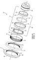
- Fig. 1 is an exploded isometric view of a prior art harmonic gear drive unit
- Fig. 2 is an axial cross section of a prior art harmonic gear drive unit
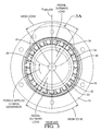
- Fig. 3 is a radial cross section of the harmonic gear drive unit of Fig. 2 taken through section line 3-3;
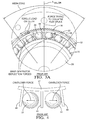
- Fig. 3A is an enlarged view of a portion of Fig. 3 ;
- Fig. 4 is a pair of adjacent balls in a ball cage of the harmonic gear drive unit of Fig. 1 ;
- Fig. 5 is an exploded isometric view of an eVCP in accordance with the present invention.
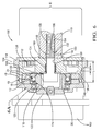
- Fig. 6 is an axial cross-section of an eVCP in accordance with the present invention.
- Fig. 6A is an enlarged view of circle 6A of Fig. 6 ;
- Fig. 7 is an isometric view of a sprocket housing of Fig. 5 .
- eVCP 100 in accordance with the present invention comprises flat harmonic gear drive unit 10; rotational actuator 102 that may be a hydraulic motor but is preferably a DC electric motor, operationally connected to harmonic gear drive unit 10; input sprocket 104 operationally connected to harmonic gear drive unit 10 and drivable in a fixed ratio by a crankshaft (not shown) of internal combustion engine 106; output hub 108 attached to harmonic gear drive unit 10 and mountable to an end of internal combustion engine camshaft 110; and bias spring 112 operationally disposed between output hub 108 and input sprocket 104.
- Electric motor 102 may be an axial-flux DC motor.
- Harmonic gear drive unit 10 includes the same elements and operates in the same way as described earlier.
- input sprocket 104 is rotationally fixed to a generally cup-shaped sprocket housing 114 that is fastened by bolts 116 to circular spline 12.
- Coupling adaptor 118 is mounted to wave generator 26 and extends through sprocket housing 114, being supported by bearing 120 mounted in sprocket housing 114. While coupling adapter 118 is shown to be made of unitary construction with wave generator 26, it should be understand that coupling adapter 118 may be made separately and joined to wave generator 26 by known joining methods.
- Coupling 122 mounted to the motor shaft of electric motor 102 and pinned thereto by pin 124 engages coupling adaptor 118, permitting wave generator 26 to be rotationally driven by electric motor 102, as may be desired to alter the phase relationship between circular spline 12 and dynamic spline 14.
- Output hub 108 is fastened to dynamic spline 14 by bolts 126 and may be secured to camshaft 110 by camshaft phaser attachment bolt 128 extending through output hub axial bore 130 in output hub 108, and capturing washer 132 and filter 134 recessed in output hub 108.
- radial run-out is limited by a single journal bearing interface defining journal bearing 136 between sprocket housing 114 (input hub) and output hub 108, thereby reducing the overall axial length of eVCP 100 and its cost to manufacture.
- Backplate 138 is press fit within sprocket housing 114 in order to retain output hub 108 within sprocket housing 114.
- Backplate 138 may also be retained by a retaining ring (not shown) fitted in a groove (also not shown) formed in the inner circumference of sprocket housing 114).
- Backplate 138 also captures bias spring 112 against output hub 108.
- Inner spring tang 140 of bias spring 112 is engaged by output hub 108, and outer spring tang 142 of bias spring 112 is attached to backplate 138 by pin 144.
- bias spring 112 is biased to back-drive harmonic gear drive unit 10 without help from electric motor 102 to a rotational position of dynamic spline 14 wherein internal combustion engine 106 will start or run, which position may be at one of the extreme ends of the range of authority or intermediate of the camshaft phaser's extreme ends of its rotational range of authority.
- the rotational range of travel in which bias spring 112 biases harmonic gear drive unit 10 may be limited to something short of the end stop position of the phaser's range of authority. Such an arrangement would be useful for internal combustion engines requiring an intermediate park position for idle or restart.
- the nominal diameter of output hub 108 is D; the nominal axial length of journal bearing 136 is L; and the nominal axial length of oil groove 146 formed in either output hub 108 (shown) and/or in sprocket housing 114 (not shown) for supplying oil to journal bearing 136 is W.
- the length L of journal bearing 136 in relation to output hub diameter D controls how much output hub 108 can tip within sprocket housing 114.
- the width of oil groove 146 in relation to journal bearing length L controls how much bearing contact area is available to carry the radial load.
- a currently preferred range of the ratio L/D may be between about 0.25 and about 0.40, and that a currently preferred range of the ratio W/L may be between about 0.15 and about 0.70.
- annular camshaft oil groove 148 supplied with oil by an oil gallery (not shown) of a camshaft bearing (also not shown).
- Annular camshaft oil groove 148 provides oil to camshaft oil passage 150 which extends radially through camshaft 110 from annular camshaft oil groove 148 to camshaft bore 152 of camshaft 110.
- Camshaft bore 152 includes small diameter portion 154 which threadably engages camshaft phaser attachment bolt 128.
- Camshaft bore 152 also includes large diameter portion 156 which defines camshaft annular space 158 with camshaft phaser attachment bolt 128 that is adjacent to output hub 108.
- Camshaft annular space 158 receives the oil from camshaft oil passage 150.
- Camshaft annular space 158 is in fluid communication with output hub annular space 160 which is defined between output hub axial bore 130 and camshaft phaser attachment bolt 128.
- the oil passes through filter 134 to prevent contaminants from passing further into eVCP 100.
- Filter 134 is a band-type filter that may be a screen or mesh and may be made from any number of different materials that are known in the art of oil filtering. After passing through filter 134, the oil is communicated to journal bearing oil passages 162 which extend radially through output hub 108 from output hub axial bore 130 to oil groove 146 for lubricating journal bearing 136.
- Oil may also be used to lubricate harmonic gear drive unit 10 and bearing 120.
- harmonic drive oil passage 164 is provided axially through output hub 108 beginning at one of the journal bearing oil passages 162 and extending toward harmonic gear drive unit 10 substantially parallel to the axis of rotation of eVCP 100. In this way, oil from journal bearing oil passage 162 is communicated to harmonic gear drive unit 10 and bearing 120.
- eVCP 100 is provided with a means for limiting the phase authority of eVCP 100.
- Sprocket housing 114 is provided with first and second arcuate input stop members 166, 168 which extend axially away from the bottom of sprocket housing 114.
- Output hub 108 includes corresponding features which interact with first and second arcuate input stop members 166, 168 to limit the phase authority of eVCP 100.
- Output hub 108 is provided with first and second arcuate output stop members 170, 172 which extend axially away from the surface of output hub 108 facing toward the bottom of sprocket housing 114 and which fit between first and second arcuate input stop members 166, 168 with clearance equal to the phase authority of eVCP 100.
- First and second arcuate input stop members 166, 168 are brought into contact with first and second arcuate output stop members 170, 172 respectively when eVCP 100 is positioned in one of a maximum advance position and a maximum retard position.
- first and second arcuate input stop members 166, 168 are brought into contact with second and first arcuate output stop members 172, 170 respectively when eVCP 100 is positioned in the other of the maximum advance position and the maximum retard position. In this way, the phase authority of eVCP 100 is mechanically limited.
- eVCP 100 is provided with support ring 174 which radially surrounds coupling 118.
- Support ring 174 is a rigid ring which includes retention portion 176 which is captured between coupling adapter flange 178 and bearing 120.
- Coupling adapter flange 178 extends radially outward from coupling adapter 118 to axially position wave generator bearing 28 on wave generator 26 and to axially position bearing 120 on coupling adapter 118.
- Wave generator bearing 28 is positioned on wave generator 26 such that inner race axial end 180 of inner race 30 is closely axially adjacent coupling adapter flange 178. Wave generator bearing 28 is retained on wave generator 26 by retaining ring 182 which fits within retaining ring groove 184 formed in wave generator 26. Wave generator bearing 28 is oriented on wave generator 26 such that annular section 42 is facing toward bearing 120. Bearing 120 is positioned on coupling adapter 118 by press fit until retention portion 176 is tightly captured between coupling adapter flange 178 and bearing 120.
- Support ring 174 also includes backup portion 186 which extends axially away from retention portion 176 toward wave generator bearing 28.
- Backup portion 186 extends axially beyond inner race axial end 180 toward annular section 42.
- Axial space 188 is preferably defined between backup portion 186 and annular section 42 to prevent friction between backup portion 186 and annular section 42.
- the rigid nature of support ring 174 and the close proximity of backup portion 186 to annular section 42 by extending axially beyond inner race axial end 180 toward annular section 42 provides support to annular section 42 when eVCP 100 has reached maximum phase authority in either the advance direction of phasing or the retard direction of phasing.
- This support of annular section 42 helps to keep ball cage 36 positioned axially correctly to minimize deflection of ball separators 44, provides additional stiffness to annular section 42, and minimizes axial misalignment of balls 34 which reduces cantilever forces on ball separators 44 which mitigate the wind-up effect on flexspline 16.
- harmonic gear drive unit 10 as comprising circular spline 12 which serves as the input member; dynamic spline 14 which serves as the output member and is coaxially positioned adjacent circular spline 12; flexspline 16 disposed radially inwards of both circular spline 12 and dynamic spline 14 and having outwardly-extending flexspline teeth 18 for engaging inwardly-extending circular spline teeth 20 and dynamic spline teeth 22; and wave generator assembly 24 disposed radially inwards of and engaging flexspline 16.
- harmonic gear drive unit 10 is a flat plate or pancake type harmonic gear drive unit as referred to in the art.
- a cup type harmonic gear drive unit may be used.
- the cup type harmonic gear drive unit comprises a circular spline which serves as the input member; a flexspline which serves as the output member and which is disposed radially inwards of the circular spline and having outwardly-extending gear teeth disposed for engaging inwardly-extending gear teeth on the circular spline; and a wave generator disposed radially inwards of and engaging the flexspline.
Landscapes
- Engineering & Computer Science (AREA)
- General Engineering & Computer Science (AREA)
- Mechanical Engineering (AREA)
- Valve Device For Special Equipments (AREA)
- Retarders (AREA)
Abstract
Description
- The present invention relates to an electric variable camshaft phaser (eVCP) which uses an electric motor and a harmonic gear drive unit to vary the phase relationship between a crankshaft and a camshaft in an internal combustion engine; more particularly, to an eVCP with a support ring to prevent deflection of a ball cage of the harmonic gear drive unit, and more particularly to such a support ring which extends axially into an inner race of the harmonic gear drive unit.
- Camshaft phasers for varying the timing of combustion valves in internal combustion engines are well known. A first element, known generally as a sprocket element, is driven by a chain, belt, or gearing from an engine's crankshaft. A second element, known generally as a camshaft plate, is mounted to the end of the engine's camshaft. A common type of camshaft phaser used by motor vehicle manufactures is known as a vane-type camshaft phaser.
US Patent No. 7,421,989 shows a typical vane-type camshaft phaser which generally comprises a plurality of outwardly-extending vanes on a rotor interspersed with a plurality of inwardly-extending lobes on a stator, forming alternating advance and retard chambers between the vanes and lobes. Engine oil is supplied via a multiport oil control valve, in accordance with an engine control module, to either the advance or retard chambers, to change the angular position of the rotor relative to the stator, as required to meet current or anticipated engine operating conditions. - While vane-type camshaft phasers are effective and relatively inexpensive, they do suffer from drawbacks. First, at low engine speeds, oil pressure tends to be low, and sometimes unacceptable. Therefore, the response of a vane-type camshaft phaser may be slow at low engine speeds. Second, at low environmental temperatures, and especially at engine start-up, engine oil displays a relatively high viscosity and is more difficult to pump, therefore making it more difficult to quickly supply engine oil to the vane-type camshaft phaser. Third, using engine oil to drive the vane-type camshaft phaser is parasitic on the engine oil system and can lead to requirement of a larger oil pump. Fourth, for fast actuation, a larger engine oil pump may be necessary, resulting in additional fuel consumption by the engine. Lastly, the total amount of phase authority provided by vane-type camshaft phasers is limited by the amount of space between adjacent vanes and lobes. A greater amount of phase authority may be desired than is capable of being provided between adjacent vanes and lobes. For at least these reasons, the automotive industry is developing electrically driven camshaft phasers.
- Harmonic gear drive units for angular positioning are also well known. Referring to
Figs. 1-2 , a typical flat plate harmonic gear drive unit is shown as harmonicgear drive unit 10. Harmonicgear drive unit 10 comprises outerfirst spline 12 which may be either a circular spline or a dynamic spline (hereinafter referred to as circular spline 12) as described below; outer second spline 14 (hereinafter referred to as dynamic spline 14) which is the opposite (dynamic or circular) ofcircular spline 12 and is coaxially positioned adjacentcircular spline 12;flexspline 16 disposed radially inwards of bothcircular spline 12 anddynamic spline 14 and having outwardly-extendingflexspline teeth 18 for engaging inwardly-extendingcircular spline teeth 20 ofcircular spline 12 and also for engaging inwardly-extendingdynamic spline teeth 22 ofdynamic spline 14; andwave generator assembly 24 disposed radially inwards of andengaging flexspline 16. -
Wave generator assembly 24 includes an ellipticalshaped wave generator 26 with wave generator bearing 28 fitted tightly overwave generator 26 to conform to the elliptically shaped circumference ofwave generator 26. Wave generator bearing 28 includesinner race 30,outer race 32, a plurality ofballs 34, andball cage 36.Inner race 30 is disposed immediately radially outward ofwave generator 26.Outer race 32 is disposed radially outward ofinner race 30 with the plurality ofballs 34 disposed radially betweeninner race 30 andouter race 32.Balls 34 ride withininner race groove 38 formed in the outer circumference ofinner race 30.Balls 34 also ride withinouter race groove 40 formed in the inner circumference ofouter race 32.Ball cage 36 includesannular section 42 from which a plurality ofball separators 44 extend axially such thatadjacent balls 34 are separated by one of the plurality ofball separators 44.Ball separators 44 includearcuate surfaces 46 which are concave and face toward anadjacent ball separator 44 to follow the contour ofballs 34.Arcuate surfaces 46 are concave such that the radius of eacharcuate surface 46 is in a plane substantially parallel toannular section 42. - Flexspline 16 is a non-rigid ring which is fitted tightly over and elastically deflected by
wave generator assembly 24. Flexsplineteeth 18 have a slightly smaller pitch diameter thancircular spline teeth 20. -
Circular spline 12 is a rigid ring withcircular spline teeth 20engaging flexspline teeth 18.Circular spline 12 has slightly fewercircular spline teeth 20 thanflexspline 16 hasflexspline teeth 18.Circular spline 12 serves as the input member. -
Dynamic spline 14 is a rigid ring withdynamic spline teeth 22engaging flexspline teeth 18.Dynamic spline 14 has the same number ofdynamic spline teeth 22 as flexspline 16 hasflexspline teeth 18.Dynamic spline 14 rotates together withflexspline 16 in a one-to-one relationship and serves as the output member. Of course, the circular spline may have more teeth than the dynamic spline, in which case the rotational relationship is then reversed. -
Dynamic spline 14 may be distinguished fromcircular spline 12 by chamferedcorners 48 at its outside diameter. Chamferedcorners 48 provide for visual distinction ofcircular spline 12 anddynamic spline 14 which may otherwise differ visually only by the number ofcircular spline teeth 20 anddynamic spline teeth 22 which may be difficult to visually discern. Alternatively, but not shown,dynamic spline 14 may not includechamfered corners 48, but rathercircular spline 12 may included chamfered corners at its outside diameter. - Now referring to
Figs. 1 ,2 ,3 ,3A, and 4 ,the elliptical shape ofwave generator assembly 24 causesflexspline teeth 18 to engage bothcircular spline teeth 20 anddynamic spline teeth 22 along and near major elliptical axis Amajor in twomesh zones 180° apart and symmetrical to major elliptical axis Amajor as shown inFigs. 3 and3A . Whenwave generator 26 is rotated relative tocircular spline 12 anddynamic spline 14, a rotation wave is generated in flexspline 16 (actually twowaves 180° apart, corresponding to opposite ends of the major ellipse axis Amajor). Sincedynamic spline 14 has the same number ofdynamic spline teeth 22 asflexspline 16 hasflexspline teeth 18, there is no relative rotation offlexspline 16 withdynamic spline 14. However, sincecircular spline 12 has slightly fewercircular spline teeth 20 thanflexspline 16 hasflexspline teeth 18,flexspline 16 rotates relative tocircular spline 12. As a result,circular spline 12 rotates past thedynamic spline 14 during rotation ofwave generator 26 relative todynamic spline 14, defining a gear ratio therebetween (for example, a gear ratio of 50:1 would mean that 1 rotation ofcircular spline 12 pastdynamic spline 14 corresponds to 50 rotations ofwave generator 26 relative to dynamic spline 14). Harmonicgear drive unit 10 is thus a high-ratio gear transmission; that is, the angular phase relationship betweencircular spline 12 anddynamic spline 14 changes by 2% for every revolution ofwave generator 26. - One type of electrically driven camshaft phaser being developed is shown in
US Patent Application Serial No. 12/536,575 ;US Patent Application Serial No. 12/844,918 ;US Patent Application Serial No. 12/825,806 ;US Patent Application Serial No. 12/848,599 ;US Patent Application Serial No. 12/965,057 ;US Patent Application Serial No. 13/102138 ;US Patent Application Serial No. 13/112,199 ;US Patent Application Serial No. 13/155,685 ; andUS Patent Application Serial No. 13/184,975 which are commonly owned by Applicant and incorporated herein by reference in their entirety. This electrically driven camshaft phaser utilizes a harmonic gear drive unit to change the phase relationship between the crankshaft and a camshaft of the internal combustion engine. This is accomplished by connecting the crankshaft to the circular spline of the harmonic gear drive unit in a fixed ratio of rotation and by connecting the camshaft to the dynamic spline of the harmonic gear drive unit in a fixed ratio or rotation. In this way, when the wave generator of the harmonic gear drive unit of the wave generator is rotated relative to the circular spline and dynamic spline, relative rotation between the circular spline and dynamic spline is generated, thereby resulting in a change of phase relationship between the crankshaft and the camshaft. - Typical angular positioning applications of harmonic gear drive units are not constrained to limit the angular positioning range. However, when a harmonic gear drive unit is used in a camshaft phaser to change the phase relationship between the crankshaft and the camshaft, stop members may be employed to limit the phase authority in order to prevent over-advancing and over-retarding which may, for example, result in undesired engine operation and engine damage due to interference of the engine valves and pistons. An example of such stop members is shown in
US Patent Application No. 12/844,918 - Referring now to
Figs. 3 ,3A, and 4 in whichcircular spline 12 is not visible and which represents a condition when the stop members (not shown) are engaged,circular spline 12 and thedynamic spline 14 of harmonicgear drive unit 10 are effectively locked relative to each other.Flexspline teeth 18, as always, maintain the two mesh zones withcircular spline teeth 20 anddynamic spline teeth 22 symmetrical about major elliptical axis Amajor. As torque is continued to be applied towave generator 26,flexspline 16 wants to continue drivingcircular spline 12 and thedynamic spline 14 in opposite directions, but cannot becausecircular spline 12 and thedynamic spline 14 are locked and thereforeflexspline 16 is also rotationally locked. The torque onwave generator 26 is resolved into both a torque load throughflexspline teeth 18,circular spline teeth 20, anddynamic spline teeth 22 in the two zones of mesh and also in a radial outward load wherewave generator 26 is trying to deflectflexspline 16 radially outward whereflexspline teeth 18 do not mesh withcircular spline teeth 20 and thedynamic spline teeth 22. The torque load betweenflexspline teeth 18 engaged withcircular spline teeth 20 and thedynamic spline teeth 22 resolves into a tangential force vector and a radial force vector, the radial force vector acting to pushflexspline 16 away fromcircular spline teeth 20 anddynamic spline teeth 22 radially. This radial force tries to collapseflexspline 16 in the mesh zone. These two forces acting onflexspline 16 try to collapseflexspline 16 inward at the center of the mesh zone (at Amajor). Inward collapse offlexspline 16 is resisted byballs 34. If one of theballs 34 was perfectly in the center of the mesh zone,flexspline 16 would not be able to deflect. However, the natural orientation ofballs 34 is to have one equal distance on each side of the center of the mesh zone. These forces are illustrated inFigs. 3 and3A . Under this condition, there are tangential force vectors which act to push eachball 34 adjacent each side of the center of the mesh zone apart as shown inFig. 4 which shows annular section being deformed in an arched shape from its normally straight shape.Ball separators 44 preventballs 34 from moving a significant amount, however,balls 34 apply a cantilever load onball separators 44, causingball cage 36 to move axially. Axial misalignment ofballs 34 as a result of these conditions may increase the cantilever load onball separators 44. Asball cage 36 moves axially, the cantilever load onball separators 44 increases, causingannular section 42 to deform. It is this deformation ofannular section 42 that allows wind-up offlexspline 16. This wind-up may lead to durability and operational issues of harmonicgear drive unit 10. -
US Patent No. 3,285,099 shows an example of a wave generator bearing for a harmonic gear drive unit. In this example, a portion of the wave generator extends radially outward. When the inner race is placed on the wave generator, an inner race axial end of the inner race is positioned against the portion of the wave generator that extends radially outward. An annular section of a ball cage is placed proximal to and axially inward of the inner race axial end, defining an axial space between the annular section and the portion of the wage generator extending radially outward. Since the portion of the wave generator that extends radially outward is flush with the inner race axial end, it may not provide sufficient axial support to the ball cage. - What is needed is an eVCP which minimizes deformation of a ball cage of a harmonic gear drive unit and which minimizes wind-up of a flexspline of a harmonic gear drive unit.
- Briefly described, a camshaft phaser for controllably varying the phase relationship between a crankshaft and a camshaft in an internal combustion engine is provided. The camshaft phaser includes a housing having a longitudinal axis with a harmonic gear drive unit disposed therewithin. The harmonic gear drive unit includes a circular spline and an axially adj acent dynamic spline, a flexspline disposed within the circular spline and the dynamic spline, a wave generator assembly disposed within the flexspline, and a rotational actuator connectable to the wave generator assembly such that rotation of the wave generator assembly causes relative rotation between the circular spline and the dynamic spline. The wave generator assembly includes an elliptical wave generator surrounded tightly with an inner race having an inner race axial end, an outer race surrounded tightly with the flexspline, a plurality of balls disposed between the inner race and the outer race, and a ball cage having an annular section disposed axial from the balls proximal to the inner race axial end and a plurality of ball separators extending axially from the annular section such that consecutive balls are separated by one of the ball separators. One of the circular spline and the dynamic spline is fixed to the housing in order to prevent relative rotation therebetween. A hub is rotatably disposed within the housing axially adjacent to the harmonic gear drive unit and attachable to the camshaft and fixed to the other of the circular spline and the dynamic spline in order to prevent relative rotation therebetween. A rigid support ring is fixed axially with the housing and extends axially beyond the inner race axial end toward the annular section to limit axial distortion of the annular section.
- This invention will be further described with reference to the accompanying drawings in which:
-
Fig. 1 is an exploded isometric view of a prior art harmonic gear drive unit; -
Fig. 2 is an axial cross section of a prior art harmonic gear drive unit; -
Fig. 3 is a radial cross section of the harmonic gear drive unit ofFig. 2 taken through section line 3-3; -
Fig. 3A is an enlarged view of a portion ofFig. 3 ; -
Fig. 4 is a pair of adjacent balls in a ball cage of the harmonic gear drive unit ofFig. 1 ; -
Fig. 5 is an exploded isometric view of an eVCP in accordance with the present invention; -
Fig. 6 is an axial cross-section of an eVCP in accordance with the present invention; -
Fig. 6A is an enlarged view ofcircle 6A ofFig. 6 ; and -
Fig. 7 is an isometric view of a sprocket housing ofFig. 5 . - Referring to
FIGS. 5 and6 ,eVCP 100 in accordance with the present invention comprises flat harmonicgear drive unit 10;rotational actuator 102 that may be a hydraulic motor but is preferably a DC electric motor, operationally connected to harmonicgear drive unit 10;input sprocket 104 operationally connected to harmonicgear drive unit 10 and drivable in a fixed ratio by a crankshaft (not shown) ofinternal combustion engine 106;output hub 108 attached to harmonicgear drive unit 10 and mountable to an end of internalcombustion engine camshaft 110; andbias spring 112 operationally disposed betweenoutput hub 108 andinput sprocket 104.Electric motor 102 may be an axial-flux DC motor. Harmonicgear drive unit 10 includes the same elements and operates in the same way as described earlier. - Still referring to
FIGS. 5 and6 ,input sprocket 104 is rotationally fixed to a generally cup-shapedsprocket housing 114 that is fastened bybolts 116 tocircular spline 12.Coupling adaptor 118 is mounted to wavegenerator 26 and extends throughsprocket housing 114, being supported by bearing 120 mounted insprocket housing 114. Whilecoupling adapter 118 is shown to be made of unitary construction withwave generator 26, it should be understand thatcoupling adapter 118 may be made separately and joined to wavegenerator 26 by known joining methods. Coupling 122 mounted to the motor shaft ofelectric motor 102 and pinned thereto bypin 124 engagescoupling adaptor 118, permittingwave generator 26 to be rotationally driven byelectric motor 102, as may be desired to alter the phase relationship betweencircular spline 12 anddynamic spline 14. -
Output hub 108 is fastened todynamic spline 14 bybolts 126 and may be secured tocamshaft 110 by camshaftphaser attachment bolt 128 extending through output hubaxial bore 130 inoutput hub 108, and capturingwasher 132 and filter 134 recessed inoutput hub 108. - In an eVCP, it is necessary to limit radial run-out between the input hub and output hub. Referring to
FIG. 6 , radial run-out is limited by a single journal bearing interface defining journal bearing 136 between sprocket housing 114 (input hub) andoutput hub 108, thereby reducing the overall axial length ofeVCP 100 and its cost to manufacture. -
Backplate 138 is press fit withinsprocket housing 114 in order to retainoutput hub 108 withinsprocket housing 114.Backplate 138 may also be retained by a retaining ring (not shown) fitted in a groove (also not shown) formed in the inner circumference of sprocket housing 114).Backplate 138 also capturesbias spring 112 againstoutput hub 108.Inner spring tang 140 ofbias spring 112 is engaged byoutput hub 108, andouter spring tang 142 ofbias spring 112 is attached tobackplate 138 bypin 144. In the event of an electric motor malfunction,bias spring 112 is biased to back-drive harmonicgear drive unit 10 without help fromelectric motor 102 to a rotational position ofdynamic spline 14 whereininternal combustion engine 106 will start or run, which position may be at one of the extreme ends of the range of authority or intermediate of the camshaft phaser's extreme ends of its rotational range of authority. For example, the rotational range of travel in which biasspring 112 biases harmonicgear drive unit 10 may be limited to something short of the end stop position of the phaser's range of authority. Such an arrangement would be useful for internal combustion engines requiring an intermediate park position for idle or restart. - The nominal diameter of
output hub 108 is D; the nominal axial length of journal bearing 136 is L; and the nominal axial length ofoil groove 146 formed in either output hub 108 (shown) and/or in sprocket housing 114 (not shown) for supplying oil to journal bearing 136 is W. In addition to journal bearing clearance, the length L of journal bearing 136 in relation to output hub diameter D controls howmuch output hub 108 can tip withinsprocket housing 114. The width ofoil groove 146 in relation to journal bearing length L controls how much bearing contact area is available to carry the radial load. Experimentation has shown that a currently preferred range of the ratio L/D may be between about 0.25 and about 0.40, and that a currently preferred range of the ratio W/L may be between about 0.15 and about 0.70. - In order to lubricate various elements of
eVCP 100, oil is provided thereto frominternal combustion engine 106 through annularcamshaft oil groove 148 supplied with oil by an oil gallery (not shown) of a camshaft bearing (also not shown). Annularcamshaft oil groove 148 provides oil tocamshaft oil passage 150 which extends radially throughcamshaft 110 from annularcamshaft oil groove 148 to camshaft bore 152 ofcamshaft 110. Camshaft bore 152 includessmall diameter portion 154 which threadably engages camshaftphaser attachment bolt 128. Camshaft bore 152 also includeslarge diameter portion 156 which defines camshaftannular space 158 with camshaftphaser attachment bolt 128 that is adjacent tooutput hub 108. Camshaftannular space 158 receives the oil fromcamshaft oil passage 150. Camshaftannular space 158 is in fluid communication with output hubannular space 160 which is defined between output hubaxial bore 130 and camshaftphaser attachment bolt 128. From output hubannular space 160, the oil passes throughfilter 134 to prevent contaminants from passing further intoeVCP 100.Filter 134 is a band-type filter that may be a screen or mesh and may be made from any number of different materials that are known in the art of oil filtering. After passing throughfilter 134, the oil is communicated to journal bearingoil passages 162 which extend radially throughoutput hub 108 from output hub axial bore 130 tooil groove 146 for lubricating journal bearing 136. - Oil may also be used to lubricate harmonic
gear drive unit 10 andbearing 120. In order to supply oil thereto, harmonicdrive oil passage 164 is provided axially throughoutput hub 108 beginning at one of the journal bearingoil passages 162 and extending toward harmonicgear drive unit 10 substantially parallel to the axis of rotation ofeVCP 100. In this way, oil from journal bearingoil passage 162 is communicated to harmonicgear drive unit 10 andbearing 120. - Now referring to
Figs. 5 and7 ,eVCP 100 is provided with a means for limiting the phase authority ofeVCP 100.Sprocket housing 114 is provided with first and second arcuateinput stop members sprocket housing 114.Output hub 108 includes corresponding features which interact with first and second arcuateinput stop members eVCP 100.Output hub 108 is provided with first and second arcuateoutput stop members output hub 108 facing toward the bottom ofsprocket housing 114 and which fit between first and second arcuateinput stop members eVCP 100. First and second arcuateinput stop members output stop members eVCP 100 is positioned in one of a maximum advance position and a maximum retard position. Similarly, first and second arcuateinput stop members output stop members eVCP 100 is positioned in the other of the maximum advance position and the maximum retard position. In this way, the phase authority ofeVCP 100 is mechanically limited. - In order to minimize the undesired wind-up of
flexspline 16 resulting from distortion ofannular section 42 ofball cage 36 and referring toFigs. 5 ,6 , and6A ,eVCP 100 is provided withsupport ring 174 which radially surroundscoupling 118.Support ring 174 is a rigid ring which includesretention portion 176 which is captured betweencoupling adapter flange 178 andbearing 120. Couplingadapter flange 178 extends radially outward fromcoupling adapter 118 to axially position wave generator bearing 28 onwave generator 26 and to axially position bearing 120 oncoupling adapter 118. Wave generator bearing 28 is positioned onwave generator 26 such that inner raceaxial end 180 ofinner race 30 is closely axially adjacentcoupling adapter flange 178. Wave generator bearing 28 is retained onwave generator 26 by retainingring 182 which fits within retainingring groove 184 formed inwave generator 26. Wave generator bearing 28 is oriented onwave generator 26 such thatannular section 42 is facing towardbearing 120. Bearing 120 is positioned oncoupling adapter 118 by press fit untilretention portion 176 is tightly captured betweencoupling adapter flange 178 andbearing 120. -
Support ring 174 also includesbackup portion 186 which extends axially away fromretention portion 176 towardwave generator bearing 28.Backup portion 186 extends axially beyond inner raceaxial end 180 towardannular section 42.Axial space 188 is preferably defined betweenbackup portion 186 andannular section 42 to prevent friction betweenbackup portion 186 andannular section 42. The rigid nature ofsupport ring 174 and the close proximity ofbackup portion 186 toannular section 42 by extending axially beyond inner raceaxial end 180 towardannular section 42 provides support toannular section 42 wheneVCP 100 has reached maximum phase authority in either the advance direction of phasing or the retard direction of phasing. This support ofannular section 42 helps to keepball cage 36 positioned axially correctly to minimize deflection ofball separators 44, provides additional stiffness toannular section 42, and minimizes axial misalignment ofballs 34 which reduces cantilever forces onball separators 44 which mitigate the wind-up effect onflexspline 16. - The embodiment described herein describes harmonic
gear drive unit 10 as comprisingcircular spline 12 which serves as the input member;dynamic spline 14 which serves as the output member and is coaxially positioned adjacentcircular spline 12;flexspline 16 disposed radially inwards of bothcircular spline 12 anddynamic spline 14 and having outwardly-extendingflexspline teeth 18 for engaging inwardly-extendingcircular spline teeth 20 anddynamic spline teeth 22; andwave generator assembly 24 disposed radially inwards of and engagingflexspline 16. As described, harmonicgear drive unit 10 is a flat plate or pancake type harmonic gear drive unit as referred to in the art. However, it should now be understood that other types of harmonic gear drive units may be used in accordance with the present invention. For example, a cup type harmonic gear drive unit may be used. The cup type harmonic gear drive unit comprises a circular spline which serves as the input member; a flexspline which serves as the output member and which is disposed radially inwards of the circular spline and having outwardly-extending gear teeth disposed for engaging inwardly-extending gear teeth on the circular spline; and a wave generator disposed radially inwards of and engaging the flexspline. - While this invention has been described in terms of preferred embodiments thereof, it is not intended to be so limited, but rather only to the extent set forth in the claims that follow.
Claims (6)
- A camshaft phaser (100) for controllably varying the phase relationship between a crankshaft and a camshaft in an internal combustion engine (106), said camshaft phaser (100) comprising:a harmonic gear drive unit (10) including an input member (12), an output member (14), a wave generator assembly (26) disposed within said input member (12) and said output member (14), and a rotational actuator (102) connectable to said wave generator assembly (26) such that rotation of said wave generator assembly (26) causes relative rotation between said input member (12) and said output member (14), wherein said wave generator assembly (26) includes an elliptical wave generator surrounded tightly with an inner race (30) having an inner race axial end (180), an outer race (32), a plurality of balls (34) disposed between said inner race (30) and said outer race (32), and a ball cage (36) having an annular section disposed axial from said balls (34) proximal to said inner race axial end (180) and a plurality of ball separators (44) extending axially from said annular section such that consecutive balls (34) are separated by one of said ball separators (44); anda rigid support ring (174) fixed axially and extending axially beyond said inner race axial end (180) toward said annular section (42) to limit axial deflection of said annular section (42).
- A camshaft phaser (100) as in claim 1 further comprising a housing (114) having a longitudinal axis, said harmonic gear drive unit (10) being disposed within said housing (114);
wherein said gear drive unit (10) comprises a circular spline (12) and an axially adjacent dynamic spline (14), a flexspline (16) disposed within said circular spline (12) and said dynamic spline (14), said wave generator assembly (26) being disposed within said flexspline (16);
wherein said outer race (32) is surrounded tightly with said flexspline (16);
wherein one of said circular spline (12) and said dynamic spline (14) is fixed to said housing (114) in order to prevent relative rotation therebetween; and
wherein a hub (108) is rotatably disposed within said housing (114) axially adjacent to said harmonic gear drive unit (10) and attachable to said camshaft and fixed to the other of said circular spline (12) and said dynamic spline (14) in order to prevent relative rotation therebetween. - A camshaft phaser (100) as in claim 1 or 2 further comprising:a coupling adapter (118) mounted to said wave generator (26) and attachable to said rotational actuator (102), said coupling adapter (118) including a coupling adapter flange (178) extending radially outward therefrom; anda bearing (120) radially surrounding said coupling adapter (118);wherein a retention portion (176) of said support ring (174) is axially captured between said coupling adapter flange (178) and said bearing (120).
- A camshaft phaser (100) as in claim 3 wherein said support ring (174) includes a backup portion (186) extending axially from said retention portion (176) axially beyond said inner race axial end (180) toward said annular section (42).
- A camshaft phaser (100) as in claim 4 wherein an axial space (188) is defined between said backup portion (186) and said annular section (42).
- A camshaft phaser (100) as in any of the preceding claims further comprising stop members (166, 168, 170, 172) for limiting phase authority of said camshaft phaser (100).
Applications Claiming Priority (1)
| Application Number | Priority Date | Filing Date | Title |
|---|---|---|---|
| US13/249,286 US8516983B2 (en) | 2011-09-30 | 2011-09-30 | Harmonic drive camshaft phaser with a harmonic drive ring to prevent ball cage deflection |
Publications (2)
| Publication Number | Publication Date |
|---|---|
| EP2574745A1 true EP2574745A1 (en) | 2013-04-03 |
| EP2574745B1 EP2574745B1 (en) | 2015-04-22 |
Family
ID=46980787
Family Applications (1)
| Application Number | Title | Priority Date | Filing Date |
|---|---|---|---|
| EP20120185243 Not-in-force EP2574745B1 (en) | 2011-09-30 | 2012-09-20 | Harmonic drive camshaft phaser with a harmonic drive ring to prevent ball cage deflection. |
Country Status (2)
| Country | Link |
|---|---|
| US (1) | US8516983B2 (en) |
| EP (1) | EP2574745B1 (en) |
Cited By (14)
| Publication number | Priority date | Publication date | Assignee | Title |
|---|---|---|---|---|
| EP2905509A1 (en) * | 2013-08-01 | 2015-08-12 | Delphi Technologies, Inc. | Axially compact electrically driven camshaft phaser |
| EP2816203A3 (en) * | 2013-06-18 | 2015-08-26 | Delphi Technologies, Inc. | Camshaft phaser |
| TWI572796B (en) * | 2015-05-15 | 2017-03-01 | Harmonic gear differential gearbox | |
| EP3214344A1 (en) * | 2016-03-04 | 2017-09-06 | Ovalo GmbH | Wave generator for a harmonic drive |
| CN107709837A (en) * | 2015-04-15 | 2018-02-16 | 詹尼斯机器人技术有限公司 | Ripple actuator |
| CN108223560A (en) * | 2018-03-05 | 2018-06-29 | 西安施迈传动科技有限公司 | A kind of new harmonic bearing |
| EP3312475A3 (en) * | 2016-10-20 | 2018-09-12 | Hamilton Sundstrand Corporation | Compound harmonic drive assembly |
| CN109906310A (en) * | 2016-10-25 | 2019-06-18 | 舍弗勒技术股份两合公司 | Adjusting gear for a vehicle, vehicle having an adjusting gear, and method for assembling an adjusting gear |
| EP3537004A1 (en) * | 2018-03-08 | 2019-09-11 | Ovalo GmbH | Device for assembling radial flexible bearings on wave generators |
| EP3748201A3 (en) * | 2019-06-07 | 2021-04-07 | BeijingWest Industries Co. Ltd. | A compact belted strain wave gear apparatus |
| US20220112848A1 (en) * | 2020-10-12 | 2022-04-14 | Schaeffler Technologies AG & Co., KG | Actuation assembly for phaser system |
| US20220252015A1 (en) * | 2021-02-11 | 2022-08-11 | Schaeffler Technologies AG & Co. KG | Cranktrain phase adjuster for variable compression ratio |
| US11428173B2 (en) * | 2020-10-06 | 2022-08-30 | Schaeffler Technologies AG & Co. KG | Cranktrain phase adjuster for variable compression ratio |
| US12000470B2 (en) | 2019-06-07 | 2024-06-04 | Beijingwest Industries Co., Ltd | Compact belted strain wave gear apparatus and a vehicle lifting system including the compact belted strain wave gear apparatus |
Families Citing this family (17)
| Publication number | Priority date | Publication date | Assignee | Title |
|---|---|---|---|---|
| US8622037B2 (en) * | 2010-05-12 | 2014-01-07 | Delphi Technologies, Inc. | Harmonic drive camshaft phaser with a compact drive sprocket |
| US8800513B2 (en) * | 2011-05-20 | 2014-08-12 | Delphi Technologies, Inc. | Axially compact coupling for a camshaft phaser actuated by electric motor |
| US8677961B2 (en) * | 2011-07-18 | 2014-03-25 | Delphi Technologies, Inc. | Harmonic drive camshaft phaser with lock pin for selectivley preventing a change in phase relationship |
| TWM441059U (en) * | 2012-06-13 | 2012-11-11 | Harmonic Innovation Technology Co Ltd | Flexspline mounting structure of harmonic drive reducer |
| US8888374B1 (en) * | 2013-05-08 | 2014-11-18 | Hiwin Technologies Corp. | Bearing with antiskid design |
| CN104379966B (en) * | 2013-06-20 | 2017-03-08 | 谐波传动系统有限公司 | Wave gear device |
| US9145919B2 (en) | 2013-08-14 | 2015-09-29 | Mao-Tu Lee | Speed-reduction transmission bearing |
| EP2837849A1 (en) | 2013-08-16 | 2015-02-18 | Lee Mao-Tu | Wave gear mechanism |
| JP5924323B2 (en) * | 2013-09-18 | 2016-05-25 | 株式会社デンソー | Valve timing adjustment device |
| US9534513B2 (en) | 2014-01-16 | 2017-01-03 | Delphi Technologies, Inc. | Camshaft phaser actuated by an electric motor |
| JP6107693B2 (en) * | 2014-02-06 | 2017-04-05 | 株式会社デンソー | Valve timing adjustment device |
| US9664073B2 (en) | 2014-02-25 | 2017-05-30 | Delphi Technologies, Inc. | Modular electrically actuated camshaft phaser |
| US9151191B1 (en) | 2014-04-01 | 2015-10-06 | Delphi Technologies, Inc. | Electrically actuated camshaft phaser |
| WO2016044044A1 (en) * | 2014-09-17 | 2016-03-24 | Borgwarner Inc. | Engine variable camshaft timing phaser with planetary gear set |
| US9617878B2 (en) | 2015-02-04 | 2017-04-11 | Delphi Technologies, Inc. | Camshaft phaser and actuator for the same |
| DE102016216927A1 (en) | 2015-09-10 | 2017-03-16 | Schaeffler Technologies AG & Co. KG | Phaser |
| WO2019054185A1 (en) * | 2017-09-12 | 2019-03-21 | 日立オートモティブシステムズ株式会社 | Valve timing control device for internal combustion engine |
Citations (9)
| Publication number | Priority date | Publication date | Assignee | Title |
|---|---|---|---|---|
| US2038010A (en) * | 1934-11-20 | 1936-04-21 | Fed Bearings Co Inc | Ball bearing |
| US3285099A (en) | 1963-10-21 | 1966-11-15 | United Shoe Machinery Corp | Harmonic drive bearings |
| GB2168766A (en) * | 1984-12-22 | 1986-06-25 | Kugelfischer G Schaefer & Co | An anti-friction bearing |
| US4715247A (en) * | 1985-09-26 | 1987-12-29 | Kabushiki Kaisha Toshiba | Transmission apparatus with reduced frictional force |
| US5937710A (en) * | 1998-04-06 | 1999-08-17 | Teijin Seiki Boston, Inc | Harmonic-drive transmission |
| US7421989B2 (en) | 2005-09-13 | 2008-09-09 | Delphi Technologies, Inc. | Vane-type cam phaser having increased rotational authority, intermediate position locking, and dedicated oil supply |
| JP2009008170A (en) * | 2007-06-28 | 2009-01-15 | Nsk Ltd | Retainer made of resin, and ball bearing using this retainer |
| DE102008053913A1 (en) * | 2008-10-30 | 2010-05-12 | Ovalo Gmbh | Mounting arrangement for mounting shaft generator of harmonic drive transmission in e.g. vehicle steering system, has bearing for supporting generator and formed by circular and/or dynamic splines that perform transmission function |
| EP2282021A1 (en) * | 2009-08-06 | 2011-02-09 | Delphi Technologies, Inc. | Harmonic drive camshaft phaser with improved radial stability |
Family Cites Families (9)
| Publication number | Priority date | Publication date | Assignee | Title |
|---|---|---|---|---|
| US4451098A (en) | 1982-08-26 | 1984-05-29 | Usm Corporation | Ball separator assembly |
| US5417186A (en) | 1993-06-28 | 1995-05-23 | Clemson University | Dual-acting apparatus for variable valve timing and the like |
| US6302073B1 (en) * | 1999-03-23 | 2001-10-16 | Tcg Unitech Aktiengesellschaft | Device for adjusting the phase angle of a camshaft of an internal combustion engine |
| US6257186B1 (en) | 1999-03-23 | 2001-07-10 | Tcg Unitech Aktiengesellschaft | Device for adjusting the phase angle of a camshaft of an internal combustion engine |
| US6328006B1 (en) | 1999-03-23 | 2001-12-11 | Tcg Unitech Aktiengesellschaft | Device for adjusting the phase angle of a camshaft of an internal combustion engine |
| US7421990B2 (en) | 2006-08-22 | 2008-09-09 | Delphi Technologies, Inc. | Harmonic drive camshaft phaser |
| DE102007034091A1 (en) | 2007-07-21 | 2009-01-22 | Schaeffler Kg | Wave generator for a wave gear |
| US8584633B2 (en) | 2009-08-06 | 2013-11-19 | Delphi Technologies, Inc. | Harmonic drive camshaft phaser with bias spring |
| US8424500B2 (en) | 2009-08-06 | 2013-04-23 | Delphi Technologies, Inc. | Harmonic drive camshaft phaser with improved radial stability |
-
2011
- 2011-09-30 US US13/249,286 patent/US8516983B2/en active Active
-
2012
- 2012-09-20 EP EP20120185243 patent/EP2574745B1/en not_active Not-in-force
Patent Citations (9)
| Publication number | Priority date | Publication date | Assignee | Title |
|---|---|---|---|---|
| US2038010A (en) * | 1934-11-20 | 1936-04-21 | Fed Bearings Co Inc | Ball bearing |
| US3285099A (en) | 1963-10-21 | 1966-11-15 | United Shoe Machinery Corp | Harmonic drive bearings |
| GB2168766A (en) * | 1984-12-22 | 1986-06-25 | Kugelfischer G Schaefer & Co | An anti-friction bearing |
| US4715247A (en) * | 1985-09-26 | 1987-12-29 | Kabushiki Kaisha Toshiba | Transmission apparatus with reduced frictional force |
| US5937710A (en) * | 1998-04-06 | 1999-08-17 | Teijin Seiki Boston, Inc | Harmonic-drive transmission |
| US7421989B2 (en) | 2005-09-13 | 2008-09-09 | Delphi Technologies, Inc. | Vane-type cam phaser having increased rotational authority, intermediate position locking, and dedicated oil supply |
| JP2009008170A (en) * | 2007-06-28 | 2009-01-15 | Nsk Ltd | Retainer made of resin, and ball bearing using this retainer |
| DE102008053913A1 (en) * | 2008-10-30 | 2010-05-12 | Ovalo Gmbh | Mounting arrangement for mounting shaft generator of harmonic drive transmission in e.g. vehicle steering system, has bearing for supporting generator and formed by circular and/or dynamic splines that perform transmission function |
| EP2282021A1 (en) * | 2009-08-06 | 2011-02-09 | Delphi Technologies, Inc. | Harmonic drive camshaft phaser with improved radial stability |
Cited By (24)
| Publication number | Priority date | Publication date | Assignee | Title |
|---|---|---|---|---|
| EP2816203A3 (en) * | 2013-06-18 | 2015-08-26 | Delphi Technologies, Inc. | Camshaft phaser |
| EP2905509A1 (en) * | 2013-08-01 | 2015-08-12 | Delphi Technologies, Inc. | Axially compact electrically driven camshaft phaser |
| CN107709837A (en) * | 2015-04-15 | 2018-02-16 | 詹尼斯机器人技术有限公司 | Ripple actuator |
| CN107709837B (en) * | 2015-04-15 | 2022-04-29 | 詹尼斯机器人技术有限公司 | Wave actuator |
| TWI572796B (en) * | 2015-05-15 | 2017-03-01 | Harmonic gear differential gearbox | |
| CN107152455A (en) * | 2016-03-04 | 2017-09-12 | 奥维罗有限责任公司 | Shaft-type generators for stress wave transmission mechanism |
| LU92987B1 (en) * | 2016-03-04 | 2017-09-19 | Ovalo Gmbh | Wave generator for a stress wave transmission |
| EP3214344A1 (en) * | 2016-03-04 | 2017-09-06 | Ovalo GmbH | Wave generator for a harmonic drive |
| CN107152455B (en) * | 2016-03-04 | 2021-05-11 | 奥维罗有限责任公司 | Shaft type generator for stress wave transmission mechanism |
| EP3312475A3 (en) * | 2016-10-20 | 2018-09-12 | Hamilton Sundstrand Corporation | Compound harmonic drive assembly |
| US10400878B2 (en) | 2016-10-20 | 2019-09-03 | Hamilton Sundstrand Corporation | Compound harmonic drive assembly |
| CN109906310A (en) * | 2016-10-25 | 2019-06-18 | 舍弗勒技术股份两合公司 | Adjusting gear for a vehicle, vehicle having an adjusting gear, and method for assembling an adjusting gear |
| US11226028B2 (en) | 2016-10-25 | 2022-01-18 | Schaeffler Technologies AG & Co. KG | Variable-speed gear arrangement for a vehicle, vehicle comprising the variable-speed gear arrangement, and method for assembling the variable-speed gear arrangement |
| CN108223560A (en) * | 2018-03-05 | 2018-06-29 | 西安施迈传动科技有限公司 | A kind of new harmonic bearing |
| EP3537004A1 (en) * | 2018-03-08 | 2019-09-11 | Ovalo GmbH | Device for assembling radial flexible bearings on wave generators |
| DE202019005675U1 (en) | 2018-03-08 | 2021-06-02 | Ovalo Gmbh | Device for mounting radially flexible roller bearings on shaft generators |
| EP3748201A3 (en) * | 2019-06-07 | 2021-04-07 | BeijingWest Industries Co. Ltd. | A compact belted strain wave gear apparatus |
| US11384825B2 (en) | 2019-06-07 | 2022-07-12 | Beijingwest Industries Co., Ltd. | Compact belted strain wave gear apparatus and a vehicle lifting system including the compact belted strain wave gear apparatus |
| US12000470B2 (en) | 2019-06-07 | 2024-06-04 | Beijingwest Industries Co., Ltd | Compact belted strain wave gear apparatus and a vehicle lifting system including the compact belted strain wave gear apparatus |
| US11428173B2 (en) * | 2020-10-06 | 2022-08-30 | Schaeffler Technologies AG & Co. KG | Cranktrain phase adjuster for variable compression ratio |
| US20220112848A1 (en) * | 2020-10-12 | 2022-04-14 | Schaeffler Technologies AG & Co., KG | Actuation assembly for phaser system |
| US11619182B2 (en) * | 2020-10-12 | 2023-04-04 | Schaeffler Technologies AG & Co. KG | Actuation assembly for phaser system |
| US20220252015A1 (en) * | 2021-02-11 | 2022-08-11 | Schaeffler Technologies AG & Co. KG | Cranktrain phase adjuster for variable compression ratio |
| US11519342B2 (en) * | 2021-02-11 | 2022-12-06 | Schaeffler Technologies AG & Co. KG | Cranktrain phase adjuster for variable compression ratio |
Also Published As
| Publication number | Publication date |
|---|---|
| US20130081587A1 (en) | 2013-04-04 |
| EP2574745B1 (en) | 2015-04-22 |
| US8516983B2 (en) | 2013-08-27 |
Similar Documents
| Publication | Publication Date | Title |
|---|---|---|
| EP2574745B1 (en) | Harmonic drive camshaft phaser with a harmonic drive ring to prevent ball cage deflection. | |
| US8677961B2 (en) | Harmonic drive camshaft phaser with lock pin for selectivley preventing a change in phase relationship | |
| EP2905509B1 (en) | Axially compact electrically driven camshaft phaser | |
| US8555836B2 (en) | Electric drive camshaft phaser with torque rate limit at travel stops | |
| US9534513B2 (en) | Camshaft phaser actuated by an electric motor | |
| US8726865B2 (en) | Harmonic drive camshaft phaser using oil for lubrication | |
| US8322318B2 (en) | Harmonic drive camshaft phaser with phase authority stops | |
| EP2386732B1 (en) | Harmonic drive camshaft phaser with a compact drive sprocket | |
| EP2539556B1 (en) | Electrical camshaft phaser with energy recovery | |
| US8800513B2 (en) | Axially compact coupling for a camshaft phaser actuated by electric motor | |
| US8516982B2 (en) | Harmonic drive camshaft phaser and method for using | |
| EP2816203B1 (en) | Camshaft phaser | |
| EP2937529B1 (en) | Modular electrically actuated camshaft phaser | |
| EP2282020A1 (en) | Harmonic drive camshaft phaser with bias spring | |
| US20110030632A1 (en) | Harmonic Drive Camshaft Phaser with Improved Radial Stability | |
| EP2282021A1 (en) | Harmonic drive camshaft phaser with improved radial stability | |
| US9869214B2 (en) | Multi-positional camshaft phaser with two one-way wedge clutches and spring actuator | |
| CN116104880A (en) | Torque limiting rotor coupling for an electrically driven camshaft phaser |
Legal Events
| Date | Code | Title | Description |
|---|---|---|---|
| PUAI | Public reference made under article 153(3) epc to a published international application that has entered the european phase |
Free format text: ORIGINAL CODE: 0009012 |
|
| AK | Designated contracting states |
Kind code of ref document: A1 Designated state(s): AL AT BE BG CH CY CZ DE DK EE ES FI FR GB GR HR HU IE IS IT LI LT LU LV MC MK MT NL NO PL PT RO RS SE SI SK SM TR |
|
| AX | Request for extension of the european patent |
Extension state: BA ME |
|
| 17P | Request for examination filed |
Effective date: 20131004 |
|
| RBV | Designated contracting states (corrected) |
Designated state(s): AL AT BE BG CH CY CZ DE DK EE ES FI FR GB GR HR HU IE IS IT LI LT LU LV MC MK MT NL NO PL PT RO RS SE SI SK SM TR |
|
| 17Q | First examination report despatched |
Effective date: 20140526 |
|
| GRAP | Despatch of communication of intention to grant a patent |
Free format text: ORIGINAL CODE: EPIDOSNIGR1 |
|
| INTG | Intention to grant announced |
Effective date: 20141119 |
|
| GRAS | Grant fee paid |
Free format text: ORIGINAL CODE: EPIDOSNIGR3 |
|
| GRAA | (expected) grant |
Free format text: ORIGINAL CODE: 0009210 |
|
| AK | Designated contracting states |
Kind code of ref document: B1 Designated state(s): AL AT BE BG CH CY CZ DE DK EE ES FI FR GB GR HR HU IE IS IT LI LT LU LV MC MK MT NL NO PL PT RO RS SE SI SK SM TR |
|
| REG | Reference to a national code |
Ref country code: GB Ref legal event code: FG4D |
|
| REG | Reference to a national code |
Ref country code: CH Ref legal event code: EP |
|
| REG | Reference to a national code |
Ref country code: AT Ref legal event code: REF Ref document number: 723361 Country of ref document: AT Kind code of ref document: T Effective date: 20150515 |
|
| REG | Reference to a national code |
Ref country code: IE Ref legal event code: FG4D |
|
| REG | Reference to a national code |
Ref country code: DE Ref legal event code: R096 Ref document number: 602012006832 Country of ref document: DE Effective date: 20150603 |
|
| REG | Reference to a national code |
Ref country code: NL Ref legal event code: VDEP Effective date: 20150422 |
|
| REG | Reference to a national code |
Ref country code: AT Ref legal event code: MK05 Ref document number: 723361 Country of ref document: AT Kind code of ref document: T Effective date: 20150422 |
|
| REG | Reference to a national code |
Ref country code: FR Ref legal event code: PLFP Year of fee payment: 4 |
|
| REG | Reference to a national code |
Ref country code: LT Ref legal event code: MG4D |
|
| PG25 | Lapsed in a contracting state [announced via postgrant information from national office to epo] |
Ref country code: NL Free format text: LAPSE BECAUSE OF FAILURE TO SUBMIT A TRANSLATION OF THE DESCRIPTION OR TO PAY THE FEE WITHIN THE PRESCRIBED TIME-LIMIT Effective date: 20150422 |
|
| PG25 | Lapsed in a contracting state [announced via postgrant information from national office to epo] |
Ref country code: FI Free format text: LAPSE BECAUSE OF FAILURE TO SUBMIT A TRANSLATION OF THE DESCRIPTION OR TO PAY THE FEE WITHIN THE PRESCRIBED TIME-LIMIT Effective date: 20150422 Ref country code: HR Free format text: LAPSE BECAUSE OF FAILURE TO SUBMIT A TRANSLATION OF THE DESCRIPTION OR TO PAY THE FEE WITHIN THE PRESCRIBED TIME-LIMIT Effective date: 20150422 Ref country code: PT Free format text: LAPSE BECAUSE OF FAILURE TO SUBMIT A TRANSLATION OF THE DESCRIPTION OR TO PAY THE FEE WITHIN THE PRESCRIBED TIME-LIMIT Effective date: 20150824 Ref country code: ES Free format text: LAPSE BECAUSE OF FAILURE TO SUBMIT A TRANSLATION OF THE DESCRIPTION OR TO PAY THE FEE WITHIN THE PRESCRIBED TIME-LIMIT Effective date: 20150422 Ref country code: LT Free format text: LAPSE BECAUSE OF FAILURE TO SUBMIT A TRANSLATION OF THE DESCRIPTION OR TO PAY THE FEE WITHIN THE PRESCRIBED TIME-LIMIT Effective date: 20150422 Ref country code: NO Free format text: LAPSE BECAUSE OF FAILURE TO SUBMIT A TRANSLATION OF THE DESCRIPTION OR TO PAY THE FEE WITHIN THE PRESCRIBED TIME-LIMIT Effective date: 20150722 |
|
| PG25 | Lapsed in a contracting state [announced via postgrant information from national office to epo] |
Ref country code: GR Free format text: LAPSE BECAUSE OF FAILURE TO SUBMIT A TRANSLATION OF THE DESCRIPTION OR TO PAY THE FEE WITHIN THE PRESCRIBED TIME-LIMIT Effective date: 20150723 Ref country code: IS Free format text: LAPSE BECAUSE OF FAILURE TO SUBMIT A TRANSLATION OF THE DESCRIPTION OR TO PAY THE FEE WITHIN THE PRESCRIBED TIME-LIMIT Effective date: 20150822 Ref country code: LV Free format text: LAPSE BECAUSE OF FAILURE TO SUBMIT A TRANSLATION OF THE DESCRIPTION OR TO PAY THE FEE WITHIN THE PRESCRIBED TIME-LIMIT Effective date: 20150422 Ref country code: RS Free format text: LAPSE BECAUSE OF FAILURE TO SUBMIT A TRANSLATION OF THE DESCRIPTION OR TO PAY THE FEE WITHIN THE PRESCRIBED TIME-LIMIT Effective date: 20150422 Ref country code: AT Free format text: LAPSE BECAUSE OF FAILURE TO SUBMIT A TRANSLATION OF THE DESCRIPTION OR TO PAY THE FEE WITHIN THE PRESCRIBED TIME-LIMIT Effective date: 20150422 |
|
| PGFP | Annual fee paid to national office [announced via postgrant information from national office to epo] |
Ref country code: FR Payment date: 20150917 Year of fee payment: 4 |
|
| REG | Reference to a national code |
Ref country code: DE Ref legal event code: R097 Ref document number: 602012006832 Country of ref document: DE |
|
| PG25 | Lapsed in a contracting state [announced via postgrant information from national office to epo] |
Ref country code: DK Free format text: LAPSE BECAUSE OF FAILURE TO SUBMIT A TRANSLATION OF THE DESCRIPTION OR TO PAY THE FEE WITHIN THE PRESCRIBED TIME-LIMIT Effective date: 20150422 Ref country code: EE Free format text: LAPSE BECAUSE OF FAILURE TO SUBMIT A TRANSLATION OF THE DESCRIPTION OR TO PAY THE FEE WITHIN THE PRESCRIBED TIME-LIMIT Effective date: 20150422 |
|
| PLBE | No opposition filed within time limit |
Free format text: ORIGINAL CODE: 0009261 |
|
| STAA | Information on the status of an ep patent application or granted ep patent |
Free format text: STATUS: NO OPPOSITION FILED WITHIN TIME LIMIT |
|
| PG25 | Lapsed in a contracting state [announced via postgrant information from national office to epo] |
Ref country code: PL Free format text: LAPSE BECAUSE OF FAILURE TO SUBMIT A TRANSLATION OF THE DESCRIPTION OR TO PAY THE FEE WITHIN THE PRESCRIBED TIME-LIMIT Effective date: 20150422 Ref country code: RO Free format text: LAPSE BECAUSE OF NON-PAYMENT OF DUE FEES Effective date: 20150422 Ref country code: SK Free format text: LAPSE BECAUSE OF FAILURE TO SUBMIT A TRANSLATION OF THE DESCRIPTION OR TO PAY THE FEE WITHIN THE PRESCRIBED TIME-LIMIT Effective date: 20150422 Ref country code: CZ Free format text: LAPSE BECAUSE OF FAILURE TO SUBMIT A TRANSLATION OF THE DESCRIPTION OR TO PAY THE FEE WITHIN THE PRESCRIBED TIME-LIMIT Effective date: 20150422 |
|
| 26N | No opposition filed |
Effective date: 20160125 |
|
| PG25 | Lapsed in a contracting state [announced via postgrant information from national office to epo] |
Ref country code: MC Free format text: LAPSE BECAUSE OF FAILURE TO SUBMIT A TRANSLATION OF THE DESCRIPTION OR TO PAY THE FEE WITHIN THE PRESCRIBED TIME-LIMIT Effective date: 20150422 Ref country code: IT Free format text: LAPSE BECAUSE OF FAILURE TO SUBMIT A TRANSLATION OF THE DESCRIPTION OR TO PAY THE FEE WITHIN THE PRESCRIBED TIME-LIMIT Effective date: 20150422 Ref country code: LU Free format text: LAPSE BECAUSE OF FAILURE TO SUBMIT A TRANSLATION OF THE DESCRIPTION OR TO PAY THE FEE WITHIN THE PRESCRIBED TIME-LIMIT Effective date: 20150920 |
|
| REG | Reference to a national code |
Ref country code: CH Ref legal event code: PL |
|
| PG25 | Lapsed in a contracting state [announced via postgrant information from national office to epo] |
Ref country code: SI Free format text: LAPSE BECAUSE OF FAILURE TO SUBMIT A TRANSLATION OF THE DESCRIPTION OR TO PAY THE FEE WITHIN THE PRESCRIBED TIME-LIMIT Effective date: 20150422 |
|
| REG | Reference to a national code |
Ref country code: IE Ref legal event code: MM4A |
|
| PG25 | Lapsed in a contracting state [announced via postgrant information from national office to epo] |
Ref country code: CH Free format text: LAPSE BECAUSE OF NON-PAYMENT OF DUE FEES Effective date: 20150930 Ref country code: LI Free format text: LAPSE BECAUSE OF NON-PAYMENT OF DUE FEES Effective date: 20150930 Ref country code: IE Free format text: LAPSE BECAUSE OF NON-PAYMENT OF DUE FEES Effective date: 20150920 |
|
| PG25 | Lapsed in a contracting state [announced via postgrant information from national office to epo] |
Ref country code: BE Free format text: LAPSE BECAUSE OF FAILURE TO SUBMIT A TRANSLATION OF THE DESCRIPTION OR TO PAY THE FEE WITHIN THE PRESCRIBED TIME-LIMIT Effective date: 20150422 |
|
| PG25 | Lapsed in a contracting state [announced via postgrant information from national office to epo] |
Ref country code: MT Free format text: LAPSE BECAUSE OF FAILURE TO SUBMIT A TRANSLATION OF THE DESCRIPTION OR TO PAY THE FEE WITHIN THE PRESCRIBED TIME-LIMIT Effective date: 20150422 |
|
| GBPC | Gb: european patent ceased through non-payment of renewal fee |
Effective date: 20160920 |
|
| PG25 | Lapsed in a contracting state [announced via postgrant information from national office to epo] |
Ref country code: SM Free format text: LAPSE BECAUSE OF FAILURE TO SUBMIT A TRANSLATION OF THE DESCRIPTION OR TO PAY THE FEE WITHIN THE PRESCRIBED TIME-LIMIT Effective date: 20150422 Ref country code: BG Free format text: LAPSE BECAUSE OF FAILURE TO SUBMIT A TRANSLATION OF THE DESCRIPTION OR TO PAY THE FEE WITHIN THE PRESCRIBED TIME-LIMIT Effective date: 20150422 Ref country code: HU Free format text: LAPSE BECAUSE OF FAILURE TO SUBMIT A TRANSLATION OF THE DESCRIPTION OR TO PAY THE FEE WITHIN THE PRESCRIBED TIME-LIMIT; INVALID AB INITIO Effective date: 20120920 |
|
| PG25 | Lapsed in a contracting state [announced via postgrant information from national office to epo] |
Ref country code: SE Free format text: LAPSE BECAUSE OF FAILURE TO SUBMIT A TRANSLATION OF THE DESCRIPTION OR TO PAY THE FEE WITHIN THE PRESCRIBED TIME-LIMIT Effective date: 20150422 Ref country code: CY Free format text: LAPSE BECAUSE OF FAILURE TO SUBMIT A TRANSLATION OF THE DESCRIPTION OR TO PAY THE FEE WITHIN THE PRESCRIBED TIME-LIMIT Effective date: 20150422 |
|
| REG | Reference to a national code |
Ref country code: FR Ref legal event code: ST Effective date: 20170531 |
|
| PG25 | Lapsed in a contracting state [announced via postgrant information from national office to epo] |
Ref country code: FR Free format text: LAPSE BECAUSE OF NON-PAYMENT OF DUE FEES Effective date: 20160930 Ref country code: GB Free format text: LAPSE BECAUSE OF NON-PAYMENT OF DUE FEES Effective date: 20160920 |
|
| PG25 | Lapsed in a contracting state [announced via postgrant information from national office to epo] |
Ref country code: TR Free format text: LAPSE BECAUSE OF FAILURE TO SUBMIT A TRANSLATION OF THE DESCRIPTION OR TO PAY THE FEE WITHIN THE PRESCRIBED TIME-LIMIT Effective date: 20150422 |
|
| PG25 | Lapsed in a contracting state [announced via postgrant information from national office to epo] |
Ref country code: MK Free format text: LAPSE BECAUSE OF FAILURE TO SUBMIT A TRANSLATION OF THE DESCRIPTION OR TO PAY THE FEE WITHIN THE PRESCRIBED TIME-LIMIT Effective date: 20150422 |
|
| PG25 | Lapsed in a contracting state [announced via postgrant information from national office to epo] |
Ref country code: AL Free format text: LAPSE BECAUSE OF FAILURE TO SUBMIT A TRANSLATION OF THE DESCRIPTION OR TO PAY THE FEE WITHIN THE PRESCRIBED TIME-LIMIT Effective date: 20150422 |
|
| PGFP | Annual fee paid to national office [announced via postgrant information from national office to epo] |
Ref country code: DE Payment date: 20180927 Year of fee payment: 7 |
|
| REG | Reference to a national code |
Ref country code: DE Ref legal event code: R119 Ref document number: 602012006832 Country of ref document: DE |
|
| PG25 | Lapsed in a contracting state [announced via postgrant information from national office to epo] |
Ref country code: DE Free format text: LAPSE BECAUSE OF NON-PAYMENT OF DUE FEES Effective date: 20200401 |