EP2574591A2 - Method for sealing bottles and device for irradiating corks in bottles - Google Patents
Method for sealing bottles and device for irradiating corks in bottles Download PDFInfo
- Publication number
- EP2574591A2 EP2574591A2 EP12181860A EP12181860A EP2574591A2 EP 2574591 A2 EP2574591 A2 EP 2574591A2 EP 12181860 A EP12181860 A EP 12181860A EP 12181860 A EP12181860 A EP 12181860A EP 2574591 A2 EP2574591 A2 EP 2574591A2
- Authority
- EP
- European Patent Office
- Prior art keywords
- cork
- bottles
- bottle
- frequency
- corks
- Prior art date
- Legal status (The legal status is an assumption and is not a legal conclusion. Google has not performed a legal analysis and makes no representation as to the accuracy of the status listed.)
- Withdrawn
Links
- GDKWLUZCAKWERT-UHFFFAOYSA-N CC1N=CCC1 Chemical compound CC1N=CCC1 GDKWLUZCAKWERT-UHFFFAOYSA-N 0.000 description 1
Images




Classifications
-
- B—PERFORMING OPERATIONS; TRANSPORTING
- B67—OPENING, CLOSING OR CLEANING BOTTLES, JARS OR SIMILAR CONTAINERS; LIQUID HANDLING
- B67B—APPLYING CLOSURE MEMBERS TO BOTTLES JARS, OR SIMILAR CONTAINERS; OPENING CLOSED CONTAINERS
- B67B1/00—Closing bottles, jars or similar containers by applying stoppers
- B67B1/04—Closing bottles, jars or similar containers by applying stoppers by inserting threadless stoppers, e.g. corks
-
- A—HUMAN NECESSITIES
- A61—MEDICAL OR VETERINARY SCIENCE; HYGIENE
- A61L—METHODS OR APPARATUS FOR STERILISING MATERIALS OR OBJECTS IN GENERAL; DISINFECTION, STERILISATION OR DEODORISATION OF AIR; CHEMICAL ASPECTS OF BANDAGES, DRESSINGS, ABSORBENT PADS OR SURGICAL ARTICLES; MATERIALS FOR BANDAGES, DRESSINGS, ABSORBENT PADS OR SURGICAL ARTICLES
- A61L2/00—Disinfection or sterilisation of materials or objects, in general; Accessories therefor
- A61L2/02—Disinfection or sterilisation of materials or objects, in general; Accessories therefor using physical processes
- A61L2/08—Radiation
- A61L2/12—Microwaves
-
- A—HUMAN NECESSITIES
- A61—MEDICAL OR VETERINARY SCIENCE; HYGIENE
- A61L—METHODS OR APPARATUS FOR STERILISING MATERIALS OR OBJECTS IN GENERAL; DISINFECTION, STERILISATION OR DEODORISATION OF AIR; CHEMICAL ASPECTS OF BANDAGES, DRESSINGS, ABSORBENT PADS OR SURGICAL ARTICLES; MATERIALS FOR BANDAGES, DRESSINGS, ABSORBENT PADS OR SURGICAL ARTICLES
- A61L2103/00—Materials or objects being the target of disinfection or sterilisation
- A61L2103/23—Containers other than laboratory or medical, e.g. bottles or mail
-
- B—PERFORMING OPERATIONS; TRANSPORTING
- B27—WORKING OR PRESERVING WOOD OR SIMILAR MATERIAL; NAILING OR STAPLING MACHINES IN GENERAL
- B27K—PROCESSES, APPARATUS OR SELECTION OF SUBSTANCES FOR IMPREGNATING, STAINING, DYEING, BLEACHING OF WOOD OR SIMILAR MATERIALS, OR TREATING OF WOOD OR SIMILAR MATERIALS WITH PERMEANT LIQUIDS, NOT OTHERWISE PROVIDED FOR; CHEMICAL OR PHYSICAL TREATMENT OF CORK, CANE, REED, STRAW OR SIMILAR MATERIALS
- B27K5/00—Treating of wood not provided for in groups B27K1/00, B27K3/00
- B27K5/003—Treating of wood not provided for in groups B27K1/00, B27K3/00 by using electromagnetic radiation or mechanical waves
- B27K5/0055—Radio-waves, e.g. microwaves
-
- B—PERFORMING OPERATIONS; TRANSPORTING
- B27—WORKING OR PRESERVING WOOD OR SIMILAR MATERIAL; NAILING OR STAPLING MACHINES IN GENERAL
- B27K—PROCESSES, APPARATUS OR SELECTION OF SUBSTANCES FOR IMPREGNATING, STAINING, DYEING, BLEACHING OF WOOD OR SIMILAR MATERIALS, OR TREATING OF WOOD OR SIMILAR MATERIALS WITH PERMEANT LIQUIDS, NOT OTHERWISE PROVIDED FOR; CHEMICAL OR PHYSICAL TREATMENT OF CORK, CANE, REED, STRAW OR SIMILAR MATERIALS
- B27K7/00—Chemical or physical treatment of cork
Definitions
- the invention is based on the knowledge of the inventor that cork expands upon irradiation with high-frequency radiation with sufficient power.
- the invention relates to a method for closing bottles with corks and a device for irradiating corks in bottles.
- cork for corks is obtained from the bark of cork oak and is an expensive natural product. Cork bark is cut into cork strips from which the corks are punched out. Subsequently, the corks are subjected to various known procedures, which are not discussed here, so that they are suitable for sealing wine bottles. Only corks that meet certain quality criteria can be used, such as low humidity, no mold infestation, no large cracks and cavities, just to name a few.
- corks are pressed together by a mechanical device and inserted into the bottlenecks of the bottles.
- the problem is that corks have tolerances in length and in diameters, as well as small cavities and cracks. This can do this cause bottles not to close properly and leaks.
- a cork which is wholly or partially in a bottleneck, irradiated in whole or in part by high-frequency radiation, so that it expands. Since this is only possible to a very limited extent in a bottleneck, the volume of the cork is compressed, whereby cavities and cracks in the cork are closed or minimized. As a result, the quality of the closure is increased by means of the cork and sealed the bottle better and safer. In the future, bottles, in particular wine bottles, can be sealed in a safer and more durable manner than was previously possible with this method.
- High-frequency radiation has the property that it penetrates the bottle glass without much attenuation losses. Irradiation by radiofrequency radiation also affects only a narrow part of the neck of the bottle, including the cork in it, and not the rest of the bottle, thus avoiding unwanted heating of the liquid in the bottle, such as wine.
- the volume of a cork irradiated at 2.45GHz for 10 seconds at 600 watts could be permanently increased by at least 25% without overheating the cork, or otherwise damage or loss of elasticity were recognizable.
- corks Another, but already known, advantage of high-frequency radiation exposure of corks is the killing of harmful microbial bacteria located inside the cork. These microorganisms are relatively often responsible for the fact that corks are severely damaged and the wine that is in these bottles suffers quality loss or even becomes inedible.
- the method has the advantage that it is possible to determine the extent of the cork to a certain degree, because it is possible to regulate the frequency as well as the power and the time of the high-frequency irradiation very precisely. How long and at what capacity corks in bottle necks are to be irradiated in order to achieve an optimum result can easily be determined empirically, in particular by tests, for example, depending on bottle neck diameter and cork size.
- devices are shown which would enable the previously described method of heating corks by means of high frequency radiation in bottlenecks. These devices are exemplary only and do not claim to be technical.
- FIG. 1 shows a device 1 for irradiating corks in bottles 10 according to various embodiments.
- the bottle 10 has a bottle wall 12 and encloses an interior 14 in which a liquid 15, for example wine, is contained.
- a cork 18 is arranged to close the bottle 10.
- the cork 10 is a natural cork made from the bark of the cork oak and may for example be formed from a piece of cork or compressed from many small cork parts.
- the cork 18 can be irradiated with high-frequency radiation, whereby the cork 18 heats up and expands.
- the expansion of the cork 18 in the bottle neck 16 results in a tight closure of the bottle 10.
- the bottle 10 is permanently closed, preferably liquid-tight.
- high-frequency radiation for example, radiation between 10 kHz and 50 GHz is meant
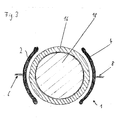
- a first electrode 2 and a second electrode 4 are arranged around the bottleneck 16 and at least partially surround the bottleneck 16 in the radial direction of the cork 18.
- a phase-shifted by 180 ° high-frequency signal is applied, which is generated by a high-frequency generator.
- the two electrodes 2, 4 also form a receiving area for receiving the bottle neck 16. Furthermore, the two electrodes may be arranged in a housing, wherein the housing may be formed so that it is an environment of the receiving area and the electrodes 2, 4 before the radiation protects.
- the two electrodes 2, 4 further form an excitation unit for generating high-frequency radiation in the receiving area. In order to achieve the most uniform expansion of the cork 18, it is expedient if either the two electrodes 2, 4 rotate during the irradiation time to the bottle 10 or the bottle 10 rotates.
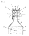
- FIG. 2 shows the device 1 according to FIG. 1 with a between the two electrodes 2, 4 applied by 180 ° shifted high-frequency alternating field 11th
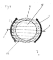
- FIG. 3 shows the device 1 according to FIG. 1 in plan view and FIG. 4 shows the device 1 according to FIG. 3 with the high-frequency alternating field 11.
- the high-frequency alternating field 11 is in the Figures 2 and 4 represented by several parallel arrows, wherein the direction of the field constantly changes by 180 °.
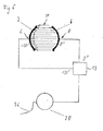
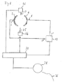
- FIG. 5 shows a simple block diagram of the in the FIGS. 1 to 4 shown device 1 according to various embodiments.
- the two electrodes 2, 4 are connected to a power divider phase shifter 13, which is connected to a high-frequency power generator 28.
- the power generator 28 is powered by a power supply 36.
- FIG. 6 shows an expanded block diagram of the in the FIGS. 1 to 5 shown device 1 according to various embodiments.
- a control unit 30 is inserted. It serves to regulate the high-frequency power generator 28.
- the power detector 44 has a measuring antenna 45.
- the temperature detector 46 has a temperature sensor 47.
- a high-frequency signal which is phase-shifted by 180 ° and is generated by the power generator 28 is applied to the two electrodes 2, 4.
- the electrodes 2, 4 should have the smallest possible capacitance to the mass of the housing, in which the electrodes 2, 4 are optionally installed. This can be done e.g. in that the distance to the mass of the housing is precisely defined in dependence on the wavelength of the radiation.
- the distance between the electrodes 2, 4 and the housing at a frequency of 2.45 GHz should be between 0.5 cm and 1 cm. Capacity losses could also be minimized by, for example, lining the inside of the housing with teflon.
- control unit 30 which is also called a controller and the detectors 44, 46
- actual parameters can be detected and readjusted to desired parameters.
- the electrical power between the two electrodes 2, 4 can be measured and compared with a predetermined desired value and, if necessary, the controller 28 then regulates the power.
- the temperature detector 46 for example an infrared sensor, the temperature of the bottleneck 16 can be measured and compared with a corresponding temperature setpoint, if necessary to change the power or the duration of the irradiation.
- an uneven expansion of the cork 18 can be achieved, for example by correspondingly forming the electrodes 2, 4.
- the cork 18 can be heated by means of the high-frequency radiation only in an axial section, so that the cork 18 expands substantially only in this axial section.
- an at least partially conical or conical cork 18 are formed. This can allow one from one Cork-piece formed cork 18 to use for closing a champagne bottle.
- the cork 18 may only be partially inserted into the bottle neck 16 so that an upper portion of the bottle neck 16 protrudes outwardly.
- a lower portion of the cork 18 is then located in the bottleneck of the champagne bottle. Thereupon, only the part of the cork 18 arranged in the bottleneck can be irradiated, whereby it heats up and expands and tightly seals the champagne bottle. Alternatively or additionally, the upper portion of the cork 18 may also be irradiated and expanded so that the enlarged cork 18 overlaps the edge of the bottle neck 16, resulting in the typical shape of a champagne bottle cork.
- FIG. 7 1 shows a block diagram of another device 1 for irradiating corks 18 in bottles 10 according to various embodiments.
- the cork 18 can be irradiated with high-frequency radiation, whereby the cork 18 heats up and expands.
- the expansion of the cork 18 in the bottle neck 16 results in a tight closure of the bottle 10.
- the bottleneck 16 with the cork 18 protrudes through an opening 21 into a cavity resonator, so that at least the part of the bottleneck 16 is surrounded in the radial direction by the cavity resonator 20 in which the cork 18 is arranged.
- the cavity 24 includes the receiving area for receiving the neck of the bottle 16. In other words, the receiving area may be formed by the cavity 24.
- a power generator 28 and the resonant cavity 20 are connected to each other via a coaxial cable 27.
- This coaxial cable 27 is supplied from the power generator 28 high-frequency power by means of a coupling antenna 26 in the cavity 20, which in this embodiment as Excitation unit serves.
- a waveguide could also be used as a connection between power generator 28 and the cavity 20, a waveguide could also be used.
- the high-frequency radiation may be, for example, in a frequency range between 10 kHz and 50 GHz, for example at 860 MHz or 2.45 GHz or 5.8 GHz, to name just a few frequencies.
- the power generator 28 is coupled to a control unit 30, via which a power 32 and a frequency 34 of the high-frequency radiation is regulated.
- the power 32 may be, for example, between 100 W and 5000 W, for example at 450 W or 600 W.
- the power generator 28 is further coupled to a power supply 36.
- the control unit 30 is a power setpoint 38 of the high-frequency radiation predetermined. Alternatively, the power setpoint 38 can be predetermined via the control unit 30.
- the control unit 30 is connected to a power detector 44 for detecting a power actual value 42 of the high-frequency radiation in the cavity 24 and for detecting a temperature 40 of the bottleneck 16 with a temperature detector 46.
- the power detector 44 is connected to detect a radiant power in the cavity resonator 20 with a measuring antenna 45 projecting thereinto.
- the temperature detector 46 includes a temperature sensor 47, wherein the temperature detector 46 and the temperature sensor 47, for example, are designed so that with their help from the cork 18 and / or the bottleneck 16 emitted infrared radiation can be detected.
- a device 1 is essentially predetermined, with the aid of which the high-frequency radiation in the cavity 20, in particular their power 32 and the frequency 34 is controllable.
- power detector 44 whose measuring antenna 45, and the temperature detector 46 and its temperature sensor 47, a regulation of the power of the high-frequency radiation and thus the controlled expansion of the cork 18 is possible.
- the Control unit 30 during operation to compare the actual power value 42 regularly with the power setpoint 38 and adjust the power 32 depending on the comparison, so that the actual power value 42 corresponds to the power setpoint 38.
- the power setpoint value 38 can be fixed, for example, or specified by a user of the device 1.
- the temperature 40 may also be a controlled variable, which is adjustable to a predetermined or adjustable temperature setpoint.
- the temperature 40 may be a control or safety variable, by which a safety limit is specified, which may not be exceeded, which when exceeded, a safety shutdown of the device 1 can take place.
- a maximum temperature of the heating of the bottle neck 16 can be predetermined, and if the detected temperature 40 reaches or exceeds the maximum temperature, the power generator 28 can be readjusted.
- the maximum temperature may be set so that upon irradiation of the cork 18, the glass of the bottle 10 will not burst.
- FIG. 8 shows a detailed view of the device 1 for irradiating corks 18 in bottles 10 according to FIG. 7 with electric field 50, which is represented by arrows, in particular the cavity resonator 20 with the bottle neck 16 received therein.
- the cavity resonator 20 has a first edge 54 and a second edge 56.
- the two edges 54, 56 are circular around the neck of the bottle 16 around.
- an electric field 50 is created in the cavity 24.
- the extent of the electric field 50 is determined by the distance between the two edges 54, 56.
- the distance between the two edges 54, 56 affects the penetration depth of the electric field 50 into the cork 18, causing the cork 18 to heat and expand.
- the socket 60 serves to connect the coaxial cable 27 to the coupling-in antenna 26 of the cavity resonator 20.
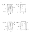
- FIG. 9 shows an example of a cork 18 inserted into the bottle neck 16 prior to treatment in one of the apparatuses 1 for irradiating corks 18 in bottles 10.
- the cork 18 may be introduced into the neck 16, for example, by mechanically compressing the cork 18 and then is introduced in the compressed state in the bottle neck 16, where the cork 18 expands again and the bottle neck 16 closes.
- the cork 18 may have tolerances and / or missed areas due to which liquid may escape from the bottle 10. As a result, the quality of the liquid 15 may deteriorate, for example, wine may taste like cork or spoil. Due to the tolerances, for example, a gap 70 between the cork 18 and an inner wall of the bottle neck 16 arise. The missing areas may consist of cracks or cavities 72, for example.
- FIG. 10 shows another example of a cork 18 introduced into the bottle neck 16 before irradiation, wherein in this cork 18, the gap 70 is formed on the top of the cork 18 and wherein the cork 18 additionally has a recess 73 on its outer side.
- FIG. 11 shows another example of a cork 18 introduced into the bottle neck 16 before treatment in one of the devices 1 for irradiating corks 18 in bottles 10, this cork having 18 recesses 73 on its outside and a cavity 72.
- FIGS. 9, 10 and 11 thus show simple examples of corks 18, where there is a fundamental risk that they do not permanently and / or hermetically seal the bottle 10, which in principle there is a risk that the liquid 15, in particular the wine, is damaged during storage.
- FIG. 12 shows an example of a cork 18 introduced into the bottle neck 16 after the irradiation.
- the cork 18 is close to the inner wall of the bottle neck 16 at its entire outer periphery.
- the cork 18 has neither cavities 72 nor recesses 73. Although there are still with the help of the device 1 closed cracks or cavities 74 recognizable, but these are so compressed that no liquid can escape from the bottle 10. In other words, the cork 18 seals the bottle 10 much better and more reliably than previously possible.
- the entire volume of the cork 18 increases.
- the cork 18 thus expands in all directions, in particular in the radial direction but also in the axial direction.
- the cork increases in the axial direction by an axial extent 76th
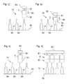
- FIG. 13 shows the device 1 for irradiating corks 18 in bottles 10 according to various embodiments in a first operating state, such as may be formed for closing a large number of bottles 10, for example.
- the device 1 is attached via a holding web 81 to a holding body 80.
- the device 1 has a radiation protection 83, which may be formed in a simple form as attached to the device 1 metallic cylinder.
- On a conveyor belt 82 are several bottles 10.
- the conveyor belt 82 moves the bottles 10 in a conveying direction 84.
- the device 1 can be moved by means of the holding body 80 along a stroke direction 86.
- the device 1 In the first operating state, the device 1 is in a position in which its lower edge and possibly a lower edge of the radiation protection 83 are arranged above the upper end of the bottles 10. The device 1 is moved in the stroke direction 86 towards the bottle 10, which is located just below the device 1.
- FIG. 14 shows the device 1 for irradiating corks 18 in bottles 10 according to FIG. 13 in a second operating state, in which the device 1 is arranged such that the bottle neck 16 of the bottle 10 with the cork 18 arranged therein is arranged in the cavity 24 of the device 1.
- the second operating state follows immediately after the first operating state.
- the cork 18 is irradiated by means of the high-frequency radiation.
- FIG. 15 shows the device 1 for irradiating corks 18 in bottles 10 according to FIG. 13 in a third operating state following the second operating state.
- the sealed bottle 10 is carried on and a new bottle 10 with an untreated cork 18 in its neck 16 is moved under the device 1.
- the individual bottles 10 are spaced from each other on the conveyor belt 82.
- the bottles 10 may also be arranged on the conveyor belt 82 so that they touch each other.
- the device 1 can also remain stationary, in which case the bottles 10 can be moved into and out of the device 1 in the vertical direction. An additional rotation of the bottle 10 about its longitudinal axis allows a more even expansion of the cork 18th
- FIG. 16 shows a front view of a possible embodiment of the embodiment according to FIG. 13 in which four devices 1 are arranged side by side.
- four juxtaposed bottles 10 can be simultaneously irradiated with high-frequency radiation and sealed. Behind it, more bottles can follow 10 in rows of four.
- FIG. 17 shows a device 1 for irradiating corks 18 in bottles 10 according to various embodiments in a view from below, wherein it is shown that a plurality of individual devices 1, for example twelve, in rows and Columns are arranged. As a result, a plurality of bottles 10, for example twelve, can be irradiated simultaneously and thus sealed.
- FIG. 18 shows a flowchart of a method for closing bottles 10 according to various embodiments.
- the method is suitable for tightly closing one or more bottles 10, for example wine bottles, after filling with the aid of one cork 18 each.
- the cork 18 is compressed in the radial direction so that its outer diameter is almost equal to or smaller than an inner diameter of the bottle neck 16.
- the outer diameter of the cork 18 can be selected in that the cork 18 is insertable into the bottle neck 16 without being compressed.
- the cork 18, optionally the compressed cork 18, is inserted into the false neck 16. If the cork 18 is not compressed, for example, the diameter of the cork 18 can be selected to be just as large that the cork 18 is easily, for example, without compression in the bottle neck 16 inserted.
- a relative movement takes place between the bottleneck 16 with the cork 18 arranged therein and the receiving area, for example the device 1, wherein the bottleneck 16 can be inserted into the receiving area, for example by lowering the device 1 with the receiving area or by lifting the bottle 10 , Depending on whether the cork 18 is to be irradiated completely or only in sections, the cork 18 arranged in the bottleneck 16 can be arranged completely or partially in the receiving area.
- the cork 18 is irradiated with the high-frequency radiation.
- the tightness required for sealing the bottle 10 expansion and Increase in the volume of the cork 18 can be achieved within a few seconds, with even higher power possibly even faster.
- the cork 18 may be irradiated and heated at a power of 600 W and a frequency of 2.45 GHz for 10 seconds. This leads to a volume increase of more than 25% in the case of a cork 18 arranged outside the bottle 10. If the cork 18 is disposed in the neck 16, increasing the volume of the cork 18 results in the tighter closure of the bottle 10.
- the glass of the bottle 10 is penetrated by the high frequency radiation without major losses.
- the liquid 15, especially the wine is not heated and thus suffers no loss of quality.
- the degree of expansion of the cork 18 can be accurately determined due to the precise controllability of the high frequency radiation. In this way, differently shaped bottles with different dimensions better than previously sealed.
- a step S10 the bottleneck 16 of the sealed bottle 10 is removed from the receiving area.
- corks 18 can be used to advantage even before the corks are introduced into bottles, as compared to conventional corks 18 only corks 18 with smaller diameters are needed.
- the diameter of the cork 18 may even be smaller than the inner diameter of the bottle 10 to be closed.
- the corks 18 can then be enlarged prior to insertion into the bottles 10 by means of the high-frequency radiation and then introduced, for example by means of the conventional pressing method in the bottle necks 16 and the bottles 10 can be closed in a conventional manner with the enlarged cork 18 and
- the bottles 10 may additionally or alternatively be closed by means of the enlarged corks 18 and the method explained above.
- the enlargement of the cork 18 takes place in two steps, unless the maximum extent of the cork 18 is brought about in the first step.
- the cork 18 is briefly irradiated with high-frequency energy, so that it heats up and increases its volume up to a predetermined target diameter.
- the cork 18 is then inserted into the neck of the bottle 16 and irradiated again so that it expands again and the bottle 10 is thus sealed.
- cork enlargement can generally be used to advantage regardless of capping bottles 10.
- the natural cork which is extracted from the bark of the cork oak, is a precious and expensive raw material. No matter what this precious raw material is used for, for example, as a floor covering or wall or ceiling paneling, increasing its volume can help to increase the amount of cork raw material, for example cork granules, by more than 25% Cork end products to produce.
- the invention is not limited to the specified embodiments.
- the cork pieces can be increased before gluing or pressing and / or after gluing.
- more electrodes 2, 4 may be provided and / or the electrodes 2, 4 may have a different shape.
- the shape of the device 1 may vary and / or the specified method for closing the bottles 10 may have additional or alternatively steps.
- the liquid 15 may also include vinegar, oil, brandy, etc.
Landscapes
- Engineering & Computer Science (AREA)
- Mechanical Engineering (AREA)
- Constitution Of High-Frequency Heating (AREA)
- Closures For Containers (AREA)
Abstract
Bei einem Verfahren zum Vergrößern des Volumens von Korken wird dieser einer hochfrequenten Strahlung mit bestimmter Leistung für kurze Zeit ausgesetzt. Dabei erwärmt sich der Korken und vergrößert sein Volumen. Der gleiche Effekt tritt nicht nur bei Einzelkorken sondern auch bei Korkplatten oder Korkstreifen auf. Befindet sich der Korken bereits in einem Flaschenhals, so kann er sich nur begrenzt ausdehnen, wodurch Hohlräume und Risse in dem Korken verschlossen oder minimiert werden. Zudem werden bei hochfrequenter Bestrahlung von Kork schädliche Mikroorganismen abgetötet. Beide Effekte führen zu einer wesentlichen Verbesserung der Qualität von Korken und erlauben damit ein zuverlässigeres Verschließen von zum Beispiel Weinflaschen.

Description
Der Erfindung zugrunde liegt die Erkenntnis des Erfinders, dass sich Kork bei Bestrahlung mit hochfrequenter Strahlung bei genügend Leistung ausdehnt.The invention is based on the knowledge of the inventor that cork expands upon irradiation with high-frequency radiation with sufficient power.
Die Erfindung betrifft ein Verfahren zum Verschließen von Flaschen mit Korken und eine Vorrichtung zum Bestrahlen von Korken in Flaschen.The invention relates to a method for closing bottles with corks and a device for irradiating corks in bottles.
Wenn in dieser Patentschrift von hochfrequenter Strahlung bzw. von hochfrequenter Leistung geschrieben wird, so ist damit auch die Mikrowellenstrahlung einbezogen, die im üblichen Sprachgebrauch ab etwa 1 GHz beginnt.When writing in this patent of high-frequency radiation or high-frequency power, as well as the microwave radiation is included, which begins in the usual parlance from about 1 GHz.
Aus
Der Kork für Korken wird aus der Rinde der Korkeiche gewonnen und ist ein teures Naturprodukt. Korkrinde wird zu Korkstreifen geschnitten, aus denen die Korken herausgestanzt werden. Anschließend werden die Korken verschiedenen bekannten Prozeduren unterzogen, auf die hier nicht näher eingegangen wird, damit sie zum Abdichten von Weinflaschen geeignet sind. Es können nur Korken verwendet werden, die bestimmte Qualitätskriterien erfüllen, wie zum Beispiel geringe Feuchtigkeit, kein Schimmelpilzbefall, keine zu großen Risse und Hohlräume, nur um einige zu nennen.The cork for corks is obtained from the bark of cork oak and is an expensive natural product. Cork bark is cut into cork strips from which the corks are punched out. Subsequently, the corks are subjected to various known procedures, which are not discussed here, so that they are suitable for sealing wine bottles. Only corks that meet certain quality criteria can be used, such as low humidity, no mold infestation, no large cracks and cavities, just to name a few.
Es ist eine bekannte Tatsache, dass durch undichte oder verdorbene Korken den Winzern und der Weinindustrie jedes Jahr Schäden in Millionenhöhe entstehen. Bei den derzeit üblichen Verfahren zum Verschließen von Weinflaschen werden Korken durch eine mechanische Vorrichtung zusammengepresst und in die Flaschenhälse der Flaschen eingeführt. Problematisch ist, dass Korken Toleranzen in der Länge und in den Durchmessern sowie kleine Hohlräume und Risse aufweisen. Dies kann dazu führen, dass die Flaschen nicht richtig verschlossen werden und es zu Undichtigkeiten kommt.It is a well-known fact that leaking or spoiling corks causes wine-growers and the wine industry millions of dollars each year. In the currently used methods for closing wine bottles, corks are pressed together by a mechanical device and inserted into the bottlenecks of the bottles. The problem is that corks have tolerances in length and in diameters, as well as small cavities and cracks. This can do this cause bottles not to close properly and leaks.
Als Lösung dieses Problems wird ein Korken, der ganz oder teilweise in einem Flaschenhals steckt, mittels hochfrequenter Strahlung ganz oder teilweise bestrahlt, so dass er sich ausdehnt. Da dies in einem Flaschenhals nur sehr begrenzt möglich ist, verdichtet sich das Volumen des Korkens wodurch Hohlräume und Risse im Korken geschlossen oder minimiert werden. Dadurch wird die Qualität des Verschlusses mittels des Korkens gesteigert und die Flasche besser und sicherer abgedichtet. Durch dieses Verfahren lassen sich zukünftig Flaschen, insbesondere Weinflaschen sicherer und dauerhafter verschließen als es bislang möglich war.As a solution to this problem, a cork, which is wholly or partially in a bottleneck, irradiated in whole or in part by high-frequency radiation, so that it expands. Since this is only possible to a very limited extent in a bottleneck, the volume of the cork is compressed, whereby cavities and cracks in the cork are closed or minimized. As a result, the quality of the closure is increased by means of the cork and sealed the bottle better and safer. In the future, bottles, in particular wine bottles, can be sealed in a safer and more durable manner than was previously possible with this method.
Hochfrequente Strahlung hat die Eigenschaft, dass sie das Flaschenglas ohne große Dämpfungsverluste durchdringt. Bei der Bestrahlung durch hochfrequente Strahlung ist zudem nur ein eng begrenzter Teil des Flaschenhalses einschließlich des darin steckenden Korkens betroffen und nicht die restliche Flasche, wodurch eine unerwünschte Erwärmung der sich in der Flasche befindenden Flüssigkeit, beispielsweise von Wein, vermieden wird.High-frequency radiation has the property that it penetrates the bottle glass without much attenuation losses. Irradiation by radiofrequency radiation also affects only a narrow part of the neck of the bottle, including the cork in it, and not the rest of the bottle, thus avoiding unwanted heating of the liquid in the bottle, such as wine.
So konnte mit einem handelsüblichen Mikrowellenofen das Volumen eines Korkens, der bei 2,45 GHz für 10 Sekunden mit 600 Watt bestrahlt wurde, um mindestens 25 % dauerhaft vergrößert werden, ohne dass der Korken dabei überhitzt wurde, oder sonstige Schäden oder Einbußen an seiner Elastizität erkennbar waren.For example, with a commercial microwave oven, the volume of a cork irradiated at 2.45GHz for 10 seconds at 600 watts could be permanently increased by at least 25% without overheating the cork, or otherwise damage or loss of elasticity were recognizable.
Ein weiterer, aber bereits bekannter Vorteil der Bestrahlung von Korken durch hochfrequente Strahlung ist die Abtötung von schädlichen Mikrobakterien, die sich im Innern des Korkens befinden. Diese Mikroorganismen sind relativ häufig dafür verantwortlich, dass Korken stark geschädigt werden und der Wein, der sich in diesen Flaschen befindet, Qualitätseinbußen erleidet oder sogar ungenießbar wird.Another, but already known, advantage of high-frequency radiation exposure of corks is the killing of harmful microbial bacteria located inside the cork. These microorganisms are relatively often responsible for the fact that corks are severely damaged and the wine that is in these bottles suffers quality loss or even becomes inedible.
Das Verfahren hat zudem noch den Vorteil, dass man die Ausdehnung des Korkens bis zu einem gewissen Grad bestimmen kann, weil man die Frequenz, sowie die Leistung und die Zeit der hochfrequenten Bestrahlung sehr genau regeln kann. Wie lange und bei welcher Leistung Korken in Flaschenhälsen bestrahlt werden sollen, um ein optimales Ergebnis zu erreichen, kann einfach empirisch, insbesondere durch Tests, beispielsweise abhängig vom Flaschenhalsdurchmesser und der Korkengröße ermittelt werden.In addition, the method has the advantage that it is possible to determine the extent of the cork to a certain degree, because it is possible to regulate the frequency as well as the power and the time of the high-frequency irradiation very precisely. How long and at what capacity corks in bottle necks are to be irradiated in order to achieve an optimum result can easily be determined empirically, in particular by tests, for example, depending on bottle neck diameter and cork size.
Mit hochfrequenter Strahlung kann man zum Beispiel auch nur eine Hälfte des Korkens vergrößern, während die andere Hälfte praktisch unverändert bleibt. Bei genau abgestimmter Positionierung der hochfrequenten Bestrahlung, die durch geeignete Anordnung von Elektroden zu erreichen ist, lässt sich sogar die Form des Korkens verändern. Damit wäre es zum Beispiel möglich, einen Naturkorken so zu bestrahlen, dass er eine ähnliche Form bekommt wie ein in Champagner Flaschen verwendeter Presskorken. Dies würde es der Schaumweinindustrie ermöglichen, zukünftig Naturkorken zum Abdichten der Schaumwein-Flaschen zu verwenden und nicht wie heute üblich Presskorken. Diese bestehen größtenteils aus zusammengepressten Korkabfällen und Korkstaub. Ein in der Form passender Naturkorken könnte ein weiteres Qualitätsmerkmal von Schaumweinen werden.With high-frequency radiation, for example, you can only enlarge one half of the cork, while the other half remains virtually unchanged. By properly positioning the high-frequency radiation, which can be achieved by suitable arrangement of electrodes, even the shape of the cork can be changed. Thus, it would be possible, for example, to irradiate a natural cork so that it gets a similar shape as a cork used in champagne bottles. This would allow the sparkling wine industry to use natural corks for sealing the sparkling wine bottles in the future, rather than press corks as is common today. These consist mainly of compressed cork waste and cork dust. A natural cork matching the shape could be another quality feature of sparkling wines.
Beispielhaft werden in einigen Ausführungen Vorrichtungen gezeigt, die das vorher beschriebene Verfahren zum Erwärmen von Korken mittels hochfrequenter Strahlung in Flaschenhälsen ermöglichen würden. Diese Vorrichtungen sind nur beispielhaft und erheben keinen Anspruch auf technische Vollständigkeit.By way of example, in some embodiments, devices are shown which would enable the previously described method of heating corks by means of high frequency radiation in bottlenecks. These devices are exemplary only and do not claim to be technical.
Es zeigen:
Figur 1- eine Seitenansicht einer Vorrichtung zum Bestrahlen von Korken in Flaschen gemäß verschiedenen Ausführungsbeispielen;
Figur 2- eine weitere Seitenansicht der Vorrichtung gemäß
Figur 1 - Figur 3
- eine Draufsicht der Vorrichtung gemäß
Figur 1 Figur 4- eine weitere Draufsicht der Vorrichtung gemäß
Figur 3 ; Figur 5- ein Blockschaltbild der Vorrichtung gemäß verschiedenen Ausführungsbeispielen;
Figur 6- ein weiteres Blockschaltbild der Vorrichtung gemäß verschiedenen Ausführungsbeispielen;
Figur 7- eine Vorrichtung zum Bestrahlen von Korken Flaschen gemäß verschiedenen Ausführungsbeispielen;
Figur 8- eine Detailansicht der Vorrichtung gemäß
Figur 7 - Figur 9
- ein Beispiel für einen Korken in einem Flaschenhals;
Figur 10- ein Beispiel für einen Korken in einem Flaschenhals;
Figur 11- ein Beispiel für einen Korken in einem Flaschenhals;
Figur 12- ein Beispiel für einen Korken in einem Flaschenhals;
Figur 13- eine Vorrichtung zum Bestrahlen von Korken in Flaschen gemäß verschiedenen Ausführungsbeispielen in einem ersten Betriebszustand;
Figur 14- die Vorrichtung gemäß
Figur 13 Figur 15- die Vorrichtung gemäß
Figur 13 Figur 16- eine Vorrichtung zum Bestrahlen von Korken in Flaschen gemäß verschiedenen Ausführungsbeispielen;
- Figur 17
- eine Vorrichtung zum Bestrahlen von Korken in Flaschen gemäß verschiedenen Ausführungsbeispielen;
Figur 18- ein Ablaufdiagramm eines Verfahrens zum Verschließen von Flaschen gemäß verschiedenen Ausführungsbeispielen.
- FIG. 1
- a side view of an apparatus for irradiating corks in bottles according to various embodiments;
- FIG. 2
- a further side view of the device according to
FIG. 1 ; - FIG. 3
- a plan view of the device according to
FIG. 1 ; - FIG. 4
- a further plan view of the device according to
FIG. 3 ; - FIG. 5
- a block diagram of the device according to various embodiments;
- FIG. 6
- another block diagram of the device according to various embodiments;
- FIG. 7
- a device for irradiating cork bottles according to various embodiments;
- FIG. 8
- a detailed view of the device according to
FIG. 7 ; - FIG. 9
- an example of a cork in a bottleneck;
- FIG. 10
- an example of a cork in a bottleneck;
- FIG. 11
- an example of a cork in a bottleneck;
- FIG. 12
- an example of a cork in a bottleneck;
- FIG. 13
- an apparatus for irradiating corks in bottles according to various embodiments in a first operating state;
- FIG. 14
- the device according to
FIG. 13 in a second operating state; - FIG. 15
- the device according to
FIG. 13 in a third operating condition; - FIG. 16
- an apparatus for irradiating corks in bottles according to various embodiments;
- FIG. 17
- an apparatus for irradiating corks in bottles according to various embodiments;
- FIG. 18
- a flowchart of a method for closing bottles according to various embodiments.
In der folgenden ausführlichen Beschreibung wird auf die beigefügten Zeichnungen Bezug genommen, die Teil dieser bilden und in denen zur Veranschaulichung spezifische Ausführungsformen gezeigt sind, in denen die Erfindung ausgeübt werden kann. In dieser Hinsicht wird Richtungsterminologie wie etwa "oben", "unten", "vorne", "hinten", "vorderes", "hinteres", usw. mit Bezug auf die Orientierung der beschriebenen Figur(en) verwendet. Da Komponenten von Ausführungsformen in einer Anzahl verschiedener Orientierungen positioniert werden können, dient die Richtungsterminologie zur Veranschaulichung und ist auf keinerlei Weise einschränkend. Es versteht sich, dass die Merkmale der hierin beschriebenen verschiedenen beispielhaften Ausführungsformen miteinander kombiniert werden können, sofern nicht spezifisch anders angegeben. Die folgende ausführliche Beschreibung ist deshalb nicht in einschränkendem Sinne aufzufassen, und der Schutzumfang der vorliegenden Erfindung wird durch die angefügten Ansprüche definiert.In the following detailed description, reference is made to the accompanying drawings, which form a part hereof, and in which is shown by way of illustration specific embodiments in which the invention may be practiced. In this regard, directional terminology such as "top", "bottom", "front", "back", "front", "rear", etc. is used with reference to the orientation of the described figure (s). Because components of embodiments can be positioned in a number of different orientations, the directional terminology is illustrative and is in no way limiting. It should be understood that the features of the various exemplary embodiments described herein may be combined with each other unless specifically stated otherwise. The following detailed description is therefore not to be taken in a limiting sense, and the scope of the present invention is defined by the appended claims.
Im Rahmen dieser Beschreibung werden Begriffe wie "angeschlossen" sowie "eingekoppelt" verwendet zum Beschreiben sowohl eines direkten oder indirekten Anschlusses sowie einer direkten oder indirekten Kopplung. In den Figuren werden identische oder ähnliche Elemente mit identischen Bezugszeichen versehen, soweit dies zweckmäßig ist.In the context of this description, terms such as "connected" and "coupled" are used to describe both a direct or indirect connection and a direct or indirect coupling. In the figures, identical or similar elements are provided with identical reference numerals, as appropriate.
Eine erste Elektrode 2 und eine zweite Elektrode 4 sind um den Flaschenhals 16 herum angeordnet und umgeben den Flaschenhals 16 in radialer Richtung des Korkens 18 zumindest teilweise. An beide Elektroden 2, 4 wird ein um 180° phasenverschobenes Hochfrequenzsignal angelegt, das von einem Hochfrequenzgenerator erzeugt wird.A
Die beiden Elektroden 2, 4 bilden zugleich einen Aufnahmebereich zum Aufnehmen des Flaschenhalses 16. Ferner können die beiden Elektroden in einem Gehäuse angeordnet sein, wobei das Gehäuse so ausgebildet sein kann, dass es eine Umgebung des Aufnahmebereichs und der Elektroden 2, 4 vor der Strahlung schützt. Die beiden Elektroden 2, 4 bilden weiter eine Anregungseinheit zum Erzeugen hochfrequenter Strahlung in dem Aufnahmebereich. Um eine möglichst gleichmäßige Ausdehnung des Korkens 18 zu erreichen, ist es zweckmäßig, wenn sich entweder die beiden Elektroden 2, 4 während der Bestrahlungszeit um die Flasche 10 drehen oder die Flasche 10 sich dreht.The two
Die Funktionsweise der vorstehend erläuterten Vorrichtung 1 ist folgende: An den beiden Elektroden 2, 4 wird ein um 180° phasenverschobenes Hochfrequenzsignal angelegt, das von dem Leistungsgenerator 28 erzeugt wird.The operation of the
Dadurch entsteht ein hochfrequentes elektrisches Wechselfeld zwischen beiden Elektroden 2, 4, das zum Beispiel bei einer Frequenz von 2,45 GHz, also 2,45 x 10⁹ mal in der Sekunde, um 180° die Richtung wechselt. Dadurch werden, wenn das Hochfrequenzsignal genügend Leistung aufweist und damit das elektrische Wechselfeld genügend stark ist, im Korken 18 Wassermoleküle durch Reibung erhitzt, was zu einer Erwärmung und zu einer Ausdehnung des Korkens 18 führt. Es ist jedoch nicht ausgeschlossen, dass und gegebenenfalls in wie weit im Korken 18 vorhandene Mikroorganismen dazu beitragen, dass sich der Korken 18 bei Bestrahlung ausdehnt.This creates a high-frequency alternating electric field between the two
Um die elektrischen Verluste möglichst gering zu halten und einen hohen Wirkungsgrad zu erzielen, sollten die Elektroden 2, 4 eine möglichst geringe Kapazität zu der Masse des Gehäuses aufweisen, in das die Elektroden 2, 4 gegebenenfalls eingebaut werden. Dies kann man z.B. dadurch erreichen, dass der Abstand zu der Masse des Gehäuses genau definiert wird in Abhängigkeit zur Wellenlänge der Strahlung. So sollte der Abstand zwischen den Elektroden 2, 4 und dem Gehäuse bei einer Frequenz von 2,45 GHz zwischen 0,5 cm und 1 cm sein. Die Kapazitätsverluste ließen sich auch minimieren, indem man zum Beispiel das Gehäuseinnere mit Teflon auskleidet. Zu beachten ist auch der Abstand beider Elektroden 2, 4 zueinander, wobei der Abstand in dem vorstehend gezeigten Ausführungsbeispiel durch den Durchmesser des von den Elektroden 2, 4 teilweise umschlossenen Kreises gegeben ist. Dieser Durchmesserabstand sollte zum Beispiel bei einer Frequenz von 2,45 GHz in etwa 3 cm betragen, was etwas weniger als einer viertelt Wellenlänge entspricht.In order to keep the electrical losses as low as possible and to achieve high efficiency, the
Mit Hilfe der Steuereinheit 30, die auch Controller genannt wird und den Detektoren 44, 46 lassen sich Ist-Parameter erfassen und auf Soll-Parameter nachregeln. So kann zum Beispiel die elektrische Leistung zwischen beiden Elektroden 2, 4 gemessen und mit einem vorgegeben Sollwert verglichen werden und falls nötig regelt dann das Steuergerät 28 die Leistung nach. Weiter kann mittels des Temperaturdetektors 46, beispielsweise einem Infrarotsensor, die Temperatur des Flaschenhalses 16 gemessen und mit einem entsprechenden Temperatur-Sollwert verglichen werden, um falls nötig die Leistung oder die Dauer der Bestrahlung zu ändern.By means of the
Alternativ zu der gleichmäßigen Ausdehnung mit Hilfe der hochfrequenten Strahlung kann eine ungleichmäßige Ausdehnung des Korkens 18 erzielt werden, beispielsweise durch entsprechendes Ausbilden der Elektroden 2, 4. Beispielsweise kann der Korken 18 mit Hilfe der hochfrequenten Strahlung nur in einem axialen Teilabschnitt erwärmt werden, so dass sich der Korken 18 im Wesentlichen nur in diesem axialen Teilabschnitt ausdehnt. Dadurch kann beispielsweise aus einem vollständig zylindrischen Korken 18 beispielsweise ein zumindest teilweise konischer oder kegelförmiger Korken 18 gebildet werden. Dies kann ermöglichen, einen aus einem Kork-Stück gebildeten Korken 18 zum Verschließen einer Champagner-Flasche zu verwenden. Beispielsweise kann der Korken 18 nur teilweise in den Flaschenhals 16 eingeführt werden, so dass ein oberer Abschnitt aus dem Flaschenhals 16 nach außen hervorsteht. Ein unterer Abschnitt des Korkens 18 ist dann in dem Flaschenhals der Champagner-Flasche angeordnet. Daraufhin kann ausschließlich der in dem Flaschenhals angeordnete Teil des Korkens 18 bestrahlt werden, wodurch sich dieser erwärmt und ausdehnt und die Champagner-Flasche dicht verschließt. Alternativ oder zusätzlich kann auch der obere Abschnitt des Korkens 18 bestrahlt und ausgedehnt werden, so dass der vergrößerte Korken 18 den Rand des Flaschenhalses 16 überlappt, was zur typischen Form eines Champagner-Flaschen Korken führt.As an alternative to the uniform expansion with the aid of the high-frequency radiation, an uneven expansion of the
Der Flaschenhals 16 mit dem Korken 18 ragt durch eine Öffnung 21 in einen Hohlraumresonator hinein, so dass zumindest der Teil des Flaschenhalses 16 in radialer Richtung von dem Hohlraumresonator 20 umgeben ist, in dem der Korken 18 angeordnet ist. Der Hohlraumresonator 20, insbesondere der Hohlraum 24 des Hohlraumresonators 20 ist beispielsweise um eine Symmetrieachse 19 des Korkens 18 oder des Flaschenhalses 16 rotationssymmetrisch, also kreisrund, ausgebildet. Der Hohlraum 24 umfasst den Aufnahmebereich zum Aufnehmen des Flaschenhalses 16. In anderen Worten kann der Aufnahmebereich durch den Hohlraum 24 gebildet sein.The
Ein Leistungsgenerator 28 und der Hohlraumresonator 20 sind über ein Koaxialkabel 27 miteinander verbunden. Über dieses Koaxialkabel 27 wird vom Leistungsgenerator 28 hochfrequente Leistung mittels einer Einkoppelantenne 26 in den Hohlraumresonator 20 eingespeist, die bei diesem Ausführungsbeispiel als Anregungseinheit dient. Als Verbindung zwischen Leistungsgenerator 28 und dem Hohlraumresonator 20 könnte auch ein Hohlleiter verwendet werden.A
Die hochfrequente Strahlung kann beispielsweise in einem Frequenzbereich zwischen 10 KHz und 50 GHz, beispielsweise bei 860 MHz oder 2,45 GHz oder 5,8 GHz, um nur einige Frequenzen zu nennen, liegen. Der Leistungsgenerator 28 ist mit einer Steuereinheit 30 gekoppelt, über die eine Leistung 32 und eine Frequenz 34 der hochfrequenten Strahlung geregelt wird. Die Leistung 32 kann beispielsweise zwischen 100 W und 5000 W liegen, beispielsweise bei 450 W oder 600 W. Zum Erzeugen der hochfrequenten Strahlung ist der Leistungsgenerator 28 weiter mit einer Strom- bzw. Spannungsversorgung 36 gekoppelt. Der Steuereinheit 30 ist ein Leistungs-Sollwert 38 der hochfrequenten Strahlung vorgegeben. Alternativ dazu kann der Leistungs-Sollwert 38 über die Steuereinheit 30 vorgebbar sein.The high-frequency radiation may be, for example, in a frequency range between 10 kHz and 50 GHz, for example at 860 MHz or 2.45 GHz or 5.8 GHz, to name just a few frequencies. The
Die Steuereinheit 30 ist zum Erfassen eines Leistungs-Istwerts 42 der hochfrequenten Strahlung in dem Hohlraum 24 mit einem Leistungsdetektor 44 und zum Erfassen einer Temperatur 40 des Flaschenhalses 16 mit einem Temperaturdetektor 46 verbunden. Der Leistungsdetektor 44 ist zum Erfassen der Strahlungsleistung in den Hohlraumresonator 20 mit einer in diesen ragenden Messantenne 45 verbunden. Der Temperaturdetektor 46 umfasst einen Temperaturfühler 47, wobei der Temperaturdetektor 46 und der Temperaturfühler 47 beispielsweise so ausgebildet sind, dass mit ihrer Hilfe von dem Korken 18 und/oder dem Flaschenhals 16 abgegebene Infrarotstrahlung erfassbar ist.The
Durch die Steuereinheit 30, den Leistungsgenerator 28, die Einkoppelantenne 26 und den Hohlraumresonator 20 ist im Wesentlichen eine Vorrichtung 1 vorgegeben, mit deren Hilfe die hochfrequente Strahlung in dem Hohlraumresonator 20, insbesondere deren Leistung 32 und deren Frequenz 34 steuerbar ist. Mittels Leistungsdetektor 44, dessen Messantenne 45, und den Temperaturdetektor 46 und dessen Temperaturfühler 47 ist eine Regelung der Leistung der hochfrequenten Strahlung und damit der kontrollierten Ausdehnung des Korkens 18 möglicht. Beispielsweise kann die Steuereinheit 30 im Betrieb den Leistungs-Istwert 42 regelmäßig mit dem Leistungs-Sollwert 38 vergleichen und die Leistung 32 abhängig von dem Vergleich anpassen, so dass der Leistungs-Istwert 42 dem Leistungs-Sollwert 38 entspricht. Der Leistungs-Sollwert 38 kann beispielsweise fest vorgegeben sein oder von einem Anwender der Vorrichtung 1 vorgegeben werden. Die Temperatur 40 kann ebenfalls eine Regelgröße sein, die auf einen vorgegebenen oder einstellbaren Temperatur-Sollwert regelbar ist. Alternativ dazu kann die Temperatur 40 eine Kontroll- oder Sicherheitsgröße sein, durch die ein Sicherheitsgrenzwert vorgegeben ist, der nicht überschritten werden darf, wobei bei dessen Überschreitung eine Sicherheitsabschaltung der Vorrichtung 1 erfolgen kann. In anderen Worten kann eine maximale Temperatur der Erwärmung des Flaschenhalses 16 vorgegeben werden und falls die erfasste Temperatur 40 die maximale Temperatur erreicht oder überschreitet, kann der Leistungsgenerator 28 nachgeregelt werden. Die maximale Temperatur kann beispielsweise so vorgegeben werden, dass beim Bestrahlen des Korkens 18 das Glas der Flasche 10 nicht zerspringt.By the
An einer Seite des Hohlraumresonators 20 ist eine Buchse 60 befestigt. Die Buchse 60 dient zum Verbinden des Koaxialkabels 27 mit der Einkoppelantenne 26 des Hohlraumresonators 20.On one side of the
Der Korken 18 kann Toleranzen und/oder Fehlbereiche aufweisen, aufgrund derer Flüssigkeit aus der Flasche 10 austreten kann. Dadurch kann sich die Qualität der Flüssigkeit 15 verschlechtern, beispielsweise kann Wein nach Kork schmecken oder verderben. Aufgrund der Toleranzen kann beispielsweise ein Spalt 70 zwischen dem Korken 18 und einer Innenwand des Flaschenhalses 16 entstehen. Die Fehlbereiche können beispielsweise aus Rissen oder Hohlräumen 72 bestehen.The
Die
Bei der Behandlung des Korkens 18 mit Hilfe einer der Vorrichtungen 1 vergrößert sich das gesamte Volumen des Korkens 18. Der Korken 18 dehnt sich somit in alle Richtungen aus, insbesondere in radialer Richtung aber auch in axialer Richtung. Beispielsweise vergrößert sich der Korken in axialer Richtung um eine axiale Ausdehnung 76.In the treatment of the
In den
In einem Schritt S2, der optional ausgeführt werden kann, wird der Korken 18 derart in radialer Richtung zusammengepresst, dass sein äußerer Durchmesser nahezu gleich oder kleiner ist als ein innerer Durchmesser des Flaschenhalses 16. Alternativ dazu kann der äußere Durchmesser des Korkens 18 so gewählt werden, dass der Korken 18 ohne Zusammenpressen in den Flaschenhals 16 einführbar ist.In a step S2, which can optionally be carried out, the
In einem Schritt S4 wird der Korken 18, gegebenenfalls der zusammengepresste Korken 18, in den Falschenhals 16 eingeführt. Falls der Korken 18 nicht zusammengepresst wird, kann beispielsweise der Durchmesser des Korkens 18 genau so groß gewählt werden, dass der Korken 18 leicht, beispielsweise ohne Zusammenpressen in den Flaschenhals 16 einführbar ist.In a step S4, the
In einem Schritt S6 erfolgt eine Relativbewegung zwischen dem Flaschenhals 16 mit dem darin angeordneten Korken 18 und dem Aufnahmebereich, beispielsweise der Vorrichtung 1, wobei der Flaschenhals 16 beispielsweise durch Absenken der Vorrichtung 1 mit dem Aufnahmebereich oder durch Anheben der Flasche 10 in den Aufnahmebereich einführbar ist. Abhängig davon, ob der Korken 18 vollständig oder nur abschnittsweise bestrahlt werden soll, kann der in dem Flaschenhals 16 angeordnete Korken 18 vollständig oder teilweise in dem Aufnahmebereich angeordnet werden.In a step S6, a relative movement takes place between the
In einem Schritt S8 wird der Korken 18 mit der hochfrequenten Strahlung bestrahlt. Die zum dichten Verschließen der Flasche 10 benötigte Ausdehnung und Vergrößerung des Volumens des Korkens 18 kann innerhalb von wenigen Sekunden, bei größerer Leistung womöglich sogar noch schneller, erreicht werden. Beispielsweise kann der Korken 18 mit einer Leistung von 600 W und einer Frequenz von 2,45 GHz 10 Sekunden lang bestrahlt und erwärmt werden. Dies führt bei einem außerhalb der Flasche 10 angeordneten Korken 18 zu einer Volumenvergrößerung von mehr als 25 %. Ist der Korken 18 in dem Flaschenhals 16 angeordnet, so führt die Vergrößerung des Volumens des Korkens 18 zu dem dichteren Verschließen der Flasche 10. Das Glas der Flasche 10 wird von der hochfrequenten Strahlung ohne größere Verluste durchdrungen. Die Flüssigkeit 15, insbesondere der Wein, wird dabei nicht erwärmt und erleidet damit keine Qualitätseinbuße. Der Grad der Ausdehnung des Korkens 18 kann aufgrund der genauen Regelbarkeit der hochfrequenten Strahlung genau bestimmt werden. Auf diese Weise können auch unterschiedlich geformte Flaschen mit unterschiedlichen Ausmaßen besser als bisher dicht verschlossen werden.In a step S8, the
In einem Schritt S10 wird der Flaschenhals 16 der dichten Flasche 10 aus dem Aufnahmebereich entfernt.In a step S10, the
Das Vergrößern des Volumens von Korken 18 kann schon vor dem Einführen der Korken in Flaschen vorteilhaft genutzt werden, da gegenüber herkömmlichen Korken 18 nur noch Korken 18 mit geringeren Durchmessern benötigt werden. Der Durchmesser des Korkens 18 kann sogar kleiner als der Innendurchmesser der zu verschließenden Flasche 10 gewählt werden. So können aus einer vorgegebenen Menge an Kork-Rohstoff mehr Korken 18 als bisher gewonnen werden, wodurch Kosten gespart werden können. Die Korken 18 können dann vor dem Einführen in die Flaschen 10 mit Hilfe der hochfrequenten Strahlung vergrößert werden und dann beispielsweise mit Hilfe des herkömmlichen Pressverfahrens in die Flaschenhälse 16 eingeführt werden und die Flaschen 10 können so auf herkömmliche Weise mit den vergrößerten Korken 18 verschlossen werden und/oder die Flaschen 10 können zusätzlich oder alternativ mit Hilfe der vergrößerten Korken 18 und des vorstehend erläuterten Verfahrens verschlossen werden.Increasing the volume of
Möglich wäre zum Beispiel auch, dass die Vergrößerung des Korkens 18 in zwei Schritten erfolgt, sofern man nicht gleich im ersten Schritt die maximale Ausdehnung des Korkens 18 herbeiführt. Als erster Schritt wird der Korken 18 kurzeitig mit hochfrequenter Energie bestrahlt, so dass er sich erwärmt und sein Volumen bis zu einem vorgegeben Solldurchmesser vergrößert. Als zweiten Schritt wird der Korken 18 dann in den Flaschenhals 16 eingeführt und erneut bestrahlt, damit er sich nochmal ausdehnt und die Flasche 10 damit dicht verschlossen wird.It would also be possible, for example, that the enlargement of the
Ferner kann das Vergrößern von Kork im Allgemeinen unabhängig von dem Verschließen von Flaschen 10 vorteilhaft genutzt werden. Der natürliche Kork, der aus der Rinde der Korkeiche gewonnen wird, ist ein kostbarer und teurer Rohstoff. Egal für was dieser kostbare Rohstoff genutzt wird, beispielsweise als Bodenbelag oder als Wand- oder Deckenverkleidung, kann das Vergrößern seines Volumens dazu beitragen, aus einer bestimmten Menge Kork-Rohstoff, zum Beispiel Kork-Granulat, eine um mehr als 25 % größere Menge an Kork-Endprodukten zu erzeugen.Further, cork enlargement can generally be used to advantage regardless of capping
Die Erfindung ist nicht auf die angegebenen Ausführungsbeispiele beschränkt. Beispielsweise kann als Korken 18 ein Agglomerat-Korken verwendet werden, der aus vielen Korkstücken zusammengeklebt ist. Dabei können die Korkstücke vor dem Verkleben bzw. Verpressen und/oder nach dem Verkleben vergrößert werden. Ferner können mehr Elektroden 2, 4 vorgesehen sein und/oder die Elektroden 2, 4 können eine andere Form aufweisen. Ferner kann die Form der Vorrichtung 1 variieren und/oder das angegebene Verfahren zum Verschließen der Flaschen 10 kann zusätzliche oder alternativ Schritte aufweisen. Ferner kann die Flüssigkeit 15 auch Essig, Öl, Brandwein usw. umfassen.The invention is not limited to the specified embodiments. For example, can be used as
- 11
- Vorrichtungcontraption
- 22
- erste Elektrodefirst electrode
- 44
- zweite Elektrodesecond electrode
- 66
- erste Hochfrequenz-Einspeisungfirst high frequency feed
- 88th
- zweite Hochfrequenz-Einspeisungsecond high frequency feed
- 1010
- Flaschebottle
- 1212
- Flaschenwandbottle wall
- 1414
- Innenrauminner space
- 1515
- Flüssigkeitliquid
- 1616
- Flaschenhalsbottleneck
- 1818
- Korkencork
- 1919
- Symmetrieachseaxis of symmetry
- 2020
- Hohlraumresonatorcavity resonator
- 2121
- Öffnungopening
- 2424
- Hohlraumcavity
- 2626
- Einkoppelantenneinput antenna
- 2727
- Koaxialkabelcoaxial
- 2828
- Leistungsgeneratorpower generator
- 3030
- Steuereinheitcontrol unit
- 3232
- Leistungpower
- 3434
- Frequenzfrequency
- 3636
- Stromversorgungpower supply
- 3838
- Leistungs-SollwertPower setpoint
- 4040
- Temperaturtemperature
- 4242
- Leistungs-IstwertPower value
- 4444
- Leistungsdetektorpower detector
- 4545
- Messantennemeasuring antenna
- 4646
- Temperaturdetektortemperature detector
- 4747
- Temperaturfühlertemperature sensor
- 5050
- E-FeldE-field
- 5454
- erste Kantefirst edge
- 5656
- zweite Kantesecond edge
- 6060
- BuchseRifle
- 7070
- Spaltgap
- 7272
- Hohlraum oder RissCavity or crack
- 7373
- Ausnehmungrecess
- 7474
- verschlossener Hohlraum oder Rissclosed cavity or crack
- 7676
- axiale Ausdehnungaxial extent
- 8080
- Haltekörperholding body
- 8181
- Haltestegholding web
- 8282
- Förderbandconveyor belt
- 8383
- Strahlenschutzradiation protection
- 8484
- Förderrichtungconveying direction
- 8686
- Hubrichtungstroke direction
- S2 - S10S2 - S10
- Schritte zwei bis zehnSteps two to ten
Claims (14)
Applications Claiming Priority (3)
| Application Number | Priority Date | Filing Date | Title |
|---|---|---|---|
| DE102011054007 | 2011-09-28 | ||
| DE102011054039 | 2011-09-29 | ||
| DE102011054306A DE102011054306B3 (en) | 2011-09-28 | 2011-10-07 | Method for sealing bottles used in wine industry, involves introducing cork totally or partly to bottle neck, which is totally or partly irradiated with high frequency radiation of certain range through glass |
Publications (1)
| Publication Number | Publication Date |
|---|---|
| EP2574591A2 true EP2574591A2 (en) | 2013-04-03 |
Family
ID=46845333
Family Applications (1)
| Application Number | Title | Priority Date | Filing Date |
|---|---|---|---|
| EP12181860A Withdrawn EP2574591A2 (en) | 2011-09-28 | 2012-08-27 | Method for sealing bottles and device for irradiating corks in bottles |
Country Status (2)
| Country | Link |
|---|---|
| EP (1) | EP2574591A2 (en) |
| DE (1) | DE102011054306B3 (en) |
Citations (1)
| Publication number | Priority date | Publication date | Assignee | Title |
|---|---|---|---|---|
| WO2008115086A1 (en) | 2007-03-21 | 2008-09-25 | Amorim Cork Composites, S.A. | Process of cork pre-expansion by submission to microwave radiation and resulting product thereof |
-
2011
- 2011-10-07 DE DE102011054306A patent/DE102011054306B3/en not_active Expired - Fee Related
-
2012
- 2012-08-27 EP EP12181860A patent/EP2574591A2/en not_active Withdrawn
Patent Citations (1)
| Publication number | Priority date | Publication date | Assignee | Title |
|---|---|---|---|---|
| WO2008115086A1 (en) | 2007-03-21 | 2008-09-25 | Amorim Cork Composites, S.A. | Process of cork pre-expansion by submission to microwave radiation and resulting product thereof |
Also Published As
| Publication number | Publication date |
|---|---|
| DE102011054306B3 (en) | 2012-10-04 |
Similar Documents
| Publication | Publication Date | Title |
|---|---|---|
| DE69205296T2 (en) | Method and device for storing biological products. | |
| DE4001318C2 (en) | ||
| EP0136453B1 (en) | Method and device for the microwave heating of objects | |
| DE60123645T2 (en) | METHOD AND DEVICE FOR STERILIZATION | |
| EP1425104A1 (en) | Method and reactor for the non-thermal decomposition and pasteurisation of organic process materials by electroporation | |
| DE2144778A1 (en) | Method and device for preheating heat-sensitive products prior to their electromagnetic heating | |
| DE1765150C3 (en) | Apparatus for heating a dielectric material with electromagnetic energy | |
| DE102013105928A1 (en) | Plant, microwave continuous furnace and process for the continuous production of materials, preferably of material plates | |
| EP3478088B1 (en) | Process for treating a food product, which is enclosed or introduced in an isolating casing or enclosure, by means of non conventional resistive heating | |
| DE19643989C2 (en) | Device for the treatment of substances with electromagnetic radio frequency energy | |
| DE68904357T2 (en) | MICROWAVE OVEN WITH A FIELD DISTRIBUTOR. | |
| DE69606997T2 (en) | METHOD AND DEVICE FOR THE STERILIZATION OF BIOLOGICAL LIQUIDS, IN PARTICULAR MILK AND ITS BY-PRODUCTS | |
| DE102011054306B3 (en) | Method for sealing bottles used in wine industry, involves introducing cork totally or partly to bottle neck, which is totally or partly irradiated with high frequency radiation of certain range through glass | |
| EP1779938B1 (en) | Process and apparatus for selective dielectrical heating a particulate bed using elongate electrodes | |
| DE2024322A1 (en) | Device for electromagnetic heating of liquids | |
| EP1252647B1 (en) | Impedance adapted microwave energy coupling device | |
| DE19615735A1 (en) | Device for sterilizing the inner surfaces of pressure-sensitive containers | |
| DE102018110483A1 (en) | Method of treating a food by means of non-conventional, ohmic heating | |
| DE102010010279A1 (en) | Method and device for the treatment of beverages | |
| WO1996027302A1 (en) | Method and device for treating foodstuffs | |
| WO2018154537A1 (en) | Device and method for automatically preparing a food | |
| EP2138787A2 (en) | Mounting | |
| DE3238434C2 (en) | ||
| DE3806816A1 (en) | DEVICE FOR UNIFORM AND QUICKLY WARMING, PASTEURIZING OR STERILIZING FOOD OR THE LIKE | |
| EP4173492B1 (en) | Method and device for heating food |
Legal Events
| Date | Code | Title | Description |
|---|---|---|---|
| PUAI | Public reference made under article 153(3) epc to a published international application that has entered the european phase |
Free format text: ORIGINAL CODE: 0009012 |
|
| AK | Designated contracting states |
Kind code of ref document: A2 Designated state(s): AL AT BE BG CH CY CZ DE DK EE ES FI FR GB GR HR HU IE IS IT LI LT LU LV MC MK MT NL NO PL PT RO RS SE SI SK SM TR |
|
| AX | Request for extension of the european patent |
Extension state: BA ME |
|
| STAA | Information on the status of an ep patent application or granted ep patent |
Free format text: STATUS: THE APPLICATION HAS BEEN WITHDRAWN |
|
| 18W | Application withdrawn |
Effective date: 20130327 |