EP4173492B1 - Method and device for heating food - Google Patents
Method and device for heating food Download PDFInfo
- Publication number
- EP4173492B1 EP4173492B1 EP21205404.3A EP21205404A EP4173492B1 EP 4173492 B1 EP4173492 B1 EP 4173492B1 EP 21205404 A EP21205404 A EP 21205404A EP 4173492 B1 EP4173492 B1 EP 4173492B1
- Authority
- EP
- European Patent Office
- Prior art keywords
- food
- cavity
- filling
- cap
- forming tube
- Prior art date
- Legal status (The legal status is an assumption and is not a legal conclusion. Google has not performed a legal analysis and makes no representation as to the accuracy of the status listed.)
- Active
Links
- 235000013305 food Nutrition 0.000 title claims description 114
- 238000010438 heat treatment Methods 0.000 title claims description 44
- 238000000034 method Methods 0.000 title claims description 27
- 239000012811 non-conductive material Substances 0.000 claims description 3
- 239000003570 air Substances 0.000 description 54
- POIUWJQBRNEFGX-XAMSXPGMSA-N cathelicidin Chemical compound C([C@@H](C(=O)N[C@@H](CCCNC(N)=N)C(=O)N[C@@H](CCCCN)C(=O)N[C@@H](CO)C(=O)N[C@@H](CCCCN)C(=O)N[C@@H](CCC(O)=O)C(=O)N[C@@H](CCCCN)C(=O)N[C@@H]([C@@H](C)CC)C(=O)NCC(=O)N[C@@H](CCCCN)C(=O)N[C@@H](CCC(O)=O)C(=O)N[C@@H](CC=1C=CC=CC=1)C(=O)N[C@@H](CCCCN)C(=O)N[C@@H](CCCNC(N)=N)C(=O)N[C@@H]([C@@H](C)CC)C(=O)N[C@@H](C(C)C)C(=O)N[C@@H](CCC(N)=O)C(=O)N[C@@H](CCCNC(N)=N)C(=O)N[C@@H]([C@@H](C)CC)C(=O)N[C@@H](CCCCN)C(=O)N[C@@H](CC(O)=O)C(=O)N[C@@H](CC=1C=CC=CC=1)C(=O)N[C@@H](CC(C)C)C(=O)N[C@@H](CCCNC(N)=N)C(=O)N[C@@H](CC(N)=O)C(=O)N[C@@H](CC(C)C)C(=O)N[C@@H](C(C)C)C(=O)N1[C@@H](CCC1)C(=O)N[C@@H](CCCNC(N)=N)C(=O)N[C@@H]([C@@H](C)O)C(=O)N[C@@H](CCC(O)=O)C(=O)N[C@@H](CO)C(O)=O)NC(=O)[C@H](CC=1C=CC=CC=1)NC(=O)[C@H](CC(O)=O)NC(=O)CNC(=O)[C@H](CC(C)C)NC(=O)[C@@H](N)CC(C)C)C1=CC=CC=C1 POIUWJQBRNEFGX-XAMSXPGMSA-N 0.000 description 18
- 238000000465 moulding Methods 0.000 description 16
- 238000004140 cleaning Methods 0.000 description 8
- 235000013580 sausages Nutrition 0.000 description 6
- 230000000694 effects Effects 0.000 description 5
- 238000010411 cooking Methods 0.000 description 4
- 235000011837 pasties Nutrition 0.000 description 4
- BQCADISMDOOEFD-UHFFFAOYSA-N Silver Chemical compound [Ag] BQCADISMDOOEFD-UHFFFAOYSA-N 0.000 description 3
- 230000005670 electromagnetic radiation Effects 0.000 description 3
- 239000000463 material Substances 0.000 description 3
- 235000015255 meat loaf Nutrition 0.000 description 3
- 229910052709 silver Inorganic materials 0.000 description 3
- 239000004332 silver Substances 0.000 description 3
- 239000012780 transparent material Substances 0.000 description 3
- 239000012080 ambient air Substances 0.000 description 2
- 239000011248 coating agent Substances 0.000 description 2
- 238000000576 coating method Methods 0.000 description 2
- 239000004020 conductor Substances 0.000 description 2
- 238000013461 design Methods 0.000 description 2
- 230000009977 dual effect Effects 0.000 description 2
- 235000019692 hotdogs Nutrition 0.000 description 2
- 239000007788 liquid Substances 0.000 description 2
- 230000005855 radiation Effects 0.000 description 2
- 238000009423 ventilation Methods 0.000 description 2
- 229910000881 Cu alloy Inorganic materials 0.000 description 1
- 229920005372 Plexiglas® Polymers 0.000 description 1
- 230000015572 biosynthetic process Effects 0.000 description 1
- 238000009835 boiling Methods 0.000 description 1
- 239000000919 ceramic Substances 0.000 description 1
- 229910010293 ceramic material Inorganic materials 0.000 description 1
- 238000010276 construction Methods 0.000 description 1
- 238000010924 continuous production Methods 0.000 description 1
- 238000005260 corrosion Methods 0.000 description 1
- 230000007797 corrosion Effects 0.000 description 1
- 230000001419 dependent effect Effects 0.000 description 1
- 238000011161 development Methods 0.000 description 1
- 230000018109 developmental process Effects 0.000 description 1
- 238000006073 displacement reaction Methods 0.000 description 1
- 230000002349 favourable effect Effects 0.000 description 1
- 239000011796 hollow space material Substances 0.000 description 1
- 235000013372 meat Nutrition 0.000 description 1
- 235000019690 meat sausages Nutrition 0.000 description 1
- 230000003287 optical effect Effects 0.000 description 1
- 238000013021 overheating Methods 0.000 description 1
- 235000015927 pasta Nutrition 0.000 description 1
- 239000004926 polymethyl methacrylate Substances 0.000 description 1
- 235000021067 refined food Nutrition 0.000 description 1
- 238000003860 storage Methods 0.000 description 1
- 238000012546 transfer Methods 0.000 description 1
Images


Classifications
-
- A—HUMAN NECESSITIES
- A23—FOODS OR FOODSTUFFS; TREATMENT THEREOF, NOT COVERED BY OTHER CLASSES
- A23L—FOODS, FOODSTUFFS, OR NON-ALCOHOLIC BEVERAGES, NOT COVERED BY SUBCLASSES A21D OR A23B-A23J; THEIR PREPARATION OR TREATMENT, e.g. COOKING, MODIFICATION OF NUTRITIVE QUALITIES, PHYSICAL TREATMENT; PRESERVATION OF FOODS OR FOODSTUFFS, IN GENERAL
- A23L5/00—Preparation or treatment of foods or foodstuffs, in general; Food or foodstuffs obtained thereby; Materials therefor
- A23L5/10—General methods of cooking foods, e.g. by roasting or frying
- A23L5/15—General methods of cooking foods, e.g. by roasting or frying using wave energy, irradiation, electrical means or magnetic fields, e.g. oven cooking or roasting using radiant dry heat
-
- A—HUMAN NECESSITIES
- A23—FOODS OR FOODSTUFFS; TREATMENT THEREOF, NOT COVERED BY OTHER CLASSES
- A23L—FOODS, FOODSTUFFS, OR NON-ALCOHOLIC BEVERAGES, NOT COVERED BY SUBCLASSES A21D OR A23B-A23J; THEIR PREPARATION OR TREATMENT, e.g. COOKING, MODIFICATION OF NUTRITIVE QUALITIES, PHYSICAL TREATMENT; PRESERVATION OF FOODS OR FOODSTUFFS, IN GENERAL
- A23L13/00—Meat products; Meat meal; Preparation or treatment thereof
- A23L13/60—Comminuted or emulsified meat products, e.g. sausages; Reformed meat from comminuted meat product
-
- A—HUMAN NECESSITIES
- A23—FOODS OR FOODSTUFFS; TREATMENT THEREOF, NOT COVERED BY OTHER CLASSES
- A23L—FOODS, FOODSTUFFS, OR NON-ALCOHOLIC BEVERAGES, NOT COVERED BY SUBCLASSES A21D OR A23B-A23J; THEIR PREPARATION OR TREATMENT, e.g. COOKING, MODIFICATION OF NUTRITIVE QUALITIES, PHYSICAL TREATMENT; PRESERVATION OF FOODS OR FOODSTUFFS, IN GENERAL
- A23L3/00—Preservation of foods or foodstuffs, in general, e.g. pasteurising, sterilising, specially adapted for foods or foodstuffs
- A23L3/16—Preservation of foods or foodstuffs, in general, e.g. pasteurising, sterilising, specially adapted for foods or foodstuffs by heating loose unpacked materials
- A23L3/18—Preservation of foods or foodstuffs, in general, e.g. pasteurising, sterilising, specially adapted for foods or foodstuffs by heating loose unpacked materials while they are progressively transported through the apparatus
- A23L3/22—Preservation of foods or foodstuffs, in general, e.g. pasteurising, sterilising, specially adapted for foods or foodstuffs by heating loose unpacked materials while they are progressively transported through the apparatus with transport through tubes
Definitions
- the invention relates to a device and a method for heating a food, preferably for at least partially cooking the food.
- Devices for ohmic heating or cooking of food by passing a current through the electrically conductive food are already known, for example from US$3,167,000 or the US$4,642,847 .
- the WO 00/76330 A1 describes a plant for the continuous production of food products.
- a process for treating a food by ohmic heating is based on the EP 3 032 956 B1
- a device for pasteurizing a food mass by applying a current with a frequency in the range 10 MHz to 50 MHz is disclosed in EP 2 895 014 B1 ; convexly curved electrodes are used.
- food can be heated by supplying energy via heat conduction or electromagnetic radiation.
- the object of the invention is to provide a device and a method for heating food which allow higher productivity compared to conventional devices and methods.
- the device according to the invention and the method according to the invention are particularly suitable for heating, possibly even cooking, pasty foods such as meatloaf or pasta.
- meat sausages are used as food
- pre-cooked or already fully cooked sausage products can be produced during treatment by the device or method of the invention, for example hot dog sausages or so-called Vienna sausages.
- the shaped tube used in the device does not necessarily have to have a circular cylindrical shape. Although it could have a circular internal cross-section, this could also have other shapes, for example oval, square, polygonal, etc.
- the shaped tube consists of an electrically non-conductive or almost non-conductive material, which should also be sufficiently heat-resistant, ie temperatures of, for example, 80° C, preferably 100 ° C or even more preferably at least 120 ° C should easily withstand.
- the shaped tube should also be mechanically strong enough not to deform even at comparatively high internal pressures. This can be achieved through suitable wall thicknesses of, for example, at least 0.5 cm, preferably at least 1 cm or more preferably at least 1.5 cm.
- the molded tube can have a transparent material in sections (for example as a window) or in its entirety. This has the advantage that the processes inside, in particular an optical change in the food when heated, can be recognized or monitored visually or using a vision system.
- the molded tube can have a ceramic material at least in sections. It is advantageous if the material of the molded tube is wear-resistant and/or has a non-stick effect on the food.
- a filling slide is movably guided in the forming tube.
- This filling slide is ideally shaped so that its external cross-section is congruent but slightly smaller than the internal cross-section of the forming tube.
- the filling slide can be hollow and thus be part of a line for feeding the food into a hollow space.
- the filling slide can be referred to as a filling tube.
- the device has two caps between which the food can be received in a cavity, namely a first cap associated with the filling slide and a second cap opposite the filling slide. Both caps have concave surfaces facing each other, between which they delimit the cavity for receiving the food.
- Concave surface means that at least part of the surface of the respective cap facing the cavity is concave, although the entire surface of a cap facing the cavity can also be concave. Such concave surfaces have proven to be advantageous with regard to the subsequent shape of the finished processed food and with regard to the heat input into the food.
- the device has an air valve on the second cap.
- Air valve means that air can be passed through the valve.
- On the second cap in the context of the invention means that the air valve can be arranged in, on or next to the second cap, but in any case on the side of the cavity opposite the filling slide.
- the cavity formed between the caps can preferably be evacuated via the air valve, ie a negative pressure can be generated in the cavity compared to the normal pressure.
- the device can have or be connected to a vacuum source or a vacuum pump in order to be able to effect evacuation via the air valve.
- the device can be configured to generate a negative pressure of, for example, 500 mbar, preferably 200 mbar or even 100 mbar or less in the cavity.
- the evacuation of the cavity is at least partially, but preferably completely, completed via the air valve.
- this offers the advantage that the cavity can be filled with the food more quickly than if the food had to be filled against a normal pressure prevailing in the cavity.
- the lower back pressure in the cavity reduces the energy requirement for filling, and thirdly, the risk of undesired air being incorporated into the food when filling the food is reduced.
- the device can be configured to apply an electrical voltage between the first and second caps, which leads to a current flow through the food located between the caps.
- the two caps are preferably designed as electrodes and the device has its own power source as a heating device or a connection to an external power source.
- the device can have a controller that is configured to apply the electrical voltage between the two electrodes only at certain times or over certain time intervals. It goes without saying that the food must be electrically conductive in order to be able to be heated when a current is applied.
- a copper alloy has proven to be particularly effective for the material of the electrodes.
- at least the surface of the electrodes facing the cavity can be coated with a silver layer to improve conductivity and to protect against corrosion; the silver coating preferably has a thickness between 5 micrometers and 20 micrometers.
- the device can be configured to heat or, if necessary, cook the food using electromagnetic radiation.
- a microwave generator for example, can be provided as the heating device of the device and the food in the cavity can be exposed to the microwaves generated by the microwave generator.
- the device can be configured to heat the food using heat conduction.
- the heating device can be provided to first heat the shaped tube, for example by the heating device having heating cartridges embedded in the shaped tube or a heated liquid bath that accommodates the shaped tube, before the shaped tube passes on the heat to the food located in the cavity.
- compressed air can be supplied to the cavity formed between the caps via the air valve.
- the device can be equipped or connectable to a source of compressed air.
- the supply of compressed air into the cavity can support and considerably simplify the removal or ejection of the finished food on the side opposite the air valve or can also be used to clean the molding tube.
- a particularly preferred embodiment is one in which the cavity between the caps can be evacuated via the air valve and air under normal pressure for ventilation or compressed air can be supplied to this cavity.
- the air valve thus has a dual function. If either air under normal pressure or compressed air can be supplied, the air valve even has a triple function. Ventilation alone can offer the advantage of preventing the food from deforming when the filling slide is reset.
- the air valve As a cone valve.
- Such a cone valve can withstand the required pressures, is small and can therefore be at least partially installed in the shaped pipe if necessary. It also enables precise control and secure closure.
- the construction of the device is particularly simple if the air valve is formed in one piece with the second cap. This means that the valve seat (but of course not the valve body that can move relative to it) is formed in one piece with the second cap. In this way, the number of components of the device is reduced.
- the second cap is arranged in a fixed position relative to the forming tube. In this way, the second cap can be secured particularly firmly; it can serve as a counter bearing for the ejection pressure, particularly when the treated food is ejected.
- the second cap is mounted movably relative to the shaped tube. This allows the second cap (which can optionally be designed as a second electrode) to be displaced relative to the forming tube to create an opening in the cavity through which the food can be ejected after it has been heated.
- the filling slide can be completely removed from the molding tube. This makes it possible to discharge the treated food through the same opening through which the filling slide can be inserted into the forming tube. It is expedient if the filling slide is also suitably guided or stored in a position that is completely led out of the shaped tube, so that it maintains an axial alignment relative to the shaped tube or can safely assume it again in order to be able to return comparatively quickly and safely after the food has been discharged to be able to be introduced into the shaped tube.
- the filling slide includes a lockable filling valve. This is only opened as long as the food is filled into the cavity through the filling slide. Shutting off can ensure that a predetermined maximum volume of food is always filled into the cavity.
- the filling slide is configured as a hollow filling tube.
- the filling slide could also have a substantially U-shaped cross section with a filling groove on its outside.
- the configuration as a hollow filling pipe has the advantage of being easier to shut off.
- the device can have a collet, which can be mounted, for example, on the shaped tube and in which the filling slide can be temporarily fixed or clamped.
- the collet chuck can have two clamping jaws that are movable relative to one another. This offers the advantage of being able to at least temporarily fix the filling slide in a stationary manner relative to the molding tube while the food is being heated. This prevents the filling slide from being moved outwards too early due to the internal pressure of the food and the food being destroyed in the process.
- the collet is designed to be electrically conductive. This makes it possible, for example, to supply a current to a first cap designed as an electrode on the filling slide if the food is to be heated by ohmic heating.
- the collet can be used for the local transfer of current and heat (heating integrated in the clamping jaws) to the cap (electrode) of the filling slide.
- the positioning and holding of the filling slide can be carried out or supported by a switchable external mechanical stop.
- the device can have an ejector as a further component. This can be rod-shaped.
- the ejector can serve to push the food out of the forming tube after the food has been heated and both the first cap and the second cap have been removed from the forming tube.
- the ejector can optionally have a flexible cleaning lip in order to mechanically clean the inner wall of the forming tube when ejecting the food from the forming tube.
- the food is filled into a cavity in a molding tube via a filling slide and then heated completely or at least locally.
- This method can be carried out with a device in one of the variants described above.
- the cavity is evacuated via an air valve before the food is filled into this cavity, i.e. a negative pressure is generated in the cavity compared to the normal pressure. This makes it easier to fill the food and reduces the energy requirement due to the lower resistance; at the same time, unwanted storage of Air in the food and possible formation of steam bubbles is prevented or at least greatly reduced.
- the filling slide is moved within the forming tube while the cavity is being filled with the food.
- This displacement is caused by a filling pressure of the food filling the cavity, i.e. by a kind of recoil effect.
- the movement of the filling slide can be adjusted using a throttle valve.
- the filling pressure of the food filling the cavity is comparatively high and amounts to at least 10 bar, preferably even at least 15 bar, more preferably in the range from 15 bar to 25 bar. These pressures can be used to quickly fill the cavity and also push the filling slide out of the forming tube. In embodiments, this pushing out is even possible without an active drive being required to push the filling slide out of the forming tube.
- the filling slide can be moved completely out of the forming tube so that the food can be discharged from the forming tube. In this way, the filling slide releases the opening through which the food can be discharged after heating.
- the food can be removed or at least ejected from the molding tube by supplying compressed air into the cavity or at least supported. Avoiding mechanical components for ejection or ejection makes the device less complex and makes it easier to clean.
- the compressed air used for ejection is supplied to the cavity via the air valve used for evacuation. This gives the valve a dual function for both evacuation and for supporting the ejection of the food from the cavity.
- a collet chuck can be provided, by means of which the filling slide is at least temporarily fixed in a certain position while the food is being heated.
- the collet can optionally be electrically conductive and in this way can be used to supply an electrical current to and through the food in order to heat it using ohmic heating.
- a rod-shaped ejector for example, is used to mechanically push the heated food out of the forming tube. In this case, it makes sense if the two caps are removed from the shaped tube before pushing it out.
- the ejector can optionally have a flexible cleaning lip in order to mechanically clean the inner walls of the forming tube when the food is pushed out.
- the food can be, for example, a pasty mass or a so-called sausage meat, for example a dough or a meatloaf.
- the electrical voltages used between the two electrodes in the option with ohmic heating in the device according to the invention and in the method according to the invention are preferably in the range from 150V to 650V.
- the current intensity during the treatment of a food reaches values of e.g. 1 to 5A; the power during heating can be 0.5 to 2.5 kW, preferably 1 to 1.5 kW.
- Periods of, for example, 10s to 45s have proven to be favorable as a duration for the treatment of a food by ohmic heating. Which values are optimal depends, for example, on the type of food and, if applicable, its consistency and/or degree of moisture.
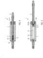
- Fig.1 shows a simplified schematic representation of individual components of various embodiments of a device 1 according to the invention for heating a foodstuff.
- the device 1 comprises a shaped tube 2.
- This can have a substantially cylindrical outer surface 3 and consist of an electrically non-conductive material, in particular completely or at least partially of a transparent material such as Plexiglas. It is also conceivable for the shaped tube 2 to be made of ceramic.
- the shaped tube 2 has an interior 4 which is delimited by an inner wall 5.
- a central section of the interior 4 is also cylindrical, but the interior 4 can also have any other cross-sectional shape.
- the interior 4 can have a diameter of, for example, 0.5 cm to 4 cm, but larger values are also conceivable.
- the interior 4 has a first opening 6 and a second opening 7 at its ends.
- a filling slide 8 is movable relative to the molding tube 2 and is intended to be inserted at least in sections into the interior 4 of the molding tube 2.
- an outer contour of the filling slide 8 is designed to be congruent to the cross section of the interior 4 of the shaped tube, but is dimensioned minimally smaller than the cross section of the interior 4 in order to seal the interior 4 at the first opening 6, but still allow it to be moved comparatively easily in the interior 4 .
- the outer contour 9 of the filling slide 8 can therefore be circular.
- the filling slide 8 is designed as a filling tube, ie with a line 10 in its interior, which is connected to a distal (in Fig. 1 : left) end is closed by a filling valve 11, designed here as a cone valve.
- the filling slide 8 is connected to a reservoir 13, in which the food 14 to be heated is held, via a schematically indicated, for example flexible, supply line 12.
- the food 14 can be pasty, for example a dough or meatloaf.
- the food 14 can be conveyed via the supply line to the filling slide 8 using a suitable conveying means such as a pump (not shown).
- the filling slide 8 has a first cap 15.
- the cap 15 has a concave surface 16 facing the interior 4.
- the opening of the filling valve 11 is located approximately in the center of the concave surface 16.
- the shaped tube 2 has a step 17.
- a second cap 18 with a cap body 19 can be inserted into the step 17.
- the cap body 19 comprises a flange 20 which can be inserted into the step 17.
- the second cap 18 has a concave Surface 21 which faces the interior 4 of the forming tube 2 or the concave surface 16 of the filling slide 8.
- a valve element 23 is movably mounted in the cap body 19, forming an air valve 22 on the second cap 18.
- the air valve 22 is designed as a cone valve, the opening of which is located approximately in the center of the concave surface 21 of the second cap 18.
- An air line 24 connects the air valve 22 to a vacuum source 25, for example a vacuum pump.
- a collet 26 is arranged in the molding tube 2.
- the collet 26 has two clamping jaws 26a, 26b, which can be moved relative to one another between an open position and a clamping position. In the open position, the distance between the clamping jaws 26a, 26b is large enough to allow the filling slide 8 to pass between them.
- the device 1 has a heating device 27, which can be connected to a controller 28 of the device 1.
- the heating device 27 serves to provide energy for heating a food 14 located in the molding tube 2.
- the heating device 27 can be configured in different ways.
- it can be a microwave generator that generates microwave radiation 29 and directs it onto the food 14 located in the mold tube 2.
- the heating device can be or comprise a liquid bath in which the shaped tube 2 is embedded to absorb heat, and/or the heating device 27 can comprise electrical resistance heating elements which rest on the shaped tube 2 or can be embedded in the wall of the shaped tube 2.
- the heating device 27 can have or include a power source and - as explained in detail below - be configured for ohmic heating of a food located in the molding tube 2.
- the first cap 15 and the second cap 18 are each designed as first and second electrodes, i.e. made of electrically conductive material.
- the concave surface 16, 21 of the first and second electrodes 15, 18 can be provided with a coating made of silver, for example.
- the collet chuck 26 and the filling slide 8 are preferably also electrically conductive or made of an electrically conductive material, and power lines 30 lead from the heating device 27 to the second cap 18 or to the collet chuck 26.
- the device has a substantially rod-shaped ejector 31.
- This comprises an annular cleaning lip 32 made of flexible material.
- the cleaning lip 32 is dimensioned such that it enables mechanical cleaning of the inner wall 5 of the interior 4 of the molding tube 2 when the ejector 31 is pushed from right to left through the interior 4.
- Fig.2 For the sake of clarity, some components of the device 1 are no longer shown.
- the device 1 is in a first state.
- the filling slide 8 is guided as far as possible into the interior 4 of the forming tube 2.
- the collet 26 is in its open position.
- the second cap 18 is inserted into the step 17 at the second opening 7 of the forming tube 2.
- the first and second caps 15, 18 touch each other or are only a minimal distance apart.
- the concave surfaces 16, 21 of the two caps 15, 18 form a cavity 33 between the two caps 15, 18.
- the air valve 22 is in its open position, in which the valve element 23 is retracted to the left. Via the air line 24, the vacuum source 25 ensures that the cavity 33 is evacuated via the air valve 22.
- the air pressure in the cavity 33 can be reduced to a value of less than 500 mbar, preferably less than 200 mbar or even less than 100 mbar.
- Fig.3 shows the device 1 in a second state.
- the air valve 22 has been closed by moving the valve element 23 of the air valve 22, which is designed as a cone valve, to the right into its valve seat. This completes the evacuation of the cavity 33.
- This offers the advantage that the subsequent filling of the cavity 33 with a food 14 is counteracted by considerably less resistance; in addition, the risk of air contained in the cavity 33 being stored in the food 14 when the cavity is filled and forming undesirable bubbles there is reduced, which could burst when the food is heated or cooked and destroy the food.
- Fig. 4 shows the device 1 in a third state, namely at the start of filling the cavity 33 with food.
- the filling valve 11 is open.
- the (usually pasty) food 14 is guided from the reservoir 13 to the filling slide 8 via the supply line 12.
- the food 14 is filled into the cavity 33 under a very high pressure of, for example, 10 bar to 25 bar.
- the internal pressure of the food 14 within the cavity 33 acts as a drive for the filling slide 8, which moves the filling slide 8 to the right, since the first cap 18 is fixed relative to the molding tube 2 more firmly than the filling slide 8.
- a (small) distance has already formed between the first cap 15 and the second cap 18.
- the cavity 33 is no longer empty from the start of filling with food 14; it can even (and usually will) be completely filled with the food 14.
- the term “ cavity” 33 is used in the sense of the invention even if the space between the two caps 15, 18 is completely or partially filled.
- Fig.5 shows the device 1 in a fourth state, in which the filling of the cavity 33 with the food 14 is completed.
- the entire space between the first cap 15 and the second cap 18 is filled with the food 14.
- the filling valve 11 on the filling slide 8 is shut off.
- the clamping jaws 26a, 26b of the collet 26 are brought into the closed position in which they clamp the filling slide 8 between them and thus fix it in place relative to the molding tube 2.
- the heating of the food 14 can be carried out.
- the heating device 27 serves to supply heat to the portion of the food 14 contained in the cavity 33. This can be done by means of heat conduction via the molding tube 2, by supplying electromagnetic radiation, for example microwave radiation 29, or by ohmic heating by applying an electrical voltage between the first and second caps 15, 18 designed as electrodes via the collet 26 and the electrically conductive filling slide 8. A current flows through the food 14, which is also electrically conductive, and is converted into heat by the electrical resistance of the food 14, which heats the food 14 at least locally, preferably completely and homogeneously.
- Heating is to be understood as meaning that the temperature of the food rises, for example by at least 5°C, whereby the food 14 can optionally also be cooked.
- the electrical voltage between the two caps 15, 18 designed as electrodes can be, for example, between 150V and 650V and can be applied for a duration of, for example, 5s to 45s.
- Fig.6 shows the device in a fifth state.
- the collet 26 has been brought into its open position.
- the filling slide 8 has been moved to the right and completely removed from the forming tube 2.
- the assembly with the second cap 18 has also been moved out of the step 17 and completely removed from the forming tube 2.
- the heated food 14 is still located in the interior 4 of the forming tube 2.
- the shape of the ends of the food 14 is predetermined by the concave surfaces 16, 21 of the caps 15, 18 or according to the shape of these surfaces 16, 21.
- Fig. 7 shows the device 1 in a sixth state.
- the forming tube 2 has been moved out of alignment 34 between the filling slide 8 and the second cap 18.
- the shaped tube 2 is mounted in a guide 35 and is offset along the guide relative to the filling slide 8.
- the shaped tube 2 (or a plurality of such shaped tubes 2) is arranged on a support 36, for example a rotatable drum 36, and was removed from alignment 34 by means of this.
- the mold slide 8 and the assembly with the second cap 18 are moved while the mold tube 2 remains stationary.
- the interior 4 of the shaped tube 2 is now aligned with the ejector 31. This is inserted through the first opening 6 into the interior of the shaped tube 2.
- the cleaning lip 32 strokes along the inner wall 5 of the interior 4 and in this way cleans the inner wall 5.
- the second opening 7 is free or open.
- Fig. 8 shows the device 1 in a seventh state. Based on the condition in Fig. 7 the ejector 31 has been moved so far through the interior 4 of the shaped tube 2 that the cleaning lip 32 has emerged from the second opening 7 of the shaped tube 2 at the distal end of the ejector 31. In this way, the heated (or cooked) food 14 is ejected or discharged from the forming tube 2. As a result, the device 1 or the method produces a heated, pre-cooked or even cooked food such as a sausage, for example a hot dog sausage, or a stick (pre-)baked from dough.
- the device 1 can be returned to the Fig.2 return to the first state shown; the cycle begins again.
- Fig. 9 shows a further exemplary embodiment of a device 1 according to the invention.
- the cap body 19 with the second cap 18 is here stationary relative to the shaped tube 2.
- the cap body 19 can be firmly mounted on the shaped tube 2 for this purpose.
- the air valve 22 can be connected via the air line 24 not only to a vacuum source 25, but also selectively to a compressed air source 37.
- element 37 can simply be a connection to the ambient air (normal pressure).
- a directional control valve 38 can be controlled by the controller 28 and ensures that the air valve 22 is always fluidly connected either to the vacuum source 25 or to the compressed air source 37.
- Fig. 9 shows the device 1 in a state in which the heating of the food 14 has been completed and the filling slide 8 has been completely removed from the forming tube 2.
- Fig. 10 shows the exemplary embodiment Fig. 9 in a second state. Starting from the in Fig. 9 In the state shown, the air valve 22 has been opened and connected via the directional control valve 38 to the compressed air source 37 or the ambient air under normal pressure. Air or compressed air is therefore passed into the cavity 33 via the air valve 22 in the second cap 18.
- the compressed air ensures that the heated food 14 is discharged or ejected to the right out of the forming tube 2.
- the second cap 18 or its cap body 19 serve as a counter bearing since they are connected in a stationary manner to the shaped tube 2.
- the compressed air can at the same time have a cleaning effect on the inner wall 5 of the interior 4.
- the device according to the invention and the method according to the invention can be modified in many ways.
- the compressed air source 37 and the directional control valve 38 can be dispensed with if ventilating the cavity 33 via the air valve 22 with normal pressure is sufficient to ventilate the food 14 - as in Fig. 11 shown - from the molding tube 2.
- the air valve 22 can, but does not have to, be formed in one piece with the cap body 19.
- it could also be arranged adjacent to the cap 18 in the wall of the molding tube 2.
- objects in the cavity 33 could also be sterilized.
Landscapes
- Health & Medical Sciences (AREA)
- Nutrition Science (AREA)
- Life Sciences & Earth Sciences (AREA)
- Chemical & Material Sciences (AREA)
- Engineering & Computer Science (AREA)
- Food Science & Technology (AREA)
- Polymers & Plastics (AREA)
- General Preparation And Processing Of Foods (AREA)
- Commercial Cooking Devices (AREA)
Description
Die Erfindung betrifft eine Vorrichtung und ein Verfahren zum Erwärmen eines Lebensmittels, vorzugsweise zum zumindest teilweisen Garen des Lebensmittels.The invention relates to a device and a method for heating a food, preferably for at least partially cooking the food.
Vorrichtungen zum Ohmschen Erwärmen oder Kochen von Lebensmitteln, indem ein Strom durch das elektrisch leitfähige Lebensmittel geleitet wird, sind bereits bekannt, beispielsweise aus der
Herkömmliche Vorrichtungen und Verfahren haben zwar den Vorteil, dass das Lebensmittel relativ gleichmäßig und homogen erwärmt oder gegart werden kann, ohne dass es lokal überhitzt oder verbrennt. Gleichzeitig ist die Leistungsfähigkeit herkömmlicher Vorrichtungen und Verfahren jedoch begrenzt.Conventional devices and methods have the advantage that the food can be heated or cooked relatively evenly and homogeneously without it locally overheating or burning. At the same time, however, the performance of conventional devices and methods is limited.
Die Aufgabe der Erfindung besteht darin, eine Vorrichtung und ein Verfahren zum Erwärmen von Lebensmitteln zur Verfügung zu stellen, die im Vergleich zu herkömmlichen Vorrichtungen und Verfahren eine höhere Produktivität erlauben.The object of the invention is to provide a device and a method for heating food which allow higher productivity compared to conventional devices and methods.
Diese Aufgabe wird gelöst durch eine Vorrichtung mit den Merkmalen des Anspruchs 1 oder durch ein Verfahren zum Erwärmen eines Lebensmittels mit den Merkmalen des Anspruchs 9. Vorteilhafte Weiterbildungen der Erfindung sind in den abhängigen Ansprüchen angegeben.This object is achieved by a device having the features of claim 1 or by a method for heating a foodstuff having the features of claim 9. Advantageous developments of the invention are specified in the dependent claims.
Die erfindungsgemäße Vorrichtung und das erfindungsgemäße Verfahren eignen sich besonders gut für das Erwärmen, ggf. bis hin zu einem Garen oder Kochen, von pastösen Lebensmitteln wie beispielsweise Fleischbrät oder auch Teigwaren. Bei einer Verwendung von Fleischbrät als Lebensmittel können bei der Behandlung durch die Vorrichtung oder das Verfahren der Erfindung vorgegarte oder bereits fertig gegarte Wurstwaren erzeugt werden, beispielsweise Hotdog-Würstchen oder sogenannte Wiener Würstchen.The device according to the invention and the method according to the invention are particularly suitable for heating, possibly even cooking, pasty foods such as meatloaf or pasta. When meat sausages are used as food, pre-cooked or already fully cooked sausage products can be produced during treatment by the device or method of the invention, for example hot dog sausages or so-called Vienna sausages.
Das in der Vorrichtung verwendete Formrohr muss nicht notwendigerweise eine Kreiszylinderform aufweisen. Es könnte zwar einen kreisrunden Innenquerschnitt aufweisen, dieser könnte jedoch auch andere Formen haben, beispielsweise oval, quadratisch, polygonal etc. Das Formrohr besteht aus einem elektrisch nicht oder fast nicht leitfähigen Material, das außerdem genügend hitzebeständig sein sollte, d.h. Temperaturen von beispielsweise 80°C, vorzugsweise 100°C oder noch weiter bevorzugt mindestens 120°C problemlos standhalten sollte. Das Formrohr sollte außerdem mechanisch genügend stark sein, um sich auch bei vergleichsweise hohen Innendrücken nicht zu verformen. Erreicht werden kann dies durch geeignete Wandstärken von beispielsweise mindestens 0,5 cm, bevorzugt mindestens 1 cm oder weiter bevorzugt mindestens 1,5 cm.The shaped tube used in the device does not necessarily have to have a circular cylindrical shape. Although it could have a circular internal cross-section, this could also have other shapes, for example oval, square, polygonal, etc. The shaped tube consists of an electrically non-conductive or almost non-conductive material, which should also be sufficiently heat-resistant, ie temperatures of, for example, 80° C, preferably 100 ° C or even more preferably at least 120 ° C should easily withstand. The shaped tube should also be mechanically strong enough not to deform even at comparatively high internal pressures. This can be achieved through suitable wall thicknesses of, for example, at least 0.5 cm, preferably at least 1 cm or more preferably at least 1.5 cm.
Das Formrohr kann abschnittsweise (beispielsweise als Fenster) oder insgesamt einen transparenten Werkstoff aufweisen. Dies hat den Vorteil, dass die Vorgänge im Inneren, insbesondere eine optische Änderung des Lebensmittels beim Erwärmen, visuell oder mittels eines Vision-Systems erkannt oder überwacht werden können. Zusätzlich oder alternativ zu einem transparenten Material kann das Formrohr wenigstens abschnittsweise ein Keramik-Material aufweisen. Günstig ist es, wenn das Material des Formrohrs verschleißfest ist und/oder eine Antihaftwirkung bezüglich des Lebensmittels hat.The molded tube can have a transparent material in sections (for example as a window) or in its entirety. This has the advantage that the processes inside, in particular an optical change in the food when heated, can be recognized or monitored visually or using a vision system. In addition to or as an alternative to a transparent material, the molded tube can have a ceramic material at least in sections. It is advantageous if the material of the molded tube is wear-resistant and/or has a non-stick effect on the food.
Im Formrohr ist ein Füllschieber beweglich geführt. Dieser Füllschieber ist idealerweise so geformt, dass sein Außenquerschnitt kongruent aber etwas kleiner ist als der Innenquerschnitt des Formrohrs. Der Füllschieber kann hohl sein und auf diese Weise Teil einer Leitung zum Zuführen des Lebensmittels in einen Hohlraum sein. In dieser Form kann der Füllschieber als Füllrohr bezeichnet werden.A filling slide is movably guided in the forming tube. This filling slide is ideally shaped so that its external cross-section is congruent but slightly smaller than the internal cross-section of the forming tube. The filling slide can be hollow and thus be part of a line for feeding the food into a hollow space. In this form, the filling slide can be referred to as a filling tube.
In der Vorrichtung sind zwei Kappen vorgesehen, zwischen denen das Lebensmittel in einem Hohlraum aufnehmbar ist, nämlich eine erste, dem Füllschieber zugeordnete Kappe und eine zweite, dem Füllschieber gegenüberliegende Kappe. Beide Kappen haben einander zugewandte, jeweils konkave Oberflächen, zwischen denen sie den Hohlraum zur Aufnahme des Lebensmittels begrenzen. Dabei bedeutet "konkave Oberfläche", dass zumindest ein Teil der dem Hohlraum zugewandten Oberfläche der jeweiligen Kappe konkav ist, wobei allerdings auch die gesamte, dem Hohlraum zugewandte Oberfläche einer Kappe konkav sein kann. Solche konkav ausgebildeten Oberflächen haben sich als günstig erwiesen hinsichtlich der späteren Form des fertig behandelten Lebensmittels und hinsichtlich des Wärmeeintrags in das Lebensmittel.The device has two caps between which the food can be received in a cavity, namely a first cap associated with the filling slide and a second cap opposite the filling slide. Both caps have concave surfaces facing each other, between which they delimit the cavity for receiving the food. "Concave surface" means that at least part of the surface of the respective cap facing the cavity is concave, although the entire surface of a cap facing the cavity can also be concave. Such concave surfaces have proven to be advantageous with regard to the subsequent shape of the finished processed food and with regard to the heat input into the food.
Erfindungsgemäß weist die Vorrichtung an der zweiten Kappe ein Luftventil auf. Wie aus der nachfolgenden Erläuterung hervorgehen wird, hat sich diese Maßnahme als äußerst vorteilhaft im Hinblick auf eine besonders hohe Produktivität der erfindungsgemäßen Vorrichtung erwiesen. "Luftventil" bedeutet dabei, dass Luft durch das Ventil hindurchführbar ist. "An der zweiten Kappe" bedeutet im Kontext der Erfindung, dass das Luftventil in, an oder neben der zweiten Kappe angeordnet sein kann, auf jeden Fall jedoch auf der dem Füllschieber gegenüberliegenden Seite des Hohlraums.According to the invention, the device has an air valve on the second cap. As will become clear from the following explanation, this measure has proven to be extremely advantageous with regard to a particularly high productivity of the device according to the invention. “Air valve” means that air can be passed through the valve. “On the second cap” in the context of the invention means that the air valve can be arranged in, on or next to the second cap, but in any case on the side of the cavity opposite the filling slide.
Bevorzugt ist über das Luftventil der zwischen den Kappen gebildete Hohlraum evakuierbar, d.h. im Hohlraum ist ein Unterdruck im Vergleich zum Normaldruck erzeugbar. Zu diesem Zweck kann die Vorrichtung über eine Vakuumquelle oder eine Vakuumpumpe verfügen oder mit einer solchen verbunden werden, um das Evakuieren über das Luftventil bewirken zu können. Die Vorrichtung kann dazu konfiguriert sein, im Hohlraum einen Unterdruck von beispielsweise 500 mbar, bevorzugt von 200 mbar oder sogar von 100 mbar oder weniger zu erzeugen. Bevor das Lebensmittel über den Füllschieber in den Hohlraum eingeführt wird, wird das Evakuieren des Hohlraums über das Luftventil zumindest teilweise, vorzugsweise jedoch bereits vollständig abgeschlossen. Dies bietet zum Einen den Vorteil, dass das Füllen des Hohlraums mit dem Lebemsmittel schneller erfolgen kann, als wenn das Lebensmittel gegen einen im Hohlraum herrschenden Normaldruck eingefüllt werden müsste. Zum Zweiten verringert sich durch den niedrigeren Gegendruck im Hohlraum der Energiebedarf für das Einfüllen, und zum Dritten wird die Gefahr einer unerwünschten Einlagerung von Luft in das Lebensmittel beim Einfüllen des Lebensmittels verringert.The cavity formed between the caps can preferably be evacuated via the air valve, ie a negative pressure can be generated in the cavity compared to the normal pressure. For this purpose, the device can have or be connected to a vacuum source or a vacuum pump in order to be able to effect evacuation via the air valve. The device can be configured to generate a negative pressure of, for example, 500 mbar, preferably 200 mbar or even 100 mbar or less in the cavity. Before the food is introduced into the cavity via the filling slide, the evacuation of the cavity is at least partially, but preferably completely, completed via the air valve. On the one hand, this offers the advantage that the cavity can be filled with the food more quickly than if the food had to be filled against a normal pressure prevailing in the cavity. Secondly, the lower back pressure in the cavity reduces the energy requirement for filling, and thirdly, the risk of undesired air being incorporated into the food when filling the food is reduced.
Die Vorrichtung kann dazu konfiguriert sein, zwischen der ersten und der zweiten Kappe eine elektrische Spannung anzulegen, die zu einem Stromfluss durch das zwischen den Kappen befindliche Lebensmittel führt. Zu diesem Zweck sind die beiden Kappen vorzugsweise als Elektroden ausgebildet und verfügt die Vorrichtung als Heizeinrichtung über eine eigene Stromquelle oder über eine Verbindung zu einer externen Stromquelle. Die Vorrichtung kann eine Steuerung aufweisen, die dazu konfiguriert ist, die elektrische Spannung lediglich zu bestimmten Zeitpunkten bzw. über bestimmte Zeitintervalle zwischen den beiden Elektroden anzulegen. Es versteht sich, dass das Lebensmittel elektrisch leitfähig sein muss, um bei Anlegen eines Stroms erwärmt werden zu können.The device can be configured to apply an electrical voltage between the first and second caps, which leads to a current flow through the food located between the caps. For this purpose, the two caps are preferably designed as electrodes and the device has its own power source as a heating device or a connection to an external power source. The device can have a controller that is configured to apply the electrical voltage between the two electrodes only at certain times or over certain time intervals. It goes without saying that the food must be electrically conductive in order to be able to be heated when a current is applied.
Für das Material der Elektroden hat sich eine Kupferlegierung als besonders effektiv erwiesen. Optional kann zumindest die dem Hohlraum zugewandte Oberfläche der Elektroden zur Verbesserung der Leitfähigkeit und zum Korrosionsschutz mit einer Silberschicht überzogen sein; die Silber-Beschichtung hat vorzugsweise eine Stärke zwischen 5 Mikrometern und 20 Mikrometern.A copper alloy has proven to be particularly effective for the material of the electrodes. Optionally, at least the surface of the electrodes facing the cavity can be coated with a silver layer to improve conductivity and to protect against corrosion; the silver coating preferably has a thickness between 5 micrometers and 20 micrometers.
Alternativ oder zusätzlich zur Ohmschen Erwärmung kann die Vorrichtung dazu konfiguriert sein, das Lebensmittel mittels elektromagnetischer Strahlung zu erwärmen oder ggf. zu garen. In dieser Ausführungsform kann als Heizeinrichtung der Vorrichtung z.B. ein Mikrowellen-Erzeuger vorgesehen sein und das im Hohlraum befindliche Lebensmittel den vom Mikrowellen-Erzeuger generierten Mikrowellen aussetzbar sein.Alternatively or in addition to ohmic heating, the device can be configured to heat or, if necessary, cook the food using electromagnetic radiation. In this embodiment, a microwave generator, for example, can be provided as the heating device of the device and the food in the cavity can be exposed to the microwaves generated by the microwave generator.
Zusätzlich oder alternativ kann die Vorrichtung dazu konfiguriert sein, das Lebensmittel mittels Wärmeleitung zu erwärmen. In dieser Konfiguration kann die Heizeinrichtung dazu vorgesehen sein, zunächst das Formrohr zu erwärmen, beispielsweise indem die Heizeinrichtung in das Formrohr eingebettete Heizkartuschen oder ein das Formrohr aufnehmendes, erwärmtes Flüssigkeits-Bad aufweist, bevor das Formrohr die Wärme an das im Hohlraum befindliche Lebensmittel weitergibt.Additionally or alternatively, the device can be configured to heat the food using heat conduction. In this configuration, the heating device can be provided to first heat the shaped tube, for example by the heating device having heating cartridges embedded in the shaped tube or a heated liquid bath that accommodates the shaped tube, before the shaped tube passes on the heat to the food located in the cavity.
Denkbar ist es, dass über das Luftventil dem zwischen den Kappen gebildeten Hohlraum Druckluft zuführbar ist. Zu diesem Zweck kann die Vorrichtung mit einer Druckluftquelle ausgestattet oder verbindbar sein. Die Zufuhr von Druckluft in den Hohlraum kann das Ausschleusen oder Ausstoßen des fertig behandelten Lebensmittels auf der dem Luftventil gegenüberliegenden Seite unterstützen und erheblich vereinfachen oder auch zum Reinigen des Formrohrs eingesetzt werden.It is conceivable that compressed air can be supplied to the cavity formed between the caps via the air valve. For this purpose, the device can be equipped or connectable to a source of compressed air. The supply of compressed air into the cavity can support and considerably simplify the removal or ejection of the finished food on the side opposite the air valve or can also be used to clean the molding tube.
Besonders bevorzugt ist eine Ausführungsform, bei der über das Luftventil sowohl der Hohlraum zwischen den Kappen evakuierbar als auch diesem Hohlraum Luft unter Normaldruck zum Belüften oder Druckluft zuführbar ist. In dieser Ausführungsform bekommt das Luftventil somit eine Doppelfunktion. Wenn wahlweise Luft unter Normaldruck oder Druckluft zuführbar sind, bekommt das Luftventil sogar eine Dreifachfunktion. Bereits ein Belüften kann den Vorteil bieten, Verformungen des Lebensmittels beim Rücksetzen des Füllschiebers zu vermeiden.A particularly preferred embodiment is one in which the cavity between the caps can be evacuated via the air valve and air under normal pressure for ventilation or compressed air can be supplied to this cavity. In this embodiment, the air valve thus has a dual function. If either air under normal pressure or compressed air can be supplied, the air valve even has a triple function. Ventilation alone can offer the advantage of preventing the food from deforming when the filling slide is reset.
In konstruktiver Hinsicht hat es sich als günstig erwiesen, das Luftventil als Kegelventil auszubilden. Ein solches Kegelventil hält den erforderlichen Drücken stand, baut klein und kann somit bei Bedarf zumindest teilweise in das Formrohr eingebaut werden. Es ermöglicht außerdem eine präzise Ansteuerung und ein sicheres Verschließen.From a design point of view, it has proven to be advantageous to design the air valve as a cone valve. Such a cone valve can withstand the required pressures, is small and can therefore be at least partially installed in the shaped pipe if necessary. It also enables precise control and secure closure.
Besonders einfach wird die Konstruktion der Vorrichtung, wenn das Luftventil einstückig mit der zweiten Kappe ausgebildet ist. Damit ist gemeint, dass der Ventilsitz (selbstverständlich aber nicht der relativ dazu bewegbare Ventilkörper) einstückig mit der zweiten Kappe geformt ist. Auf diese Weise verringert sich die Zahl der Bauteile der Vorrichtung.The construction of the device is particularly simple if the air valve is formed in one piece with the second cap. This means that the valve seat (but of course not the valve body that can move relative to it) is formed in one piece with the second cap. In this way, the number of components of the device is reduced.
Als zweckmäßig hat es sich erwiesen, wenn die zweite Kappe ortsfest bezüglich des Formrohrs angeordnet ist. Auf diese Weise kann die zweite Kappe besonders fest gesichert sein; sie kann insbesondere beim Ausstoßen des behandelten Lebensmittels als Gegenlager für den Ausstoß-Druck dienen.It has proven to be useful if the second cap is arranged in a fixed position relative to the forming tube. In this way, the second cap can be secured particularly firmly; it can serve as a counter bearing for the ejection pressure, particularly when the treated food is ejected.
In einer alternativen Ausführungsform ist die zweite Kappe relativ zum Formrohr beweglich gelagert. Dies erlaubt es, die zweite Kappe (die optional als zweite Elektrode ausgebildet sein kann) relativ zum Formrohr zu verlagern, um eine Öffnung des Hohlraums zu erzeugen, durch die das Lebensmittel nach seiner Erwärmung ausgestoßen werden kann.In an alternative embodiment, the second cap is mounted movably relative to the shaped tube. This allows the second cap (which can optionally be designed as a second electrode) to be displaced relative to the forming tube to create an opening in the cavity through which the food can be ejected after it has been heated.
Vorzugsweise ist der Füllschieber vollständig aus dem Formrohr herausführbar. Dadurch wird es möglich, das behandelte Lebensmittel durch dieselbe Öffnung auszuschleusen, durch die der Füllschieber in das Formrohr hineinführbar ist. Zweckmäßig ist es dabei, wenn der Füllschieber auch in einer vollständig aus dem Formrohr herausgeführten Stellung geeignet geführt oder gelagert ist, so dass er eine axiale Ausrichtung relativ zum Formrohr beibehält oder gesichert wieder einnehmen kann, um nach dem Ausschleusen des Lebensmittels vergleichsweise schnell und sicher wieder in das Formrohr eingebracht werden zu können.Preferably, the filling slide can be completely removed from the molding tube. This makes it possible to discharge the treated food through the same opening through which the filling slide can be inserted into the forming tube. It is expedient if the filling slide is also suitably guided or stored in a position that is completely led out of the shaped tube, so that it maintains an axial alignment relative to the shaped tube or can safely assume it again in order to be able to return comparatively quickly and safely after the food has been discharged to be able to be introduced into the shaped tube.
In einer vorteilhaften Ausführungsform umfasst der Füllschieber ein absperrbares Einfüllventil. Dieses wird nur so lange geöffnet, wie das Lebensmittel durch den Füllschieber in den Hohlraum eingefüllt wird. Das Absperren kann sicherstellen, dass stets ein vorbestimmtes Maximalvolumen des Lebensmittels in den Hohlraum eingefüllt wird.In an advantageous embodiment, the filling slide includes a lockable filling valve. This is only opened as long as the food is filled into the cavity through the filling slide. Shutting off can ensure that a predetermined maximum volume of food is always filled into the cavity.
Denkbar ist es, dass der Füllschieber als hohles Füllrohr konfiguriert ist. Alternativ könnte der Füllschieber auch einen im Wesentlichen U-förmigen Querschnitt mit einer Einfüllnut auf seiner Außenseite aufweisen. Die Konfiguration als hohles Füllrohr hat jedoch den Vorteil, leichter absperrbar zu sein.It is conceivable that the filling slide is configured as a hollow filling tube. Alternatively, the filling slide could also have a substantially U-shaped cross section with a filling groove on its outside. However, the configuration as a hollow filling pipe has the advantage of being easier to shut off.
Die Vorrichtung kann eine Spannzange aufweisen, die beispielsweise am Formrohr montiert sein kann und in der der Füllschieber temporär fixierbar oder festklemmbar ist. Zu diesem Zweck kann die Spannzange zwei relativ zueinander bewegliche Spannbacken aufweisen. Dies bietet den Vorteil, den Füllschieber während des Erwärmens des Lebensmittels zumindest temporär relativ zum Formrohr ortsfest fixieren zu können. Dies verhindert, dass der Füllschieber durch den Innendruck des Lebensmittels zu früh nach außen bewegt wird und das Lebensmittel dabei zerstört wird.The device can have a collet, which can be mounted, for example, on the shaped tube and in which the filling slide can be temporarily fixed or clamped. For this purpose, the collet chuck can have two clamping jaws that are movable relative to one another. This offers the advantage of being able to at least temporarily fix the filling slide in a stationary manner relative to the molding tube while the food is being heated. This prevents the filling slide from being moved outwards too early due to the internal pressure of the food and the food being destroyed in the process.
Besonders günstig ist es, wenn die Spannzange elektrisch leitfähig ausgebildet ist. Dies ermöglicht es, beispielsweise einer am Füllschieber vorgesehenen, als Elektrode ausgebildeten ersten Kappe einen Strom zuzuleiten, wenn das Lebensmittel durch Ohmsche Erwärmung erhitzt werden soll. Die Spannzange kann der lokalen Übertragung von Strom und Wärme (Heizung in Spannbacken integriert) an die Kappe (Elektrode) des Füllschiebers dienen. Die Positionierung und das Halten des Füllschiebers kann durch einen zuschaltbaren externen mechanischen Anschlag erfolgen oder unterstützt werden.It is particularly advantageous if the collet is designed to be electrically conductive. This makes it possible, for example, to supply a current to a first cap designed as an electrode on the filling slide if the food is to be heated by ohmic heating. The collet can be used for the local transfer of current and heat (heating integrated in the clamping jaws) to the cap (electrode) of the filling slide. The positioning and holding of the filling slide can be carried out or supported by a switchable external mechanical stop.
Die Vorrichtung kann als weitere Komponente einen Auswerfer aufweisen. Dieser kann stabförmig ausgebildet sein. Der Auswerfer kann dazu dienen, das Lebensmittel aus dem Formrohr herauszuschieben, nachdem das Lebensmittel erwärmt wurde und sowohl die erste Kappe als auch die zweite Kappe aus dem Formrohr entfernt wurden. Der Auswerfer kann optional eine flexible Reinigungslippe aufweisen, um beim Auswerfen des Lebensmittels aus dem Formrohr die Innenwand des Formrohrs mechanisch zu reinigen.The device can have an ejector as a further component. This can be rod-shaped. The ejector can serve to push the food out of the forming tube after the food has been heated and both the first cap and the second cap have been removed from the forming tube. The ejector can optionally have a flexible cleaning lip in order to mechanically clean the inner wall of the forming tube when ejecting the food from the forming tube.
Im erfindungsgemäßen Verfahren zum Erwärmen, ggf. Garen oder Kochen, eines Lebensmittels wird das Lebensmittel über einen Füllschieber in einen Hohlraum in einem Formrohr eingefüllt und dann vollständig oder zumindest lokal erwärmt. Dieses Verfahren kann durchgeführt werden mit einer Vorrichtung in einer der vorstehend beschriebenen Varianten. Erfindungsgemäß ist vorgesehen, dass der Hohlraum vor dem Einfüllen des Lebensmittels in diesen Hohlraum über ein Luftventil evakuiert wird, d.h. dass ein Unterdruck im Vergleich zum Normaldruck im Hohlraum erzeugt wird. Dies erleichtert das Einfüllen des Lebensmittels und senkt wegen des geringeren Widerstands den Energiebedarf; gleichzeitig wird ein unerwünschtes Einlagern von Luft in das Lebensmittel und ggf. eine Dampfblasenbildung verhindert oder zumindest stark verringert.In the method according to the invention for heating, possibly cooking or boiling, a food, the food is filled into a cavity in a molding tube via a filling slide and then heated completely or at least locally. This method can be carried out with a device in one of the variants described above. According to the invention, the cavity is evacuated via an air valve before the food is filled into this cavity, i.e. a negative pressure is generated in the cavity compared to the normal pressure. This makes it easier to fill the food and reduces the energy requirement due to the lower resistance; at the same time, unwanted storage of Air in the food and possible formation of steam bubbles is prevented or at least greatly reduced.
Vorzugsweise wird der Füllschieber während des Befüllens des Hohlraums mit dem Lebensmittel innerhalb des Formrohrs verschoben. Dieses Verschieben erfolgt durch einen Fülldruck des den Hohlraum füllenden Lebensmittels, d.h. durch eine Art Rückstoßeffekt. Zur Vermeidung von Stick-Slip-Effekten kann die Bewegung des Füllschiebers über ein Drosselventil eingestellt werden. Der Vorteil des Verschiebens des Füllschiebers während des Befüllens des Hohlraums liegt darin, dass der Hohlraum zunächst vergleichsweise klein gehalten und auf diese Weise schnell evakuiert werden kann, was die Produktivität erhöht.Preferably, the filling slide is moved within the forming tube while the cavity is being filled with the food. This displacement is caused by a filling pressure of the food filling the cavity, i.e. by a kind of recoil effect. To avoid stick-slip effects, the movement of the filling slide can be adjusted using a throttle valve. The advantage of moving the filling slide while filling the cavity is that the cavity can initially be kept comparatively small and can be evacuated quickly in this way, which increases productivity.
Als zweckmäßig hat es sich erwiesen, wenn der Fülldruck des den Hohlraum füllenden Lebensmittels vergleichsweise hoch ist und mindestens 10 bar beträgt, vorzugsweise sogar mindestens 15 bar, weiter bevorzugt im Bereich von 15 bar bis 25 bar. Mit diesen Drücken kann sowohl ein schnelles Befüllen des Hohlraums als auch ein Herausschieben des Füllschiebers aus dem Formrohr bewirkt werden. In Ausführungsbeispielen ist dieses Herausschieben sogar möglich, ohne dass ein aktiver Antrieb zum Verschieben des Füllschiebers aus dem Formrohr heraus erforderlich wäre.It has proven to be useful if the filling pressure of the food filling the cavity is comparatively high and amounts to at least 10 bar, preferably even at least 15 bar, more preferably in the range from 15 bar to 25 bar. These pressures can be used to quickly fill the cavity and also push the filling slide out of the forming tube. In embodiments, this pushing out is even possible without an active drive being required to push the filling slide out of the forming tube.
Vorzugsweise ist der Füllschieber vollständig aus dem Formrohr herausbewegbar, damit das Lebensmittel aus dem Formrohr ausgeschleust werden kann. Damit gibt der Füllschieber gewissermaßen die Öffnung frei, durch die das Lebensmittel nach der Erwärmung ausgeschleust werden kann.Preferably, the filling slide can be moved completely out of the forming tube so that the food can be discharged from the forming tube. In this way, the filling slide releases the opening through which the food can be discharged after heating.
Ein Ausschleusen oder gewissermaßen Ausstoßen des Lebensmittels aus dem Formrohr kann durch Zufuhr von Druckluft in den Hohlraum erfolgen oder zumindest unterstützt werden. Das Vermeiden mechanischer Komponenten für ein Ausschleusen oder Ausstoßen mach die Vorrichtung weniger komplex und erleichtert deren Reinigung.The food can be removed or at least ejected from the molding tube by supplying compressed air into the cavity or at least supported. Avoiding mechanical components for ejection or ejection makes the device less complex and makes it easier to clean.
Besonders günstig ist es, wenn die zum Ausschleusen verwendete Druckluft dem Hohlraum über das zum Evakuieren verwendete Luftventil zugeführt wird. Dieses erhält damit eine Doppelfunktion sowohl zum Evakuieren als auch zum Unterstützen des Ausschleusens des Lebensmittels aus dem Hohlraum.It is particularly advantageous if the compressed air used for ejection is supplied to the cavity via the air valve used for evacuation. This gives the valve a dual function for both evacuation and for supporting the ejection of the food from the cavity.
In einer Ausführungsform kann eine Spannzange vorgesehen sein, mittels derer der Füllschieber in einer bestimmten Stellung während des Erwärmens des Lebensmittels zumindest temporär fixiert wird. Die Spannzange kann optional elektrisch leitfähig sein und auf diese Weise zum Zuführen eines elektrischen Stroms zum und durch das Lebensmittel eingesetzt werden, um dieses mittels Ohmscher Erwärmung zu erhitzen.In one embodiment, a collet chuck can be provided, by means of which the filling slide is at least temporarily fixed in a certain position while the food is being heated. The collet can optionally be electrically conductive and in this way can be used to supply an electrical current to and through the food in order to heat it using ohmic heating.
In einer Variante des Verfahrens wird ein beispielsweise stabförmiger Auswerfer eingesetzt, um das erwärmte Lebensmittel mechanisch aus dem Formrohr herauszuschieben. In diesem Fall ist es sinnvoll, wenn vor dem Ausschieben die beiden Kappen aus dem Formrohr entfernt werden. Der Auswerfer kann optional eine flexible Reinigungslippe aufweisen, um die Innenwände des Formrohrs beim Ausschieben des Lebensmittels mechanisch zu reinigen.In a variant of the method, a rod-shaped ejector, for example, is used to mechanically push the heated food out of the forming tube. In this In this case, it makes sense if the two caps are removed from the shaped tube before pushing it out. The ejector can optionally have a flexible cleaning lip in order to mechanically clean the inner walls of the forming tube when the food is pushed out.
Wie bereits einleitend ausgeführt, kann es sich beim Lebensmittel beispielsweise um eine pastöse Masse oder ein sogenanntes Brät handeln, beispielsweise um einen Teig oder um ein Fleischbrät.As already stated in the introduction, the food can be, for example, a pasty mass or a so-called sausage meat, for example a dough or a meatloaf.
Die bei der Option mit dem Ohmschen Erwärmen in der erfindungsgemäßen Vorrichtung und im erfindungsgemäßen Verfahren eingesetzten elektrischen Spannungen zwischen den beiden Elektroden liegen vorzugsweise im Bereich von 150V bis 650V. Die Stromstärke während der Behandlung eines Lebensmittels erreicht Werte von z.B. 1 bis 5A; die Leistung während des Erwärmens kann bei 0,5 bis 2,5 kW liegen, bevorzugt bei 1 bis 1,5 kW. Als Dauer für die Behandlung eines Lebensmittels durch Ohmsche Erwärmung haben sich Zeiträume von beispielsweise 10s bis 45s als günstig erwiesen. Welche Werte jeweils optimal sind, hängt beispielsweise von der Art des Lebensmittels und ggf. von dessen Konsistenz und/oder Feuchtigkeitsgrad ab.The electrical voltages used between the two electrodes in the option with ohmic heating in the device according to the invention and in the method according to the invention are preferably in the range from 150V to 650V. The current intensity during the treatment of a food reaches values of e.g. 1 to 5A; the power during heating can be 0.5 to 2.5 kW, preferably 1 to 1.5 kW. Periods of, for example, 10s to 45s have proven to be favorable as a duration for the treatment of a food by ohmic heating. Which values are optimal depends, for example, on the type of food and, if applicable, its consistency and/or degree of moisture.
An dieser Stelle sei angemerkt, dass alle im Zusammenhang mit der Vorrichtung beschriebenen Merkmale auch für das erfindungsgemäße Verfahren und dessen Varianten gelten, ebenso umgekehrt die im Zusammenhang mit dem Verfahren beschriebenen Merkmale auch auf die Vorrichtung anwendbar sind.At this point it should be noted that all features described in connection with the device also apply to the method according to the invention and its variants, and conversely the features described in connection with the method are also applicable to the device.
Im Folgenden werden vorteilhafte Ausführungsbeispiele der Erfindung anhand einer Zeichnung näher dargestellt. Im Einzelnen zeigen:
-
Fig. 1 eine schematische Darstellung wichtiger Komponenten eines ersten Ausführungsbeispiels der erfindungsgemäßen Vorrichtung, -
Fig. 2 das Ausführungsbeispiel vonFig. 1 in einem ersten Zustand, -
Fig. 3 das Ausführungsbeispiel vonFig. 1 in einem zweiten Zustand, -
Fig. 4 das Ausführungsbeispiel vonFig. 1 in einem dritten Zustand, -
Fig. 5 das Ausführungsbeispiel vonFig. 1 in einem vierten Zustand, -
Fig. 6 das Ausführungsbeispiel vonFig. 1 in einem fünften Zustand, -
Fig. 7 das Ausführungsbeispiel vonFig. 1 in einem sechsten Zustand, -
Fig. 8 das Ausführungsbeispiel vonFig. 1 in einem siebten Zustand, -
Fig. 9 ein zweites Ausführungsbeispiel einer erfindungsgemäßen Vorrichtung in einem ersten Zustand, -
Fig. 10 das Ausführungsbeispiel vonFig. 9 in einem zweiten Zustand und -
Fig. 11 das Ausführungsbeispiel vonFig. 9 in einem dritten Zustand.
-
Fig.1 a schematic representation of important components of a first embodiment of the device according to the invention, -
Fig.2 the embodiment ofFig.1 in a first state, -
Fig.3 the embodiment ofFig.1 in a second state, -
Fig.4 the embodiment ofFig.1 in a third state, -
Fig.5 the embodiment ofFig.1 in a fourth state, -
Fig.6 the embodiment ofFig.1 in a fifth state, -
Fig.7 the embodiment ofFig.1 in a sixth state, -
Fig.8 the embodiment ofFig.1 in a seventh state, -
Fig.9 a second embodiment of a device according to the invention in a first state, -
Fig.10 the embodiment ofFig.9 in a second state and -
Fig. 11 the embodiment ofFig.9 in a third state.
Gleiche oder einander entsprechende Komponenten sind in den Figuren durchgängig mit gleichen Bezugszeichen versehen. Die im Folgenden beschriebenen Komponenten der Vorrichtung und Parameter beim Betrieb der Vorrichtung ermöglichen zwar gemeinsam die höchste Steigerung bei der Produktivität, können jedoch auch schon einzeln oder in beliebigen Unterkombinationen eigenständige Erfindungen darstellen.Identical or corresponding components are provided with the same reference numerals throughout the figures. The components of the device described below and parameters for operating the device together enable the greatest increase in productivity, but can also represent independent inventions individually or in any sub-combination.
Ein Füllschieber 8 ist relativ zum Formrohr 2 beweglich und dazu vorgesehen, zumindest abschnittsweise in den Innenraum 4 des Formrohrs 2 eingeführt zu werden. Vorzugsweise ist eine Außenkontur des Füllschiebers 8 kongruent zum Querschnitt des Innenraums 4 des Formrohrs ausgebildet, jedoch minimal kleiner dimensioniert als der Querschnitt des Innenraums 4, um den Innenraum 4 an der ersten Öffnung 6 abzudichten, sich aber dennoch vergleichsweise leicht im Innenraum 4 bewegen zu lassen. Im vorliegenden Ausführungsbeispiel kann die Außenkontur 9 des Füllschiebers 8 folglich kreisförmig sein.A filling
Im vorliegenden Ausführungsbeispiel ist der Füllschieber 8 als Füllrohr ausgebildet, d.h. mit einer Leitung 10 in seinem Inneren, die an einem distalen (in
An seinem distalen Ende (in
Im Bereich der zweiten Öffnung 7 weist das Formrohr 2 eine Stufe 17 auf. In die Stufe 17 ist eine zweite Kappe 18 mit einem Kappenkörper 19 einsetzbar. Der Kappenkörper 19 umfasst einen Flansch 20, der in die Stufe 17 einsetzbar ist. Die zweite Kappe 18 weist eine konkave Oberfläche 21 auf, die dem Innenraum 4 des Formrohrs 2 bzw. der konkaven Oberfläche 16 des Füllschiebers 8 zugewandt ist.In the area of the second opening 7, the shaped
Ein Luftventil 22 an der zweiten Kappe 18 ausbildend, ist im Kappenkörper 19 ein Ventilelement 23 beweglich gelagert. Im vorliegenden Ausführungsbeispiel ist das Luftventil 22 als Kegelventil ausgebildet, dessen Öffnung sich etwa im Zentrum der konkaven Oberfläche 21 der zweiten Kappe 18 befindet. Eine Luftleitung 24 verbindet das Luftventil 22 mit einer Vakuumquelle 25, beispielsweise einer Vakuumpumpe.A
Im Bereich der ersten Öffnung 6 ist im Formrohr 2 eine Spannzange 26 angeordnet. Die Spannzange 26 weist zwei Spannbacken 26a, 26b auf, die relativ zueinander zwischen einer geöffneten Stellung einer Klemmstellung bewegbar sind. In der geöffneten Stellung ist der Abstand zwischen den Spannbacken 26a, 26b groß genug, um den Füllschieber 8 dazwischen passieren zu lassen.In the area of the
Als weitere Komponente weist die Vorrichtung 1 eine Heizeinrichtung 27 auf, die mit einer Steuerung 28 der Vorrichtung 1 verbunden sein kann. Die Heizeinrichtung 27 dient dazu, Energie zum Erwärmen eines im Formrohr 2 befindlichen Lebensmittels 14 zur Verfügung zu stellen. Dazu kann die Heizeinrichtung 27 auf unterschiedliche Art und Weise konfiguriert sein. Beispielsweise kann sie ein Mikrowellen-Erzeuger sein, der Mikrowellenstrahlung 29 erzeugt und auf das im Formrohr 2 befindliche Lebensmittel 14 richtet. Alternativ kann die Heizeinrichtung ein Flüssigkeitsbad sein oder umfassen, in welches das Formrohr 2 zur Aufnahme von Wärme eingebettet ist, und/oder die Heizeinrichtung 27 kann elektrische Widerstandsheizelemente umfassen, die am Formrohr 2 anliegen oder in die Wand des Formrohrs 2 eingebettet sein können. In einer weiteren Ausführungsform kann die Heizeinrichtung 27 eine Stromquelle aufweisen oder umfassen und - wie nachfolgend im Detail erläutert - zur Ohmschen Erwärmung eines im Formrohr 2 befindlichen Lebensmittels konfiguriert sein. In dieser Ausführungsform sind die erste Kappe 15 und die zweite Kappe 18 jeweils als erste bzw. zweite Elektroden ausgebildet, d.h. aus elektrisch leitfähigem Material. Optional kann die konkave Oberfläche 16, 21 der ersten und zweiten Elektroden 15, 18 mit einer Beschichtung beispielsweise aus Silber versehen sein. In diesem Ausführungsbeispiel sind vorzugsweise auch die Spannzange 26 und der Füllschieber 8 elektrisch leitfähig bzw. aus einem elektrisch leitfähigen Material ausgebildet, und Stromleitungen 30 führen von der Heizeinrichtung 27 zur zweiten Kappe 18 bzw. zur Spannzange 26.As a further component, the device 1 has a
Als weitere Komponente verfügt die Vorrichtung über einen im Wesentlichen stabförmigen Auswerfer 31. Dieser umfasst eine aus flexiblem Material ausgebildete, ringförmige Reinigungslippe 32. Die Reinigungslippe 32 ist so dimensioniert, dass sie ein mechanisches Reinigen der Innenwand 5 des Innenraums 4 des Formrohrs 2 ermöglicht, wenn der Auswerfer 31 von rechts nach links durch den Innenraum 4 geschoben wird.As a further component, the device has a substantially rod-shaped
In
Das Luftventil 22 befindet sich in seiner geöffneten Stellung, in der das Ventilelement 23 nach links zurückgezogen ist. Über die Luftleitung 24 sorgt die Vakuumquelle 25 dafür, dass der Hohlraum 33 über das Luftventil 22 evakuiert wird. Dabei kann der Luftdruck im Hohlraum 33 auf einen Wert von unter 500 mbar, bevorzugt von unter 200 mbar oder sogar von unter 100 mbar abgesenkt werden.The
In diesem Zustand kann das Erwärmen des Lebensmittels 14 durchgeführt werden. Wie vorstehend erläutert, dient die Heizeinrichtung 27 zum Zuführen von Wärme zu der im Hohlraum 33 enthaltenen Portion des Lebensmittels 14. Dies kann mittels Wärmeleitung über das Formrohr 2 erfolgen, durch Zuführen von elektromagnetischer Strahlung, beispielsweise von Mikrowellenstrahlung 29, oder aber durch Ohmsche Erwärmung, indem über die Spannzange 26 und den elektrisch leitfähigen Füllschieber 8 eine elektrische Spannung zwischen den als Elektroden ausgebildeten ersten und zweiten Kappen 15, 18 angelegt wird. Durch das ebenfalls elektrisch leitfähige Lebensmittel 14 fließt ein Strom, der durch den elektrischen Widerstand des Lebensmittels 14 in Wärme umgesetzt wird, die das Lebensmittel 14 zumindest lokal, vorzugsweise vollständig und homogen erwärmt. Unter "Erwärmen" ist zu verstehen, dass die Temperatur des Lebensmittels steigt, beispielsweise um mindestens 5°C, wobei optional das Lebensmittel 14 auch gegart werden kann. Die elektrische Spannung zwischen den beiden als Elektroden ausgebildeten Kappen 15, 18 kann beispielsweise zwischen 150V und 650V betragen und für eine Dauer von beispielsweise 5s bis 45s angelegt werden.In this state, the heating of the
Der Innenraum 4 des Formrohrs 2 fluchtet nun mit dem Auswerfer 31. Dieser ist durch die erste Öffnung 6 in das Innere des Formrohrs 2 eingeführt. Beim Bewegen des Auswerfers 31 nach links streicht die Reinigungslippe 32 an der Innenwand 5 des Innenraums 4 entlang und reinigt auf diese Weise die Innenwand 5. Die zweite Öffnung 7 ist frei bzw. offen.The
Im Anschluss an das Ausschleusen des Lebensmittels 14 kann die Vorrichtung 1 wieder in den in
Als weiterer Unterschied ist das Luftventil 22 über die Luftleitung 24 nicht nur mit einer Vakuumquelle 25 verbindbar, sondern selektiv auch mit einer Druckluftquelle 37. Statt der Druckluftquelle 37 kann Element 37 einfach eine Verbindung zur Umgebungsluft (Normaldruck) sein. Ein Wegeventil 38 ist von der Steuerung 28 ansteuerbar und sorgt dafür, dass das Luftventil 22 stets nur entweder mit der Vakuumquelle 25 oder mit der Druckluftquelle 37 fluidverbunden ist.As a further difference, the
Das Einfüllen und Erwärmen des Lebensmittels 14 erfolgt analog zum ersten Ausführungsbeispiel, inklusive des Evakuierens des Hohlraums 33 vor dem Einfüllen des Lebensmittels 14 über den Füllschieber 8.
Wie in
Ausgehend von den dargestellten und geschilderten Ausführungsbeispielen können die erfindungsgemäße Vorrichtung und das erfindungsgemäße Verfahren in vielfacher Weise abgewandelt werden. Beispielsweise ist es im zweiten Ausführungsbeispiel denkbar, dass auf die Druckluftquelle 37 und das Wegeventil 38 verzichtet werden kann, wenn bereits ein Belüften des Hohlraums 33 über das Luftventil 22 mit Normaldruck ausreicht, um das Lebensmittel 14 - wie in
Claims (15)
- An apparatus (1) for heating food (14), comprising- a forming tube (2) made of an electrically non-conductive material,- a filling slider (8) movably guided in the forming tube (2),- a first cap (15) associated with the filling slider (8),- a second cap (18),- wherein the first and second caps (15, 18) each have concave surfaces (16, 21) facing each other and defining a cavity (33) therebetween,- wherein the food (14) can be supplied to the cavity (33) via the filling slider (8), and- wherein the apparatus (1) includes a heating device (27) configured to heat the food (14) located in the cavity (33), and
wherein the apparatus (1) includes an air valve (22) on the second cap (18). - The apparatus according to claim 1, wherein
the cavity (33) formed between the caps (15, 18) can be evacuated via the air valve (22). - The apparatus according to any one of the preceding claims, wherein
air under normal pressure or compressed air can be supplied to the cavity (33) formed between the caps (15, 18) via the air valve (22). - The apparatus according to any one of the preceding claims, wherein
the air valve (22) is configured as a cone valve. - The apparatus according to any one of the preceding claims, wherein
the air valve (22) is formed integrally with the second cap (18). - The apparatus according to any one of the preceding claims, wherein
the second cap (18) is arranged stationarily relative to the forming tube (2). - The apparatus according to any one of the preceding claims, wherein
the filling slider (8) can be guided completely out of the forming tube (2), the filling slider (8) preferably including a closable filling valve (11). - The apparatus according to any one of the preceding claims, wherein
the first and second caps (15, 18) are each formed as electrodes and the heating device (27) is configured to apply an voltage between the first and second electrodes (15, 18). - A method for heating food (14), wherein by means of a filling slider (8) movably guided in a forming tube (2) food (14) is filled into a cavity (33) which is defined by first and second caps (15, 18) each having concave surfaces (16, 21) facing each other, and wherein, after the food (14) has been filled into the cavity (33), the food (14) located in the cavity (33) is at least locally heated by means of a heating device (27), wherein
the cavity (33) is evacuated via an air valve (22) before filling the foodstuff (14) into the cavity (33). - The method according to claim 9, wherein the filling slider (8) is displaced in the forming tube (2) during the filling of the cavity (33) with the food (13), preferably at least assisted by a filling pressure of the food (14) filling the cavity (33).
- The method according to any one of claims 9 or 10, wherein
a filling pressure of the food (14) filling the cavity (33) is at least 10 bar, preferably at least 15 bar, more preferably 15 to 25 bar. - The method according to any one of claims 9 to 11, wherein
the filling slider (8) is moved completely out of the forming tube (2) to discharge the food (14) from the forming tube (2). - The method according to any one of claims 9 to 12, wherein
the food (14) is discharged from the forming tube (2) by or assisted by the supply of compressed air into the cavity (33) and preferably the compressed air is supplied to the cavity (33) via the air valve (22) used for evacuation. - The method according to any one of claims 9 to 13, wherein
the first and second caps (15, 18) are each configured as electrodes and an electric current is generated through the food (14) by applying a voltage between the first and second electrodes (15, 18). - The method according to any one of claims 9 to 14, wherein
a collet (26) is provided for fixing the filling slider (8) at least temporarily while the food (14) is being heated.
Priority Applications (6)
| Application Number | Priority Date | Filing Date | Title |
|---|---|---|---|
| DK21205404.3T DK4173492T3 (en) | 2021-10-28 | 2021-10-28 | Arrangement and method for heating a foodstuff |
| PL21205404.3T PL4173492T3 (en) | 2021-10-28 | 2021-10-28 | Method and device for heating food |
| ES21205404T ES2981126T3 (en) | 2021-10-28 | 2021-10-28 | Device and method for heating food |
| EP21205404.3A EP4173492B1 (en) | 2021-10-28 | 2021-10-28 | Method and device for heating food |
| CN202280072186.4A CN118215405A (en) | 2021-10-28 | 2022-10-07 | Device and method for heating food |
| PCT/EP2022/077897 WO2023072552A1 (en) | 2021-10-28 | 2022-10-07 | Device and method for heating food |
Applications Claiming Priority (1)
| Application Number | Priority Date | Filing Date | Title |
|---|---|---|---|
| EP21205404.3A EP4173492B1 (en) | 2021-10-28 | 2021-10-28 | Method and device for heating food |
Publications (2)
| Publication Number | Publication Date |
|---|---|
| EP4173492A1 EP4173492A1 (en) | 2023-05-03 |
| EP4173492B1 true EP4173492B1 (en) | 2024-04-03 |
Family
ID=78770329
Family Applications (1)
| Application Number | Title | Priority Date | Filing Date |
|---|---|---|---|
| EP21205404.3A Active EP4173492B1 (en) | 2021-10-28 | 2021-10-28 | Method and device for heating food |
Country Status (6)
| Country | Link |
|---|---|
| EP (1) | EP4173492B1 (en) |
| CN (1) | CN118215405A (en) |
| DK (1) | DK4173492T3 (en) |
| ES (1) | ES2981126T3 (en) |
| PL (1) | PL4173492T3 (en) |
| WO (1) | WO2023072552A1 (en) |
Family Cites Families (6)
| Publication number | Priority date | Publication date | Assignee | Title |
|---|---|---|---|---|
| US3167000A (en) | 1959-04-16 | 1965-01-26 | Emhart Corp | Apparatus for manufacture of cooked meat products |
| US4642847A (en) | 1985-10-08 | 1987-02-17 | Ross Henry M | Apparatus for forming sausage products |
| DE3939035A1 (en) * | 1989-11-25 | 1991-05-29 | Hauni Werke Koerber & Co Kg | Device for producing skinless sausages etc. - contg. moving filling pipe for more even filling of mould |
| WO2000076330A1 (en) | 1999-06-16 | 2000-12-21 | The Penn State Research Foundation | Unit product continuous forming device |
| NL2009466C2 (en) * | 2012-09-14 | 2014-03-18 | Zwanenberg Food Group B V | DEVICE FOR PASTEURIZING A MASS OF FOODSTUFF. |
| DE102014010166A1 (en) | 2013-08-16 | 2015-02-19 | Deutsches Institut Für Lebensmitteltechnik E.V. | Method and device for treating a food by heating |
-
2021
- 2021-10-28 DK DK21205404.3T patent/DK4173492T3/en active
- 2021-10-28 ES ES21205404T patent/ES2981126T3/en active Active
- 2021-10-28 EP EP21205404.3A patent/EP4173492B1/en active Active
- 2021-10-28 PL PL21205404.3T patent/PL4173492T3/en unknown
-
2022
- 2022-10-07 CN CN202280072186.4A patent/CN118215405A/en active Pending
- 2022-10-07 WO PCT/EP2022/077897 patent/WO2023072552A1/en active Application Filing
Also Published As
| Publication number | Publication date |
|---|---|
| EP4173492A1 (en) | 2023-05-03 |
| WO2023072552A1 (en) | 2023-05-04 |
| DK4173492T3 (en) | 2024-05-27 |
| CN118215405A (en) | 2024-06-18 |
| PL4173492T3 (en) | 2024-08-19 |
| ES2981126T3 (en) | 2024-10-07 |
Similar Documents
| Publication | Publication Date | Title |
|---|---|---|
| DE2731338C2 (en) | Method and device for cooking food | |
| DE69023477T2 (en) | TEMPERATURE-CONTROLLED FOOD TREATMENT DEVICE AND METHOD. | |
| EP3367852B1 (en) | Device and method for processing foodstuffs | |
| DE2306927C3 (en) | Pressure cooker | |
| DE102013114799A1 (en) | Apparatus and method for producing a particle foam part | |
| DE3905342A1 (en) | METHOD AND DEVICE FOR APPLYING LIQUID, PASTOESE OR PLASTIC SUBSTANCES TO A SUBSTRATE | |
| EP1981378B1 (en) | Steam function at the end of a brewing process | |
| DE2310877C3 (en) | ||
| DE2541374A1 (en) | Food simmering oven - with satd. steam circulated along walls towards food by circulating fan and guide plates | |
| EP4173492B1 (en) | Method and device for heating food | |
| DE60117267T2 (en) | METHOD AND DEVICE FOR THE THERMAL TREATMENT OF BREASTED EGGS | |
| DE102015221005A1 (en) | Plant and method for providing steam and apparatus comprising such a plant | |
| DE202017105946U1 (en) | Device for the automated heating and / or cooking of food | |
| DE1192393B (en) | Method and device for producing a dimensionally stable pipe | |
| EP0303260B1 (en) | Adaptor for a sausage filler | |
| EP3011246A1 (en) | Method and injector for introducing a vaporous heat carrier into a liquid product | |
| DE102016106874B4 (en) | Baking device and method for multi-surface baking | |
| DE912329C (en) | Homogenizer for liquids | |
| DE3911544A1 (en) | METHOD AND DEVICE FOR BUTT WELDING TWO PLASTIC PIPE SECTIONS OR PLASTIC MOLDED PIECES | |
| EP3816305A1 (en) | Method and device for heat treatment of a tubular metallic component | |
| DE4141976C2 (en) | Method and device for sanitizing pourable materials | |
| EP3118527B1 (en) | Method for cooking and flavouring of products to be cooked | |
| DE3939035A1 (en) | Device for producing skinless sausages etc. - contg. moving filling pipe for more even filling of mould | |
| DE10010628B4 (en) | Method and device for cooking eggs | |
| WO2002094024A2 (en) | Method and device for producing a casing of a larger length for foodstuffs, particularly for sausages |
Legal Events
| Date | Code | Title | Description |
|---|---|---|---|
| PUAI | Public reference made under article 153(3) epc to a published international application that has entered the european phase |
Free format text: ORIGINAL CODE: 0009012 |
|
| STAA | Information on the status of an ep patent application or granted ep patent |
Free format text: STATUS: REQUEST FOR EXAMINATION WAS MADE |
|
| 17P | Request for examination filed |
Effective date: 20220608 |
|
| AK | Designated contracting states |
Kind code of ref document: A1 Designated state(s): AL AT BE BG CH CY CZ DE DK EE ES FI FR GB GR HR HU IE IS IT LI LT LU LV MC MK MT NL NO PL PT RO RS SE SI SK SM TR |
|
| P01 | Opt-out of the competence of the unified patent court (upc) registered |
Effective date: 20230523 |
|
| GRAP | Despatch of communication of intention to grant a patent |
Free format text: ORIGINAL CODE: EPIDOSNIGR1 |
|
| STAA | Information on the status of an ep patent application or granted ep patent |
Free format text: STATUS: GRANT OF PATENT IS INTENDED |
|
| INTG | Intention to grant announced |
Effective date: 20231027 |
|
| GRAS | Grant fee paid |
Free format text: ORIGINAL CODE: EPIDOSNIGR3 |
|
| GRAA | (expected) grant |
Free format text: ORIGINAL CODE: 0009210 |
|
| STAA | Information on the status of an ep patent application or granted ep patent |
Free format text: STATUS: THE PATENT HAS BEEN GRANTED |
|
| AK | Designated contracting states |
Kind code of ref document: B1 Designated state(s): AL AT BE BG CH CY CZ DE DK EE ES FI FR GB GR HR HU IE IS IT LI LT LU LV MC MK MT NL NO PL PT RO RS SE SI SK SM TR |
|
| REG | Reference to a national code |
Ref country code: CH Ref legal event code: EP |
|
| REG | Reference to a national code |
Ref country code: IE Ref legal event code: FG4D Free format text: LANGUAGE OF EP DOCUMENT: GERMAN |
|
| REG | Reference to a national code |
Ref country code: DE Ref legal event code: R096 Ref document number: 502021003191 Country of ref document: DE |
|
| REG | Reference to a national code |
Ref country code: DK Ref legal event code: T3 Effective date: 20240524 |
|
| REG | Reference to a national code |
Ref country code: NL Ref legal event code: FP |
|
| REG | Reference to a national code |
Ref country code: LT Ref legal event code: MG9D |
|
| PG25 | Lapsed in a contracting state [announced via postgrant information from national office to epo] |
Ref country code: IS Free format text: LAPSE BECAUSE OF FAILURE TO SUBMIT A TRANSLATION OF THE DESCRIPTION OR TO PAY THE FEE WITHIN THE PRESCRIBED TIME-LIMIT Effective date: 20240803 |
|
| REG | Reference to a national code |
Ref country code: ES Ref legal event code: FG2A Ref document number: 2981126 Country of ref document: ES Kind code of ref document: T3 Effective date: 20241007 |
|
| PG25 | Lapsed in a contracting state [announced via postgrant information from national office to epo] |
Ref country code: BG Free format text: LAPSE BECAUSE OF FAILURE TO SUBMIT A TRANSLATION OF THE DESCRIPTION OR TO PAY THE FEE WITHIN THE PRESCRIBED TIME-LIMIT Effective date: 20240403 |
|
| PG25 | Lapsed in a contracting state [announced via postgrant information from national office to epo] |
Ref country code: HR Free format text: LAPSE BECAUSE OF FAILURE TO SUBMIT A TRANSLATION OF THE DESCRIPTION OR TO PAY THE FEE WITHIN THE PRESCRIBED TIME-LIMIT Effective date: 20240403 Ref country code: FI Free format text: LAPSE BECAUSE OF FAILURE TO SUBMIT A TRANSLATION OF THE DESCRIPTION OR TO PAY THE FEE WITHIN THE PRESCRIBED TIME-LIMIT Effective date: 20240403 |
|
| PG25 | Lapsed in a contracting state [announced via postgrant information from national office to epo] |
Ref country code: GR Free format text: LAPSE BECAUSE OF FAILURE TO SUBMIT A TRANSLATION OF THE DESCRIPTION OR TO PAY THE FEE WITHIN THE PRESCRIBED TIME-LIMIT Effective date: 20240704 |
|
| PG25 | Lapsed in a contracting state [announced via postgrant information from national office to epo] |
Ref country code: PT Free format text: LAPSE BECAUSE OF FAILURE TO SUBMIT A TRANSLATION OF THE DESCRIPTION OR TO PAY THE FEE WITHIN THE PRESCRIBED TIME-LIMIT Effective date: 20240805 |
|
| PG25 | Lapsed in a contracting state [announced via postgrant information from national office to epo] |
Ref country code: CZ Free format text: LAPSE BECAUSE OF FAILURE TO SUBMIT A TRANSLATION OF THE DESCRIPTION OR TO PAY THE FEE WITHIN THE PRESCRIBED TIME-LIMIT Effective date: 20240403 |
|
| PG25 | Lapsed in a contracting state [announced via postgrant information from national office to epo] |
Ref country code: LV Free format text: LAPSE BECAUSE OF FAILURE TO SUBMIT A TRANSLATION OF THE DESCRIPTION OR TO PAY THE FEE WITHIN THE PRESCRIBED TIME-LIMIT Effective date: 20240403 |
|
| PG25 | Lapsed in a contracting state [announced via postgrant information from national office to epo] |
Ref country code: RS Free format text: LAPSE BECAUSE OF FAILURE TO SUBMIT A TRANSLATION OF THE DESCRIPTION OR TO PAY THE FEE WITHIN THE PRESCRIBED TIME-LIMIT Effective date: 20240703 |