EP2574520A2 - Chariot de manutention doté d'un entraînement électrique à régime de secours - Google Patents
Chariot de manutention doté d'un entraînement électrique à régime de secours Download PDFInfo
- Publication number
- EP2574520A2 EP2574520A2 EP20120183133 EP12183133A EP2574520A2 EP 2574520 A2 EP2574520 A2 EP 2574520A2 EP 20120183133 EP20120183133 EP 20120183133 EP 12183133 A EP12183133 A EP 12183133A EP 2574520 A2 EP2574520 A2 EP 2574520A2
- Authority
- EP
- European Patent Office
- Prior art keywords
- phase
- truck
- drive
- phases
- bridge
- Prior art date
- Legal status (The legal status is an assumption and is not a legal conclusion. Google has not performed a legal analysis and makes no representation as to the accuracy of the status listed.)
- Withdrawn
Links
- 238000004804 winding Methods 0.000 claims abstract description 37
- 238000000034 method Methods 0.000 claims abstract description 22
- 239000004065 semiconductor Substances 0.000 claims description 25
- 239000013598 vector Substances 0.000 claims description 13
- 230000001133 acceleration Effects 0.000 claims description 2
- 230000004913 activation Effects 0.000 claims description 2
- 230000007935 neutral effect Effects 0.000 abstract description 2
- 230000005540 biological transmission Effects 0.000 description 4
- 238000010586 diagram Methods 0.000 description 4
- 238000009434 installation Methods 0.000 description 4
- 230000000903 blocking effect Effects 0.000 description 3
- 238000011161 development Methods 0.000 description 3
- 230000018109 developmental process Effects 0.000 description 3
- 239000004020 conductor Substances 0.000 description 2
- 230000035939 shock Effects 0.000 description 2
- 238000010276 construction Methods 0.000 description 1
- 238000001816 cooling Methods 0.000 description 1
- 230000000694 effects Effects 0.000 description 1
- 230000005611 electricity Effects 0.000 description 1
- 230000002349 favourable effect Effects 0.000 description 1
- 230000006698 induction Effects 0.000 description 1
- 230000009347 mechanical transmission Effects 0.000 description 1
- 230000005405 multipole Effects 0.000 description 1
- 230000010355 oscillation Effects 0.000 description 1
Images

Classifications
-
- B—PERFORMING OPERATIONS; TRANSPORTING
- B62—LAND VEHICLES FOR TRAVELLING OTHERWISE THAN ON RAILS
- B62D—MOTOR VEHICLES; TRAILERS
- B62D5/00—Power-assisted or power-driven steering
- B62D5/04—Power-assisted or power-driven steering electrical, e.g. using an electric servo-motor connected to, or forming part of, the steering gear
- B62D5/0457—Power-assisted or power-driven steering electrical, e.g. using an electric servo-motor connected to, or forming part of, the steering gear characterised by control features of the drive means as such
- B62D5/0481—Power-assisted or power-driven steering electrical, e.g. using an electric servo-motor connected to, or forming part of, the steering gear characterised by control features of the drive means as such monitoring the steering system, e.g. failures
- B62D5/0484—Power-assisted or power-driven steering electrical, e.g. using an electric servo-motor connected to, or forming part of, the steering gear characterised by control features of the drive means as such monitoring the steering system, e.g. failures for reaction to failures, e.g. limp home
-
- B—PERFORMING OPERATIONS; TRANSPORTING
- B62—LAND VEHICLES FOR TRAVELLING OTHERWISE THAN ON RAILS
- B62D—MOTOR VEHICLES; TRAILERS
- B62D5/00—Power-assisted or power-driven steering
- B62D5/04—Power-assisted or power-driven steering electrical, e.g. using an electric servo-motor connected to, or forming part of, the steering gear
- B62D5/0457—Power-assisted or power-driven steering electrical, e.g. using an electric servo-motor connected to, or forming part of, the steering gear characterised by control features of the drive means as such
- B62D5/0481—Power-assisted or power-driven steering electrical, e.g. using an electric servo-motor connected to, or forming part of, the steering gear characterised by control features of the drive means as such monitoring the steering system, e.g. failures
- B62D5/0487—Power-assisted or power-driven steering electrical, e.g. using an electric servo-motor connected to, or forming part of, the steering gear characterised by control features of the drive means as such monitoring the steering system, e.g. failures detecting motor faults
-
- B—PERFORMING OPERATIONS; TRANSPORTING
- B66—HOISTING; LIFTING; HAULING
- B66F—HOISTING, LIFTING, HAULING OR PUSHING, NOT OTHERWISE PROVIDED FOR, e.g. DEVICES WHICH APPLY A LIFTING OR PUSHING FORCE DIRECTLY TO THE SURFACE OF A LOAD
- B66F9/00—Devices for lifting or lowering bulky or heavy goods for loading or unloading purposes
- B66F9/06—Devices for lifting or lowering bulky or heavy goods for loading or unloading purposes movable, with their loads, on wheels or the like, e.g. fork-lift trucks
- B66F9/075—Constructional features or details
- B66F9/07568—Steering arrangements
-
- B—PERFORMING OPERATIONS; TRANSPORTING
- B66—HOISTING; LIFTING; HAULING
- B66F—HOISTING, LIFTING, HAULING OR PUSHING, NOT OTHERWISE PROVIDED FOR, e.g. DEVICES WHICH APPLY A LIFTING OR PUSHING FORCE DIRECTLY TO THE SURFACE OF A LOAD
- B66F9/00—Devices for lifting or lowering bulky or heavy goods for loading or unloading purposes
- B66F9/06—Devices for lifting or lowering bulky or heavy goods for loading or unloading purposes movable, with their loads, on wheels or the like, e.g. fork-lift trucks
- B66F9/075—Constructional features or details
- B66F9/07572—Propulsion arrangements
-
- H—ELECTRICITY
- H02—GENERATION; CONVERSION OR DISTRIBUTION OF ELECTRIC POWER
- H02P—CONTROL OR REGULATION OF ELECTRIC MOTORS, ELECTRIC GENERATORS OR DYNAMO-ELECTRIC CONVERTERS; CONTROLLING TRANSFORMERS, REACTORS OR CHOKE COILS
- H02P29/00—Arrangements for regulating or controlling electric motors, appropriate for both AC and DC motors
- H02P29/02—Providing protection against overload without automatic interruption of supply
- H02P29/032—Preventing damage to the motor, e.g. setting individual current limits for different drive conditions
-
- H—ELECTRICITY
- H02—GENERATION; CONVERSION OR DISTRIBUTION OF ELECTRIC POWER
- H02M—APPARATUS FOR CONVERSION BETWEEN AC AND AC, BETWEEN AC AND DC, OR BETWEEN DC AND DC, AND FOR USE WITH MAINS OR SIMILAR POWER SUPPLY SYSTEMS; CONVERSION OF DC OR AC INPUT POWER INTO SURGE OUTPUT POWER; CONTROL OR REGULATION THEREOF
- H02M1/00—Details of apparatus for conversion
- H02M1/32—Means for protecting converters other than automatic disconnection
- H02M1/325—Means for protecting converters other than automatic disconnection with means for allowing continuous operation despite a fault, i.e. fault tolerant converters
-
- H—ELECTRICITY
- H02—GENERATION; CONVERSION OR DISTRIBUTION OF ELECTRIC POWER
- H02P—CONTROL OR REGULATION OF ELECTRIC MOTORS, ELECTRIC GENERATORS OR DYNAMO-ELECTRIC CONVERTERS; CONTROLLING TRANSFORMERS, REACTORS OR CHOKE COILS
- H02P21/00—Arrangements or methods for the control of electric machines by vector control, e.g. by control of field orientation
-
- H—ELECTRICITY
- H02—GENERATION; CONVERSION OR DISTRIBUTION OF ELECTRIC POWER
- H02P—CONTROL OR REGULATION OF ELECTRIC MOTORS, ELECTRIC GENERATORS OR DYNAMO-ELECTRIC CONVERTERS; CONTROLLING TRANSFORMERS, REACTORS OR CHOKE COILS
- H02P2207/00—Indexing scheme relating to controlling arrangements characterised by the type of motor
- H02P2207/01—Asynchronous machines
-
- H—ELECTRICITY
- H02—GENERATION; CONVERSION OR DISTRIBUTION OF ELECTRIC POWER
- H02P—CONTROL OR REGULATION OF ELECTRIC MOTORS, ELECTRIC GENERATORS OR DYNAMO-ELECTRIC CONVERTERS; CONTROLLING TRANSFORMERS, REACTORS OR CHOKE COILS
- H02P2209/00—Indexing scheme relating to controlling arrangements characterised by the waveform of the supplied voltage or current
- H02P2209/01—Motors with neutral point connected to the power supply
Definitions
- the invention relates to a truck with at least one electric drive of a component of the truck.
- the invention relates to a truck with at least one electric drive of a component of the truck, wherein the electric drive is a three-phase motor with at least three stator windings connected in the operation of the three-phase motor in star connection and at least three phases, a controllable inverter for the supply of Having phases with electrical energy and a control device.
- Electric drives are known components of industrial trucks, which are used as an actuator and in which by a control, the driven component is to be moved to a predetermined position by a desired value.
- actuators For these actuators is often desired that there is a great deal of security against failure and in the event of failure or failure of the electric drive an emergency operation capability is maintained.
- the three-phase asynchronous motor is controlled by an AC or inverter and can thus be controlled in a large torque and speed range.
- three stator windings, each with a connection in a star connection in a potential point, the star point are connected in a commonly used circuit.
- the other terminals of the three stator windings are connected to the three controlled phases of the inverter.
- the inverter generates the three phases, with which the stator windings are fed, in the usual embodiment by a respective half-bridge, which allows each with two power semiconductors on the positive or negative voltage of a DC DC link supplying the inverter to a phase or stator winding.
- a common method of driving is about the pulse width modulation method in which the voltages and currents of the phases are controlled solely by on / off and the duration of the switching times.
- the power semiconductors are therefore also referred to as voltage or current valves.
- a disadvantage of such activation of an electric drive consisting of a three-phase motor with a star connection is that even a failure of a power semiconductor in a half-bridge can lead to a failure.
- the transistor in the case of a transistor as a power semiconductor, the transistor can permanently block or permanently short-circuit.
- the three-phase motor generates a strong pulsating moment, which leads to shock loads from momentary shocks and finally often to shutdowns due to overcurrents, which are caused thereby.
- the phase current of the remaining one phase must correspond exactly to the negative value of the remaining other phase. This means that these phases can only work against each other exactly and can no longer produce a rotating field. Operation as a motor is then no longer possible under these circumstances. Since the power semiconductors are subject to high thermal loads, these are regularly prone to failure in terms of probability of failure and lifetime.
- An exemplary application for such an electric drive is in industrial trucks, especially storage equipment, but also reach trucks, used electrical steering, in which the transmission of steering commands between a steering transmitter as a setpoint generator, such as a steering wheel, and a steered wheel via an electrical signal line and not via a mechanical connection.
- a steering motor is controlled by a control, which acts via a gear or a chain on a rotational axis of the steered wheel and determines its turning angle by turning the wheel.
- a steering drive high reliability against failure of the drive or at least an emergency operation is desired. This is particularly important with regard to the operating and operating conditions of industrial trucks.
- a manual Ablassssenkeit for a mast can be provided by means of a valve, but may be in case of failure of a pump drive blocking situations due to settings of a fork can not be eliminated by means of a rotary actuator or side lift on a shelf. Since for industrial trucks due to the use in storage areas compact outer dimensions are desired and is scarce due to the design with high weight and thus massive frame and possibly counterweights the installation space, the electric drives should also be very compact executable.
- a disadvantage of this prior art is that this results in significant additional costs, since just the expensive components must all be provided twice.
- the power semiconductors with the additional cooling devices also require noticeably additional installation space and the redundantly provided components must nevertheless be designed for very high powers or for such a power that a component alone can process the resulting currents and voltages in order to avoid a domino effect in case of failure of a power semiconductor of the remaining power semiconductors is overloaded so that this also fails within a short time.
- the need for installation space and costs are further increased.
- the present invention has for its object to provide an industrial truck with a three-phase motor and a method for operating such a truck, with an emergency operation according to the special requirements of the operation of a truck in the event of failure of a phase is made possible.
- the object is achieved in that in a truck with at least one electric drive of a component of the truck, the electric drive a three-phase motor with at least three stator windings, which are connected in the operation of the three-phase motor in star connection and associated with at least three phases, a controllable Inverter for supplying the phases with electrical energy and a control device, the neutral point of the stator windings is connected to an auxiliary half-bridge and the controller can supply the remaining phases in case of failure or error in one phase, the remaining phases using the auxiliary half-bridge with electrical energy ,
- the built-up of two power semiconductors or switching valves auxiliary semiconductor bridge is in regular operation, as long as the remaining phases of the three-phase motor does not occur in the switching state "open" and the control of the three-phase motor is carried out as usual in star-connected stator windings.
- the controller can also control the switching valves of the auxiliary semiconductor bridge in an alternative driving method. This makes it possible, for example, in a three-phase structure with three stator windings, in case of failure of one phase, on the second Phase again to create a field without necessarily in the third phase such a counter-directed field arises that only a linear moving magnetic field can form, without rotating field.
- a possible fault that leads to a failure of a phase may be in particular a short circuit of a power semiconductor of a half-bridge of the inverter, or a permanent blocking of the power semiconductor, which is then always in the switching position "open".
- a failure can also be due to the associated stator winding, if, for example, the winding is interrupted and no longer conducts electricity, or even if a short circuit forms between the leads of the windings.
- only an additional installation space of about 33% for the auxiliary half-bridge is required in the invention compared to a fully redundant design of the power semiconductor and associated circuits. Accordingly, only the costs increase to the same extent, although an emergency operation is fully possible.
- the three-phase motor exactly three phases, which are divided into exactly three stator windings.
- the invention can be applied except in three-phase motors with exactly three stator windings in the case of more than three phases, as long as they act in normal operation on star-connected stator windings.
- the stator windings may also be multi-pole, so that one phase acts on two or more stator windings which are distributed over the circumference of the three-phase motor.
- the auxiliary half-bridge is integrated in the inverter.
- the electric drive is a steering drive of an electric steering.
- the electric drive is a traction drive of the truck.
- the object is also achieved by a method for operating a previously described industrial truck, in which, in the event of a failure of a phase, in particular a failure of a power semiconductor and / or a stator winding, the auxiliary half-bridge for emergency operation is controlled by the controller so that itself forms a rotating field.
- the three-phase motor can still act as a motor and deliver a drive power.
- the three-phase motor may have exactly three phases, which are divided into exactly three stator windings, and the controller perform a field-oriented control.
- substitute base space pointers are used for the implementation of the field-oriented control, which are determined from the condition of a constant over the circumference current assignment of the remaining stator windings.
- a harmonic-free current load over the circumference of the machine can continue to be generated by the additional control of the auxiliary half-bridge.
- the remaining phases can with new switching combinations, which are also the auxiliary half-bridge with be taken into account.
- four correspond to the remaining basic space hands of the non-failed phases.
- a superimposed field-oriented control method can be used unchanged. This advantageously costs and effort are reduced.
- the replacement base space pointers correspond to the four basic space pointers of the remaining functional phases, which are each rotated by ⁇ / 6 to the base space pointer of the failed phase.
- control In emergency mode, the control can be used to control the drive with reduced torque and / or the emergency operation can only be carried out by the control for a limited period of time.
- the auxiliary semiconductor bridge can be made less stable in terms of durability, since it is intended only for short-term emergency operation. This also allows additional space and costs can be saved.
- the electric drive is a steering drive of an electric steering and in emergency operation is carried out by the controller at standstill of the truck no control of the drive.
- the electric drive is a traction drive of the truck and is limited in the emergency operation by the controller, the maximum speed and / or maximum acceleration of the truck.
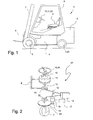
- the Fig. 1 schematically shows a side view of a counterbalance forklift, executed inventive truck 1 with an electric steering device 23 as an electric drive for a component of the mobile machine.
- a fork 3 On a mast 2, a fork 3 is arranged and on a frame 4 front wheels 5 and below a counterweight 6 at least one steered wheel 7 are arranged, which is provided with an electric drive for adjusting the steering angle.
- the invention can be used both in industrial trucks in 3-wheel design, as well as for industrial trucks in 4-wheel design can be used.
- a driver's cab 8 is a driver's seat 9 and before this a setpoint generator in the form of a steering transmitter 10 for the electric drive of the steering, here in the form of a steering wheel 11th
- the Fig. 2 schematically shows the electric drive as inventive electric steering 23 of the counterweight forklift from the Fig. 1 , Shown is the steering sensor 10 formed by the steering wheel 11, a steering shaft 12, a bearing 13 on the driver's cab 8 and a steering sensor sensor 14 as a setpoint generator.
- the steering sensor sensor 14 detects the angular position of the steering shaft 12 and outputs a corresponding signal via a signal line 15 to a control device 16 from.
- the control device 16 controls a converter 17, which receives an input voltage from a DC voltage intermediate circuit, not shown, and supplies the stator windings of a three-phase motor 18 designed as an asynchronous three-phase motor with current which is measured by stator current sensors (also not shown).
- the three-phase motor 18 rotates via a gear 19, which can be formed by a gear transmission, which is arranged on a turntable 20 steered wheel 7.
- a gear 19 a chain transmission or a belt transmission can be used.
- the control device 16 is connected to a Lüistwertsensor 22 which detects the steering angle of the steered wheel 7.
- the Fig. 3 schematically shows a circuit diagram of the inverter 17 and three-phase motor 18 of the electric drive of Fig. 1 ,
- a first half-bridge 24 for the first phase 25 has the power semiconductors V1 and V2, also referred to as current valves, with which positive or negative voltage from a traction battery 35 of the industrial truck 1 can be switched to the stator winding 26.
- a second half bridge 27 with power semiconductors V3 and V4 switches a second phase 28 onto the second stator winding 29 and a third half bridge 30 with power semiconductors V5 and V6 connects a third phase 31 onto the third stator winding 32.
- auxiliary half bridge 33 with power semiconductors V7 and V8 is connected to a star point 34 and can connect this star point 34 with the plus or minus voltage from the traction battery 35.
- the power semiconductors V7 and V8 of the auxiliary half-bridge 33 are open and the inverter 17 operates in a conventional manner.
- Fig. 4 schematically shows a circuit diagram of the inverter 17 of the electric drive of Fig. 1 in case of failure of the first phase 25, as indicated by the strikeout.
- For the control of the second stator winding 29 with the voltage U1 is now still the second phase 28 and the auxiliary half-bridge 33 and the third phase 31 via the star point 34 available.
- U d is the DC voltage of the intermediate circuit, with which the inverter 17 is fed, and which corresponds to the voltage of the traction battery 35 in the present example.
- the failure of the first phase 25 is illustrated by the "x". [X000] [X100] [X110] [X010] [X011] [X001] [X101] [X111] U 1 0 u d u d 0 - u d - u d 0 0 U 2 0 0 u d u d 0 - u d - u d 0 0
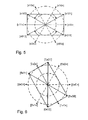
- the Fig. 5 4 schematically shows a space vector combination for the failure of the first phase 25.
- four each correspond to the remaining active base space pointers [x10x], [x01x] without switching of the first phase 25 and without switching of the auxiliary half-bridge 33.
- the four original base space vectors [110x], [010x] [110x], [010x] would result.
- the Fig. 6 schematically shows a space vector combination for the failure of the second phase 28. Shown are the four remaining active basic space hands [1x0x], [0x1x] without switching the second phase 28 and without switching the auxiliary half-bridge 33 as well as the original base space vector [1x1x] and [0x0x] of the second phase 28 that can no longer be switched.
- the resulting combinations of basic space [1x00], [ 1x01], [0x11], [0x10] of the system including the switched auxiliary half-bridge 33 shown in the complex plane must satisfy the above formula (2).
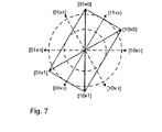
- the Fig. 7 schematically shows a space pointer combination for the failure of the third phase 31. Shown are the four remaining active base space pointers [10xx], [01xx] without switching the third phase 31 and without switching the auxiliary half-bridge 33 and the original base space pointer [11xx ] and [00xx] the no-switchable third phase 31.
- the resulting combinations of basic space pointers [10x0], [10x1], [01x1], [01x0] of the system including the switched auxiliary half-bridge 33, shown in the complex Level must satisfy the above formula (3).
Landscapes
- Engineering & Computer Science (AREA)
- Transportation (AREA)
- Mechanical Engineering (AREA)
- Structural Engineering (AREA)
- Chemical & Material Sciences (AREA)
- Combustion & Propulsion (AREA)
- Civil Engineering (AREA)
- Life Sciences & Earth Sciences (AREA)
- Geology (AREA)
- Power Engineering (AREA)
- Control Of Ac Motors In General (AREA)
- Electric Propulsion And Braking For Vehicles (AREA)
Applications Claiming Priority (2)
| Application Number | Priority Date | Filing Date | Title |
|---|---|---|---|
| DE102011114433 | 2011-09-28 | ||
| DE201110054620 DE102011054620A1 (de) | 2011-09-28 | 2011-10-19 | Flurförderzeug mit notbetriebsfähigem elektrischen Antrieb |
Publications (2)
| Publication Number | Publication Date |
|---|---|
| EP2574520A2 true EP2574520A2 (fr) | 2013-04-03 |
| EP2574520A3 EP2574520A3 (fr) | 2017-06-21 |
Family
ID=46880967
Family Applications (1)
| Application Number | Title | Priority Date | Filing Date |
|---|---|---|---|
| EP12183133.3A Withdrawn EP2574520A3 (fr) | 2011-09-28 | 2012-09-05 | Chariot de manutention doté d'un entraînement électrique à régime de secours |
Country Status (2)
| Country | Link |
|---|---|
| EP (1) | EP2574520A3 (fr) |
| DE (1) | DE102011054620A1 (fr) |
Cited By (5)
| Publication number | Priority date | Publication date | Assignee | Title |
|---|---|---|---|---|
| WO2015019787A1 (fr) * | 2013-08-05 | 2015-02-12 | 日立オートモティブシステムズ株式会社 | Dispositif de commande de moteur électrique et son procédé de commande |
| JP2015033272A (ja) * | 2013-08-05 | 2015-02-16 | 日立オートモティブシステムズ株式会社 | 電動モータの制御装置 |
| EP3012966A4 (fr) * | 2013-06-17 | 2017-03-01 | NSK Ltd. | Dispositif de commande de moteur, et dispositif de direction assistée électrique et véhicule les utilisant |
| EP3883127A1 (fr) * | 2020-03-16 | 2021-09-22 | Andrés Jiménez Olazábal | Dispositif d'activation de puissance et procédé pour un moteur électrique à phases multiples |
| DE102020111778A1 (de) | 2020-04-30 | 2021-11-04 | Gkn Sinter Metals Engineering Gmbh | Elektrische Schaltung für einen elektrischen Motor |
Family Cites Families (3)
| Publication number | Priority date | Publication date | Assignee | Title |
|---|---|---|---|---|
| US5491622A (en) * | 1994-01-07 | 1996-02-13 | Delco Electronics Corp. | Power converter with emergency operating mode for three phase induction motors |
| JP4609474B2 (ja) * | 2007-10-10 | 2011-01-12 | 株式会社デンソー | 回転電機装置 |
| DE102008027696A1 (de) * | 2008-05-26 | 2009-12-03 | Still Gmbh | Mobile Arbeitsmaschine mit Gleichspannungswandler |
-
2011
- 2011-10-19 DE DE201110054620 patent/DE102011054620A1/de not_active Withdrawn
-
2012
- 2012-09-05 EP EP12183133.3A patent/EP2574520A3/fr not_active Withdrawn
Non-Patent Citations (1)
| Title |
|---|
| None |
Cited By (7)
| Publication number | Priority date | Publication date | Assignee | Title |
|---|---|---|---|---|
| EP3012966A4 (fr) * | 2013-06-17 | 2017-03-01 | NSK Ltd. | Dispositif de commande de moteur, et dispositif de direction assistée électrique et véhicule les utilisant |
| US9634587B2 (en) | 2013-06-17 | 2017-04-25 | Nsk Ltd. | Motor control apparatus, electric power steering apparatus and vehicle using the same |
| WO2015019787A1 (fr) * | 2013-08-05 | 2015-02-12 | 日立オートモティブシステムズ株式会社 | Dispositif de commande de moteur électrique et son procédé de commande |
| JP2015033272A (ja) * | 2013-08-05 | 2015-02-16 | 日立オートモティブシステムズ株式会社 | 電動モータの制御装置 |
| JP2015033269A (ja) * | 2013-08-05 | 2015-02-16 | 日立オートモティブシステムズ株式会社 | 電動モータの制御装置 |
| EP3883127A1 (fr) * | 2020-03-16 | 2021-09-22 | Andrés Jiménez Olazábal | Dispositif d'activation de puissance et procédé pour un moteur électrique à phases multiples |
| DE102020111778A1 (de) | 2020-04-30 | 2021-11-04 | Gkn Sinter Metals Engineering Gmbh | Elektrische Schaltung für einen elektrischen Motor |
Also Published As
| Publication number | Publication date |
|---|---|
| DE102011054620A1 (de) | 2013-03-28 |
| EP2574520A3 (fr) | 2017-06-21 |
Similar Documents
| Publication | Publication Date | Title |
|---|---|---|
| DE69935372T2 (de) | Reduzierter Betrieb eines vielfach gewundenen Induktionsmotors nach einem Umrichterversagen | |
| DE112009004254B4 (de) | Elektrische Lenkhilfevorrichtung | |
| DE102006052423B4 (de) | Servolenkungsvorrichtung | |
| EP2447104B1 (fr) | Procédé de commande d'un générateur à champ tournant électrique d'une machine de travail mobile | |
| DE102011051234A1 (de) | Motoransteuervorrichtung und -verfahren und elektrisches Lenkhilfesystem, welches dieselbe verwendet | |
| DE102011051233A1 (de) | Motoransteuervorrichtung und -verfahren und elektrisches Lenkhilfesystem, welches dieselben verwendet | |
| WO2015090746A1 (fr) | Ensemble de commutation de sécurité pour une unité d'entraînement électrique | |
| EP2574520A2 (fr) | Chariot de manutention doté d'un entraînement électrique à régime de secours | |
| DE112018007643T5 (de) | Lenkeinrichtung | |
| WO2000072100A1 (fr) | Systeme de regulation avec surveillance de securite assistee par modele d'un organe de positionnement a regulation electronique monte dans un vehicule automobile | |
| EP4158769A1 (fr) | Dispositif de commande pour onduleur, système d'entraînement électrique et procédé pour établir un mode de fonctionnement sûr | |
| EP3378152B1 (fr) | Entraînement électrique pour un robot industriel | |
| EP0935336B2 (fr) | Méthode et dispositif de commande d' un moteur synchron | |
| EP2368785B1 (fr) | Procédé de commande d'un entraînement électrique d'une machine de travail mobile, notamment d'un actionnement de direction | |
| DE102011075789A1 (de) | Verfahren zum Betrieb einer Drehfeldmaschine | |
| EP1699676B1 (fr) | Procede de ralentissement d'un moteur electrique et mecanisme d'entrainement electrique | |
| DE102012207534A1 (de) | Auswahleinheit zur Auswahl der Konfiguration eines Elektromotors, Transportmaschine und zugehöriges Verfahren | |
| EP2706038B1 (fr) | Chariot de manutention avec moteur à reluctance synchrone | |
| DE112015000065T5 (de) | Spannungssteuerungsvorrichtung und Spannungssteuerungsverfahren | |
| EP2667496A2 (fr) | Chariot de manutention présentant un moteur de pompe électrique | |
| DE102020104437A1 (de) | Versatz der Stromgrundwellen bei mehrphasigen Antrieben | |
| WO2014095236A2 (fr) | Procédé pour la connexion électrique d'un convertisseur à une machine électrique | |
| DE102013109224A1 (de) | Steuerungsverfahren für einen elektrischen Antrieb einer mobilen Arbeitsmaschine | |
| EP2667495B1 (fr) | Chariot de manutention doté d'un moteur de pompe électrique | |
| DE112019000939T5 (de) | Verfahren zum Kompensieren eines Bremsmoments im Falle eines Kurzschlusses im Wechselrichter eines Hilfsmotors |
Legal Events
| Date | Code | Title | Description |
|---|---|---|---|
| PUAI | Public reference made under article 153(3) epc to a published international application that has entered the european phase |
Free format text: ORIGINAL CODE: 0009012 |
|
| AK | Designated contracting states |
Kind code of ref document: A2 Designated state(s): AL AT BE BG CH CY CZ DE DK EE ES FI FR GB GR HR HU IE IS IT LI LT LU LV MC MK MT NL NO PL PT RO RS SE SI SK SM TR |
|
| AX | Request for extension of the european patent |
Extension state: BA ME |
|
| PUAL | Search report despatched |
Free format text: ORIGINAL CODE: 0009013 |
|
| AK | Designated contracting states |
Kind code of ref document: A3 Designated state(s): AL AT BE BG CH CY CZ DE DK EE ES FI FR GB GR HR HU IE IS IT LI LT LU LV MC MK MT NL NO PL PT RO RS SE SI SK SM TR |
|
| AX | Request for extension of the european patent |
Extension state: BA ME |
|
| RIC1 | Information provided on ipc code assigned before grant |
Ipc: H02P 21/00 20160101ALI20170515BHEP Ipc: B66F 9/075 20060101ALI20170515BHEP Ipc: H02M 1/32 20070101ALI20170515BHEP Ipc: H02P 29/02 20160101ALI20170515BHEP Ipc: B62D 5/04 20060101ALI20170515BHEP Ipc: B66F 9/00 20060101ALI20170515BHEP Ipc: B62D 5/00 20060101AFI20170515BHEP |
|
| STAA | Information on the status of an ep patent application or granted ep patent |
Free format text: STATUS: REQUEST FOR EXAMINATION WAS MADE |
|
| 17P | Request for examination filed |
Effective date: 20171218 |
|
| RBV | Designated contracting states (corrected) |
Designated state(s): AL AT BE BG CH CY CZ DE DK EE ES FI FR GB GR HR HU IE IS IT LI LT LU LV MC MK MT NL NO PL PT RO RS SE SI SK SM TR |
|
| STAA | Information on the status of an ep patent application or granted ep patent |
Free format text: STATUS: THE APPLICATION IS DEEMED TO BE WITHDRAWN |
|
| 18D | Application deemed to be withdrawn |
Effective date: 20190402 |