EP2574517A2 - Vehicle control device, vehicle information monitoring device, vehicle information monitoring system, and vehicle control method - Google Patents
Vehicle control device, vehicle information monitoring device, vehicle information monitoring system, and vehicle control method Download PDFInfo
- Publication number
- EP2574517A2 EP2574517A2 EP12186028A EP12186028A EP2574517A2 EP 2574517 A2 EP2574517 A2 EP 2574517A2 EP 12186028 A EP12186028 A EP 12186028A EP 12186028 A EP12186028 A EP 12186028A EP 2574517 A2 EP2574517 A2 EP 2574517A2
- Authority
- EP
- European Patent Office
- Prior art keywords
- vehicle information
- vehicle
- conversion rule
- request
- communication unit
- Prior art date
- Legal status (The legal status is an assumption and is not a legal conclusion. Google has not performed a legal analysis and makes no representation as to the accuracy of the status listed.)
- Granted
Links
- 238000012806 monitoring device Methods 0.000 title claims abstract description 97
- 238000000034 method Methods 0.000 title claims description 14
- 238000012544 monitoring process Methods 0.000 title claims description 13
- 238000004891 communication Methods 0.000 claims abstract description 239
- 238000006243 chemical reaction Methods 0.000 claims abstract description 217
- 230000004044 response Effects 0.000 claims abstract description 99
- 230000005540 biological transmission Effects 0.000 claims abstract description 27
- 230000006870 function Effects 0.000 abstract description 4
- 239000000446 fuel Substances 0.000 description 16
- 239000002826 coolant Substances 0.000 description 15
- 238000003745 diagnosis Methods 0.000 description 13
- 230000008878 coupling Effects 0.000 description 8
- 238000010168 coupling process Methods 0.000 description 8
- 238000005859 coupling reaction Methods 0.000 description 8
- 238000010586 diagram Methods 0.000 description 6
- 238000012545 processing Methods 0.000 description 4
- 238000002485 combustion reaction Methods 0.000 description 3
- 238000002347 injection Methods 0.000 description 2
- 239000007924 injection Substances 0.000 description 2
- 238000012423 maintenance Methods 0.000 description 2
- 238000004519 manufacturing process Methods 0.000 description 2
- 230000005856 abnormality Effects 0.000 description 1
- 238000001816 cooling Methods 0.000 description 1
- 230000010485 coping Effects 0.000 description 1
- 230000001419 dependent effect Effects 0.000 description 1
- 238000013461 design Methods 0.000 description 1
- 238000001514 detection method Methods 0.000 description 1
- 238000011161 development Methods 0.000 description 1
- 238000007599 discharging Methods 0.000 description 1
- 230000007613 environmental effect Effects 0.000 description 1
- 239000000243 solution Substances 0.000 description 1
Images


Classifications
-
- B—PERFORMING OPERATIONS; TRANSPORTING
- B60—VEHICLES IN GENERAL
- B60K—ARRANGEMENT OR MOUNTING OF PROPULSION UNITS OR OF TRANSMISSIONS IN VEHICLES; ARRANGEMENT OR MOUNTING OF PLURAL DIVERSE PRIME-MOVERS IN VEHICLES; AUXILIARY DRIVES FOR VEHICLES; INSTRUMENTATION OR DASHBOARDS FOR VEHICLES; ARRANGEMENTS IN CONNECTION WITH COOLING, AIR INTAKE, GAS EXHAUST OR FUEL SUPPLY OF PROPULSION UNITS IN VEHICLES
- B60K35/00—Arrangement of adaptations of instruments
-
- B—PERFORMING OPERATIONS; TRANSPORTING
- B60—VEHICLES IN GENERAL
- B60W—CONJOINT CONTROL OF VEHICLE SUB-UNITS OF DIFFERENT TYPE OR DIFFERENT FUNCTION; CONTROL SYSTEMS SPECIALLY ADAPTED FOR HYBRID VEHICLES; ROAD VEHICLE DRIVE CONTROL SYSTEMS FOR PURPOSES NOT RELATED TO THE CONTROL OF A PARTICULAR SUB-UNIT
- B60W50/00—Details of control systems for road vehicle drive control not related to the control of a particular sub-unit, e.g. process diagnostic or vehicle driver interfaces
- B60W50/04—Monitoring the functioning of the control system
- B60W50/045—Monitoring control system parameters
-
- B—PERFORMING OPERATIONS; TRANSPORTING
- B60—VEHICLES IN GENERAL
- B60W—CONJOINT CONTROL OF VEHICLE SUB-UNITS OF DIFFERENT TYPE OR DIFFERENT FUNCTION; CONTROL SYSTEMS SPECIALLY ADAPTED FOR HYBRID VEHICLES; ROAD VEHICLE DRIVE CONTROL SYSTEMS FOR PURPOSES NOT RELATED TO THE CONTROL OF A PARTICULAR SUB-UNIT
- B60W50/00—Details of control systems for road vehicle drive control not related to the control of a particular sub-unit, e.g. process diagnostic or vehicle driver interfaces
- B60W50/08—Interaction between the driver and the control system
- B60W50/14—Means for informing the driver, warning the driver or prompting a driver intervention
-
- B—PERFORMING OPERATIONS; TRANSPORTING
- B60—VEHICLES IN GENERAL
- B60W—CONJOINT CONTROL OF VEHICLE SUB-UNITS OF DIFFERENT TYPE OR DIFFERENT FUNCTION; CONTROL SYSTEMS SPECIALLY ADAPTED FOR HYBRID VEHICLES; ROAD VEHICLE DRIVE CONTROL SYSTEMS FOR PURPOSES NOT RELATED TO THE CONTROL OF A PARTICULAR SUB-UNIT
- B60W50/00—Details of control systems for road vehicle drive control not related to the control of a particular sub-unit, e.g. process diagnostic or vehicle driver interfaces
- B60W2050/0062—Adapting control system settings
- B60W2050/0075—Automatic parameter input, automatic initialising or calibrating means
-
- B—PERFORMING OPERATIONS; TRANSPORTING
- B60—VEHICLES IN GENERAL
- B60W—CONJOINT CONTROL OF VEHICLE SUB-UNITS OF DIFFERENT TYPE OR DIFFERENT FUNCTION; CONTROL SYSTEMS SPECIALLY ADAPTED FOR HYBRID VEHICLES; ROAD VEHICLE DRIVE CONTROL SYSTEMS FOR PURPOSES NOT RELATED TO THE CONTROL OF A PARTICULAR SUB-UNIT
- B60W50/00—Details of control systems for road vehicle drive control not related to the control of a particular sub-unit, e.g. process diagnostic or vehicle driver interfaces
- B60W50/08—Interaction between the driver and the control system
- B60W50/14—Means for informing the driver, warning the driver or prompting a driver intervention
- B60W2050/146—Display means
-
- B—PERFORMING OPERATIONS; TRANSPORTING
- B60—VEHICLES IN GENERAL
- B60W—CONJOINT CONTROL OF VEHICLE SUB-UNITS OF DIFFERENT TYPE OR DIFFERENT FUNCTION; CONTROL SYSTEMS SPECIALLY ADAPTED FOR HYBRID VEHICLES; ROAD VEHICLE DRIVE CONTROL SYSTEMS FOR PURPOSES NOT RELATED TO THE CONTROL OF A PARTICULAR SUB-UNIT
- B60W2556/00—Input parameters relating to data
- B60W2556/45—External transmission of data to or from the vehicle
Definitions
- the present invention relates to a vehicle control device, a vehicle information monitoring device for obtaining vehicle information from the vehicle control device, a vehicle information monitoring system, and a vehicle control method.
- a vehicle includes a display unit that displays vehicle information such as a vehicle speed and a vehicle control unit for controlling respective sections (mainly, electrical components) of the vehicle.
- the vehicle control unit controls, for example, the operation of electrical components such as an ignition plug and fuel injector included in a vehicle engine.
- Sensors necessary for such a control operation are connected to the vehicle control unit.
- the sensors include, for example, a vehicle speed sensor, an engine speed sensor, a coolant sensor, an intake temperature sensor, and a throttle opening degree sensor.
- the display unit is arranged so as to obtain necessary information by communication with the vehicle control unit.
- the display unit is arranged so as to obtain information such as a vehicle speed, an engine speed, and a coolant temperature from the vehicle control unit and display the information.
- JP' 642 discloses a fault diagnosis tool to be connected to an engine controller.
- the fault diagnosis tool provides an obtaining request for engine related data to the engine controller.
- the engine controller sends values of various parameters such as an engine speed and a vehicle speed back to the fault diagnosis tool.
- the fault diagnosis tool has a physical quantity conversion information storage section storing physical quantity conversion formulas stored in advance for each parameter.
- the fault diagnosis tool converts a parameter received from the engine controller to a value that matches an actual physical quantity (an engine speed, a vehicle speed, or the like) in accordance with the physical quantity conversion formula stored in the physical quantity conversion information storage section.
- the physical quantity conversion information storage section is provided inside of a memory cartridge that is detachably attached to the fault diagnosis tool.
- the vehicle control unit includes a memory that stores vehicle information and a communication port for reading out vehicle information from the memory in some cases. By reading out vehicle information stored in the memory via the communication port, a fault diagnosis of the vehicle can be performed.
- vehicle information to be output by a vehicle control device such as an engine controller is not information that can be used as it is, but needs to be converted in accordance with a conversion rule such as a physical quantity conversion formula.
- the conversion rules are different, for example, for each type of vehicle, and thus it is necessary that another device for obtaining vehicle information by communication with a vehicle control device has conversion rules adopted in the vehicle control device in common.
- a dedicated device that is mounted on a vehicle together with a vehicle control device and communicates with the vehicle control device has such conversion rules in common.
- the same conversion rules as those in the vehicle control device must be held in common.
- a conversion rule table that stores the names of the plurality of types of vehicles and a plurality of corresponding conversion rules must be included in the vehicle information monitoring device. This means that the conversion rule table must be updated when a new type of vehicle is developed. Therefore, a great amount of labor is required for preparing an updated conversion rule table, and a greater amount of labor is required for writing the updated conversion rule table in the vehicle information monitoring device.
- said object is solved by a vehicle control device having the features of claim 1, a vehicle information monitoring device having the features of claim 3, a vehicle information monitoring system having the features of claim 5 or 6, and a vehicle control method having the features of claim 9.
- Preferred embodiments are laid down in the dependent claims.
- a vehicle control device including a communication unit for communication with an external communication target, a response data transmission control unit that, in response to a request code to request vehicle information being received by the communication unit, transmits response data including vehicle information corresponding to the request code from the communication unit, and a conversion rule transmission control unit that, in response to a conversion rule request requesting a conversion rule to convert vehicle information being received by the communication unit, transmits a conversion rule corresponding to the conversion rule request from the communication unit.
- the vehicle control device is arranged so as to respond to a request code to request vehicle information. That is, when a request code is received by the communication unit, a response code including vehicle information corresponding to the request code is transmitted from the communication unit. Furthermore, the vehicle control device is arranged so as to respond to a conversion rule request requesting a conversion rule to convert vehicle information. That is, when a conversion rule request is received by the communication unit, a conversion rule corresponding to the request is transmitted from the communication unit.
- another external device that communicates with the vehicle control device via a communication unit, that is, a communication target, can obtain a conversion rule by providing a conversion rule request to the vehicle control device, and further, by providing a request code to the vehicle control unit device, can obtain vehicle information included in a response code from the vehicle control device.
- the other device can convert vehicle information by a correct conversion rule.
- the vehicle information is information that the vehicle control device can hold internally.
- Examples of the vehicle information that can be mentioned include a motor rotationspeed, avehiclespeed, acoolanttemperature, anintake air temperature, a throttle opening degree, a gear position, and a remaining fuel amount.
- the vehicle information may include sensor output information output by sensors mounted on the vehicle. Examples of the sensor output information include a motor rotation speed, a vehicle speed, a coolant temperature, an intake air temperature, a throttle opening degree, a gear position, and a remaining fuel amount.
- the vehicle information may include calculation information prepared by internal calculation of the vehicle control device. Examples of the calculation information that can be mentioned include a control command such as a fuel injection amount (fuel injection time) and various warnings.
- the gear position can also be an example of control command information.
- the motor of the vehicle may be either an internal combustion engine or an electric motor.
- the coolant temperature is the temperature of a coolant to cool an engine, which is an example of the motor.
- the intake air temperature is the temperature of air to be taken in an engine, and can be used as an alternative indicator of an environmental temperature.
- the warning is information to notify an abnormality such as a fault.
- the gear position is information indicating the gear position of a transmission included in the vehicle.
- the request code may be a code that specifies the type of vehicle information and requests transmission thereof.
- the vehicle control device may be arranged, for example, so as to control electrical components included in the vehicle.
- the electrical components include electrical components related to an engine as an example of the motor. Specific examples of such electrical components include components related to driving of an engine, such as an ignition plug (ignition coil), a fuel injector, and a fuel pump.
- the vehicle control device is input with output signals of sensors. Specific examples of the sensors include a vehicle speed sensor, an engine speed sensor, a coolant temperature sensor, and an intake air temperature sensor.
- the engine speed sensor includes, for example, a crank angle sensor that detects the rotation angle of a crankshaft of the engine.
- examples of the conversion rule include not only a conversion parameter such as a resolution but also a conversion rule specifying code to specify a conversion rule like a resolution specifying code to specify a resolution and a conversion formula specifying code to specify a conversion formula.
- the resolution specifying code is a code (e.g. a number), for which a plurality of types of selectable resolutions are predetermined, for selecting and specifying one of the predetermined resolutions.
- the conversion formula specifying code is a code (e. g. a number), for which a plurality of types of selectable conversion formulas are predetermined, for selecting and specifying one of the predetermined conversion formulas.
- the conversion rule may be a rule for converting the form of vehicle information that is handled inside of the vehicle control device and is output from the communication unit to another form that allows handling in an external communication target.
- vehicle information before conversion by the conversion rule and vehicle information after the conversion are different in form, but express, for example, the same physical quantity.
- the communication unit includes a communication port for communicating with a vehicle information display device that displays vehicle information.
- information can be obtained from the vehicle control device by using the communication port to connect a vehicle information display device.
- vehicle information from the vehicle control device can be obtained by connecting a vehicle information monitoring device to the communication port.
- a vehicle information monitoring device For example, there is a strict limit to the size of a vehicle control device of a saddle type vehicle such as a two-wheeled motor vehicle because of limitation in mounting space. For this reason, there is no allowance for including a dedicated communication port for a fault diagnosis etc. Therefore, as a result of being able to use the communication port for the vehicle information display device also for a fault diagnosis etc., an increase in size of the vehicle control device can be avoided, while a fault diagnosis function can be added.
- a preferred embodiment of the present invention provides a vehicle information monitoring device for obtaining vehicle information from the vehicle control device as described above, and includes a first communication unit that communicates with the communication unit of the vehicle control device, a request code transmission control unit that causes the first communication unit to transmit a request code to request vehicle information, a conversion rule request transmission control unit that causes the first communication unit to transmit a conversion rule request requesting a conversion rule for vehicle information, a response code reception control unit that receives from the vehicle control device a response code corresponding to the request code by the first communication unit, a conversion rule reception control unit that receives from the vehicle control device a conversion rule corresponding to the conversion rule request by the first communication unit, and a converter unit that converts vehicle information included in a response code received by the response code reception control unit in accordance with a conversion rule received by the conversion rule reception control unit.
- the vehicle information monitoring device obtains vehicle information by providing a request code to the vehicle control device and receiving a response code transmitted from the vehicle control device in response thereto. Moreover, the vehicle information monitoring device provides a conversion rule request to the vehicle control device, and obtains a conversion rule sent from the vehicle control device in response thereto. Then, the vehicle information monitoring device converts the vehicle information included in the response code in accordance with the conversion rule, and thereby obtains vehicle information after conversion (an actual physical amount). Due to such an arrangement, the vehicle information monitoring device can convert vehicle information by a correct conversion rule without having in advance the same conversion rule as that of the vehicle control device in common.
- the vehicle information monitoring device even when a plurality of vehicle control devices respectively output vehicle information different in conversion rules, it is not necessary for the vehicle information monitoring device to include a conversion rule table that stores type-by-type conversion rules of vehicles, and of course, it is not necessary to update the conversion rule table. That is, vehicle information output by the vehicle control devices of apluralityof types of vehicles can be monitored by the vehicle information monitoring device of the same specifications.
- the vehicle information monitoring device further includes a second communication unit that communicates with a vehicle information display device for displaying vehicle information by communicating with the communication unit of the vehicle control device, and a response code transmission control unit that causes the second communication unit to transmit a response code when a response code is received by the response code reception control unit, and the response code transmission control unit is arranged so as to cause the first communication unit to transmit a request code when the second communication unit receives a request code.
- the vehicle information display device when this is connected to the vehicle control device, can obtain vehicle information by communication with the vehicle control device. Specifically, the vehicle information display device generates a request code to request necessary information. The vehicle control device, upon receiving the request code, generates response data (including vehicle information) corresponding to the request code. The vehicle information display device, by use of the vehicle information included in the response data, performs a necessary display.
- the vehicle information monitoring device is arranged so as to communicate with the vehicle control device by the first communication unit and communicate with the vehicle information display device by the second communication unit. Therefore, the vehicle information monitoring device can relay communication between the vehicle information display device and the vehicle control device. That is, the vehicle information monitoring device can transmit a request code received from the vehicle information display device to the vehicle control device, receive response data for the request code from the vehicle control device, and transmit the response data to the vehicle information display device. Accordingly, the vehicle information monitoring device can provide necessary information for the vehicle information display device, and can monitor vehicle information. That is, the vehicle information monitoring device can sustain a display operation in the vehicle information display device, while monitoring vehicle information.
- the vehicle information to be displayed by the vehicle information display device includes, for example, one or more of the vehicle speed, motor rotation speed, coolant temperature, intake air temperature, warning, gear position, and remaining fuel amount. That is, the vehicle information display device may be supplied with the information by the vehicle control device. It is preferable that the vehicle information to be displayed by the vehicle information display device includes at least the foregoing sensor output information. More specifically, it is preferable that the vehicle information to be displayed by the vehicle information display device includes at least the vehicle speed and motor rotation speed.
- a preferred embodiment of the present invention provides a vehicle information monitoring system including the vehicle control device and vehicle information monitoring device as described above.
- a preferred embodiment of the present invention provides a vehicle information monitoring system including the vehicle control device as described above, the vehicle information monitoring device as described above, and a vehicle information display device that communicates with the second communication unit.
- the vehicle control device and the vehicle information display device are arranged so as to be able to be connected by a wired communication line having halfway a first connector and a second connector that can couple with each other, the first connector is connected to the vehicle control device, and the second connector is connected to the vehicle information display device, and the first communication unit includes a first connecting portion to be connected to the first connector, and the second communication unit includes a second connecting portion to be connected to the second connector.
- the vehicle control device and the vehicle information display device are connected by a wired communication line, and a first connector and a second connector that can couple with each other are provided halfway on the wired communication line.
- the first connector and the second connector are coupled, and the vehicle control device and the vehicle information display device carry out information communication directly.
- the vehicle control device and the vehicle information display device can be relayed by the vehicle information monitoring device, while communicating with each other.
- the vehicle information monitoring device respectively communicates with the vehicle control device and the vehicle information display device.
- the "halfway on the wired communication line” means any position from one end to the other end of the wired communication line. That is, an intermediate portion, a one-end portion, and an other-end portion of a wired communication line are all covered by the "halfway on the wired communication line.”
- the vehicle information monitoring device relays a request code and response data between the vehicle control device and the vehicle information display device.
- the vehicle information monitoring device can cause the vehicle control device and the vehicle information display device to perform communication therebetween by relaying therebetween, while obtaining vehicle information. Therefore, vehicle information can be obtained in a driving state of the vehicle.
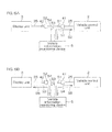
- FIG. 1 is a block diagram for explaining an electrical configuration of a vehicle to which a vehicle information monitoring device according to a preferred embodiment of the present invention is applicable, and shows a normal use state of a vehicle.
- FIG. 2 is a block diagram for explaining a configuration of the vehicle information monitoring device according to the preferred embodiment of the present invention, and shows a configuration when obtaining vehicle information.
- FIG. 3 is a block diagram for explaining a functional configuration of a vehicle control unit and a vehicle information monitoring device.
- FIG. 4 is a view showing examples of data that appear on a wired communication line in the normal use state (refer to FIG. 1 ) of a vehicle.
- FIG. 5 is a view showing a communication timing between a display unit and a vehicle control unit in the normal use state (refer to FIG. 1 ) of a vehicle.
- FIG. 6A and FIG. 6B are views for explaining a communication procedure when the vehicle information monitoring device is connected between the display unit and the vehicle control unit (refer to FIG. 2 ).
- FIG. 7A is a timing chart showing a communication timing corresponding to the communication procedure of FIG. 6A .
- FIG. 7B is a timing chart showing a communication timing corresponding to the communication procedure of FIG. 6B .
- FIG. 1 is a block diagram for explaining an electrical configuration of a vehicle to which a preferred embodiment of the present invention can be applied.
- the vehicle 10 includes an engine, 1, a vehicle control unit 2 as an example of a vehicle control device, and a display unit 3 as an example of a vehicle information display device.
- the vehicle control unit 2 is programmed so as to control the operation of electrical components related to the vehicle 10. More specifically, the vehicle control unit 2 is mounted on the vehicle 10, and controls the operation of electrical components included in the engine 1 and electrical components related to the engine 1.
- the engine 1, in the present preferred embodiment, is an internal combustion engine. In the engine 1, an ignition coil 11 and a fuel injector 12 are included as electrical components.
- the ignition coil 11 is arranged so as to apply a high voltage to discharge an ignition plug to the ignition plug.
- the ignition plug includes a discharging section that discharges inside a combustion chamber of the engine 1.
- the fuel injector 12 is a device that injects fuel toward an intake port of the engine 1.
- a fuel pump 18 for supplying fuel to the fuel injector 12 is also one of the electrical components related to the engine 1. The operation of the fuel pump 18 is also controlled by the vehicle control unit 2.
- the engine 1 further includes a crank angle sensor 13, a coolant temperature sensor 14, an intake temperature sensor 15, and a throttle opening degree sensor 16.
- the crank angle sensor 13 is arranged so as to detect the rotation angle of a crankshaft of the engine 1.
- the coolant temperature sensor 14 is arranged so as to detect the temperature of a coolant for cooling the engine 1.
- the intake temperature sensor 15 is arranged so as to detect the temperature of air (intake air) to be taken in the engine 1.
- the throttle opening degree sensor 16 is arranged so as to detect the opening degree of a throttle valve included in the engine 1. Output signals of the sensors 13, 14, 15, and 16 are input to the vehicle control unit 2.
- a vehicle speed sensor 17 that detects the traveling speed (vehicle speed) of the vehicle 10 is connected.
- the vehicle control unit 2 further includes an input interface 20 towhich detection signals from the sensors 13 to 17 are input.
- the vehicle control unit 2 includes an actuator drive circuit 21 for driving electrical components (actuators) included in the engine 1 and electrical components (actuators, e.g. a fuel pump) included in parts other than the engine 1 of the vehicle 10.
- the vehicle control unit 2 further includes a communication interface 22 serving as communication units, a microcomputer 23, a vehicle information memory 24, and a conversion rule memory 26.
- the communication interface 22 is arranged so as to perform give/receive of commands and data with a communication cable 25, and provides a communication port for communicating with the display unit 3.
- the microcomputer 23 is programmed so as to control the actuator drive circuit 21 according to output signals etc., of the sensors input to the input interface 20.
- the vehicle information memory 24 is arranged so as to hold, for example, output signals of the sensors input to the input interface 20 anda control historyof electrical components by the actuator drive circuit 21 as vehicle information (vehicle control information). More specifically, there is an arrangement so that the microcomputer 23 writes the vehicle information in the vehicle information memory 24.
- the microcomputer 23 is also programmed so as to, according to a request code received by the communication interface 22, read necessary vehicle information out of the vehicle information memory 24, and send out response data including the vehicle information to the communication cable 25.
- the conversion rule memory 26 stores a conversion rule for the vehicle control unit 2 converting vehicle information transmitted by the vehicle control unit 2 from the communication interface 22 into an actual physical quantity.
- the "actual physical quantity” herein means a physical quantity expressed in a form of expression that a human being ordinarily understands. More specifically, an engine speed resolution and a vehicle speed resolution corresponding to engine speed data and a vehicle speed transmitted by the vehicle control unit 2 from the communication interface 22, respectively, are stored as conversion rules in the conversion rule memory 26.
- the engine speed resolution is an actual physical quantity expressed by the minimum unit of engine speed data. For example, it is assumed that the engine speed data is 1 byte (0 ⁇ 255) of data.
- the vehicle information transmitted by the vehicle control unit 2 from the communication interface 22 is expressed in a form different from that a human being ordinarily understands.
- the value before conversion by a conversion rule and the value after the conversion are different in the form of expression, but express the same physical quantity. That is, the "actual physical quantity" obtained by converting vehicle information by a conversion rule is vehicle information converted in the form of expression.
- the conversion rule may indicate a rule to convert a predetermined length of data that is handled inside the vehicle control unit 2 and output from the communication interface 22 into a longer length of data (data long enough to be made into a form that a human being can understand).
- the microcomputer 23 is programmed so as to, according to a packet including a conversion rule request received by the communication interface 22, read a corresponding conversion rule out of the conversion rule memory 26, and send out a packet including the conversion rule to the communication cable 25.
- a first connector (coupler) 41 is coupled to the distal end of the communication cable 25 .
- the display unit 3 is connected to a communication cable 35.
- a second connector (coupler) 42 is coupled to the distal end of the communication cable 35.
- the first connector 41 and the second connector 42 are arranged so as to be capable of coupling with each other and releasing the coupling.
- the display unit 3 is mounted on the vehicle 10, and includes a meter display section 31, a communication interface 32, a microcomputer 33, and a conversion rule memory 34.
- the conversion rule memory 34 the same conversion rule as that in the conversion rule memory 26 of the vehicle control unit 2 is stored.
- the meter display section 31 is arranged so as to be capable of displaying, for example, a vehicle speed, an engine speed, a warning, a coolant temperature, and an intake air temperature.
- the information to be displayed is obtained from the vehicle control unit 2, via a wired communication line 30 including the communication cables 25 and 35, by the communication interface 32.
- the microcomputer 33 is programmed so as to send out, from the communication interface 32 to the communication cable 35, a request code to request vehicle information necessary for a display.
- the microcomputer 33 is arranged so as to extract vehicle information from a response code received by the communication interface 32 from the communication cable 35.
- the microcomputer 33 is further programmed so as to control the meter display section 31 in order to cause the meter display section 31 to display the extracted vehicle information.
- the microcomputer 33 upon obtaining engine speed data by the communication interface 32, reads an engine speed resolution out of the conversion rule memory 34, and multiplies the engine speed data by the engine speed resolution to determine an engine speed. The microcomputer 33 then provides an engine speed display control signal according to the determined engine speed to the meter display section 31. Similarly, the microcomputer 33, upon obtaining vehicle speed data by the communication interface 32, reads a vehicle speed resolution out of the conversion rule memory 34, and multiplies the vehicle speed data by the vehicle speed resolution to determine a vehicle speed. The microcomputer 33 then provides a vehicle speed display control signal according to the determined vehicle speed to the meter display section 31.
- FIG. 2 is a block diagram for explaining the configuration of a vehicle information monitoring device 5.
- the vehicle information monitoring device 5 is arranged so as to be connected between the vehicle control unit 2 and the display unit 3 and relay information communication between the vehicle control unit 2 and the display unit 3. That is, the vehicle information monitoring device 5 is arranged so as to function as a relay unit to relay information communication between the vehicle control unit 2 and the display unit 3.
- the vehicle information monitoring device 5 is not mounted on the vehicle 10 in normal use of the vehicle 10. That is, the vehicle information monitoring device 5 is connected between the vehicle control unit 2 and the display unit 3 when necessary. In this connected state, the vehicle information monitoring device 5 may be temporarily held in the vehicle 10, or may be placed at a place other than the vehicle 10.
- the vehicle information monitoring device 5 may be temporarily held on the vehicle 10, or the vehicle information monitoring device 5 may be held in a retainer (a bag, a belt, or the like) that an occupant carries with him/her.
- a retainer a bag, a belt, or the like
- the vehicle information monitoring device 5 has a first connecting portion 51 and a second connecting portion 52.
- the first connecting portion 51 is connected with the first connector 41 connected to the vehicle control unit 2 via the communication cable 25.
- the second connecting portion 52 is connected with the second connector 42 connected to the display unit 3 via the communication cable 35. More specifically, the first connecting portion 51 has a form of a connector capable of coupling with the first connector 41.
- the second connecting portion 52 similarly has a formof a connector capable of coupling with the second connector 42.
- the first connecting portion 51 is connected, via a communication cable 53, to a circuit board provided inside the casing of the vehicle information monitoring device 5.
- the second connecting portion 52 is connected, via a communication cable 54, to a circuit board provided inside the casing of the vehicle information monitoring device 5.
- the vehicle information monitoring device 5 includes a first communication interface 61, a second communication interface 62, a microcomputer 55, a third communication interface 63, a conversion rule memory 56, and a nonvolatile memory 58.
- the first communication interface 61 forms a first communication unit together with the first connecting portion 51 and the communication cable 53.
- the first communication interface 61 is a communication interface for communication with the vehicle control unit 2.
- the second communication interface 62 forms a second communication unit together with the second connecting portion 52 and the communication cable 54.
- the second communication interface 62 is a communication interface for communication with the display unit 3.
- the third communication interface 63 is a communication interface for communication with an external processor 70 (e.g. a personal computer incorporated with a predetermined tool).
- the conversion rule memory 56 is a storage unit for temporarily storing a conversion rule received from the display unit 3.
- the nonvolatile memory 58 is a storage unit for storing response data (vehicle information) obtained from the vehicle control unit 2. With regard to vehicle information that needs to be converted into an actual physical quantity by use of a conversion rule, vehicle information after conversion is stored in the nonvolatile memory 58.
- the microcomputer 55 is programmed so as to cause the first communication interface 61 to send out a request code received by the second communication interface 62 from the display unit 3 to the vehicle control unit 2. Moreover, the microcomputer 55 is programmed so as to cause the second communication interface 62 to send out a response code received by the first communication interface 61 from the vehicle control unit 2 to the display unit 3. Further, the microcomputer 55 is programmed so as to write a part or the whole of response data received from the vehicle control unit 2 by the first communication interface 61 in the nonvolatile memory 58 as it is or after converting based on a conversion rule. Still moreover, the microcomputer 55 is programmed so as to accept an output request for response data, from the external processor 70, via the third communication interface 63.
- the microcomputer 55 is programmed so as to, in response to the output request, read storage data out of the nonvolatile memory 58, and send out the read-out data from the third communication interface 63.
- the microcomputer 55 may have an operation mode for outputting response data received by the second communication interface 62 from the third communication interface 63 in place of the storage data of the nonvolatile memory 58.
- the microcomputer 55 is further programmed so as to transmit, from the first communication interface 61 to the vehicle control unit 2, a conversion rule request requesting transmission of a conversion rule.
- the microcomputer 55 is programmed so as to, when the first communication interface 61 receives a conversion rule from the vehicle control unit 2, store the conversion rule in the conversion rule memory 56.
- the microcomputer 55 is programmed so as to, when the first communication interface 61 receives response data, apply a conversion rule stored in the conversion rule memory 56 according to the type of vehicle information in the response data to convert the vehicle information.
- the vehicle information monitoring device 5 is provided in, for example, a service center or the like for maintenance of the vehicle 10. That is, in a normal use state of the vehicle 10, the vehicle information monitoring device 5 is not mounted on the vehicle 10. That is, in a normal use state of the vehicle 10, the vehicle 10 has an electrical configuration as shown in FIG. 1 . Therefore, the vehicle control unit 2 and the display unit 3 mutually perform information communication via the wired communication line 30.
- the vehicle information monitoring device 5 When the vehicle 10 is taken in the service center or the like and it becomes necessary to obtain vehicle information in the vehicle control unit 2, the vehicle information monitoring device 5 is connected between the vehicle control unit 2 and the display unit 3 to reach the configuration shown in FIG. 2 . By driving the vehicle 10 in this state, vehicle information can be obtained from the vehicle control unit 2 and stored in the nonvolatile memory 58. The vehicle information received from the vehicle control unit 2 and the vehicle information stored in the nonvolatile memory 58 can be taken out to the outside via the third communication interface 63.
- the nonvolatile memory 58 may be formed by a memory unit that can be detachably attached to the vehicle information monitoring device 5.
- a specific example of the memory unit is a flash memory unit represented by a memory card and a USB memory.
- the vehicle information monitoring device 5 includes a reader/writer unit for reading and writing data for the memory unit.
- FIG. 3 is a block diagram for explaining a functional configuration of the principal parts of the vehicle control unit 2 and the vehicle information monitoring device 3.
- the microcomputer 23 of the vehicle control unit 2 substantially includes a plurality of functional processing sections to be implemented by software processing.
- the functional processing sections include a response data transmission control unit 231 and a conversion rule transmission control unit 232.
- the response data transmission control unit 231 is arranged so as to, in response to a request code to request vehicle information being received by the communication interface 22, read vehicle information corresponding to the request code out of the vehicle information memory 24, and cause the communication interface 22 to transmit response data including the vehicle information.
- the conversion rule transmission control unit 232 is arranged so as to, in response to a conversion rule request requesting a conversion rule to convert vehicle information being received by the communication interface 22, read a conversion rule corresponding to the conversion rule request out of the conversion rule memory 26, and cause the communication interface 22 to transmit the conversion rule.
- the microcomputer 55 of the vehicle information monitoring device 5 substantially includes a plurality of functional processing sections to be implemented by software processing.
- the functional processing sections include a request code transmission control unit 551, a conversion rule request transmission control unit 552, a response code reception control unit 553, a conversion rule reception control unit 554, a converter unit 555, a response code transmission control unit 556.
- the request code transmission control unit 551 is arranged so as to, when the second communication interface 62 receives a request code, cause the first communication interface 61 to transmit a request code to request vehicle information.
- the conversion rule request transmission control unit 552 is arranged so as to cause the first communication interface 61 to transmit a conversion rule request requesting a conversion rule for vehicle information.
- the response code reception control unit 553 is arranged so as to receive by the first communication interface 61 a response code corresponding to the request code from the vehicle control unit 2.
- the conversion rule reception control unit 554 is arranged so as to receive by the first communication interface 61 a conversion rule corresponding to the conversion rule request from the vehicle control unit 2.
- the received conversion rule is stored in the conversion rule memory 56.
- the converter unit 555 is arranged so as to convert vehicle information included in a response code received by the response code reception control unit 553 in accordance with a conversion rule received by the conversion rule reception control unit 554 and stored in the conversion rule memory 56.
- the vehicle information after conversion is stored in the nonvolatile memory 58.
- the response code transmission control unit 556 is arranged so as to, when a response code is received by the response code reception control unit 553 , cause the second communication interface 62 to transmit a response code.
- FIG. 4 is a view showing examples of data that appear on the wired communication line 30 in the normal use state (refer to FIG. 1 ) of the vehicle 10.
- the display unit 3 repeatedly sends out request codes to the wired communication line 3 at a predetermined period (e.g. 15.625msec).
- the request code may be 1 byte of data.
- the request code has a value determined according to information that needs to be obtained from the vehicle control unit 2. For example, by determining the value of the request code as "0x01,” the request code serves as a request code to request coolant temperature data. In this case, the vehicle control unit 2 sends out coolant temperature data as response data.
- the response data to be sent out to the wired communication line 30 by the vehicle control unit 2 in response to the request code consists of, for example, data D1, D2, D3, D4, and D5.
- Each of the data D1 to D5 is, for example, 1 byte of data. That is, the vehicle control unit 2 is arranged so as to send out 5 bytes of response data in response to one request code.
- the data D1 indicates an engine speed
- the data D2 indicates a vehicle speed
- the data D3 indicates warning information
- the data 4 indicates vehicle information (a coolant temperature or the like) according to the content of the request code
- the data D5 indicates checksum data of the data D1 to D4.
- the warning information is information indicating whether there is a fault and the fault type.
- the checksum data may be, for example, 8 low-order bits of an integrated value of the data D1 to D4.
- first 3 bytes of data D1 to D3 are data that the vehicle control unit 2 sends out every time receiving a request code. That is, the engine speed, vehicle speed, and warning information are sent out to the wired communication line 30 irrespective of the content of the request code.
- the fourth byte of data D4 includes second vehicle information that varies according to the content of the request code received by the vehicle control unit 2.
- the second vehicle information is information whose display priority in the display unit 3 is lower than that of the first vehicle information.
- FIG. 5 is a view showing a communication timing between the display unit 3 and the vehicle control unit 2 in the normal use state (refer to FIG. 1 ) of the vehicle 10.
- the display unit 3 repeatedly sends out request codes A, B, and C sequentially at a predetermined fixed period (request code generating period).
- the vehicle control unit 2 having received the request codes A, B, and C sends out response data D1 to D5 each time of reception.
- the response data D1 to D5 are received by the display unit 3. It is structured so that sending out of the request codes from the display unit 3 and sending out of the response data D1 to D5 from the vehicle control unit 2 are completed within the request code generating period by the display unit 3.
- FIG. 6A and FIG. 6B are views for explaining communication procedures when the vehicle information monitoring device 5 is connected between the display unit 3 and the vehicle control unit 2 (refer to FIG. 2 ).
- FIG. 7A and FIG. 7B are timing charts showing communication timings thereof.
- the microcomputer 55 of the vehicle information monitoring device 5 sends out a communication mode switching request from the first communication interface 61 to the vehicle control unit 2 to request switching to a multiple-byte communication mode.
- the microcomputer 23 of the vehicle control unit 2 when the communication interface 22 receives the communication mode switching request, switches communication modes to a multiple-byte communication mode from a single-byte communication mode, which is a normal communication mode.
- the microcomputer 55 of the vehicle information monitoring device 5 transmits, from the first communication interface 61 to the vehicle control unit 2, a conversion rule request (S1 of FIG. 6A ).
- the microcomputer 23 of the vehicle control unit 2 when the communication interface 22 receives the conversion rule request, reads a conversion rule out of the conversion rule memory 26, and transmits the read-out conversion rule from the communication interface 22 to the vehicle information monitoring device 5 (S2 of FIG. 6A ).
- the microcomputer 55 of the vehicle information monitoring device 5, when the first communication interface 61 receives the conversion rule stores the conversion rule in the conversion rule memory 56.
- Conversion rules to be obtained from the vehicle control unit 2 include, for example, resolutions related to vehicle information indicating numerical values like an engine speed, a vehicle speed, a coolant temperature, etc.
- the microcomputer 55 of the vehicle information monitoring device 5 causes the first communication interface 61 to repeatedly send out a conversion rule request.
- the microcomputer 55 may be arranged so as to identify the type (engine speed, vehicle speed, or the like) of vehicle information and cause the first communication interface 61 to send out a conversion rule request requesting a conversion rule for the identified vehicle information.
- the operator powers off the vehicle control unit 2. Specifically, the vehicle 10 with the vehicle control unit 2 mounted is powered off. Then, the operator again powers on the vehicle control unit 2 (more specifically, the vehicle 10). Accordingly, the communication mode of the vehicle control unit 2 returns to the normal communication mode (single-byte communication mode).
- the display unit 3 as in the case of a normal use state, sends out request codes A, B, and C to the communication cable 35 at a predetermined period (e.g. 15.625msec) (S3 of FIG. 6B ).
- the request code sent out by the display unit 3 is received by the vehicle information monitoring device 5.
- the vehicle information monitoring device 5 transmits the request code received from the display unit 3 to the vehicle control unit 2 via the communication cable 53 (S4 of FIG. 6B ).
- the microcomputer 23 of the vehicle control unit 2 when the communication interface 22 receives the request code, transmits response data including vehicle information corresponding to the request code from the communication interface 22 (S5 of FIG. 6B ).
- the vehicle information monitoring device 5 having received the response data transmits the response data from the communication cable 54 to the display unit 3 (S6 of FIG. 6B ).
- the microcomputer 55 In the vehicle information monitoring device 5, when the first communication interface 61 receives response data from the vehicle control unit 2, the microcomputer 55 causes the second communication interface 62 to transmit the response data to the display unit 3. On the other hand, the microcomputer 55 stores the received response data in the nonvolatile memory 58. At that time, the microcomputer performs conversion on numerical data such as an engine speed and a vehicle speed among the vehicle information included in the response data based on conversion rules stored in the conversion rule memory 56, and writes the values after conversion in the nonvolatile memory 58.
- the microcomputer 33 when receiving response data, performs display control of the meter display section 31 based on the response data.
- the microcomputer performs conversion on numerical data such as an engine speed and a vehicle speed among the vehicle information included in the response data based on conversion rules stored in the conversion rule memory 34, and carries out display control of the meter display section 31 based on the values after conversion.
- the vehicle information monitoring device 5 can relay communication between the vehicle control unit 2 and the display unit 3 and convert vehicle information according to necessity while accumulating the vehicle information in the nonvolatile memory 58.
- vehicle information can be obtained by connecting the vehicle information monitoring device 5 halfway on the wired communication line 30 between the vehicle control unit 2 and the display unit 3. Therefore, it is not necessary that the vehicle control unit 2 includes a dedicated port or interface for monitoring vehicle information.
- the vehicle control unit 2 includes a dedicated port or interface for monitoring vehicle information.
- there is a strict limit to the size of a vehicle control unit of a saddle type vehicle such as a two-wheeled motor vehicle because of limitation in mounting space. For this reason, there is no allowance for including a dedicated communication port for a fault diagnosis etc.
- the communication port for the display unit 3 also for a fault diagnosis etc., an increase in size of the vehicle control unit 2 can be avoided, while a fault diagnosis function can be added.
- the vehicle information monitoring device 5 is arranged so as to relay information communication between the display unit 3 and the vehicle control unit 2, and thus can obtain vehicle information in a state where information communication between the display unit 3 and the vehicle control unit 2 is being performed. Therefore, vehicle information can be obtained in a driving state of the vehicle 10. Accordingly, various vehicle information generated in the driving state of the vehicle 10 can be obtained, so that a wide variety of vehicle information can be obtained. Consequently, appropriate maintenance work can be carried out based on the obtained vehicle information.
- the vehicle control unit 2 is arranged so as to respond to a conversion rule request requesting a conversion rule to convert vehicle information. That is, when a conversion rule request is received by the communication interface 22 of the vehicle control unit 2, a conversion rule corresponding to the request is transmitted from the communication interface 22. Therefore, the vehicle information monitoring device 5 can obtain a conversion rule by providing a conversion rule request to the vehicle control unit 2, and further, by providing a request code to the vehicle control unit 2, can obtain vehicle information included in a response code from the vehicle control unit 2. Hence the vehicle information monitoring device 5 can convert vehicle information by a correct conversion rule. Because of being able to obtain a conversion rule from the vehicle control unit 2, it is not necessary for the vehicle information monitoring device 5 to have in advance a conversion rule to be used by the vehicle control unit 2.
- the vehicle information monitoring device 5 even when a plurality of vehicle control units 2 mounted on different types of vehicles respectively output vehicle information different in conversion rules, it is not necessary for the vehicle information monitoring device 5 to include a conversion rule table that stores type-by-type conversion rules of vehicles, and of course, it is not necessary to update the conversion rule table. That is, vehicle information output by the vehicle control units 2 of a plurality of types of vehicles can be monitored by the vehicle information monitoring device 5 of the same specifications.
- the prior art described in the foregoing JP '642 is on the assumption that a physical quantity conversion formula to convert a parameter provided from an engine controller into an actual physical quantity is predetermined for each type of parameter. Therefore, if there are a plurality of types of vehicles where different physical quantity conversion formulas should be used for the same type of parameter, the physical quantity conversion formulas different for each type of vehicle must be prepared, and then stored in memory cartridges provided for each type of vehicle. Hence, for coping with a plurality of types of vehicles, it is necessary to develop many types of memory cartridges and manufacture the same, and the costs increase accordingly.
- the present preferred embodiment also provides a solution for such problems.
- the vehicle control unit 2 and the display unit 3 are arranged so as to be able to be connected by the wired communication line 30 having halfway the first connector 41 and the second connector 42 that can couple with each other.
- the vehicle information monitoring device 5 has the first connecting portion 51 and the second connecting portion 52 that can be connected to the first connector 41 and the second connector 42, respectively, and the first connecting portion 51 and the second connecting portion 52 are connected to the first and second communication interfaces 61 and 62, respectively. Accordingly, in a normal use state of the vehicle, the first connector 41 and the second connector 42 are coupled, and the vehicle control unit 2 and the displayunit 3 carry out information communication directly.
- the "halfway on the wired communication line” means any position from one end to the other end of the wired communication line. That is, an intermediate portion, a one-end portion, and an other-end portion of a wired communication line are all covered by the "halfway on the wired communication line.”
- the present invention can also be embodied in other modes.
- the resolution being a conversion parameter has been mentioned as an example of the conversion rule, but the vehicle control unit 2 may transmit a conversion rule specifying code to specify a conversion rule like a resolution specifying code to specify a resolution and a conversion formula specifying code to specify a conversion formula as a "conversion rule.”
- the resolution specifying code is a code (e.g. a number), for which a plurality of types of selectable resolutions are predetermined, for selecting and specifying one of the predetermined resolutions.
- the conversion formula specifying code is a code (e.g. a number), for which a plurality of types of selectable conversion formulas are predetermined, for selecting and specifying one of the predetermined conversion formulas.
- the connecting portions by the first connector 41 and the second connector 42 are provided at an intermediate portion of the wired communication line 30, but similar connecting portion (s) may be provided at one or both of the opposite ends of the wired communication line 30.
- a connector with a communication cable that is a component of the wired communication line 30 may be provided on the display unit 3. It suffices to connect the connector to the second connecting portion 52 of the vehicle information monitoring device 5 and connect the communication cable to the first connecting portion 51 of the vehicle information monitoring device 5.
- a similar connector may be provided on the vehicle control unit 2.
- the configuration of the vehicle information monitoring device 5 relaying communication between the vehicle control unit 2 and the display unit 3 has been mentioned, but the vehicle control unit 2 and meters do not perform communication depending on the vehicle. Even in such a case, by connecting the vehicle information monitoring device 5 to the communication port of the vehicle control unit 2, vehicle information can be obtained. That is, it is not necessary for the vehicle information monitoring device 5 to relay communication between the display unit 3 and the vehicle control unit 2.
- the vehicleinformation monitoring device 5 may be arranged so that a display device for displaying vehicle information etc., can be connected.
- the display device may be arranged so as to be capable of displaying vehicle information stored in the nonvolatile memory 58.
- the vehicle information monitoring device 5 of the preferred embodiment includes the nonvolatile memory 58, but the nonvolatile memory 58 may be omitted.
- the microcomputer 55 operates, for example, so as to output response data received by the first communication interface 61 from the third communication interface 63 to the external processor 70. Accordingly, vehicle information (log data) can be accumulated in the external processor 70.
- nonvolatile memory 58 a hard disk drive may be used, or a volatile memory (DRAM) with a backup power supply may be used.
- DRAM volatile memory
- a vehicle control method for communication of a communication unit (22) with an external communication target comprises the steps of:
Landscapes
- Engineering & Computer Science (AREA)
- Automation & Control Theory (AREA)
- Transportation (AREA)
- Mechanical Engineering (AREA)
- Human Computer Interaction (AREA)
- Chemical & Material Sciences (AREA)
- Combustion & Propulsion (AREA)
- Combined Controls Of Internal Combustion Engines (AREA)
- Selective Calling Equipment (AREA)
Abstract
Description
- The present invention relates to a vehicle control device, a vehicle information monitoring device for obtaining vehicle information from the vehicle control device, a vehicle information monitoring system, and a vehicle control method.
- A vehicle includes a display unit that displays vehicle information such as a vehicle speed and a vehicle control unit for controlling respective sections (mainly, electrical components) of the vehicle. The vehicle control unit controls, for example, the operation of electrical components such as an ignition plug and fuel injector included in a vehicle engine. Sensors necessary for such a control operation are connected to the vehicle control unit. The sensors include, for example, a vehicle speed sensor, an engine speed sensor, a coolant sensor, an intake temperature sensor, and a throttle opening degree sensor.
- The display unit is arranged so as to obtain necessary information by communication with the vehicle control unit. For example, the display unit is arranged so as to obtain information such as a vehicle speed, an engine speed, and a coolant temperature from the vehicle control unit and display the information.
- Japanese Published Unexamined Patent Application No.
2000-266642 - The vehicle control unit includes a memory that stores vehicle information and a communication port for reading out vehicle information from the memory in some cases. By reading out vehicle information stored in the memory via the communication port, a fault diagnosis of the vehicle can be performed.
- As disclosed in JP '642, vehicle information to be output by a vehicle control device such as an engine controller is not information that can be used as it is, but needs to be converted in accordance with a conversion rule such as a physical quantity conversion formula. However, the conversion rules are different, for example, for each type of vehicle, and thus it is necessary that another device for obtaining vehicle information by communication with a vehicle control device has conversion rules adopted in the vehicle control device in common. A dedicated device that is mounted on a vehicle together with a vehicle control device and communicates with the vehicle control device, of course, has such conversion rules in common. Moreover, also in a vehicle information monitoring device that monitors vehicle information by communicating with a vehicle control device, the same conversion rules as those in the vehicle control device must be held in common. If it is intended to design a vehicle information monitoring device so as to be used in common for a plurality of types of vehicles, a conversion rule table that stores the names of the plurality of types of vehicles and a plurality of corresponding conversion rules must be included in the vehicle information monitoring device. This means that the conversion rule table must be updated when a new type of vehicle is developed. Therefore, a great amount of labor is required for preparing an updated conversion rule table, and a greater amount of labor is required for writing the updated conversion rule table in the vehicle information monitoring device.
- It is an object of the present invention to provide a vehicle control device, a vehicle information monitoring device, a vehicle information monitoring system, and a vehicle control method that can be adapted to several vehicles in an easy manner. According to the present invention said object is solved by a vehicle control device having the features of
claim 1, a vehicle information monitoring device having the features ofclaim 3, a vehicle information monitoring system having the features ofclaim 5 or 6, and a vehicle control method having the features of claim 9. Preferred embodiments are laid down in the dependent claims. - Accordingly, it is provided a vehicle control device including a communication unit for communication with an external communication target, a response data transmission control unit that, in response to a request code to request vehicle information being received by the communication unit, transmits response data including vehicle information corresponding to the request code from the communication unit, and a conversion rule transmission control unit that, in response to a conversion rule request requesting a conversion rule to convert vehicle information being received by the communication unit, transmits a conversion rule corresponding to the conversion rule request from the communication unit.
- The vehicle control device is arranged so as to respond to a request code to request vehicle information. That is, when a request code is received by the communication unit, a response code including vehicle information corresponding to the request code is transmitted from the communication unit. Furthermore, the vehicle control device is arranged so as to respond to a conversion rule request requesting a conversion rule to convert vehicle information. That is, when a conversion rule request is received by the communication unit, a conversion rule corresponding to the request is transmitted from the communication unit. Therefore, another external device that communicates with the vehicle control device via a communication unit, that is, a communication target, can obtain a conversion rule by providing a conversion rule request to the vehicle control device, and further, by providing a request code to the vehicle control unit device, can obtain vehicle information included in a response code from the vehicle control device. Hence, the other device can convert vehicle information by a correct conversion rule.
- Due to such an arrangement, it is not necessary for another device that communicates with a vehicle control device to have in advance the same conversion rule as that of the vehicle control device. Hence, even when a plurality of vehicle control devices respectively corresponding to a plurality of types of vehicles respectively output vehicle information different in conversion rules in common, it is not necessary for the other device to include a conversion rule table that stores type-by-type conversion rules of vehicles, and of course, it is not necessary to update the conversion rule table. More specifically, vehicle information output by the vehicle control devices of a plurality of types of vehicles can be obtained by the device of the same specifications.
- The vehicle information is information that the vehicle control device can hold internally. Examples of the vehicle information that can be mentioned include a motor rotationspeed, avehiclespeed, acoolanttemperature, anintake air temperature, a throttle opening degree, a gear position, and a remaining fuel amount. The vehicle information may include sensor output information output by sensors mounted on the vehicle. Examples of the sensor output information include a motor rotation speed, a vehicle speed, a coolant temperature, an intake air temperature, a throttle opening degree, a gear position, and a remaining fuel amount. Moreover, the vehicle information may include calculation information prepared by internal calculation of the vehicle control device. Examples of the calculation information that can be mentioned include a control command such as a fuel injection amount (fuel injection time) and various warnings. Depending on the vehicle configuration, the gear position can also be an example of control command information. The motor of the vehicle may be either an internal combustion engine or an electric motor.
- The coolant temperature is the temperature of a coolant to cool an engine, which is an example of the motor. The intake air temperature is the temperature of air to be taken in an engine, and can be used as an alternative indicator of an environmental temperature. The warning is information to notify an abnormality such as a fault. The gear position is information indicating the gear position of a transmission included in the vehicle.
- As described above, there are a plurality of types of vehicle information. The request code may be a code that specifies the type of vehicle information and requests transmission thereof.
- The vehicle control device may be arranged, for example, so as to control electrical components included in the vehicle. The electrical components include electrical components related to an engine as an example of the motor. Specific examples of such electrical components include components related to driving of an engine, such as an ignition plug (ignition coil), a fuel injector, and a fuel pump. The vehicle control device is input with output signals of sensors. Specific examples of the sensors include a vehicle speed sensor, an engine speed sensor, a coolant temperature sensor, and an intake air temperature sensor. The engine speed sensor includes, for example, a crank angle sensor that detects the rotation angle of a crankshaft of the engine.
- Moreover, examples of the conversion rule include not only a conversion parameter such as a resolution but also a conversion rule specifying code to specify a conversion rule like a resolution specifying code to specify a resolution and a conversion formula specifying code to specify a conversion formula. The resolution is an actual physical quantity expressed by the minimum unit of certain vehicle information. For example, a motor rotation speed is taken as an example of the vehicle information, and it is assumed that the vehicle control device outputs the motor rotation speed as 1 byte (0∼255) of data. In this case, if the resolution is "30 (rpm)," for example, motor rotation speed data "100" means 3000 (=100×30) rpm. That is, there is a conversion formula "motor rotation speed data × resolution," and one (conversion parameter) of the parameters of the conversion formula is the resolution. The resolution specifying code is a code (e.g. a number), for which a plurality of types of selectable resolutions are predetermined, for selecting and specifying one of the predetermined resolutions. Similarly, the conversion formula specifying code is a code (e. g. a number), for which a plurality of types of selectable conversion formulas are predetermined, for selecting and specifying one of the predetermined conversion formulas.
- The conversion rule may be a rule for converting the form of vehicle information that is handled inside of the vehicle control device and is output from the communication unit to another form that allows handling in an external communication target. In this case, vehicle information before conversion by the conversion rule and vehicle information after the conversion are different in form, but express, for example, the same physical quantity.
- In a preferred embodiment of the present invention, the communication unit includes a communication port for communicating with a vehicle information display device that displays vehicle information. According to this arrangement, information can be obtained from the vehicle control device by using the communication port to connect a vehicle information display device. For example, vehicle information from the vehicle control device can be obtained by connecting a vehicle information monitoring device to the communication port. For example, there is a strict limit to the size of a vehicle control device of a saddle type vehicle such as a two-wheeled motor vehicle because of limitation in mounting space. For this reason, there is no allowance for including a dedicated communication port for a fault diagnosis etc. Therefore, as a result of being able to use the communication port for the vehicle information display device also for a fault diagnosis etc., an increase in size of the vehicle control device can be avoided, while a fault diagnosis function can be added.
- A preferred embodiment of the present invention provides a vehicle information monitoring device for obtaining vehicle information from the vehicle control device as described above, and includes a first communication unit that communicates with the communication unit of the vehicle control device, a request code transmission control unit that causes the first communication unit to transmit a request code to request vehicle information, a conversion rule request transmission control unit that causes the first communication unit to transmit a conversion rule request requesting a conversion rule for vehicle information, a response code reception control unit that receives from the vehicle control device a response code corresponding to the request code by the first communication unit, a conversion rule reception control unit that receives from the vehicle control device a conversion rule corresponding to the conversion rule request by the first communication unit, and a converter unit that converts vehicle information included in a response code received by the response code reception control unit in accordance with a conversion rule received by the conversion rule reception control unit.
- According to this arrangement, the vehicle information monitoring device obtains vehicle information by providing a request code to the vehicle control device and receiving a response code transmitted from the vehicle control device in response thereto. Moreover, the vehicle information monitoring device provides a conversion rule request to the vehicle control device, and obtains a conversion rule sent from the vehicle control device in response thereto. Then, the vehicle information monitoring device converts the vehicle information included in the response code in accordance with the conversion rule, and thereby obtains vehicle information after conversion (an actual physical amount). Due to such an arrangement, the vehicle information monitoring device can convert vehicle information by a correct conversion rule without having in advance the same conversion rule as that of the vehicle control device in common. Hence, even when a plurality of vehicle control devices respectively output vehicle information different in conversion rules, it is not necessary for the vehicle information monitoring device to include a conversion rule table that stores type-by-type conversion rules of vehicles, and of course, it is not necessary to update the conversion rule table. That is, vehicle information output by the vehicle control devices of apluralityof types of vehicles can be monitored by the vehicle information monitoring device of the same specifications.
- In a preferred embodiment of the present invention, the vehicle information monitoring device further includes a second communication unit that communicates with a vehicle information display device for displaying vehicle information by communicating with the communication unit of the vehicle control device, and a response code transmission control unit that causes the second communication unit to transmit a response code when a response code is received by the response code reception control unit, and the response code transmission control unit is arranged so as to cause the first communication unit to transmit a request code when the second communication unit receives a request code.
- The vehicle information display device, when this is connected to the vehicle control device, can obtain vehicle information by communication with the vehicle control device. Specifically, the vehicle information display device generates a request code to request necessary information. The vehicle control device, upon receiving the request code, generates response data (including vehicle information) corresponding to the request code. The vehicle information display device, by use of the vehicle information included in the response data, performs a necessary display.
- The vehicle information monitoring device is arranged so as to communicate with the vehicle control device by the first communication unit and communicate with the vehicle information display device by the second communication unit. Therefore, the vehicle information monitoring device can relay communication between the vehicle information display device and the vehicle control device. That is, the vehicle information monitoring device can transmit a request code received from the vehicle information display device to the vehicle control device, receive response data for the request code from the vehicle control device, and transmit the response data to the vehicle information display device. Accordingly, the vehicle information monitoring device can provide necessary information for the vehicle information display device, and can monitor vehicle information. That is, the vehicle information monitoring device can sustain a display operation in the vehicle information display device, while monitoring vehicle information.
- The vehicle information to be displayed by the vehicle information display device includes, for example, one or more of the vehicle speed, motor rotation speed, coolant temperature, intake air temperature, warning, gear position, and remaining fuel amount. That is, the vehicle information display device may be supplied with the information by the vehicle control device. It is preferable that the vehicle information to be displayed by the vehicle information display device includes at least the foregoing sensor output information. More specifically, it is preferable that the vehicle information to be displayed by the vehicle information display device includes at least the vehicle speed and motor rotation speed.
- A preferred embodiment of the present invention provides a vehicle information monitoring system including the vehicle control device and vehicle information monitoring device as described above.
- Moreover, a preferred embodiment of the present invention provides a vehicle information monitoring system including the vehicle control device as described above, the vehicle information monitoring device as described above, and a vehicle information display device that communicates with the second communication unit.
- In a preferred embodiment of the present invention, the vehicle control device and the vehicle information display device are arranged so as to be able to be connected by a wired communication line having halfway a first connector and a second connector that can couple with each other, the first connector is connected to the vehicle control device, and the second connector is connected to the vehicle information display device, and the first communication unit includes a first connecting portion to be connected to the first connector, and the second communication unit includes a second connecting portion to be connected to the second connector.
- According to this arrangement, the vehicle control device and the vehicle information display device are connected by a wired communication line, and a first connector and a second connector that can couple with each other are provided halfway on the wired communication line. In a normal use state of the vehicle, the first connector and the second connector are coupled, and the vehicle control device and the vehicle information display device carry out information communication directly. When obtaining vehicle information, coupling between the first connector and the second connector is released, and the first connector and the second connector are connected to the first connecting portion and the second connecting portion of the vehicle information monitoring device, respectively. Accordingly, the vehicle control device and the vehicle information display device can be relayed by the vehicle information monitoring device, while communicating with each other. In other words, the vehicle information monitoring device respectively communicates with the vehicle control device and the vehicle information display device. By thus releasing coupling between the first connector and the second connector and connecting the first and second connectors to the vehicle information monitoring device, vehicle information can be easily obtained. In a normal use state, because it is not necessary to keep the vehicle information monitoring device connected, it is not necessary to secure a space to place the vehicle information monitoring device in the vehicle.
- The "halfway on the wired communication line" means any position from one end to the other end of the wired communication line. That is, an intermediate portion, a one-end portion, and an other-end portion of a wired communication line are all covered by the "halfway on the wired communication line."
- In a preferred embodiment of the present invention, the vehicle information monitoring device relays a request code and response data between the vehicle control device and the vehicle information display device.
- According to this arrangement, the vehicle information monitoring device can cause the vehicle control device and the vehicle information display device to perform communication therebetween by relaying therebetween, while obtaining vehicle information. Therefore, vehicle information can be obtained in a driving state of the vehicle.
- The above and other objects, features, and advantages of the present invention will become apparent through the following description of preferred embodiments with reference to the accompanying drawings.
-
FIG. 1 is a block diagram for explaining an electrical configuration of a vehicle to which a vehicle information monitoring device according to a preferred embodiment of the present invention is applicable, and shows a normal use state of a vehicle. -
FIG. 2 is a block diagram for explaining a configuration of the vehicle information monitoring device according to the preferred embodiment of the present invention, and shows a configuration when obtaining vehicle information. -
FIG. 3 is a block diagram for explaining a functional configuration of a vehicle control unit and a vehicle information monitoring device. -
FIG. 4 is a view showing examples of data that appear on a wired communication line in the normal use state (refer toFIG. 1 ) of a vehicle. -
FIG. 5 is a view showing a communication timing between a display unit and a vehicle control unit in the normal use state (refer toFIG. 1 ) of a vehicle. -
FIG. 6A and FIG. 6B are views for explaining a communication procedure when the vehicle information monitoring device is connected between the display unit and the vehicle control unit (refer toFIG. 2 ). -
FIG. 7A is a timing chart showing a communication timing corresponding to the communication procedure ofFIG. 6A . -
FIG. 7B is a timing chart showing a communication timing corresponding to the communication procedure ofFIG. 6B . -
FIG. 1 is a block diagram for explaining an electrical configuration of a vehicle to which a preferred embodiment of the present invention can be applied. Thevehicle 10 includes an engine, 1, avehicle control unit 2 as an example of a vehicle control device, and adisplay unit 3 as an example of a vehicle information display device. Thevehicle control unit 2 is programmed so as to control the operation of electrical components related to thevehicle 10. More specifically, thevehicle control unit 2 is mounted on thevehicle 10, and controls the operation of electrical components included in theengine 1 and electrical components related to theengine 1. Theengine 1, in the present preferred embodiment, is an internal combustion engine. In theengine 1, anignition coil 11 and afuel injector 12 are included as electrical components. Theignition coil 11 is arranged so as to apply a high voltage to discharge an ignition plug to the ignition plug. The ignition plug includes a discharging section that discharges inside a combustion chamber of theengine 1. Thefuel injector 12 is a device that injects fuel toward an intake port of theengine 1. Afuel pump 18 for supplying fuel to thefuel injector 12 is also one of the electrical components related to theengine 1. The operation of thefuel pump 18 is also controlled by thevehicle control unit 2. - The
engine 1 further includes acrank angle sensor 13, acoolant temperature sensor 14, anintake temperature sensor 15, and a throttleopening degree sensor 16. Thecrank angle sensor 13 is arranged so as to detect the rotation angle of a crankshaft of theengine 1. Thecoolant temperature sensor 14 is arranged so as to detect the temperature of a coolant for cooling theengine 1. Theintake temperature sensor 15 is arranged so as to detect the temperature of air (intake air) to be taken in theengine 1. The throttleopening degree sensor 16 is arranged so as to detect the opening degree of a throttle valve included in theengine 1. Output signals of thesensors vehicle control unit 2. - To the
vehicle control unit 2, further, avehicle speed sensor 17 that detects the traveling speed (vehicle speed) of thevehicle 10 is connected. Thevehicle control unit 2 further includes aninput interface 20 towhich detection signals from thesensors 13 to 17 are input. Thevehicle control unit 2 includes anactuator drive circuit 21 for driving electrical components (actuators) included in theengine 1 and electrical components (actuators, e.g. a fuel pump) included in parts other than theengine 1 of thevehicle 10. Thevehicle control unit 2 further includes acommunication interface 22 serving as communication units, amicrocomputer 23, avehicle information memory 24, and aconversion rule memory 26. - The
communication interface 22 is arranged so as to perform give/receive of commands and data with acommunication cable 25, and provides a communication port for communicating with thedisplay unit 3. Themicrocomputer 23 is programmed so as to control theactuator drive circuit 21 according to output signals etc., of the sensors input to theinput interface 20. Thevehicle information memory 24 is arranged so as to hold, for example, output signals of the sensors input to theinput interface 20 anda control historyof electrical components by theactuator drive circuit 21 as vehicle information (vehicle control information). More specifically, there is an arrangement so that themicrocomputer 23 writes the vehicle information in thevehicle information memory 24. Themicrocomputer 23 is also programmed so as to, according to a request code received by thecommunication interface 22, read necessary vehicle information out of thevehicle information memory 24, and send out response data including the vehicle information to thecommunication cable 25. - The
conversion rule memory 26 stores a conversion rule for thevehicle control unit 2 converting vehicle information transmitted by thevehicle control unit 2 from thecommunication interface 22 into an actual physical quantity. The "actual physical quantity" herein means a physical quantity expressed in a form of expression that a human being ordinarily understands. More specifically, an engine speed resolution and a vehicle speed resolution corresponding to engine speed data and a vehicle speed transmitted by thevehicle control unit 2 from thecommunication interface 22, respectively, are stored as conversion rules in theconversion rule memory 26. The engine speed resolution is an actual physical quantity expressed by the minimum unit of engine speed data. For example, it is assumed that the engine speed data is 1 byte (0∼255) of data. In this case, if theresolutionis "30 (rpm)," for example, engine speed data "100" means 3000 (=100×30) rpm. That is, there is a conversion formula "engine speed data × engine speed resolution," and one (conversion parameter) of the parameters of the conversion formula is the engine speed resolution. Similarly, the vehicle speed resolution is an actual physical quantity expressed by the minimum unit of vehicle speed data. For example, it is assumed that the vehicle speed data is 1 byte (0∼255) of data. In this case, if the resolution is "0.5 (km/h)," for example, vehicle speed data "100" means 50 (=100×0.5) km/h. That is, there is a conversion formula "vehicle speed data × vehicle speed resolution," and one (conversion parameter) of the parameters of the conversion formula is the vehicle speed resolution. - As described above, the vehicle information transmitted by the
vehicle control unit 2 from thecommunication interface 22 is expressed in a form different from that a human being ordinarily understands. However, the value before conversion by a conversion rule and the value after the conversion are different in the form of expression, but express the same physical quantity. That is, the "actual physical quantity" obtained by converting vehicle information by a conversion rule is vehicle information converted in the form of expression. In the present preferred embodiment, an example of converting vehicle information into a form that a human being ordinarily understands is mentioned, but it is sometimes appropriate to convert vehicle information into another form of expression. For example, the conversion rule may indicate a rule to convert a predetermined length of data that is handled inside thevehicle control unit 2 and output from thecommunication interface 22 into a longer length of data (data long enough to be made into a form that a human being can understand). - The
microcomputer 23 is programmed so as to, according to a packet including a conversion rule request received by thecommunication interface 22, read a corresponding conversion rule out of theconversion rule memory 26, and send out a packet including the conversion rule to thecommunication cable 25. - To the distal end of the
communication cable 25, a first connector (coupler) 41 is coupled. - The
display unit 3 is connected to acommunication cable 35. To the distal end of thecommunication cable 35, a second connector (coupler) 42 is coupled. Thefirst connector 41 and thesecond connector 42 are arranged so as to be capable of coupling with each other and releasing the coupling. - The
display unit 3 is mounted on thevehicle 10, and includes ameter display section 31, acommunication interface 32, amicrocomputer 33, and aconversion rule memory 34. In theconversion rule memory 34, the same conversion rule as that in theconversion rule memory 26 of thevehicle control unit 2 is stored. Themeter display section 31 is arranged so as to be capable of displaying, for example, a vehicle speed, an engine speed, a warning, a coolant temperature, and an intake air temperature. The information to be displayed is obtained from thevehicle control unit 2, via awired communication line 30 including thecommunication cables communication interface 32. Themicrocomputer 33 is programmed so as to send out, from thecommunication interface 32 to thecommunication cable 35, a request code to request vehicle information necessary for a display. Further, themicrocomputer 33 is arranged so as to extract vehicle information from a response code received by thecommunication interface 32 from thecommunication cable 35. Themicrocomputer 33 is further programmed so as to control themeter display section 31 in order to cause themeter display section 31 to display the extracted vehicle information. - The
microcomputer 33, upon obtaining engine speed data by thecommunication interface 32, reads an engine speed resolution out of theconversion rule memory 34, and multiplies the engine speed data by the engine speed resolution to determine an engine speed. Themicrocomputer 33 then provides an engine speed display control signal according to the determined engine speed to themeter display section 31. Similarly, themicrocomputer 33, upon obtaining vehicle speed data by thecommunication interface 32, reads a vehicle speed resolution out of theconversion rule memory 34, and multiplies the vehicle speed data by the vehicle speed resolution to determine a vehicle speed. Themicrocomputer 33 then provides a vehicle speed display control signal according to the determined vehicle speed to themeter display section 31. -
FIG. 2 is a block diagram for explaining the configuration of a vehicleinformation monitoring device 5. The vehicleinformation monitoring device 5 is arranged so as to be connected between thevehicle control unit 2 and thedisplay unit 3 and relay information communication between thevehicle control unit 2 and thedisplay unit 3. That is, the vehicleinformation monitoring device 5 is arranged so as to function as a relay unit to relay information communication between thevehicle control unit 2 and thedisplay unit 3. The vehicleinformation monitoring device 5 is not mounted on thevehicle 10 in normal use of thevehicle 10. That is, the vehicleinformation monitoring device 5 is connected between thevehicle control unit 2 and thedisplay unit 3 when necessary. In this connected state, the vehicleinformation monitoring device 5 may be temporarily held in thevehicle 10, or may be placed at a place other than thevehicle 10. When thevehicle 10 is made to travel with the vehicleinformation monitoring device 5 connected, the vehicleinformation monitoring device 5 may be temporarily held on thevehicle 10, or the vehicleinformation monitoring device 5 may be held in a retainer (a bag, a belt, or the like) that an occupant carries with him/her. - The vehicle
information monitoring device 5 has a first connectingportion 51 and a second connectingportion 52. The first connectingportion 51 is connected with thefirst connector 41 connected to thevehicle control unit 2 via thecommunication cable 25. The second connectingportion 52 is connected with thesecond connector 42 connected to thedisplay unit 3 via thecommunication cable 35. More specifically, the first connectingportion 51 has a form of a connector capable of coupling with thefirst connector 41. The second connectingportion 52 similarly has a formof a connector capable of coupling with thesecond connector 42. The first connectingportion 51 is connected, via acommunication cable 53, to a circuit board provided inside the casing of the vehicleinformation monitoring device 5. Similarly, the second connectingportion 52 is connected, via acommunication cable 54, to a circuit board provided inside the casing of the vehicleinformation monitoring device 5. - The vehicle
information monitoring device 5 includes afirst communication interface 61, asecond communication interface 62, amicrocomputer 55, athird communication interface 63, aconversion rule memory 56, and anonvolatile memory 58. Thefirst communication interface 61 forms a first communication unit together with the first connectingportion 51 and thecommunication cable 53. Thefirst communication interface 61 is a communication interface for communication with thevehicle control unit 2. Thesecond communication interface 62 forms a second communication unit together with the second connectingportion 52 and thecommunication cable 54. Thesecond communication interface 62 is a communication interface for communication with thedisplay unit 3. Thethird communication interface 63 is a communication interface for communication with an external processor 70 (e.g. a personal computer incorporated with a predetermined tool). - The
conversion rule memory 56 is a storage unit for temporarily storing a conversion rule received from thedisplay unit 3. Thenonvolatile memory 58 is a storage unit for storing response data (vehicle information) obtained from thevehicle control unit 2. With regard to vehicle information that needs to be converted into an actual physical quantity by use of a conversion rule, vehicle information after conversion is stored in thenonvolatile memory 58. - The
microcomputer 55 is programmed so as to cause thefirst communication interface 61 to send out a request code received by thesecond communication interface 62 from thedisplay unit 3 to thevehicle control unit 2. Moreover, themicrocomputer 55 is programmed so as to cause thesecond communication interface 62 to send out a response code received by thefirst communication interface 61 from thevehicle control unit 2 to thedisplay unit 3. Further, themicrocomputer 55 is programmed so as to write a part or the whole of response data received from thevehicle control unit 2 by thefirst communication interface 61 in thenonvolatile memory 58 as it is or after converting based on a conversion rule. Still moreover, themicrocomputer 55 is programmed so as to accept an output request for response data, from theexternal processor 70, via thethird communication interface 63. Further, themicrocomputer 55 is programmed so as to, in response to the output request, read storage data out of thenonvolatile memory 58, and send out the read-out data from thethird communication interface 63. Themicrocomputer 55 may have an operation mode for outputting response data received by thesecond communication interface 62 from thethird communication interface 63 in place of the storage data of thenonvolatile memory 58. - The
microcomputer 55 is further programmed so as to transmit, from thefirst communication interface 61 to thevehicle control unit 2, a conversion rule request requesting transmission of a conversion rule. In addition, themicrocomputer 55 is programmed so as to, when thefirst communication interface 61 receives a conversion rule from thevehicle control unit 2, store the conversion rule in theconversion rule memory 56. Still moreover, themicrocomputer 55 is programmed so as to, when thefirst communication interface 61 receives response data, apply a conversion rule stored in theconversion rule memory 56 according to the type of vehicle information in the response data to convert the vehicle information. - The vehicle
information monitoring device 5 is provided in, for example, a service center or the like for maintenance of thevehicle 10. That is, in a normal use state of thevehicle 10, the vehicleinformation monitoring device 5 is not mounted on thevehicle 10. That is, in a normal use state of thevehicle 10, thevehicle 10 has an electrical configuration as shown inFIG. 1 . Therefore, thevehicle control unit 2 and thedisplay unit 3 mutually perform information communication via the wiredcommunication line 30. - When the
vehicle 10 is taken in the service center or the like and it becomes necessary to obtain vehicle information in thevehicle control unit 2, the vehicleinformation monitoring device 5 is connected between thevehicle control unit 2 and thedisplay unit 3 to reach the configuration shown inFIG. 2 . By driving thevehicle 10 in this state, vehicle information can be obtained from thevehicle control unit 2 and stored in thenonvolatile memory 58. The vehicle information received from thevehicle control unit 2 and the vehicle information stored in thenonvolatile memory 58 can be taken out to the outside via thethird communication interface 63. Thenonvolatile memory 58 may be formed by a memory unit that can be detachably attached to the vehicleinformation monitoring device 5. A specific example of the memory unit is a flash memory unit represented by a memory card and a USB memory. In this case, the vehicleinformation monitoring device 5 includes a reader/writer unit for reading and writing data for the memory unit. -
FIG. 3 is a block diagram for explaining a functional configuration of the principal parts of thevehicle control unit 2 and the vehicleinformation monitoring device 3. - The
microcomputer 23 of thevehicle control unit 2 substantially includes a plurality of functional processing sections to be implemented by software processing. The functional processing sections include a response datatransmission control unit 231 and a conversion ruletransmission control unit 232. The response datatransmission control unit 231 is arranged so as to, in response to a request code to request vehicle information being received by thecommunication interface 22, read vehicle information corresponding to the request code out of thevehicle information memory 24, and cause thecommunication interface 22 to transmit response data including the vehicle information. The conversion ruletransmission control unit 232 is arranged so as to, in response to a conversion rule request requesting a conversion rule to convert vehicle information being received by thecommunication interface 22, read a conversion rule corresponding to the conversion rule request out of theconversion rule memory 26, and cause thecommunication interface 22 to transmit the conversion rule. - The
microcomputer 55 of the vehicleinformation monitoring device 5 substantially includes a plurality of functional processing sections to be implemented by software processing. The functional processing sections include a request codetransmission control unit 551, a conversion rule requesttransmission control unit 552, a response codereception control unit 553, a conversion rulereception control unit 554, aconverter unit 555, a response codetransmission control unit 556. The request codetransmission control unit 551 is arranged so as to, when thesecond communication interface 62 receives a request code, cause thefirst communication interface 61 to transmit a request code to request vehicle information. The conversion rule requesttransmission control unit 552 is arranged so as to cause thefirst communication interface 61 to transmit a conversion rule request requesting a conversion rule for vehicle information. The response codereception control unit 553 is arranged so as to receive by the first communication interface 61 a response code corresponding to the request code from thevehicle control unit 2. The conversion rulereception control unit 554 is arranged so as to receive by the first communication interface 61 a conversion rule corresponding to the conversion rule request from thevehicle control unit 2. The received conversion rule is stored in theconversion rule memory 56. Theconverter unit 555 is arranged so as to convert vehicle information included in a response code received by the response codereception control unit 553 in accordance with a conversion rule received by the conversion rulereception control unit 554 and stored in theconversion rule memory 56. The vehicle information after conversion is stored in thenonvolatile memory 58. The response codetransmission control unit 556 is arranged so as to, when a response code is received by the response codereception control unit 553 , cause thesecond communication interface 62 to transmit a response code. -
FIG. 4 is a view showing examples of data that appear on the wiredcommunication line 30 in the normal use state (refer toFIG. 1 ) of thevehicle 10. Thedisplay unit 3 repeatedly sends out request codes to the wiredcommunication line 3 at a predetermined period (e.g. 15.625msec). The request code may be 1 byte of data. The request code has a value determined according to information that needs to be obtained from thevehicle control unit 2. For example, by determining the value of the request code as "0x01," the request code serves as a request code to request coolant temperature data. In this case, thevehicle control unit 2 sends out coolant temperature data as response data. - The response data to be sent out to the wired
communication line 30 by thevehicle control unit 2 in response to the request code consists of, for example, data D1, D2, D3, D4, and D5. Each of the data D1 to D5 is, for example, 1 byte of data. That is, thevehicle control unit 2 is arranged so as to send out 5 bytes of response data in response to one request code. In the present preferred embodiment, the data D1 indicates an engine speed, the data D2 indicates a vehicle speed, the data D3 indicates warning information, the data 4 indicates vehicle information (a coolant temperature or the like) according to the content of the request code, and the data D5 indicates checksum data of the data D1 to D4. The warning information is information indicating whether there is a fault and the fault type. The checksum data may be, for example, 8 low-order bits of an integrated value of the data D1 to D4. - Of the 5 bytes of response data, first 3 bytes of data D1 to D3 are data that the
vehicle control unit 2 sends out every time receiving a request code. That is, the engine speed, vehicle speed, and warning information are sent out to the wiredcommunication line 30 irrespective of the content of the request code. This is first vehicle information with a high display priority in thedisplay unit 3. Of the 5 bytes of response data, the fourth byte of data D4 includes second vehicle information that varies according to the content of the request code received by thevehicle control unit 2. The second vehicle information is information whose display priority in thedisplay unit 3 is lower than that of the first vehicle information. -
FIG. 5 is a view showing a communication timing between thedisplay unit 3 and thevehicle control unit 2 in the normal use state (refer toFIG. 1 ) of thevehicle 10. Thedisplay unit 3 repeatedly sends out request codes A, B, and C sequentially at a predetermined fixed period (request code generating period). Thevehicle control unit 2 having received the request codes A, B, and C sends out response data D1 to D5 each time of reception. The response data D1 to D5 are received by thedisplay unit 3. It is structured so that sending out of the request codes from thedisplay unit 3 and sending out of the response data D1 to D5 from thevehicle control unit 2 are completed within the request code generating period by thedisplay unit 3. -
FIG. 6A and FIG. 6B are views for explaining communication procedures when the vehicleinformation monitoring device 5 is connected between thedisplay unit 3 and the vehicle control unit 2 (refer toFIG. 2 ).FIG. 7A andFIG. 7B are timing charts showing communication timings thereof. - First, referring to
FIG. 6A andFIG. 7A , description will be given of exchange of conversion rule information immediately after a connection. - When the vehicle
information monitoring device 5 and thevehicle control unit 2 are connected and both are powered on, themicrocomputer 55 of the vehicleinformation monitoring device 5 sends out a communication mode switching request from thefirst communication interface 61 to thevehicle control unit 2 to request switching to a multiple-byte communication mode. Themicrocomputer 23 of thevehicle control unit 2, when thecommunication interface 22 receives the communication mode switching request, switches communication modes to a multiple-byte communication mode from a single-byte communication mode, which is a normal communication mode. - Then, the
microcomputer 55 of the vehicleinformation monitoring device 5 transmits, from thefirst communication interface 61 to thevehicle control unit 2, a conversion rule request (S1 ofFIG. 6A ). Themicrocomputer 23 of thevehicle control unit 2, when thecommunication interface 22 receives the conversion rule request, reads a conversion rule out of theconversion rule memory 26, and transmits the read-out conversion rule from thecommunication interface 22 to the vehicle information monitoring device 5 (S2 ofFIG. 6A ). Themicrocomputer 55 of the vehicleinformation monitoring device 5, when thefirst communication interface 61 receives the conversion rule, stores the conversion rule in theconversion rule memory 56. - Conversion rules to be obtained from the
vehicle control unit 2 include, for example, resolutions related to vehicle information indicating numerical values like an engine speed, a vehicle speed, a coolant temperature, etc. When all necessary conversion rules (e.g. resolutions) cannot be obtained by one time of communication, themicrocomputer 55 of the vehicleinformation monitoring device 5 causes thefirst communication interface 61 to repeatedly send out a conversion rule request. Specifically, themicrocomputer 55 may be arranged so as to identify the type (engine speed, vehicle speed, or the like) of vehicle information and cause thefirst communication interface 61 to send out a conversion rule request requesting a conversion rule for the identified vehicle information. - Thus, when the conversion rule exchanging operation ends and the vehicle
information monitoring device 5 obtains a conversion rule from thevehicle control unit 2, the operator powers off thevehicle control unit 2. Specifically, thevehicle 10 with thevehicle control unit 2 mounted is powered off. Then, the operator again powers on the vehicle control unit 2 (more specifically, the vehicle 10). Accordingly, the communication mode of thevehicle control unit 2 returns to the normal communication mode (single-byte communication mode). - Referring to
FIG. 6B andFIG. 7B , description will be given of an operation, after ending of the exchange of conversion rule information, of the vehicleinformation monitoring device 5 relaying communication between thevehicle control unit 2 and thedisplay unit 3 while monitoring vehicle information. Thedisplay unit 3, as in the case of a normal use state, sends out request codes A, B, and C to thecommunication cable 35 at a predetermined period (e.g. 15.625msec) (S3 ofFIG. 6B ). The request code sent out by thedisplay unit 3 is received by the vehicleinformation monitoring device 5. The vehicleinformation monitoring device 5 transmits the request code received from thedisplay unit 3 to thevehicle control unit 2 via the communication cable 53 (S4 ofFIG. 6B ). Themicrocomputer 23 of thevehicle control unit 2, when thecommunication interface 22 receives the request code, transmits response data including vehicle information corresponding to the request code from the communication interface 22 (S5 ofFIG. 6B ). The vehicleinformation monitoring device 5 having received the response data transmits the response data from thecommunication cable 54 to the display unit 3 (S6 ofFIG. 6B ). - In the vehicle
information monitoring device 5, when thefirst communication interface 61 receives response data from thevehicle control unit 2, themicrocomputer 55 causes thesecond communication interface 62 to transmit the response data to thedisplay unit 3. On the other hand, themicrocomputer 55 stores the received response data in thenonvolatile memory 58. At that time, the microcomputer performs conversion on numerical data such as an engine speed and a vehicle speed among the vehicle information included in the response data based on conversion rules stored in theconversion rule memory 56, and writes the values after conversion in thenonvolatile memory 58. - In the
display unit 3, when receiving response data, themicrocomputer 33 performs display control of themeter display section 31 based on the response data. The microcomputer performs conversion on numerical data such as an engine speed and a vehicle speed among the vehicle information included in the response data based on conversion rules stored in theconversion rule memory 34, and carries out display control of themeter display section 31 based on the values after conversion. - As a result of such operation being repeated, the vehicle
information monitoring device 5 can relay communication between thevehicle control unit 2 and thedisplay unit 3 and convert vehicle information according to necessity while accumulating the vehicle information in thenonvolatile memory 58. - As in the above, according to the present preferred embodiment, vehicle information can be obtained by connecting the vehicle
information monitoring device 5 halfway on the wiredcommunication line 30 between thevehicle control unit 2 and thedisplay unit 3. Therefore, it is not necessary that thevehicle control unit 2 includes a dedicated port or interface for monitoring vehicle information. For example, there is a strict limit to the size of a vehicle control unit of a saddle type vehicle such as a two-wheeled motor vehicle because of limitation in mounting space. For this reason, there is no allowance for including a dedicated communication port for a fault diagnosis etc. According to the present preferred embodiment, as a result of being able to use the communication port for thedisplay unit 3 also for a fault diagnosis etc., an increase in size of thevehicle control unit 2 can be avoided, while a fault diagnosis function can be added. - Moreover, the vehicle
information monitoring device 5 is arranged so as to relay information communication between thedisplay unit 3 and thevehicle control unit 2, and thus can obtain vehicle information in a state where information communication between thedisplay unit 3 and thevehicle control unit 2 is being performed. Therefore, vehicle information can be obtained in a driving state of thevehicle 10. Accordingly, various vehicle information generated in the driving state of thevehicle 10 can be obtained, so that a wide variety of vehicle information can be obtained. Consequently, appropriate maintenance work can be carried out based on the obtained vehicle information. - Further, the
vehicle control unit 2 is arranged so as to respond to a conversion rule request requesting a conversion rule to convert vehicle information. That is, when a conversion rule request is received by thecommunication interface 22 of thevehicle control unit 2, a conversion rule corresponding to the request is transmitted from thecommunication interface 22. Therefore, the vehicleinformation monitoring device 5 can obtain a conversion rule by providing a conversion rule request to thevehicle control unit 2, and further, by providing a request code to thevehicle control unit 2, can obtain vehicle information included in a response code from thevehicle control unit 2. Hence the vehicleinformation monitoring device 5 can convert vehicle information by a correct conversion rule. Because of being able to obtain a conversion rule from thevehicle control unit 2, it is not necessary for the vehicleinformation monitoring device 5 to have in advance a conversion rule to be used by thevehicle control unit 2. Hence, even when a plurality ofvehicle control units 2 mounted on different types of vehicles respectively output vehicle information different in conversion rules, it is not necessary for the vehicleinformation monitoring device 5 to include a conversion rule table that stores type-by-type conversion rules of vehicles, and of course, it is not necessary to update the conversion rule table. That is, vehicle information output by thevehicle control units 2 of a plurality of types of vehicles can be monitored by the vehicleinformation monitoring device 5 of the same specifications. - The prior art described in the foregoing JP '642 is on the assumption that a physical quantity conversion formula to convert a parameter provided from an engine controller into an actual physical quantity is predetermined for each type of parameter. Therefore, if there are a plurality of types of vehicles where different physical quantity conversion formulas should be used for the same type of parameter, the physical quantity conversion formulas different for each type of vehicle must be prepared, and then stored in memory cartridges provided for each type of vehicle. Hence, for coping with a plurality of types of vehicles, it is necessary to develop many types of memory cartridges and manufacture the same, and the costs increase accordingly.
- As a specific example, suppose that there are a plurality of types of vehicles different in the maximum engine speed, and in a vehicle of each type, a system for transmitting engine speed information at a fixed information rate (e.g. 1 byte) from a vehicle control unit to a display unit. In this case, by making the maximum rotation speed correspond to the maximum value of engine speed data for each type of vehicle, the dynamic range of the engine speed data is maximized, so that a detailed engine speed display is enabled. However, because the resolution of engine speed data is different for each type of vehicle, an actual engine speed cannot be calculated when the same physical quantity conversion formula is applied. Therefore, in the case of applying the prior art of JP '642, it is necessary to develop and manufacture a plurality of memory cartridges corresponding to a plurality of types of vehicles different in resolution beforehand. Even if a memory cartridge that stores a plurality of physical quantity conversion formulas corresponding to a plurality of models of vehicles is prepared, it cannot cope with new types of vehicles to be provided on the market after development of the memory cartridge. Therefore, it is necessary to repeatedly develop memory cartridges.
- The present preferred embodiment also provides a solution for such problems.
- Moreover, in the present preferred embodiment, the
vehicle control unit 2 and thedisplay unit 3 are arranged so as to be able to be connected by the wiredcommunication line 30 having halfway thefirst connector 41 and thesecond connector 42 that can couple with each other. The vehicleinformation monitoring device 5 has the first connectingportion 51 and the second connectingportion 52 that can be connected to thefirst connector 41 and thesecond connector 42, respectively, and the first connectingportion 51 and the second connectingportion 52 are connected to the first and second communication interfaces 61 and 62, respectively. Accordingly, in a normal use state of the vehicle, thefirst connector 41 and thesecond connector 42 are coupled, and thevehicle control unit 2 and thedisplayunit 3 carry out information communication directly. When obtaining vehicle information, coupling between thefirst connector 41 and thesecond connector 42 is released, and thefirst connector 41 and thesecond connector 42 are connected to the first connectingportion 51 and the second connectingportion 52 of the vehicleinformation monitoring device 5, respectively. Accordingly, thevehicle control unit 2 and thedisplay unit 3 can be relayed by the vehicleinformation monitoring device 5 while communicating with each other. In other words, the vehicleinformation monitoring device 5 respectively communicates with thevehicle control unit 2 and thedisplay unit 3. By thus releasing coupling between thefirst connector 41 and thesecond connector 42 and connecting the first andsecond connectors information monitoring device 5, vehicle information can be easily obtained. In a normal use state, because it is not necessary to keep the vehicleinformation monitoring device 5 connected, it is not necessary to secure a space to place the vehicle information monitoring device in the vehicle. - The "halfway on the wired communication line" means any position from one end to the other end of the wired communication line. That is, an intermediate portion, a one-end portion, and an other-end portion of a wired communication line are all covered by the "halfway on the wired communication line."
- Although a preferred embodiment of the present invention has been described above, the present invention can also be embodied in other modes. For example, in the foregoing embodiment, the resolution being a conversion parameter has been mentioned as an example of the conversion rule, but the
vehicle control unit 2 may transmit a conversion rule specifying code to specify a conversion rule like a resolution specifying code to specify a resolution and a conversion formula specifying code to specify a conversion formula as a "conversion rule." The resolution specifying code is a code (e.g. a number), for which a plurality of types of selectable resolutions are predetermined, for selecting and specifying one of the predetermined resolutions. Similarly, the conversion formula specifying code is a code (e.g. a number), for which a plurality of types of selectable conversion formulas are predetermined, for selecting and specifying one of the predetermined conversion formulas. - Moreover, in the foregoing embodiment, the connecting portions by the
first connector 41 and thesecond connector 42 are provided at an intermediate portion of the wiredcommunication line 30, but similar connecting portion (s) may be provided at one or both of the opposite ends of the wiredcommunication line 30. For example, a connector with a communication cable that is a component of the wiredcommunication line 30 may be provided on thedisplay unit 3. It suffices to connect the connector to the second connectingportion 52 of the vehicleinformation monitoring device 5 and connect the communication cable to the first connectingportion 51 of the vehicleinformation monitoring device 5. Of course, a similar connector may be provided on thevehicle control unit 2. - Further, in the foregoing embodiment, the configuration of the vehicle
information monitoring device 5 relaying communication between thevehicle control unit 2 and thedisplay unit 3 has been mentioned, but thevehicle control unit 2 and meters do not perform communication depending on the vehicle. Even in such a case, by connecting the vehicleinformation monitoring device 5 to the communication port of thevehicle control unit 2, vehicle information can be obtained. That is, it is not necessary for the vehicleinformation monitoring device 5 to relay communication between thedisplay unit 3 and thevehicle control unit 2. - Moreover, the
vehicleinformation monitoring device 5 may be arranged so that a display device for displaying vehicle information etc., can be connected. The display device may be arranged so as to be capable of displaying vehicle information stored in thenonvolatile memory 58. - Further, the vehicle
information monitoring device 5 of the preferred embodiment includes thenonvolatile memory 58, but thenonvolatile memory 58 may be omitted. In this case, themicrocomputer 55 operates, for example, so as to output response data received by thefirst communication interface 61 from thethird communication interface 63 to theexternal processor 70. Accordingly, vehicle information (log data) can be accumulated in theexternal processor 70. - Moreover, in place of the
nonvolatile memory 58, a hard disk drive may be used, or a volatile memory (DRAM) with a backup power supply may be used. - Further, in the foregoing embodiments, A vehicle control method for communication of a communication unit (22) with an external communication target is disclosed that comprises the steps of:
- transmitting response data including vehicle information corresponding to a request code from the communication unit (22) in response to the request code to request vehicle information being received by the communication unit (22),
- requesting a conversion rule to convert vehicle information being received by the communication unit (22) in response to a conversion rule request, and transmitting a conversion rule corresponding to the conversion rule request from the communication unit (22). Said vehicle control method further comprising: displaying the vehicle information. Said vehicle control method further comprises:
- transmitting a request code to request vehicle information,
- transmitting a conversion rule request requesting a conversion rule for vehicle information,
- receiving a response code corresponding to the request code,
- receiving a conversion rule corresponding to the conversion rule request, and
- converting vehicle information included in the received response code in accordance with the received conversion rule.
Claims (11)
- A vehicle control device (2) comprising:a communication unit (22) for communication with an external communication target;a response data transmission control unit (231) that, in response to a request code to request vehicle information being received by the communication unit (22), transmits response data including vehicle information corresponding to the request code from the communication unit (22); anda conversion rule transmission control unit (232) that,in response to a conversion rule request requesting a conversion rule to convert vehicle information being received by the communication unit (22), transmits a conversion rule corresponding to the conversion rule request from the communication unit (22).
- A vehicle control device (2) according to claim 1,
wherein the communication unit includes a communication port (22) for communicating with a vehicle information display device (3) that displays vehicle information. - A vehicle information monitoring device (5) for obtaining vehicle information from the vehicle control device (2) according to claim 1 or 2, comprising:a first communication unit (61, 51, 53) that communicates with the communication unit (22) of the vehicle control device (2);a request code transmission control unit (551) that causes the first communication unit (61, 51, 53) to transmit a request code to request vehicle information;a conversion rule request transmission control unit (552) that causes the first communication unit (61, 51, 53) to transmit a conversion rule request requesting a conversion rule for vehicle information;a response code reception control unit (553) that receives from the vehicle control device (2) a response code corresponding to the request code by the first communication unit (61, 51, 53);a conversion rule reception control unit (554) that receives from the vehicle control device (2) a conversion rule corresponding to the conversion rule request by the first communication unit (61, 51, 53); anda converter unit (555) that converts vehicle information included in a response code received by the response code reception control unit (553) in accordance with a conversion rule received by the conversion rule reception control unit (554).
- A vehicle information monitoring device (5) according to claim 3, further comprising:a second communication unit (62, 52, 54) that communicates with a vehicle information display device (3) for displaying vehicle information by communicating with the communication unit (22) of the vehicle control device (2); anda response code transmission control unit (556) that causes the second communication unit (62, 52, 54) to transmit a response code when a response code is received by the response code reception control unit (553),whereinthe request code transmission control unit (556) causes the first communication unit (61, 51, 53) to transmit a request code when the second communication unit (62, 52, 54) receives a request code.
- A vehicle information monitoring system comprising:the vehicle control device (2) according to claim 1 or 2; andthe vehicle information monitoring device (5) according to claim 3 or 4.
- A vehicle information monitoring system comprising:the vehicle control device (2) according to claim 1 or 2;the vehicle information monitoring device (5) according to claim 4; anda vehicle information display device (3) that communicates with the second communication unit (62, 52, 54).
- A vehicle information monitoring system according to claim 6, wherein the vehicle control device (2) and the vehicle information display device (3) can be connected by a wired communication line (30) having a first connector (41) and a second connector (42) that can couple with each other halfway between the vehicle control device (2) and the vehicle information display device(3),
the first connector (41) is connected to the vehicle control device (2), and the second connector (42) is connected to the vehicle information display device (3), and
the first communication unit (61, 51, 53) includes a first connecting portion (51) to be connected to the first connector (41), and the second communication unit (62, 52, 54) includes a second connecting portion (52) to be connected to the second connector (42). - A vehicle information monitoring system according to claim 7, wherein the vehicle information monitoring device (5) relays a request code and response data between the vehicle control device (2) and the vehicle information display device (3).
- A vehicle control method for communication of a communication unit (22) with an external communication target comprising the steps of:transmitting response data including vehicle information corresponding to a request code from the communication unit (22) in response to the request code to request vehicle information being received by the communication unit (22),requesting a conversion rule to convert vehicle information being received by the communication unit (22) in response to a conversion rule request, and transmitting a conversion rule corresponding to the conversion rule request from the communication unit (22).
- A vehicle control method according to claim 9, further comprising: displaying the vehicle information.
- A vehicle control method according to claim 9 or 10, further comprising
transmitting a request code to request vehicle information,
transmitting a conversion rule request requesting a conversion rule for vehicle information,
receiving a response code corresponding to the request code,
receiving a conversion rule corresponding to the conversion rule request, and
converting vehicle information included in the received response code in accordance with the received conversion rule.
Applications Claiming Priority (1)
| Application Number | Priority Date | Filing Date | Title |
|---|---|---|---|
| JP2011211387A JP2013071565A (en) | 2011-09-27 | 2011-09-27 | Vehicle control device, vehicle information monitoring device, and vehicle information monitoring system |
Publications (3)
| Publication Number | Publication Date |
|---|---|
| EP2574517A2 true EP2574517A2 (en) | 2013-04-03 |
| EP2574517A3 EP2574517A3 (en) | 2016-11-30 |
| EP2574517B1 EP2574517B1 (en) | 2017-08-16 |
Family
ID=47519797
Family Applications (1)
| Application Number | Title | Priority Date | Filing Date |
|---|---|---|---|
| EP12186028.2A Active EP2574517B1 (en) | 2011-09-27 | 2012-09-26 | Vehicle control device, vehicle information monitoring device, vehicle information monitoring system, and vehicle control method |
Country Status (5)
| Country | Link |
|---|---|
| EP (1) | EP2574517B1 (en) |
| JP (1) | JP2013071565A (en) |
| CN (1) | CN103010121B (en) |
| BR (1) | BR102012024384B1 (en) |
| ES (1) | ES2638608T3 (en) |
Families Citing this family (1)
| Publication number | Priority date | Publication date | Assignee | Title |
|---|---|---|---|---|
| KR101587644B1 (en) * | 2014-10-30 | 2016-01-25 | 현대오토에버 주식회사 | Apparatus and method for analyzing car information |
Citations (2)
| Publication number | Priority date | Publication date | Assignee | Title |
|---|---|---|---|---|
| JPH0642A (en) | 1992-06-19 | 1994-01-11 | Taito Seiko Kk | Material for making twisted structure |
| JP2000266642A (en) | 1999-03-19 | 2000-09-29 | Suzuki Motor Corp | Vehicle diagnosis system and method therefor, vehicle diagnosing apparatus, vehicle-mounted electronic control device, and record medium |
Family Cites Families (12)
| Publication number | Priority date | Publication date | Assignee | Title |
|---|---|---|---|---|
| JP3669671B2 (en) * | 1999-03-31 | 2005-07-13 | 日産ディーゼル工業株式会社 | Signal compatible device for failure diagnosis device |
| JP2002228551A (en) * | 2001-01-31 | 2002-08-14 | Haruo Morita | Vehicle diagnostic system |
| JP3903734B2 (en) * | 2001-05-09 | 2007-04-11 | 株式会社日立製作所 | Vehicle data access method and in-vehicle terminal |
| JP2004291798A (en) * | 2003-03-26 | 2004-10-21 | Mitsubishi Motors Corp | Meter display device for vehicle |
| JP4939862B2 (en) * | 2006-07-18 | 2012-05-30 | 日立オートモティブシステムズ株式会社 | In-vehicle system and vehicle equipped with the same |
| US20080140281A1 (en) * | 2006-10-25 | 2008-06-12 | Idsc Holdings, Llc | Automatic system and method for vehicle diagnostic data retrieval using multiple data sources |
| US20080167772A1 (en) * | 2007-01-04 | 2008-07-10 | Sterling Du | Method and system for processing and transmitting automotive emission data |
| US7925398B2 (en) * | 2007-10-31 | 2011-04-12 | Spx Corporation | Error message details for debug available to end user |
| CN201368742Y (en) * | 2008-12-31 | 2009-12-23 | 重庆大学 | Vehicle-mounted virtual instrument |
| CN101992733A (en) * | 2009-08-18 | 2011-03-30 | 深圳职业技术学院 | Automobile fault real-time prompt system |
| CN101777143A (en) * | 2009-12-22 | 2010-07-14 | 金蝶软件(中国)有限公司 | Method, device and system for business bill conversion |
| CN201907418U (en) * | 2010-04-13 | 2011-07-27 | 佛山市智邦电子科技有限公司 | Digital meter of automobile |
-
2011
- 2011-09-27 JP JP2011211387A patent/JP2013071565A/en not_active Withdrawn
-
2012
- 2012-09-25 BR BR102012024384-9A patent/BR102012024384B1/en active IP Right Grant
- 2012-09-26 ES ES12186028.2T patent/ES2638608T3/en active Active
- 2012-09-26 CN CN201210377572.2A patent/CN103010121B/en active Active
- 2012-09-26 EP EP12186028.2A patent/EP2574517B1/en active Active
Patent Citations (2)
| Publication number | Priority date | Publication date | Assignee | Title |
|---|---|---|---|---|
| JPH0642A (en) | 1992-06-19 | 1994-01-11 | Taito Seiko Kk | Material for making twisted structure |
| JP2000266642A (en) | 1999-03-19 | 2000-09-29 | Suzuki Motor Corp | Vehicle diagnosis system and method therefor, vehicle diagnosing apparatus, vehicle-mounted electronic control device, and record medium |
Also Published As
| Publication number | Publication date |
|---|---|
| BR102012024384B1 (en) | 2021-04-20 |
| JP2013071565A (en) | 2013-04-22 |
| ES2638608T3 (en) | 2017-10-23 |
| EP2574517B1 (en) | 2017-08-16 |
| CN103010121A (en) | 2013-04-03 |
| CN103010121B (en) | 2015-04-01 |
| EP2574517A3 (en) | 2016-11-30 |
| BR102012024384A2 (en) | 2017-03-21 |
Similar Documents
| Publication | Publication Date | Title |
|---|---|---|
| US8788139B2 (en) | Multi-protocol vehicle diagnostic interface device and method | |
| KR100902531B1 (en) | Fault diagnosis data recording system and method | |
| US9970532B2 (en) | Power train controller and associated memory device | |
| JP2009501857A (en) | System and method for monitoring the condition of a work machine | |
| US20090262000A1 (en) | Electric control system and electric control unit | |
| CN105584317A (en) | Method and system for controlling cooling fan in vehicle | |
| EP2574517B1 (en) | Vehicle control device, vehicle information monitoring device, vehicle information monitoring system, and vehicle control method | |
| US7203580B2 (en) | Electrical control unit and control system comprising plural electrical control units | |
| JP4400576B2 (en) | Vehicle diagnostic system | |
| JP2007206827A (en) | Electronic control unit, and method for generating program for controlling on-vehicle device | |
| US7424362B2 (en) | Apparatus and method for reading adaptive values out of motor vehicle control devices | |
| US20080161994A1 (en) | Method and system for autogenerating static fault code data based on a unified summary table for heavy duty diesel engines | |
| EP2556997B1 (en) | Vehicle information monitoring apparatus | |
| KR100527454B1 (en) | Terminal be united on-board diagnostic connector | |
| EP2685431B1 (en) | Vehicle information management system | |
| KR100514007B1 (en) | Vehicle information processing device which is connected to obd connector of vehicle | |
| JP6900493B2 (en) | How to calibrate a vehicle controller via a voltage supply line, and a correspondingly calibable vehicle controller | |
| EP4220587A1 (en) | Method and system to improve advanced driver assist system data collection and upload | |
| CN1980818A (en) | Method for providing data, which characterize predefined events, for a drive train for use in vehicles | |
| KR20200120682A (en) | Diagnostic unit | |
| KR20140146411A (en) | Apparatus and method for sharing of vehicle information | |
| KR20060042279A (en) | Remote diagnosis system of vehicle and method thereof | |
| EP4147365A1 (en) | Method for configuring converters for sensors and converter | |
| JPH076877B2 (en) | Car failure diagnostic device | |
| JPH03275963A (en) | Electronic controller for automobile |
Legal Events
| Date | Code | Title | Description |
|---|---|---|---|
| PUAI | Public reference made under article 153(3) epc to a published international application that has entered the european phase |
Free format text: ORIGINAL CODE: 0009012 |
|
| AK | Designated contracting states |
Kind code of ref document: A2 Designated state(s): AL AT BE BG CH CY CZ DE DK EE ES FI FR GB GR HR HU IE IS IT LI LT LU LV MC MK MT NL NO PL PT RO RS SE SI SK SM TR |
|
| AX | Request for extension of the european patent |
Extension state: BA ME |
|
| REG | Reference to a national code |
Ref country code: DE Ref legal event code: R079 Ref document number: 602012035916 Country of ref document: DE Free format text: PREVIOUS MAIN CLASS: B60W0050000000 Ipc: B60W0050040000 |
|
| PUAL | Search report despatched |
Free format text: ORIGINAL CODE: 0009013 |
|
| AK | Designated contracting states |
Kind code of ref document: A3 Designated state(s): AL AT BE BG CH CY CZ DE DK EE ES FI FR GB GR HR HU IE IS IT LI LT LU LV MC MK MT NL NO PL PT RO RS SE SI SK SM TR |
|
| AX | Request for extension of the european patent |
Extension state: BA ME |
|
| RIC1 | Information provided on ipc code assigned before grant |
Ipc: B60W 50/14 20120101ALI20161026BHEP Ipc: G07C 5/00 20060101ALI20161026BHEP Ipc: B60W 50/04 20060101AFI20161026BHEP Ipc: G07C 5/08 20060101ALI20161026BHEP Ipc: B60K 35/00 20060101ALI20161026BHEP |
|
| 17P | Request for examination filed |
Effective date: 20161125 |
|
| RBV | Designated contracting states (corrected) |
Designated state(s): AL AT BE BG CH CY CZ DE DK EE ES FI FR GB GR HR HU IE IS IT LI LT LU LV MC MK MT NL NO PL PT RO RS SE SI SK SM TR |
|
| GRAP | Despatch of communication of intention to grant a patent |
Free format text: ORIGINAL CODE: EPIDOSNIGR1 |
|
| INTG | Intention to grant announced |
Effective date: 20170412 |
|
| GRAS | Grant fee paid |
Free format text: ORIGINAL CODE: EPIDOSNIGR3 |
|
| GRAA | (expected) grant |
Free format text: ORIGINAL CODE: 0009210 |
|
| AK | Designated contracting states |
Kind code of ref document: B1 Designated state(s): AL AT BE BG CH CY CZ DE DK EE ES FI FR GB GR HR HU IE IS IT LI LT LU LV MC MK MT NL NO PL PT RO RS SE SI SK SM TR |
|
| REG | Reference to a national code |
Ref country code: GB Ref legal event code: FG4D |
|
| REG | Reference to a national code |
Ref country code: CH Ref legal event code: EP |
|
| REG | Reference to a national code |
Ref country code: IE Ref legal event code: FG4D |
|
| REG | Reference to a national code |
Ref country code: AT Ref legal event code: REF Ref document number: 918737 Country of ref document: AT Kind code of ref document: T Effective date: 20170915 |
|
| REG | Reference to a national code |
Ref country code: DE Ref legal event code: R096 Ref document number: 602012035916 Country of ref document: DE Ref country code: FR Ref legal event code: PLFP Year of fee payment: 6 |
|
| REG | Reference to a national code |
Ref country code: ES Ref legal event code: FG2A Ref document number: 2638608 Country of ref document: ES Kind code of ref document: T3 Effective date: 20171023 |
|
| REG | Reference to a national code |
Ref country code: NL Ref legal event code: MP Effective date: 20170816 |
|
| REG | Reference to a national code |
Ref country code: LT Ref legal event code: MG4D |
|
| REG | Reference to a national code |
Ref country code: AT Ref legal event code: MK05 Ref document number: 918737 Country of ref document: AT Kind code of ref document: T Effective date: 20170816 |
|
| PG25 | Lapsed in a contracting state [announced via postgrant information from national office to epo] |
Ref country code: NO Free format text: LAPSE BECAUSE OF FAILURE TO SUBMIT A TRANSLATION OF THE DESCRIPTION OR TO PAY THE FEE WITHIN THE PRESCRIBED TIME-LIMIT Effective date: 20171116 Ref country code: LT Free format text: LAPSE BECAUSE OF FAILURE TO SUBMIT A TRANSLATION OF THE DESCRIPTION OR TO PAY THE FEE WITHIN THE PRESCRIBED TIME-LIMIT Effective date: 20170816 Ref country code: AT Free format text: LAPSE BECAUSE OF FAILURE TO SUBMIT A TRANSLATION OF THE DESCRIPTION OR TO PAY THE FEE WITHIN THE PRESCRIBED TIME-LIMIT Effective date: 20170816 Ref country code: FI Free format text: LAPSE BECAUSE OF FAILURE TO SUBMIT A TRANSLATION OF THE DESCRIPTION OR TO PAY THE FEE WITHIN THE PRESCRIBED TIME-LIMIT Effective date: 20170816 Ref country code: NL Free format text: LAPSE BECAUSE OF FAILURE TO SUBMIT A TRANSLATION OF THE DESCRIPTION OR TO PAY THE FEE WITHIN THE PRESCRIBED TIME-LIMIT Effective date: 20170816 Ref country code: SE Free format text: LAPSE BECAUSE OF FAILURE TO SUBMIT A TRANSLATION OF THE DESCRIPTION OR TO PAY THE FEE WITHIN THE PRESCRIBED TIME-LIMIT Effective date: 20170816 |
|
| PG25 | Lapsed in a contracting state [announced via postgrant information from national office to epo] |
Ref country code: IS Free format text: LAPSE BECAUSE OF FAILURE TO SUBMIT A TRANSLATION OF THE DESCRIPTION OR TO PAY THE FEE WITHIN THE PRESCRIBED TIME-LIMIT Effective date: 20171216 Ref country code: LV Free format text: LAPSE BECAUSE OF FAILURE TO SUBMIT A TRANSLATION OF THE DESCRIPTION OR TO PAY THE FEE WITHIN THE PRESCRIBED TIME-LIMIT Effective date: 20170816 Ref country code: PL Free format text: LAPSE BECAUSE OF FAILURE TO SUBMIT A TRANSLATION OF THE DESCRIPTION OR TO PAY THE FEE WITHIN THE PRESCRIBED TIME-LIMIT Effective date: 20170816 Ref country code: RS Free format text: LAPSE BECAUSE OF FAILURE TO SUBMIT A TRANSLATION OF THE DESCRIPTION OR TO PAY THE FEE WITHIN THE PRESCRIBED TIME-LIMIT Effective date: 20170816 Ref country code: BG Free format text: LAPSE BECAUSE OF FAILURE TO SUBMIT A TRANSLATION OF THE DESCRIPTION OR TO PAY THE FEE WITHIN THE PRESCRIBED TIME-LIMIT Effective date: 20171116 Ref country code: GR Free format text: LAPSE BECAUSE OF FAILURE TO SUBMIT A TRANSLATION OF THE DESCRIPTION OR TO PAY THE FEE WITHIN THE PRESCRIBED TIME-LIMIT Effective date: 20171117 |
|
| PG25 | Lapsed in a contracting state [announced via postgrant information from national office to epo] |
Ref country code: DK Free format text: LAPSE BECAUSE OF FAILURE TO SUBMIT A TRANSLATION OF THE DESCRIPTION OR TO PAY THE FEE WITHIN THE PRESCRIBED TIME-LIMIT Effective date: 20170816 Ref country code: CZ Free format text: LAPSE BECAUSE OF FAILURE TO SUBMIT A TRANSLATION OF THE DESCRIPTION OR TO PAY THE FEE WITHIN THE PRESCRIBED TIME-LIMIT Effective date: 20170816 Ref country code: RO Free format text: LAPSE BECAUSE OF FAILURE TO SUBMIT A TRANSLATION OF THE DESCRIPTION OR TO PAY THE FEE WITHIN THE PRESCRIBED TIME-LIMIT Effective date: 20170816 |
|
| REG | Reference to a national code |
Ref country code: CH Ref legal event code: PL |
|
| REG | Reference to a national code |
Ref country code: DE Ref legal event code: R097 Ref document number: 602012035916 Country of ref document: DE |
|
| PG25 | Lapsed in a contracting state [announced via postgrant information from national office to epo] |
Ref country code: SM Free format text: LAPSE BECAUSE OF FAILURE TO SUBMIT A TRANSLATION OF THE DESCRIPTION OR TO PAY THE FEE WITHIN THE PRESCRIBED TIME-LIMIT Effective date: 20170816 Ref country code: MC Free format text: LAPSE BECAUSE OF FAILURE TO SUBMIT A TRANSLATION OF THE DESCRIPTION OR TO PAY THE FEE WITHIN THE PRESCRIBED TIME-LIMIT Effective date: 20170816 Ref country code: EE Free format text: LAPSE BECAUSE OF FAILURE TO SUBMIT A TRANSLATION OF THE DESCRIPTION OR TO PAY THE FEE WITHIN THE PRESCRIBED TIME-LIMIT Effective date: 20170816 Ref country code: SK Free format text: LAPSE BECAUSE OF FAILURE TO SUBMIT A TRANSLATION OF THE DESCRIPTION OR TO PAY THE FEE WITHIN THE PRESCRIBED TIME-LIMIT Effective date: 20170816 |
|
| PLBE | No opposition filed within time limit |
Free format text: ORIGINAL CODE: 0009261 |
|
| STAA | Information on the status of an ep patent application or granted ep patent |
Free format text: STATUS: NO OPPOSITION FILED WITHIN TIME LIMIT |
|
| REG | Reference to a national code |
Ref country code: IE Ref legal event code: MM4A |
|
| REG | Reference to a national code |
Ref country code: BE Ref legal event code: MM Effective date: 20170930 |
|
| PG25 | Lapsed in a contracting state [announced via postgrant information from national office to epo] |
Ref country code: LU Free format text: LAPSE BECAUSE OF NON-PAYMENT OF DUE FEES Effective date: 20170926 |
|
| 26N | No opposition filed |
Effective date: 20180517 |
|
| PG25 | Lapsed in a contracting state [announced via postgrant information from national office to epo] |
Ref country code: LI Free format text: LAPSE BECAUSE OF NON-PAYMENT OF DUE FEES Effective date: 20170930 Ref country code: CH Free format text: LAPSE BECAUSE OF NON-PAYMENT OF DUE FEES Effective date: 20170930 Ref country code: IE Free format text: LAPSE BECAUSE OF NON-PAYMENT OF DUE FEES Effective date: 20170926 |
|
| PG25 | Lapsed in a contracting state [announced via postgrant information from national office to epo] |
Ref country code: BE Free format text: LAPSE BECAUSE OF NON-PAYMENT OF DUE FEES Effective date: 20170930 Ref country code: SI Free format text: LAPSE BECAUSE OF FAILURE TO SUBMIT A TRANSLATION OF THE DESCRIPTION OR TO PAY THE FEE WITHIN THE PRESCRIBED TIME-LIMIT Effective date: 20170816 |
|
| REG | Reference to a national code |
Ref country code: FR Ref legal event code: PLFP Year of fee payment: 7 |
|
| PG25 | Lapsed in a contracting state [announced via postgrant information from national office to epo] |
Ref country code: MT Free format text: LAPSE BECAUSE OF NON-PAYMENT OF DUE FEES Effective date: 20170926 |
|
| PG25 | Lapsed in a contracting state [announced via postgrant information from national office to epo] |
Ref country code: HU Free format text: LAPSE BECAUSE OF FAILURE TO SUBMIT A TRANSLATION OF THE DESCRIPTION OR TO PAY THE FEE WITHIN THE PRESCRIBED TIME-LIMIT; INVALID AB INITIO Effective date: 20120926 |
|
| PG25 | Lapsed in a contracting state [announced via postgrant information from national office to epo] |
Ref country code: CY Free format text: LAPSE BECAUSE OF NON-PAYMENT OF DUE FEES Effective date: 20170816 |
|
| PG25 | Lapsed in a contracting state [announced via postgrant information from national office to epo] |
Ref country code: MK Free format text: LAPSE BECAUSE OF FAILURE TO SUBMIT A TRANSLATION OF THE DESCRIPTION OR TO PAY THE FEE WITHIN THE PRESCRIBED TIME-LIMIT Effective date: 20170816 |
|
| PG25 | Lapsed in a contracting state [announced via postgrant information from national office to epo] |
Ref country code: TR Free format text: LAPSE BECAUSE OF FAILURE TO SUBMIT A TRANSLATION OF THE DESCRIPTION OR TO PAY THE FEE WITHIN THE PRESCRIBED TIME-LIMIT Effective date: 20170816 |
|
| PG25 | Lapsed in a contracting state [announced via postgrant information from national office to epo] |
Ref country code: PT Free format text: LAPSE BECAUSE OF FAILURE TO SUBMIT A TRANSLATION OF THE DESCRIPTION OR TO PAY THE FEE WITHIN THE PRESCRIBED TIME-LIMIT Effective date: 20170816 |
|
| PG25 | Lapsed in a contracting state [announced via postgrant information from national office to epo] |
Ref country code: HR Free format text: LAPSE BECAUSE OF FAILURE TO SUBMIT A TRANSLATION OF THE DESCRIPTION OR TO PAY THE FEE WITHIN THE PRESCRIBED TIME-LIMIT Effective date: 20170816 |
|
| PG25 | Lapsed in a contracting state [announced via postgrant information from national office to epo] |
Ref country code: AL Free format text: LAPSE BECAUSE OF FAILURE TO SUBMIT A TRANSLATION OF THE DESCRIPTION OR TO PAY THE FEE WITHIN THE PRESCRIBED TIME-LIMIT Effective date: 20170816 |
|
| P01 | Opt-out of the competence of the unified patent court (upc) registered |
Effective date: 20230527 |
|
| PGFP | Annual fee paid to national office [announced via postgrant information from national office to epo] |
Ref country code: GB Payment date: 20230920 Year of fee payment: 12 |
|
| PGFP | Annual fee paid to national office [announced via postgrant information from national office to epo] |
Ref country code: FR Payment date: 20230928 Year of fee payment: 12 Ref country code: DE Payment date: 20230920 Year of fee payment: 12 |
|
| PGFP | Annual fee paid to national office [announced via postgrant information from national office to epo] |
Ref country code: ES Payment date: 20231124 Year of fee payment: 12 |
|
| PGFP | Annual fee paid to national office [announced via postgrant information from national office to epo] |
Ref country code: IT Payment date: 20230927 Year of fee payment: 12 |