EP2574396B1 - Apparatus for mixing and pumping - Google Patents
Apparatus for mixing and pumping Download PDFInfo
- Publication number
- EP2574396B1 EP2574396B1 EP11188174.4A EP11188174A EP2574396B1 EP 2574396 B1 EP2574396 B1 EP 2574396B1 EP 11188174 A EP11188174 A EP 11188174A EP 2574396 B1 EP2574396 B1 EP 2574396B1
- Authority
- EP
- European Patent Office
- Prior art keywords
- conduit
- liquid
- return
- inlet
- outlet
- Prior art date
- Legal status (The legal status is an assumption and is not a legal conclusion. Google has not performed a legal analysis and makes no representation as to the accuracy of the status listed.)
- Active
Links
- 238000005086 pumping Methods 0.000 title claims description 31
- 239000000463 material Substances 0.000 claims description 158
- 239000007788 liquid Substances 0.000 claims description 139
- 239000000203 mixture Substances 0.000 description 57
- 238000000034 method Methods 0.000 description 17
- 230000000694 effects Effects 0.000 description 7
- 230000002093 peripheral effect Effects 0.000 description 3
- 239000012530 fluid Substances 0.000 description 2
- 239000008187 granular material Substances 0.000 description 2
- 239000000843 powder Substances 0.000 description 2
- 230000004913 activation Effects 0.000 description 1
- 230000009849 deactivation Effects 0.000 description 1
- 239000002245 particle Substances 0.000 description 1
- 238000003466 welding Methods 0.000 description 1
Images


Classifications
-
- B—PERFORMING OPERATIONS; TRANSPORTING
- B01—PHYSICAL OR CHEMICAL PROCESSES OR APPARATUS IN GENERAL
- B01F—MIXING, e.g. DISSOLVING, EMULSIFYING OR DISPERSING
- B01F25/00—Flow mixers; Mixers for falling materials, e.g. solid particles
- B01F25/50—Circulation mixers, e.g. wherein at least part of the mixture is discharged from and reintroduced into a receptacle
- B01F25/54—Circulation mixers, e.g. wherein at least part of the mixture is discharged from and reintroduced into a receptacle provided with a pump inside the receptacle to recirculate the material within the receptacle
-
- B—PERFORMING OPERATIONS; TRANSPORTING
- B01—PHYSICAL OR CHEMICAL PROCESSES OR APPARATUS IN GENERAL
- B01F—MIXING, e.g. DISSOLVING, EMULSIFYING OR DISPERSING
- B01F23/00—Mixing according to the phases to be mixed, e.g. dispersing or emulsifying
- B01F23/40—Mixing liquids with liquids; Emulsifying
- B01F23/47—Mixing liquids with liquids; Emulsifying involving high-viscosity liquids, e.g. asphalt
- B01F23/471—Mixing liquids with liquids; Emulsifying involving high-viscosity liquids, e.g. asphalt using a very viscous liquid and a liquid of low viscosity
-
- B—PERFORMING OPERATIONS; TRANSPORTING
- B01—PHYSICAL OR CHEMICAL PROCESSES OR APPARATUS IN GENERAL
- B01F—MIXING, e.g. DISSOLVING, EMULSIFYING OR DISPERSING
- B01F23/00—Mixing according to the phases to be mixed, e.g. dispersing or emulsifying
- B01F23/50—Mixing liquids with solids
- B01F23/53—Mixing liquids with solids using driven stirrers
-
- B—PERFORMING OPERATIONS; TRANSPORTING
- B01—PHYSICAL OR CHEMICAL PROCESSES OR APPARATUS IN GENERAL
- B01F—MIXING, e.g. DISSOLVING, EMULSIFYING OR DISPERSING
- B01F25/00—Flow mixers; Mixers for falling materials, e.g. solid particles
- B01F25/50—Circulation mixers, e.g. wherein at least part of the mixture is discharged from and reintroduced into a receptacle
- B01F25/51—Circulation mixers, e.g. wherein at least part of the mixture is discharged from and reintroduced into a receptacle in which the mixture is circulated through a set of tubes, e.g. with gradual introduction of a component into the circulating flow
-
- B—PERFORMING OPERATIONS; TRANSPORTING
- B01—PHYSICAL OR CHEMICAL PROCESSES OR APPARATUS IN GENERAL
- B01F—MIXING, e.g. DISSOLVING, EMULSIFYING OR DISPERSING
- B01F25/00—Flow mixers; Mixers for falling materials, e.g. solid particles
- B01F25/50—Circulation mixers, e.g. wherein at least part of the mixture is discharged from and reintroduced into a receptacle
- B01F25/52—Circulation mixers, e.g. wherein at least part of the mixture is discharged from and reintroduced into a receptacle with a rotary stirrer in the recirculation tube
-
- B—PERFORMING OPERATIONS; TRANSPORTING
- B01—PHYSICAL OR CHEMICAL PROCESSES OR APPARATUS IN GENERAL
- B01F—MIXING, e.g. DISSOLVING, EMULSIFYING OR DISPERSING
- B01F27/00—Mixers with rotary stirring devices in fixed receptacles; Kneaders
- B01F27/21—Mixers with rotary stirring devices in fixed receptacles; Kneaders characterised by their rotating shafts
- B01F27/2123—Shafts with both stirring means and feeding or discharging means
-
- B—PERFORMING OPERATIONS; TRANSPORTING
- B01—PHYSICAL OR CHEMICAL PROCESSES OR APPARATUS IN GENERAL
- B01F—MIXING, e.g. DISSOLVING, EMULSIFYING OR DISPERSING
- B01F27/00—Mixers with rotary stirring devices in fixed receptacles; Kneaders
- B01F27/27—Mixers with stator-rotor systems, e.g. with intermeshing teeth or cylinders or having orifices
- B01F27/271—Mixers with stator-rotor systems, e.g. with intermeshing teeth or cylinders or having orifices with means for moving the materials to be mixed radially between the surfaces of the rotor and the stator
- B01F27/2712—Mixers with stator-rotor systems, e.g. with intermeshing teeth or cylinders or having orifices with means for moving the materials to be mixed radially between the surfaces of the rotor and the stator provided with ribs, ridges or grooves on one surface
-
- B—PERFORMING OPERATIONS; TRANSPORTING
- B01—PHYSICAL OR CHEMICAL PROCESSES OR APPARATUS IN GENERAL
- B01F—MIXING, e.g. DISSOLVING, EMULSIFYING OR DISPERSING
- B01F33/00—Other mixers; Mixing plants; Combinations of mixers
- B01F33/50—Movable or transportable mixing devices or plants
- B01F33/501—Movable mixing devices, i.e. readily shifted or displaced from one place to another, e.g. portable during use
- B01F33/5013—Movable mixing devices, i.e. readily shifted or displaced from one place to another, e.g. portable during use movable by mechanical means, e.g. hoisting systems, grippers or lift trucks
-
- B—PERFORMING OPERATIONS; TRANSPORTING
- B01—PHYSICAL OR CHEMICAL PROCESSES OR APPARATUS IN GENERAL
- B01F—MIXING, e.g. DISSOLVING, EMULSIFYING OR DISPERSING
- B01F35/00—Accessories for mixers; Auxiliary operations or auxiliary devices; Parts or details of general application
- B01F35/71—Feed mechanisms
- B01F35/711—Feed mechanisms for feeding a mixture of components, i.e. solids in liquid, solids in a gas stream
-
- B—PERFORMING OPERATIONS; TRANSPORTING
- B01—PHYSICAL OR CHEMICAL PROCESSES OR APPARATUS IN GENERAL
- B01F—MIXING, e.g. DISSOLVING, EMULSIFYING OR DISPERSING
- B01F35/00—Accessories for mixers; Auxiliary operations or auxiliary devices; Parts or details of general application
- B01F35/71—Feed mechanisms
- B01F35/717—Feed mechanisms characterised by the means for feeding the components to the mixer
- B01F35/7176—Feed mechanisms characterised by the means for feeding the components to the mixer using pumps
Definitions
- the invention retates to an apparatus for mixing and pumping.
- the apparatus has a shear rotor, a stator and an impeller arranged in a housing for effecting the mixing and the pumping.
- Inline mixing refers to continuously introducing the material in a stream of the liquid that the material shall be mixed with.
- the stream of liquid is typically generated by a pump and the material that is introduced in the stream must be adequately mixed with the liquid.
- the mixing may include that the material is dissolved in the liquid, either fully or in part. In either case, the material that is introduced into the stream is after its introduction transported as a part of the liquid.
- the mixing is often affected by the rate of flow of the stream of liquid, which means that the design of both mixing equipment and pumping equipment must be considered in order to obtain adequate mixing.
- Apparatuses with equipment for both mixing and pumping a liquid and material are disclosed in a number of patent documents, for example in US4660990 , US4850704 , US5322357 , US2004/0223407 , US 2011018 7099 , which discloses the preamble of claim 1, and WO 03066203 .
- the disclosed apparatuses successfully accomplish mixing and pumping of liquid and material. However, they are quite bulky and they are not very versatile in respect of employment within in a wide range of processes where mixing is required.
- the apparatus comprises: a housing with an inlet and an outlet for receiving and expelling liquid and a material; a shear rotor rotatably arranged in the housing about a central axis and connected to a drive unit; a stator fixedly arranged in the housing and surrounding a periphery of the shear rotor such that an annular clearance is formed between the shear rotor and the stator, wherein the liquid and material pass the annular clearance and through openings in the stator when the drive unit is activated, thereby effecting mixing of the liquid and material; and an impeller rotatably arranged in the housing about the central axis and connected to the drive unit, such that the impeller pumps the liquid and material from the inlet, via the annular clearance, via the openings in the stator and to the outlet when the drive unit is activated.
- the apparatus further comprises a return conduit that is configured to return to the inlet a part of the liquid and material that is pumped via the annular clearance and the openings in the stator. This means that a part of the liquid and material that have been mixed, i.e. a part of a mixture of the liquid and material, is returned to the inlet.
- the provided apparatus is advantageous since it is, by virtue of the shear rotor, the stator and the impeller, readily employed as a single unit that performs both mixing and pumping. This renders the apparatus versatile since it may be easily employed within in a wide range of different processes.
- the return conduit assists the employment within in a wide range of different processes because no external means are necessary in order to ensure proper receipt of unmixed liquid and material at the inlet, since returning a part of the mixed liquid and material to the inlet typically has the effect that the returned part pushes or pulls unmixed material and liquid towards the inlet.
- mixed liquid and material refers to liquid and material that has passed through the apparatus, while unmixed liquid and material is liquid and material that has not passed through the apparatus.
- the pumping is performed by in particular the impeller.
- the impeller may to some extent assist in mixing the liquid and material.
- the main function of the impeller is the pumping, which includes generating a stream of liquid and material from the inlet to the outlet of the housing.
- the impeller draws liquid and material towards the inlet, past the annular clearance and the openings in the stator where mixing is effected, and to the outlet where the now mixed liquid and material are expelled.
- the housing may comprise a further outlet to which the return conduit is connected for receiving the part of the liquid and material to return to the inlet, while a remaining part of the liquid and material is conveyed via the outlet.
- the return conduit may be connected to the outlet of the housing and may comprise a first branch that conveys the part of the liquid and material in a direction towards the inlet, and a second branch that conveys a remaining part of the liquid and material in another direction.
- the return conduit may be configured to return to the inlet less than one third of the liquid and material pumped by the impeller. Returning more than one third is of course possible. However, returning more than one third does not appear to improve feeding of unmixed liquid and material to any larger extent, even if this may be the case.
- the liquid and material pumped by the impeller is the same liquid and material that is pumped via the annular clearance and the openings in the stator.
- the shear rotor and the impeller may be arranged to rotate about a horizontal, geometrical axis. Additionally, the apparatus may comprise a horizontally arranged drive axle that connects the shear rotor and the impeller to the drive unit. These specific arrangements improve the feeding of in particular the material.
- the apparatus comprises a liquid conduit arranged to convey the liquid to the inlet, and a material conduit arranged to convey the material to the inlet, wherein the return conduit is connected to the material conduit, such that a flow of the material in the material conduit is facilitated by the part of the liquid and material that is returned by the return conduit.
- the material conduit may comprise an outer conduit, an inner conduit and a chamber that is formed between the outer conduit and the inner conduit, the inner conduit being arranged to convey the material and the return conduit being connected to the chamber such that the chamber may receive the part of the liquid and material that is returned by the return conduit, the chamber comprising an opening that surrounds at least a part of an outlet of the inner conduit, such that the liquid and material returned by the return conduit pass through the opening and come into contact with and thereby transport material from the inner conduit.
- This particular embodiment is advantageous in that it provides quite efficient feeding of the material.
- the material conduit may be connected to the liquid conduit, such that material from the material conduit is conveyed to the inlet of the housing via the liquid conduit.
- the liquid conduit may have a horizontal extension such that it conveys liquid in a horizontal direction towards the inlet of the housing, and the material conduit may have a vertical extension such it conveys material in a vertical direction towards the liquid conduit.
- the material conduit is, as seen in the vertical direction, connected to an upper side of the liquid conduit. Such connection improves the feeding of the material.
- the material conduit may comprise a first manual valve and the liquid conduit may comprise a second manual valve.
- the valves are advantageous in that they provide an apparatus that may be employment as a single mixing and pumping unit within a wide range of different processes.
- the valves are also advantageous in that they may create pressure differences when they are opened and closed, which effectively facilitates feeding of material that might have got stuck e.g. in a liquid or material conduit leading to the inlet of the housing.
- the apparatus may be mounted on a frame that comprises a number of wheels for transporting the apparatus.
- the frame with the wheels is advantageous since it assists in providing an apparatus that may be employment within a wide range of different processes, typically because of increased mobility.
- the frame and wheels allows an operator to easily access various components of the apparatus from various sides, which is advantageous if e.g. material gets stuck somewhere and actions must be taken in order to facilitate proper feeding of material.
- the wheels are advantageous in that the apparatus may be easily shaken for releasing material that has got stuck e.g. in a conduit leading to the inlet of the housing, which in turn facilitates proper feeding of material.
- the apparatus may comprise a hopper that is connected to the material conduit, and a table that is arranged adjacent the hopper.
- the hopper and the frame assist in providing an apparatus that may be employment within a wide range of different processes, since they contribute to a increasing the apparatus capability to operate as a stand-alone unit. Also, both the hopper and the table facilitate proper feeding of the material. Typically, the hopper and the table may be supported by the frame.
- the return conduit may be configured to return the part of the liquid and material to the inlet without passing the returned part of the liquid and material via any further pumping equipment.
- the return conduit may not be seen as a fluid line that incorporates a pump.
- the further pumping equipment is here any other pumping equipment that in addition to the apparatus would pump the liquid and material. Arrangements within the housing of the apparatus are however not considered to be a further pumping equipment.
- the apparatus 1 comprises a pump and mixing unit 2 and a piping arrangement 4.
- the apparatus effects mixing of a liquid L and a material P, where the material P typically is a dry material in powder or granulate form.
- the mixing may include dissolving the material P in the liquid L, either fully or in part.
- the material P may also have the form of a liquid with significantly higher viscosity than the liquid L to mix with.
- the pump and mixing unit 2 also effects pumping of the liquid L and material P prior they are mixed as well as pumping of the liquid L and material P after they have been mixed. When the liquid L and material P have been mixed, they are pumped in combination in the form of a mixture M1, M2.
- the piping arrangement 4 is connected to the pump and mixing unit 2 and ensures that liquid L and material P are effectively fed to the pump and mixing unit 2.
- the apparatus comprises the pump and mixing unit 2 and the piping arrangement 4, but may, as will be described, include additional components.
- the pump and mixing unit 2 has an inlet 201 where both liquid L and material P are received.
- the liquid L and the material P are mixed in the pump and mixing unit 2 and a part M1 of the resulting mixture is expelled via an outlet 202, while, in one embodiment, another part M2 of the resulting mixture is expelled via a further outlet 203.
- the part M1 of the mixture expelled via the outlet 202 is referred to a "the process mixture” M1, while the other part M2 of the mixture is referred to as a "return mixture” M2.
- a flow of process mixture M1 that is expelled via the outlet 202 is twice as big as a flow of return mixture M2 that is expelled via the further outlet 203.
- the pump and mixing unit 2 comprises both the outlet 202 and the further outlet 203.
- the outlet 202 may be referred to as a first outlet and the further outlet 203 may be referred to as a second outlet.
- the piping arrangement 4 comprises a material conduit 412 and a liquid conduit 411 that are joined at a joining section 404.
- this joining has been accomplished by connecting the material conduit 412 to an upper side 426 of the liquid conduit 411.
- the liquid conduit 411 has an inlet 401 for the liquid L and the material conduit 412 has an inlet 402 for the material P.
- the liquid L and the material P are brought together at the joining section 404 and are transported to an outlet 403 of the piping arrangement 4, which outlet 403 is connected to the inlet 201 of the pump and mixing unit 2.
- the liquid L and the material P are brought together at the joining section 404 they are not considered to be mixed here, since bringing them together at the joining section 404 typically does not fulfill conventional requirements for adequate mixing. Thus, adequate mixing must be performed, which for the described embodiment is accomplished by the pump and mixing unit 2.
- the piping arrangement 4 also comprises a return conduit 413 that is connected to the further outlet 203 and to the material conduit 412.
- the return conduit 413 conveys the return mixture M2 from the further outlet 203 and to the material conduit 412.
- the return mixture M2 is, together with the material P, brought together with the liquid L at the joining section 404 and is thereafter introduced in the pump and mixing unit 2 via the inlet 201.
- the return mixture M2 effectively assists in feeding the material P to the joining section 404 as well as assists in feeding the liquid L and the material P to the inlet 201.
- the pump and mixing unit 2 accomplishes mixing primarily by a shear rotor 60 and a stator 70 that is arranged about the shear rotor 60. Pumping is accomplished primarily by an impeller 50. However, depending on how the shear rotor 60 is embodied, it may assist more or less in the pumping. Correspondingly, the impeller 50 may assist in the mixing.
- the shear rotor 60, the stator 70 and the impeller 50 are arranged in the pump and mixing unit 2.
- the pump and mixing unit 2 comprises a housing 220 in which the shear rotor 60, the stator 70 and the impeller 50 are arranged.
- the housing 220 comprises the inlet 201 for the liquid L and material P, the outlet 202 for the process mixture M1, and the further outlet 203 for the return mixture M2.
- the liquid conduit 411 has a horizontal extension such that it may convey the liquid L a horizontal direction x towards the inlet 201 of the housing 220.
- the material conduit 412 has a vertical extension such it may convey the material P in a vertical direction y towards the liquid conduit 411.
- Both the shear rotor 60 and the impeller 50 are rotatable arranged about a geometrical, central axis A1 and are connected to a horizontally arranged drive axle 31 that in turn is connected to a drive unit 3.
- the central axis A1 extends in a horizontal direction and defines a radial direction R.
- the drive unit 3 may have the form of e.g. a conventional, electrical motor.
- the pump and mixing unit 2 has a conventional gasket 33 arranged about the drive axle 31 at a location where it extends into the pump and mixing unit 2, such that leakage from the pump and mixing unit 2 is prevented.
- a cover 32 is arranged about the drive axle 31 for preventing that the drive axle 31 is touched by e.g. an operator.
- the cover 32 also acts as a support that connects the pump and mixing unit 2 to the drive unit 3.
- a hopper 5 is connected to the inlet 402 of the material conduit 412 for feeding the material P into the material conduit 412.
- a table 51 may be arranged adjacent the hopper 5 for e.g. more convenient handling material P that shall be fed into the hopper 5.
- Each of the drive axle 31, the drive unit 3 and the hopper 5 may be seen as comprised in the apparatus 1 for mixing and pumping.
- a first manual valve 505 is arranged between the material conduit 412 and the hopper 5, which allows an operator to stop a flow of material P into the material conduit 412.
- a second manual valve 506 is connected to the inlet 401 of the liquid conduit 411.
- liquid L is introduced into the piping arrangement 4 by connecting a source of liquid (not shown) to the second manual valve 506.
- the second manual valve 506 allows an operator to e.g. stop a flow of liquid L into the liquid conduit 411, or to prevent that liquid L flows out from the piping arrangement 4 when a source of liquid is disconnected from the second manual valve 506.
- the pump and mixing unit 2 comprise the housing 220, which in turn comprises, as seen in a horizontal direction x, a front section 221, a first intermediate section 222, a second intermediate section 223, an impeller section 224 and a backsection 225.
- the sections 221-225 may be embodied as one, unitary section.
- the sections 221-225 are attached to each other, e.g. by welding them together or by using conventional bolts that extend from the frontsection 221 to the backsection 225 and hold the sections 221-225 together.
- the impeller section 224 comprises the outlet 202 for the process mixture M1 and the further outlet 203 for the return mixture M2.
- the further outlet 203 is embodied as an opening in the impeller section 224.
- the impeller section 224 comprises a corresponding opening for the outlet 202.
- the opening for the outlet 202 may not bee seen in Fig. 3 since it is arranged on the "backside" the cross-sectional view of Fig. 3 . However, it is possible to arrange the opening for the outlet 202 directly opposite the further outlet 203 or at some other location in the impeller section 224.
- the sections 221-225 form an interior space of the pump and mixing unit 2 and are, apart from the outlet 202 and the further outlet 203, symmetrical about the central axis A1.
- the stator 70, the shear rotor 60 and the impeller 50 are arranged in the interior space formed by the sections 221-225 and are symmetrically arranged about the central axis A1.
- the stator 70 has the shape of a circular collar with an inner diameter D1.
- a number of openings 72 are evenly arranged in the stator 70 and the stator 70 is attached to a frontplate 226 of the frontsection 221.
- the openings 72 are embodied as elongated openings in the stator 70, but may also have the form of slits or cut-outs in the stator 70, typically on the side of the stator 70 that faces away from the frontsection 221.
- the shear rotor 60 comprises a circular plate 63 with a centre hole 66 into which the drive axle 31 extends (see Fig. 2 ).
- the shear rotor 60 may be locked to the drive axle 31 by e.g. a small key (not shown) or by any other suitable means.
- a number of teeth 62 are arranged at a periphery 61 of the plate 63 .
- the teeth 62 extends from the plate 63 in a direction towards the inlet 201, parallel to the central axis A1. As may be seen from the figures, the teeth 62 are separated by openings 65.
- the openings 65 have the form of interspaces 65 between the teeth 62.
- the shear rotor 60 is symmetrically arranged about the central axis A1 and the plate 63 of the shear rotor has a diameter D2 that is smaller then the inner diameter D1 of the stator 70.
- the teeth 62 of the shear rotor 60 are, as seen in the radial direction R, aligned with the stator 70 (see Fig. 3 ).
- an annular clearance 71 is formed between the stator 70 and the shear rotor 60, which allows the shear rotor 60 to rotate and liquid to pass through the interspaces 65, past the annular clearance 71 and through the openings 72 in the stator 70.
- a collar with openings (e.g. similar to the stator) may be arranged on the plate 63 of the shear rotor 60.
- the outer diameter D2 of the shear rotor 60 must always be smaller then the inner diameter D1 of the stator 70, such that the annular clearance 71 has a radial extension of that may be calculated as D1-D2.
- the impeller 50 comprises a plate 53 with a number of vanes 52. On the vanes 52 curved ridges 55 are arranged, such that each vane has a respective curved ridge.
- the impeller 50 is symmetrical about a centre hole 54 through which the drive axle 31 extends (see Fig. 2 ).
- the impeller 50 may be locked to the drive axle 31 by e.g. a small key (not shown) or by any other suitable means.
- the impeller 50 is arranged in the pump and mixing unit 2, the curved ridges 55 protrudes from the plate 53 an in a direction towards the inlet 201.
- the impeller 50 is, as seen in the direction towards the inlet 201, arranged behind the shear rotor 60 and stator 70, i.e. the shear rotor 60 and the stator 70 are arranged intermediate the inlet 201 and the impeller 50.
- the impeller 50 is symmetrical about the central axis A1 and performs the same function as an impeller in a conventional centrifugal pump.
- the housing 220 of the pump and mixing unit 2 comprises a first peripheral chamber 231 that is, as seen in the radial direction R, located outside the stator 70.
- the first intermediate section 222 has basically the form of a ring and allows fluid to flow from the first peripheral, annular chamber 231 and in a direction towards the central axis A1 and to an annular passage 232 in the impeller section 224.
- the passage 232 is located near to the central axis A1 such that the mixture M1, M2 that passes the passage 232 comes into contact with the curved ridges 55 of the impeller 50 at a location close to the centre hole 54 of the impeller 50.
- outlet 202 and the further outlet 203 are located at the periphery of the impeller section 224, mixture M1, M2 that is accelerated by the impeller 50 exits the pump and mixing unit 2 at the outlets 202, 203, where a process part of the mixture M1, M2 is expelled from the outlet 202 as the process mixture M1, and where a return part of the mixture M1, M2 is expelled from the further outlet 203 as the return mixture M2.
- the return mixture M2 is expelled into an inlet 405 of the return conduit 413 and is conveyed, by the return conduit 413, to an outlet 406 of the return conduit 413.
- the outlet 406 of the return conduit 413 is connected to the material conduit 412.
- the material conduit 412 comprises an outer conduit 425 and an inner conduit 421.
- the return conduit 413 is connected to the outer conduit 425 and the outer conduit 425 is at a first of its ends connected to the liquid conduit 411.
- the outer conduit 425 is joined to the liquid conduit 411 at the joining section 404, at the upper side 426 of the liquid conduit 411.
- the inner conduit 421 is inserted.
- the inner conduit 421 is attached to the outer conduit 425 by a threaded ring 427 that presses a flange 429 of the inner conduit 421 towards a threaded flange 428 of the outer conduit 425, when the threaded ring 427 is screwed onto the threaded flange 428.
- the inner conduit 421 has an outer circumference that is smaller than an inner circumference of the outer conduit 425.
- an annular chamber 422 is formed between the outer conduit 425 and inner conduit 421, and the return mixture M2 transported by the return conduit 413 is introduced into the chamber 422.
- the chamber 422 has an opening 424 in form of an annular slit that is located at an outlet 423 of the inner conduit 421.
- Material P is introduced into the inlet 402 of the piping arrangement 4, which inlet 402 is an inlet of the inner conduit 421.
- FIG. 10 an alternative embodiment of the apparatus 1 is illustrated.
- the apparatus 1 is mounted on a frame 80 that comprises a number of wheels 85.
- the apparatus 1, which thus comprises the frame 80 and wheels 85, may then easily be transported and used at a location where it is needed.
- the frame 80 comprises two rectangular frames that are made of vertical bars 81 and horizontal bars 82. These frames form two longsides of the frame 80 and are at their lower ends held together by a first set of horizontal bars 83 and a second set of horizontal bars 84.
- the drive unit 3 is mounted on the second set of horizontal bars 84 and the cover 32 that is attached to the drive unit 3 supports the pump and mixing unit 2.
- the hopper 5 and the table 51 are supported by upper sides of the two rectangular frames formed by the vertical and horizontal bars 81, 82.
- the hopper 5 and the table 51 typically assist in holding the frame 80 together, e.g. by being welded or bolted to the frame 80.
- a control unit 89 is mounted on the frame 80 and the first set of horizontal bars 83.
- the control unit 89 is connected to the drive unit 3 and is arranged to control at least activation, deactivation and a rotational speed of the drive unit 3.
- the return conduit 413 is configured to return the return mixture M2 to the inlet 201 without passing the return mixture M2 via any other further pumping equipment.
- a source of liquid is connected to the second manual valve 506, material is fed into the hopper 5 and further past the first manual valve 505, and a receptacle or mixture-conveying piping is connected to the outlet 202.
- Any suitable source of liquid and receptacle or mixture-conveying piping may be used as long as they may convey liquid to the apparatus 1 respectively receive a mixture from the apparatus 1.
- additional mixing or pumping equipment is not required for achieving adequate mixing and pumping or for ensuring that liquid and material are efficiently fed by the apparatus 1.
- Mixing and pumping is performed by the apparatus 1 alone when the drive unit 3 is activated and effects a rotation of the drive axle 31, the impeller 50 and the shear rotor 60.
- the rotation of the impeller 50 generates a suction at the inlet 201 such that the liquid L and the material P is "pulled” into the inlet 201.
- the liquid L and material P is then pulled further past the shear rotor 60, past the annular clearance 71 and past the stator 70 which effects mixing of the liquid L and material P, such that the liquid L and material P becomes mixed and forms a mixture M1, M2.
- the mixture M1, M2 is then pulled further towards the impeller 50 where it is accelerated towards the outlet 202 and the further outlet 203.
- the part of the mixture M1 that exits via the outlet 202 is "pushed” or conveyed to a suitable receptacle or mixture-conveying piping, and is referred to as the process mixture M1.
- the part of the mixture M2 that exits via the further outlet 203 is, via the return conduit 413, "pushed” or conveyed to the chamber 422, and is referred to as the return mixture M2.
- the return mixture M2 assists in pulling the material P out from the inner conduit 421 and thereafter assists in pushing the material P as well as liquid L in the liquid conduit 411 towards the inlet 201.
- the pushing or pulling of liquid and material may also be referred to as "feeding" the liquid and material.
- M2 For obtaining a suitable pushing or pulling effect on the liquid L and the material P up to one third of the mixture M1, M2 may be returned as the return mixture M2.
- at least two thirds of the mixture M1, M2 is advantageously fed as the process mixture M1.
- Other embodiments of the apparatus 1 may require different proportions between the return mixture M2 and process mixture M1, and may be empirically determined for obtaining adequate feeding and mixing.
- liquid L is continuously fed into the liquid conduit 411 and material P is continuously fed into the hopper 5.
- material is continuously mixed with liquid that flows in a steady stream, which may referred to as so called inline mixing.
- FIG. 11 a schematic drawing of the described apparatus 1 is shown.
- a second embodiment of the apparatus 1 is schematically illustrated by Fig. 12 .
- the second embodiment differs from the previous one in that the further outlet 203 is omitted and in that the return conduit 413' is connected to the outlet 202 via a connection point that is located downstream the outlet 202.
- the connection point may be embodied as conventional flow divider, such that a predetermined part M2 of the mixture enters the return conduit 413' where it is conveyed as the return mixture M2, while a remaining part M1 of the mixture is conveyed by a conduit 419 as the process mixture M1.
- the return conduit 413' may be seen as comprising a first branch 413' and a second branch 419, where the first branch 413' conveys a part M2 of the mixture in a direction towards the inlet 201, while the second branch 419 conveys a remaining part M1 of the mixture in another direction.
- a third embodiment of an apparatus 1 for pumping and mixing is shown.
- the third embodiment differs from the embodiment of Figs 1-3 in that a return conduit 413" is connected from the further outlet 203 and directly to the liquid conduit 411.
- This allows the return mixture M2 to push the liquid L in a direction towards the pump and mixing unit 2.
- This is, in comparison to not returning any return mixture M2 to the inlet 201, advantageous in that the feeding of the liquid L is improved.
- Improved feeding of liquid L improves in turn feeding of material P towards the pump and mixing unit 2, since the liquid L draws the material P.
- the return conduit may be connected in several ways to the pump and mixing unit, as long as it somehow returns the return mixture to the inlet of the pump and mixing unit.
Description
- The invention retates to an apparatus for mixing and pumping. The apparatus has a shear rotor, a stator and an impeller arranged in a housing for effecting the mixing and the pumping.
- Today a number of techniques exist for inline mixing of a material and a liquid. Examples of materials include particles in e.g. powder form or granulate form, as well as liquids with significantly higher viscosity than the liquid to mix with. Inline mixing refers to continuously introducing the material in a stream of the liquid that the material shall be mixed with. The stream of liquid is typically generated by a pump and the material that is introduced in the stream must be adequately mixed with the liquid. The mixing may include that the material is dissolved in the liquid, either fully or in part. In either case, the material that is introduced into the stream is after its introduction transported as a part of the liquid.
- The mixing is often affected by the rate of flow of the stream of liquid, which means that the design of both mixing equipment and pumping equipment must be considered in order to obtain adequate mixing.
- Apparatuses with equipment for both mixing and pumping a liquid and material are disclosed in a number of patent documents, for example in
US4660990 ,US4850704 ,US5322357 ,US2004/0223407 ,US 2011018 7099 , which discloses the preamble ofclaim 1, andWO 03066203 - The disclosed apparatuses successfully accomplish mixing and pumping of liquid and material. However, they are quite bulky and they are not very versatile in respect of employment within in a wide range of processes where mixing is required.
- It is an object of the invention to at least partly overcome one or more of the above-identified limitations of the prior art. In particular, it is an object to provide an apparatus that accomplishes adequate mixing of a liquid and a material, as well as efficient feeding of the liquid, the material and the liquid and material after they have been mixed.
- To fulfill these objects an apparatus for mixing and pumping, in accordance with the features of
claim 1, is provided. The apparatus comprises: a housing with an inlet and an outlet for receiving and expelling liquid and a material; a shear rotor rotatably arranged in the housing about a central axis and connected to a drive unit; a stator fixedly arranged in the housing and surrounding a periphery of the shear rotor such that an annular clearance is formed between the shear rotor and the stator, wherein the liquid and material pass the annular clearance and through openings in the stator when the drive unit is activated, thereby effecting mixing of the liquid and material; and an impeller rotatably arranged in the housing about the central axis and connected to the drive unit, such that the impeller pumps the liquid and material from the inlet, via the annular clearance, via the openings in the stator and to the outlet when the drive unit is activated. The apparatus further comprises a return conduit that is configured to return to the inlet a part of the liquid and material that is pumped via the annular clearance and the openings in the stator. This means that a part of the liquid and material that have been mixed, i.e. a part of a mixture of the liquid and material, is returned to the inlet. - The provided apparatus is advantageous since it is, by virtue of the shear rotor, the stator and the impeller, readily employed as a single unit that performs both mixing and pumping. This renders the apparatus versatile since it may be easily employed within in a wide range of different processes. Moreover, the return conduit assists the employment within in a wide range of different processes because no external means are necessary in order to ensure proper receipt of unmixed liquid and material at the inlet, since returning a part of the mixed liquid and material to the inlet typically has the effect that the returned part pushes or pulls unmixed material and liquid towards the inlet. In this context, mixed liquid and material refers to liquid and material that has passed through the apparatus, while unmixed liquid and material is liquid and material that has not passed through the apparatus.
- For the apparatus the pumping is performed by in particular the impeller. However, it is possible to give the rotor a shape such that it assists in the pumping. Correspondingly, the impeller may to some extent assist in mixing the liquid and material. Still, the main function of the impeller is the pumping, which includes generating a stream of liquid and material from the inlet to the outlet of the housing. Thus, the impeller draws liquid and material towards the inlet, past the annular clearance and the openings in the stator where mixing is effected, and to the outlet where the now mixed liquid and material are expelled.
- The housing may comprise a further outlet to which the return conduit is connected for receiving the part of the liquid and material to return to the inlet, while a remaining part of the liquid and material is conveyed via the outlet. Alternatively or additionally, the return conduit may be connected to the outlet of the housing and may comprise a first branch that conveys the part of the liquid and material in a direction towards the inlet, and a second branch that conveys a remaining part of the liquid and material in another direction.
- The return conduit may be configured to return to the inlet less than one third of the liquid and material pumped by the impeller. Returning more than one third is of course possible. However, returning more than one third does not appear to improve feeding of unmixed liquid and material to any larger extent, even if this may be the case. The liquid and material pumped by the impeller is the same liquid and material that is pumped via the annular clearance and the openings in the stator.
- The shear rotor and the impeller may be arranged to rotate about a horizontal, geometrical axis. Additionally, the apparatus may comprise a horizontally arranged drive axle that connects the shear rotor and the impeller to the drive unit. These specific arrangements improve the feeding of in particular the material.
- The apparatus comprises a liquid conduit arranged to convey the liquid to the inlet, and a material conduit arranged to convey the material to the inlet, wherein the return conduit is connected to the material conduit, such that a flow of the material in the material conduit is facilitated by the part of the liquid and material that is returned by the return conduit.
- The material conduit may comprise an outer conduit, an inner conduit and a chamber that is formed between the outer conduit and the inner conduit, the inner conduit being arranged to convey the material and the return conduit being connected to the chamber such that the chamber may receive the part of the liquid and material that is returned by the return conduit, the chamber comprising an opening that surrounds at least a part of an outlet of the inner conduit, such that the liquid and material returned by the return conduit pass through the opening and come into contact with and thereby transport material from the inner conduit. This particular embodiment is advantageous in that it provides quite efficient feeding of the material.
- The material conduit may be connected to the liquid conduit, such that material from the material conduit is conveyed to the inlet of the housing via the liquid conduit.
- The liquid conduit may have a horizontal extension such that it conveys liquid in a horizontal direction towards the inlet of the housing, and the material conduit may have a vertical extension such it conveys material in a vertical direction towards the liquid conduit. For this embodiment, the material conduit is, as seen in the vertical direction, connected to an upper side of the liquid conduit. Such connection improves the feeding of the material.
- The material conduit may comprise a first manual valve and the liquid conduit may comprise a second manual valve. The valves are advantageous in that they provide an apparatus that may be employment as a single mixing and pumping unit within a wide range of different processes. The valves are also advantageous in that they may create pressure differences when they are opened and closed, which effectively facilitates feeding of material that might have got stuck e.g. in a liquid or material conduit leading to the inlet of the housing.
- The apparatus may be mounted on a frame that comprises a number of wheels for transporting the apparatus. The frame with the wheels is advantageous since it assists in providing an apparatus that may be employment within a wide range of different processes, typically because of increased mobility. Moreover, the frame and wheels allows an operator to easily access various components of the apparatus from various sides, which is advantageous if e.g. material gets stuck somewhere and actions must be taken in order to facilitate proper feeding of material. Also, the wheels are advantageous in that the apparatus may be easily shaken for releasing material that has got stuck e.g. in a conduit leading to the inlet of the housing, which in turn facilitates proper feeding of material.
- The apparatus may comprise a hopper that is connected to the material conduit, and a table that is arranged adjacent the hopper. The hopper and the frame assist in providing an apparatus that may be employment within a wide range of different processes, since they contribute to a increasing the apparatus capability to operate as a stand-alone unit. Also, both the hopper and the table facilitate proper feeding of the material. Typically, the hopper and the table may be supported by the frame.
- The return conduit may be configured to return the part of the liquid and material to the inlet without passing the returned part of the liquid and material via any further pumping equipment. Thus, for this embodiment the return conduit may not be seen as a fluid line that incorporates a pump. The further pumping equipment is here any other pumping equipment that in addition to the apparatus would pump the liquid and material. Arrangements within the housing of the apparatus are however not considered to be a further pumping equipment.
- Embodiments of the invention will now be described, by way of example, with reference to the accompanying schematic drawings, in which
-
Fig. 1 is a perspective view of an apparatus for mixing and pumping, -
Fig. 2 is cross-sectional view of the apparatus ofFig. 1 , -
Fig. 3 is an enlarged, cross-sectional view the apparatus ofFig. 1 , -
Figs 4-5 illustrate a stator of the apparatus ofFig. 1 , -
Figs 6-7 illustrate a shear rotor of the apparatus ofFig. 1 , -
Figs 8-9 illustrate an impeller of the apparatus ofFig. 1 , -
Fig. 10 is a perspective view of the apparatus ofFig. 1 , when mounted on a frame with wheels, -
Fig 11 is a schematic view of the apparatus ofFig. 1 , and -
Figs 12-13 are schematic views of further embodiments of an apparatus for mixing and pumping. - With reference to
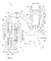
Figs 1 and 2 anapparatus 1 for mixing and pumping is shown. Theapparatus 1 comprises a pump andmixing unit 2 and apiping arrangement 4. The apparatus effects mixing of a liquid L and a material P, where the material P typically is a dry material in powder or granulate form. The mixing may include dissolving the material P in the liquid L, either fully or in part. The material P may also have the form of a liquid with significantly higher viscosity than the liquid L to mix with. The pump andmixing unit 2 also effects pumping of the liquid L and material P prior they are mixed as well as pumping of the liquid L and material P after they have been mixed. When the liquid L and material P have been mixed, they are pumped in combination in the form of a mixture M1, M2. Thepiping arrangement 4 is connected to the pump andmixing unit 2 and ensures that liquid L and material P are effectively fed to the pump andmixing unit 2. In its most basic form the apparatus comprises the pump andmixing unit 2 and thepiping arrangement 4, but may, as will be described, include additional components. - The pump and
mixing unit 2 has aninlet 201 where both liquid L and material P are received. The liquid L and the material P are mixed in the pump andmixing unit 2 and a part M1 of the resulting mixture is expelled via anoutlet 202, while, in one embodiment, another part M2 of the resulting mixture is expelled via afurther outlet 203. The part M1 of the mixture expelled via theoutlet 202 is referred to a "the process mixture" M1, while the other part M2 of the mixture is referred to as a "return mixture" M2. Typically, a flow of process mixture M1 that is expelled via theoutlet 202 is twice as big as a flow of return mixture M2 that is expelled via thefurther outlet 203. In the illustrated embodiment the pump andmixing unit 2 comprises both theoutlet 202 and thefurther outlet 203. Theoutlet 202 may be referred to as a first outlet and thefurther outlet 203 may be referred to as a second outlet. - The
piping arrangement 4 comprises amaterial conduit 412 and aliquid conduit 411 that are joined at a joiningsection 404. In the shown embodiment this joining has been accomplished by connecting thematerial conduit 412 to anupper side 426 of theliquid conduit 411. Theliquid conduit 411 has aninlet 401 for the liquid L and thematerial conduit 412 has aninlet 402 for the material P. The liquid L and the material P are brought together at the joiningsection 404 and are transported to anoutlet 403 of thepiping arrangement 4, whichoutlet 403 is connected to theinlet 201 of the pump andmixing unit 2. Even though the liquid L and the material P are brought together at the joiningsection 404 they are not considered to be mixed here, since bringing them together at the joiningsection 404 typically does not fulfill conventional requirements for adequate mixing. Thus, adequate mixing must be performed, which for the described embodiment is accomplished by the pump andmixing unit 2. - The
piping arrangement 4 also comprises areturn conduit 413 that is connected to thefurther outlet 203 and to thematerial conduit 412. Thereturn conduit 413 conveys the return mixture M2 from thefurther outlet 203 and to thematerial conduit 412. Thus, the return mixture M2 is, together with the material P, brought together with the liquid L at the joiningsection 404 and is thereafter introduced in the pump andmixing unit 2 via theinlet 201. As will be described, the return mixture M2 effectively assists in feeding the material P to the joiningsection 404 as well as assists in feeding the liquid L and the material P to theinlet 201. - The pump and
mixing unit 2 accomplishes mixing primarily by ashear rotor 60 and astator 70 that is arranged about theshear rotor 60. Pumping is accomplished primarily by animpeller 50. However, depending on how theshear rotor 60 is embodied, it may assist more or less in the pumping. Correspondingly, theimpeller 50 may assist in the mixing. Theshear rotor 60, thestator 70 and theimpeller 50 are arranged in the pump andmixing unit 2. In detail, the pump andmixing unit 2 comprises ahousing 220 in which theshear rotor 60, thestator 70 and theimpeller 50 are arranged. Typically, thehousing 220 comprises theinlet 201 for the liquid L and material P, theoutlet 202 for the process mixture M1, and thefurther outlet 203 for the return mixture M2. Theliquid conduit 411 has a horizontal extension such that it may convey the liquid L a horizontal direction x towards theinlet 201 of thehousing 220. Thematerial conduit 412 has a vertical extension such it may convey the material P in a vertical direction y towards theliquid conduit 411. - Both the
shear rotor 60 and theimpeller 50 are rotatable arranged about a geometrical, central axis A1 and are connected to a horizontally arrangeddrive axle 31 that in turn is connected to adrive unit 3. The central axis A1 extends in a horizontal direction and defines a radial direction R. Thedrive unit 3 may have the form of e.g. a conventional, electrical motor. The pump andmixing unit 2 has aconventional gasket 33 arranged about thedrive axle 31 at a location where it extends into the pump andmixing unit 2, such that leakage from the pump andmixing unit 2 is prevented. When thedrive unit 3 is operated thedrive axle 31, theshear rotor 60 and theimpeller 50 rotates with the same rotational speed. Acover 32 is arranged about thedrive axle 31 for preventing that thedrive axle 31 is touched by e.g. an operator. Thecover 32 also acts as a support that connects the pump andmixing unit 2 to thedrive unit 3. - A
hopper 5 is connected to theinlet 402 of thematerial conduit 412 for feeding the material P into thematerial conduit 412. A table 51 may be arranged adjacent thehopper 5 for e.g. more convenient handling material P that shall be fed into thehopper 5. Each of thedrive axle 31, thedrive unit 3 and thehopper 5 may be seen as comprised in theapparatus 1 for mixing and pumping. - A first
manual valve 505 is arranged between thematerial conduit 412 and thehopper 5, which allows an operator to stop a flow of material P into thematerial conduit 412. A secondmanual valve 506 is connected to theinlet 401 of theliquid conduit 411. Typically, liquid L is introduced into thepiping arrangement 4 by connecting a source of liquid (not shown) to the secondmanual valve 506. The secondmanual valve 506 allows an operator to e.g. stop a flow of liquid L into theliquid conduit 411, or to prevent that liquid L flows out from thepiping arrangement 4 when a source of liquid is disconnected from the secondmanual valve 506. - With reference to
Fig. 3 an enlarged, cross-sectional view theapparatus 1 is illustrated. The pump andmixing unit 2 comprise thehousing 220, which in turn comprises, as seen in a horizontal direction x, afront section 221, a firstintermediate section 222, a secondintermediate section 223, animpeller section 224 and abacksection 225. Of course, two or more of these sections 221-225 may be embodied as one, unitary section. The sections 221-225 are attached to each other, e.g. by welding them together or by using conventional bolts that extend from thefrontsection 221 to thebacksection 225 and hold the sections 221-225 together. In the illustrated embodiment, theimpeller section 224 comprises theoutlet 202 for the process mixture M1 and thefurther outlet 203 for the return mixture M2. - The
further outlet 203 is embodied as an opening in theimpeller section 224. Theimpeller section 224 comprises a corresponding opening for theoutlet 202. The opening for theoutlet 202 may not bee seen inFig. 3 since it is arranged on the "backside" the cross-sectional view ofFig. 3 . However, it is possible to arrange the opening for theoutlet 202 directly opposite thefurther outlet 203 or at some other location in theimpeller section 224. - The sections 221-225 form an interior space of the pump and
mixing unit 2 and are, apart from theoutlet 202 and thefurther outlet 203, symmetrical about the central axis A1. Thestator 70, theshear rotor 60 and theimpeller 50 are arranged in the interior space formed by the sections 221-225 and are symmetrically arranged about the central axis A1. - With further reference to
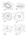
Figs 5 and 6 thestator 70 is shown in detail. As may be seen, thestator 70 has the shape of a circular collar with an inner diameter D1. A number ofopenings 72 are evenly arranged in thestator 70 and thestator 70 is attached to afrontplate 226 of thefrontsection 221. Theopenings 72 are embodied as elongated openings in thestator 70, but may also have the form of slits or cut-outs in thestator 70, typically on the side of thestator 70 that faces away from thefrontsection 221. - With further reference to
Figs 7 and 8 theshear rotor 60 is shown in detail. Theshear rotor 60 comprises acircular plate 63 with acentre hole 66 into which thedrive axle 31 extends (seeFig. 2 ). Theshear rotor 60 may be locked to thedrive axle 31 by e.g. a small key (not shown) or by any other suitable means. At aperiphery 61 of the plate 63 a number ofteeth 62 are arranged. When theshear rotor 60 is arranged in the pump andmixing unit 2, theteeth 62 extends from theplate 63 in a direction towards theinlet 201, parallel to the central axis A1. As may be seen from the figures, theteeth 62 are separated byopenings 65. Theopenings 65 have the form ofinterspaces 65 between theteeth 62. Theshear rotor 60 is symmetrically arranged about the central axis A1 and theplate 63 of the shear rotor has a diameter D2 that is smaller then the inner diameter D1 of thestator 70. Theteeth 62 of theshear rotor 60 are, as seen in the radial direction R, aligned with the stator 70 (seeFig. 3 ). Thus, anannular clearance 71 is formed between thestator 70 and theshear rotor 60, which allows theshear rotor 60 to rotate and liquid to pass through theinterspaces 65, past theannular clearance 71 and through theopenings 72 in thestator 70. When liquid L and material P pass between theinterspaces 65 of theshear rotor 60 and theopenings 72 of thestator 70 shear forces act on the material P in the liquid L, which effectively provides adequate mixing of the liquid L and material P. When the liquid L and the material P has passed theannular clearance 71 and thestator 70 they are conveyed through the pump andmixing unit 2 as a mixture M1, M2. - Instead of arranging
teeth 62 that are separated byinterspaces 65, a collar with openings (e.g. similar to the stator) may be arranged on theplate 63 of theshear rotor 60. However, the outer diameter D2 of theshear rotor 60 must always be smaller then the inner diameter D1 of thestator 70, such that theannular clearance 71 has a radial extension of that may be calculated as D1-D2. - With further reference to
Figs 9 and10 theimpeller 50 is shown in detail. Theimpeller 50 comprises aplate 53 with a number ofvanes 52. On thevanes 52curved ridges 55 are arranged, such that each vane has a respective curved ridge. Theimpeller 50 is symmetrical about acentre hole 54 through which thedrive axle 31 extends (seeFig. 2 ). Theimpeller 50 may be locked to thedrive axle 31 by e.g. a small key (not shown) or by any other suitable means. When theimpeller 50 is arranged in the pump andmixing unit 2, thecurved ridges 55 protrudes from theplate 53 an in a direction towards theinlet 201. Theimpeller 50 is, as seen in the direction towards theinlet 201, arranged behind theshear rotor 60 andstator 70, i.e. theshear rotor 60 and thestator 70 are arranged intermediate theinlet 201 and theimpeller 50. Theimpeller 50 is symmetrical about the central axis A1 and performs the same function as an impeller in a conventional centrifugal pump. - Turning back to
Fig. 3 , thehousing 220 of the pump andmixing unit 2 comprises a firstperipheral chamber 231 that is, as seen in the radial direction R, located outside thestator 70. The firstintermediate section 222 has basically the form of a ring and allows fluid to flow from the first peripheral,annular chamber 231 and in a direction towards the central axis A1 and to anannular passage 232 in theimpeller section 224. Thepassage 232 is located near to the central axis A1 such that the mixture M1, M2 that passes thepassage 232 comes into contact with thecurved ridges 55 of theimpeller 50 at a location close to thecentre hole 54 of theimpeller 50. Then, by rotating theimpeller 50, a flow of mixture M1, M2 is generated since mixture M1, M2 entering theimpeller 50 near to the central axis A1 is accelerated by theimpeller 50 in an outward, radial direction R towards a second peripheral,annular chamber 233 that is formed by theimpeller section 224 andbacksection 225. - Since the
outlet 202 and thefurther outlet 203 are located at the periphery of theimpeller section 224, mixture M1, M2 that is accelerated by theimpeller 50 exits the pump andmixing unit 2 at theoutlets outlet 202 as the process mixture M1, and where a return part of the mixture M1, M2 is expelled from thefurther outlet 203 as the return mixture M2. - The return mixture M2 is expelled into an
inlet 405 of thereturn conduit 413 and is conveyed, by thereturn conduit 413, to anoutlet 406 of thereturn conduit 413. Theoutlet 406 of thereturn conduit 413 is connected to thematerial conduit 412. In detail, thematerial conduit 412 comprises anouter conduit 425 and aninner conduit 421. Thereturn conduit 413 is connected to theouter conduit 425 and theouter conduit 425 is at a first of its ends connected to theliquid conduit 411. Specifically, theouter conduit 425 is joined to theliquid conduit 411 at the joiningsection 404, at theupper side 426 of theliquid conduit 411. At a second end of theouter conduit 425 theinner conduit 421 is inserted. Theinner conduit 421 is attached to theouter conduit 425 by a threadedring 427 that presses aflange 429 of theinner conduit 421 towards a threadedflange 428 of theouter conduit 425, when the threadedring 427 is screwed onto the threadedflange 428. - The
inner conduit 421 has an outer circumference that is smaller than an inner circumference of theouter conduit 425. Thus, anannular chamber 422 is formed between theouter conduit 425 andinner conduit 421, and the return mixture M2 transported by thereturn conduit 413 is introduced into thechamber 422. Thechamber 422 has anopening 424 in form of an annular slit that is located at anoutlet 423 of theinner conduit 421. Thus, when the return mixture M2 is continuously fed to thechamber 422, the return mixture M2 passes through thechamber 422 and exits thechamber 422 at theopening 424. Material P is introduced into theinlet 402 of thepiping arrangement 4, whichinlet 402 is an inlet of theinner conduit 421. Hence, when material P passes into theinner conduit 421 and further to theoutlet 423 of theinner conduit 421, the material P meets the return mixture M2 where theopening 424 of thechamber 422 meets theoutlet 423 of theinner conduit 421. As a result a kind of venturi effect is obtained, where the return mixture M2 assists in feeding the material P into theliquid conduit 411. This is advantageous in that there is a reduced risk of clogging of material P. - With reference to
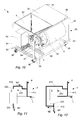
Fig. 10 an alternative embodiment of theapparatus 1 is illustrated. In this embodiment theapparatus 1 is mounted on aframe 80 that comprises a number ofwheels 85. Theapparatus 1, which thus comprises theframe 80 andwheels 85, may then easily be transported and used at a location where it is needed. - The
frame 80 comprises two rectangular frames that are made ofvertical bars 81 andhorizontal bars 82. These frames form two longsides of theframe 80 and are at their lower ends held together by a first set ofhorizontal bars 83 and a second set ofhorizontal bars 84. Thedrive unit 3 is mounted on the second set ofhorizontal bars 84 and thecover 32 that is attached to thedrive unit 3 supports the pump andmixing unit 2. Thehopper 5 and the table 51 are supported by upper sides of the two rectangular frames formed by the vertical andhorizontal bars hopper 5 and the table 51 typically assist in holding theframe 80 together, e.g. by being welded or bolted to theframe 80. Acontrol unit 89 is mounted on theframe 80 and the first set ofhorizontal bars 83. Thecontrol unit 89 is connected to thedrive unit 3 and is arranged to control at least activation, deactivation and a rotational speed of thedrive unit 3. - As may be seen from the figures, the
return conduit 413 is configured to return the return mixture M2 to theinlet 201 without passing the return mixture M2 via any other further pumping equipment. - During operation of the apparatus 1 a source of liquid is connected to the second
manual valve 506, material is fed into thehopper 5 and further past the firstmanual valve 505, and a receptacle or mixture-conveying piping is connected to theoutlet 202. Any suitable source of liquid and receptacle or mixture-conveying piping may be used as long as they may convey liquid to theapparatus 1 respectively receive a mixture from theapparatus 1. However, additional mixing or pumping equipment is not required for achieving adequate mixing and pumping or for ensuring that liquid and material are efficiently fed by theapparatus 1. - Mixing and pumping is performed by the
apparatus 1 alone when thedrive unit 3 is activated and effects a rotation of thedrive axle 31, theimpeller 50 and theshear rotor 60. The rotation of theimpeller 50 generates a suction at theinlet 201 such that the liquid L and the material P is "pulled" into theinlet 201. The liquid L and material P is then pulled further past theshear rotor 60, past theannular clearance 71 and past thestator 70 which effects mixing of the liquid L and material P, such that the liquid L and material P becomes mixed and forms a mixture M1, M2. The mixture M1, M2 is then pulled further towards theimpeller 50 where it is accelerated towards theoutlet 202 and thefurther outlet 203. The part of the mixture M1 that exits via theoutlet 202 is "pushed" or conveyed to a suitable receptacle or mixture-conveying piping, and is referred to as the process mixture M1. The part of the mixture M2 that exits via thefurther outlet 203 is, via thereturn conduit 413, "pushed" or conveyed to thechamber 422, and is referred to as the return mixture M2. The return mixture M2 assists in pulling the material P out from theinner conduit 421 and thereafter assists in pushing the material P as well as liquid L in theliquid conduit 411 towards theinlet 201. The pushing or pulling of liquid and material may also be referred to as "feeding" the liquid and material. - For obtaining a suitable pushing or pulling effect on the liquid L and the material P up to one third of the mixture M1, M2 may be returned as the return mixture M2. Thus, at least two thirds of the mixture M1, M2 is advantageously fed as the process mixture M1. Other embodiments of the
apparatus 1 may require different proportions between the return mixture M2 and process mixture M1, and may be empirically determined for obtaining adequate feeding and mixing. - During operation liquid L is continuously fed into the
liquid conduit 411 and material P is continuously fed into thehopper 5. As a result, material is continuously mixed with liquid that flows in a steady stream, which may referred to as so called inline mixing. - With reference to
Fig. 11 a schematic drawing of the describedapparatus 1 is shown. A second embodiment of theapparatus 1 is schematically illustrated byFig. 12 . The second embodiment differs from the previous one in that thefurther outlet 203 is omitted and in that the return conduit 413' is connected to theoutlet 202 via a connection point that is located downstream theoutlet 202. The connection point may be embodied as conventional flow divider, such that a predetermined part M2 of the mixture enters the return conduit 413' where it is conveyed as the return mixture M2, while a remaining part M1 of the mixture is conveyed by aconduit 419 as the process mixture M1. In this embodiment the return conduit 413' may be seen as comprising a first branch 413' and asecond branch 419, where the first branch 413' conveys a part M2 of the mixture in a direction towards theinlet 201, while thesecond branch 419 conveys a remaining part M1 of the mixture in another direction. - With reference to
Fig. 13 a third embodiment of anapparatus 1 for pumping and mixing is shown. The third embodiment differs from the embodiment ofFigs 1-3 in that areturn conduit 413" is connected from thefurther outlet 203 and directly to theliquid conduit 411. This allows the return mixture M2 to push the liquid L in a direction towards the pump andmixing unit 2. This is, in comparison to not returning any return mixture M2 to theinlet 201, advantageous in that the feeding of the liquid L is improved. Improved feeding of liquid L improves in turn feeding of material P towards the pump andmixing unit 2, since the liquid L draws the material P. - From the description above follows that, although various embodiments of the invention have been described and shown, the invention is not restricted thereto, but may also be embodied in other ways within the scope of the subject-matter defined in the following claims. In particular, the return conduit may be connected in several ways to the pump and mixing unit, as long as it somehow returns the return mixture to the inlet of the pump and mixing unit.
Claims (14)
- An apparatus for mixing and pumping, the apparatus comprising
a housing (220) with an inlet (201) and an outlet (202) for receiving and expelling liquid (L) and a material (P),
a shear rotor (60) rotatably arranged in the housing (220) about a central axis (A1) and connected to a drive unit (3),
a stator (70) fixedly arranged in the housing (220) and surrounding a periphery (61) of the shear rotor (60) such that an annular clearance (71) is formed between the shear rotor (60) and the stator (70), wherein the liquid (L) and material (P) pass the annular clearance (71) and through openings (72) in the stator (70) when the drive unit (3) is activated, thereby effecting mixing of the liquid (L) and material (P), and
an impeller (50) rotatably arranged in the housing (220) about the central axis (A1) and connected to the drive unit (3), such that the impeller (50) pumps the liquid (L) and material from the inlet (201), via the annular clearance (71), via the openings (72) in the stator (70) and to the outlet (202) when the drive unit (3) is activated,
a return conduit (413) configured to return to the inlet (201) a part (M2) of the liquid (L) and material (P) pumped via the annular clearance (71) and the openings (72) in the stator (70), characterized by
a liquid conduit (411) arranged to convey the liquid (L) to the inlet (201), and a material conduit (412) arranged to convey the material (P) to the inlet (201), wherein the return conduit (413) is connected to the material conduit (412), such that a flow of the material (P) in the material conduit (412) is facilitated by the part of the liquid (L) and material (P) returned by the return conduit (413). - An apparatus according to claim 1, wherein the housing (220) comprises a further outlet (203) to which the return conduit (413) is connected for receiving the part of the liquid (L) and material (P) to return to the inlet (201), while a remaining part of the liquid (L) and material (P) is conveyed via the outlet (202).
- An apparatus according to claim 1, wherein the return conduit (413) is connected to the outlet (202) of the housing (220) and comprises
a first branch (413') that conveys the part of the liquid (L) and material (P) in a direction towards the inlet (201), and
a second branch (419) that conveys a remaining part of the liquid (L) and material (P) in another direction. - An apparatus according to any one of claims 1 - 3, wherein the return conduit (413) is configured to return to the inlet (201) less than one third of the liquid (L) and material (P) pumped by the impeller (50).
- An apparatus according to any one of claims 1 - 4, wherein the shear rotor (60) and the impeller (50) are arranged to rotate about a horizontal, geometrical axis (A1).
- An apparatus according to claim 5, comprising a horizontally arranged drive axle (31) that connects the shear rotor (60) and the impeller (50) to the drive unit (3).
- An apparatus according to claim 1, wherein the material conduit (412) comprises an outer conduit (425), an inner conduit (421) and a chamber (422) that is formed between the outer conduit (425) and the inner conduit (421), the inner conduit (421) being arranged to convey the material (P) and the return conduit (413) being connected to the chamber (422) such that the chamber (422) may receive the part of the liquid (L) and material (P) returned by the return conduit (413), the chamber (422) comprising an opening (424) that surrounds at least a part of an outlet (423) of the inner conduit (421), such that the liquid (L) and material (P) returned by the return conduit pass through the opening (424) and come into contact with and thereby transport material (P) from the inner conduit (421).
- An apparatus according to claim 1 or 7, wherein the material conduit (412) is connected to the liquid conduit (411), such that material (P) from the material conduit (412) is conveyed to the inlet (201) via the liquid conduit (411).
- An apparatus according to claim 8, wherein
the liquid conduit (411) has a horizontal extension such that it conveys liquid in a horizontal direction (x) towards the inlet (201) of the housing (220), and
the material conduit (412) has a vertical extension such it conveys material (P) in a vertical direction (y) towards the liquid conduit (411), and is, as seen in the vertical direction (y), connected to an upper side (426) of the liquid conduit (411). - An apparatus according to any one of claims 1 and 7 - 9, wherein the material conduit (412) comprises a first manual valve (505) and the liquid conduit (411) comprises a second manual valve (506).
- An apparatus according to any one of claims 1 - 10, wherein the apparatus is mounted on a frame (80) that comprises a number of wheels (85) for transporting the apparatus.
- An apparatus according to any one of claims 1 and 7 - 11, comprising
a hopper (5) that is connected to the material conduit (412), and
a table (51) arranged adjacent the hopper (5). - An apparatus according to claim 11 and 12, wherein the hopper (5) and the table (51) are supported by the frame (80).
- An apparatus according to any one of claims 1 - 13, wherein the return conduit (413) is configured to return the part of the liquid (L) and material (P) to the inlet (201) without passing the returned part of the liquid (L) and material (P) via any further pumping equipment.
Priority Applications (4)
| Application Number | Priority Date | Filing Date | Title |
|---|---|---|---|
| EP11188174.4A EP2574396B1 (en) | 2011-09-30 | 2011-11-08 | Apparatus for mixing and pumping |
| CN201280058811.6A CN103958039B (en) | 2011-09-30 | 2012-09-24 | For mixing and the equipment of pumping |
| PCT/EP2012/068742 WO2013045381A1 (en) | 2011-09-30 | 2012-09-24 | Apparatus for mixing and pumping |
| US14/348,333 US9833756B2 (en) | 2011-09-30 | 2012-09-24 | Apparatus for mixing and pumping |
Applications Claiming Priority (2)
| Application Number | Priority Date | Filing Date | Title |
|---|---|---|---|
| EP11183495 | 2011-09-30 | ||
| EP11188174.4A EP2574396B1 (en) | 2011-09-30 | 2011-11-08 | Apparatus for mixing and pumping |
Publications (2)
| Publication Number | Publication Date |
|---|---|
| EP2574396A1 EP2574396A1 (en) | 2013-04-03 |
| EP2574396B1 true EP2574396B1 (en) | 2014-06-04 |
Family
ID=45747078
Family Applications (1)
| Application Number | Title | Priority Date | Filing Date |
|---|---|---|---|
| EP11188174.4A Active EP2574396B1 (en) | 2011-09-30 | 2011-11-08 | Apparatus for mixing and pumping |
Country Status (5)
| Country | Link |
|---|---|
| US (1) | US9833756B2 (en) |
| EP (1) | EP2574396B1 (en) |
| CN (1) | CN103958039B (en) |
| DK (1) | DK2574396T3 (en) |
| WO (1) | WO2013045381A1 (en) |
Families Citing this family (8)
| Publication number | Priority date | Publication date | Assignee | Title |
|---|---|---|---|---|
| DE102013113275A1 (en) * | 2013-11-29 | 2015-06-03 | Alfred Kärcher Gmbh & Co. Kg | Device for producing CO2 pellets from CO2 snow and cleaning device |
| JP6707779B2 (en) * | 2015-02-13 | 2020-06-10 | 日本スピンドル製造株式会社 | Dispersion method of substance to be treated, dispersion device, and method of producing liquid in which substance to be treated and dispersion medium are mixed |
| GB2536502A (en) * | 2015-03-20 | 2016-09-21 | Silverson Machines Ltd | Apparatus and method for high-shear mixing |
| EP3416217B1 (en) * | 2016-02-08 | 2021-03-17 | National Institute of Advanced Industrial Science and Technology | Non-aqueous electrolyte secondary battery positive electrode slurry production method |
| JP7382318B2 (en) * | 2018-07-05 | 2023-11-16 | 日本スピンドル製造株式会社 | Slurry manufacturing equipment and slurry manufacturing method |
| DE102019102583A1 (en) * | 2019-02-01 | 2020-08-06 | Ystral Gmbh Maschinenbau + Processtechnik | Rotor for a device for mixing powder and liquid and device for mixing powder and liquid |
| CN112169673A (en) * | 2020-10-27 | 2021-01-05 | 罗斯(无锡)设备有限公司 | Solid-liquid dispersion device |
| CN113464112A (en) | 2021-07-30 | 2021-10-01 | 烟台杰瑞石油装备技术有限公司 | Mix row device, mix row system and fracturing system |
Family Cites Families (15)
| Publication number | Priority date | Publication date | Assignee | Title |
|---|---|---|---|---|
| SE420050B (en) | 1980-01-15 | 1981-09-14 | Alfa Laval Ab | DEVICE FOR WEIGHING POWDER AND LIQUID MIXING THE POWDER IN LIQUID |
| US4850704A (en) | 1986-08-28 | 1989-07-25 | Ladish Co. | Two stage blender |
| NL9220017A (en) | 1991-05-28 | 1994-06-01 | Abbott Lab | Device for mixing a powder with a liquid. |
| CN2238678Y (en) * | 1995-06-26 | 1996-10-30 | 宗佩芬 | Clearance adjustable mixing emulsifying device |
| DE19638567A1 (en) * | 1996-09-20 | 1998-03-26 | Bayer Ag | Mixer reactor and process for carrying out reactions, in particular the phosgenation of primary amines |
| DE10204921C1 (en) * | 2002-02-07 | 2003-10-16 | Romaco Ag Frymakoruma Rheinfel | Dispersing apparatus |
| DE10320739B3 (en) | 2003-05-09 | 2004-10-21 | Ika - Werke Gmbh & Co. Kg | Device for dispersing and/or homogenizing pumpable material mixtures comprises a pump arranged in the feed direction of the material at a distance from a dispersing and/or homogenizing tool and in front of the opening of a feed line |
| US7048432B2 (en) | 2003-06-19 | 2006-05-23 | Halliburton Energy Services, Inc. | Method and apparatus for hydrating a gel for use in a subterranean formation |
| JP4458536B2 (en) | 2005-03-31 | 2010-04-28 | 株式会社イズミフードマシナリ | Powder mixing pump |
| CN100558463C (en) * | 2006-12-22 | 2009-11-11 | 中国石油化工股份有限公司 | A kind of continuous-blending muller |
| DE102007032228B4 (en) * | 2007-07-11 | 2016-01-07 | Gea Tuchenhagen Gmbh | Self-priming pump aggregation |
| CN100546704C (en) | 2007-12-25 | 2009-10-07 | 上海威泽尔机械设备制造有限公司 | Self-suction batch feeder |
| DE102008045820A1 (en) * | 2008-09-05 | 2010-04-08 | Axel Wittek | Transition elements for passing a dispersion in the treatment in a rotor-stator dispersing machine |
| CN201664587U (en) * | 2009-07-10 | 2010-12-08 | 罗星健 | Sealing-less and speed-reduction sealing high-shear emulsifier |
| US9334471B2 (en) | 2010-05-28 | 2016-05-10 | Gea Brewery Systems Gmbh | Method for accelerated fermentation and device for mixing a tank content |
-
2011
- 2011-11-08 DK DK11188174.4T patent/DK2574396T3/en active
- 2011-11-08 EP EP11188174.4A patent/EP2574396B1/en active Active
-
2012
- 2012-09-24 WO PCT/EP2012/068742 patent/WO2013045381A1/en active Application Filing
- 2012-09-24 US US14/348,333 patent/US9833756B2/en active Active
- 2012-09-24 CN CN201280058811.6A patent/CN103958039B/en active Active
Also Published As
| Publication number | Publication date |
|---|---|
| CN103958039A (en) | 2014-07-30 |
| US20140241108A1 (en) | 2014-08-28 |
| WO2013045381A1 (en) | 2013-04-04 |
| DK2574396T3 (en) | 2014-08-25 |
| EP2574396A1 (en) | 2013-04-03 |
| CN103958039B (en) | 2016-08-17 |
| US9833756B2 (en) | 2017-12-05 |
Similar Documents
| Publication | Publication Date | Title |
|---|---|---|
| EP2574396B1 (en) | Apparatus for mixing and pumping | |
| JP4458536B2 (en) | Powder mixing pump | |
| US20160271575A1 (en) | Apparatus and method for high-shear mixing | |
| US10137420B2 (en) | Mixing apparatus with stator and method | |
| US20240033695A1 (en) | Mixing apparatus with flush line and method | |
| US20110036935A1 (en) | Agitator mill | |
| KR101658410B1 (en) | Dispersing and emulsifying apparatus for high viscosity fluid | |
| CN113499698A (en) | Powder-liquid mixer | |
| CN101832274A (en) | The centrifugal drain pump with blade impellers of dishwasher and similar household electric appliance | |
| EP3641924B1 (en) | Fluid handling apparatus, fluid tank system and method for mixing | |
| US7862493B2 (en) | Centrifuge for continuous separation of flowable substances of different densities having an air extraction member | |
| CN106457178B (en) | Mixing apparatus and method with stator | |
| JP2016059335A (en) | Meat grinder | |
| US10780406B2 (en) | Mixing device with integrated delivery pump | |
| KR20180053303A (en) | Apparatus and method for dispersing at least one material in a fluid | |
| WO2009103256A2 (en) | Sludge reactor pump for simultaneously conveying solids, liquids, vapours and gases | |
| KR101707814B1 (en) | Dispersing and emulsifying apparatus for low viscosity fluid | |
| CN215876933U (en) | Powder-liquid mixer | |
| US20230249139A1 (en) | Jet Propulsion Dry Powder Dissolution Unit That Uses a Submersible Actuator | |
| KR930005872Y1 (en) | Mixer pump | |
| CN101457773A (en) | Uniaxial paralleling centrifugal pump for simultaneously conveying double mediums | |
| CN116116299A (en) | Stirring micromixer and mixing system | |
| EP0882495A1 (en) | Fluid mixing | |
| OA17834A (en) | Mixing apparatus with stator and method | |
| JPH0634183U (en) | Vertical vane pump |
Legal Events
| Date | Code | Title | Description |
|---|---|---|---|
| PUAI | Public reference made under article 153(3) epc to a published international application that has entered the european phase |
Free format text: ORIGINAL CODE: 0009012 |
|
| AK | Designated contracting states |
Kind code of ref document: A1 Designated state(s): AL AT BE BG CH CY CZ DE DK EE ES FI FR GB GR HR HU IE IS IT LI LT LU LV MC MK MT NL NO PL PT RO RS SE SI SK SM TR |
|
| AX | Request for extension of the european patent |
Extension state: BA ME |
|
| 17P | Request for examination filed |
Effective date: 20130919 |
|
| RBV | Designated contracting states (corrected) |
Designated state(s): AL AT BE BG CH CY CZ DE DK EE ES FI FR GB GR HR HU IE IS IT LI LT LU LV MC MK MT NL NO PL PT RO RS SE SI SK SM TR |
|
| GRAP | Despatch of communication of intention to grant a patent |
Free format text: ORIGINAL CODE: EPIDOSNIGR1 |
|
| RIC1 | Information provided on ipc code assigned before grant |
Ipc: B01F 13/00 20060101ALI20140131BHEP Ipc: B01F 3/12 20060101AFI20140131BHEP Ipc: B01F 5/10 20060101ALI20140131BHEP Ipc: B01F 7/02 20060101ALI20140131BHEP Ipc: B01F 7/00 20060101ALI20140131BHEP Ipc: B01F 15/02 20060101ALI20140131BHEP |
|
| INTG | Intention to grant announced |
Effective date: 20140225 |
|
| GRAS | Grant fee paid |
Free format text: ORIGINAL CODE: EPIDOSNIGR3 |
|
| GRAA | (expected) grant |
Free format text: ORIGINAL CODE: 0009210 |
|
| AK | Designated contracting states |
Kind code of ref document: B1 Designated state(s): AL AT BE BG CH CY CZ DE DK EE ES FI FR GB GR HR HU IE IS IT LI LT LU LV MC MK MT NL NO PL PT RO RS SE SI SK SM TR |
|
| REG | Reference to a national code |
Ref country code: GB Ref legal event code: FG4D |
|
| REG | Reference to a national code |
Ref country code: CH Ref legal event code: EP |
|
| REG | Reference to a national code |
Ref country code: AT Ref legal event code: REF Ref document number: 670731 Country of ref document: AT Kind code of ref document: T Effective date: 20140615 |
|
| REG | Reference to a national code |
Ref country code: SE Ref legal event code: TRGR |
|
| REG | Reference to a national code |
Ref country code: IE Ref legal event code: FG4D |
|
| REG | Reference to a national code |
Ref country code: DE Ref legal event code: R096 Ref document number: 602011007389 Country of ref document: DE Effective date: 20140717 |
|
| REG | Reference to a national code |
Ref country code: DK Ref legal event code: T3 Effective date: 20140818 |
|
| REG | Reference to a national code |
Ref country code: AT Ref legal event code: MK05 Ref document number: 670731 Country of ref document: AT Kind code of ref document: T Effective date: 20140604 |
|
| REG | Reference to a national code |
Ref country code: NL Ref legal event code: VDEP Effective date: 20140604 |
|
| PG25 | Lapsed in a contracting state [announced via postgrant information from national office to epo] |
Ref country code: NO Free format text: LAPSE BECAUSE OF FAILURE TO SUBMIT A TRANSLATION OF THE DESCRIPTION OR TO PAY THE FEE WITHIN THE PRESCRIBED TIME-LIMIT Effective date: 20140904 Ref country code: CY Free format text: LAPSE BECAUSE OF FAILURE TO SUBMIT A TRANSLATION OF THE DESCRIPTION OR TO PAY THE FEE WITHIN THE PRESCRIBED TIME-LIMIT Effective date: 20140604 Ref country code: FI Free format text: LAPSE BECAUSE OF FAILURE TO SUBMIT A TRANSLATION OF THE DESCRIPTION OR TO PAY THE FEE WITHIN THE PRESCRIBED TIME-LIMIT Effective date: 20140604 Ref country code: LT Free format text: LAPSE BECAUSE OF FAILURE TO SUBMIT A TRANSLATION OF THE DESCRIPTION OR TO PAY THE FEE WITHIN THE PRESCRIBED TIME-LIMIT Effective date: 20140604 Ref country code: GR Free format text: LAPSE BECAUSE OF FAILURE TO SUBMIT A TRANSLATION OF THE DESCRIPTION OR TO PAY THE FEE WITHIN THE PRESCRIBED TIME-LIMIT Effective date: 20140905 |
|
| REG | Reference to a national code |
Ref country code: LT Ref legal event code: MG4D |
|
| PG25 | Lapsed in a contracting state [announced via postgrant information from national office to epo] |
Ref country code: HR Free format text: LAPSE BECAUSE OF FAILURE TO SUBMIT A TRANSLATION OF THE DESCRIPTION OR TO PAY THE FEE WITHIN THE PRESCRIBED TIME-LIMIT Effective date: 20140604 Ref country code: AT Free format text: LAPSE BECAUSE OF FAILURE TO SUBMIT A TRANSLATION OF THE DESCRIPTION OR TO PAY THE FEE WITHIN THE PRESCRIBED TIME-LIMIT Effective date: 20140604 Ref country code: RS Free format text: LAPSE BECAUSE OF FAILURE TO SUBMIT A TRANSLATION OF THE DESCRIPTION OR TO PAY THE FEE WITHIN THE PRESCRIBED TIME-LIMIT Effective date: 20140604 Ref country code: LV Free format text: LAPSE BECAUSE OF FAILURE TO SUBMIT A TRANSLATION OF THE DESCRIPTION OR TO PAY THE FEE WITHIN THE PRESCRIBED TIME-LIMIT Effective date: 20140604 |
|
| PG25 | Lapsed in a contracting state [announced via postgrant information from national office to epo] |
Ref country code: ES Free format text: LAPSE BECAUSE OF FAILURE TO SUBMIT A TRANSLATION OF THE DESCRIPTION OR TO PAY THE FEE WITHIN THE PRESCRIBED TIME-LIMIT Effective date: 20140604 Ref country code: PT Free format text: LAPSE BECAUSE OF FAILURE TO SUBMIT A TRANSLATION OF THE DESCRIPTION OR TO PAY THE FEE WITHIN THE PRESCRIBED TIME-LIMIT Effective date: 20141006 Ref country code: SK Free format text: LAPSE BECAUSE OF FAILURE TO SUBMIT A TRANSLATION OF THE DESCRIPTION OR TO PAY THE FEE WITHIN THE PRESCRIBED TIME-LIMIT Effective date: 20140604 Ref country code: EE Free format text: LAPSE BECAUSE OF FAILURE TO SUBMIT A TRANSLATION OF THE DESCRIPTION OR TO PAY THE FEE WITHIN THE PRESCRIBED TIME-LIMIT Effective date: 20140604 Ref country code: RO Free format text: LAPSE BECAUSE OF FAILURE TO SUBMIT A TRANSLATION OF THE DESCRIPTION OR TO PAY THE FEE WITHIN THE PRESCRIBED TIME-LIMIT Effective date: 20140604 Ref country code: CZ Free format text: LAPSE BECAUSE OF FAILURE TO SUBMIT A TRANSLATION OF THE DESCRIPTION OR TO PAY THE FEE WITHIN THE PRESCRIBED TIME-LIMIT Effective date: 20140604 |
|
| PG25 | Lapsed in a contracting state [announced via postgrant information from national office to epo] |
Ref country code: IS Free format text: LAPSE BECAUSE OF FAILURE TO SUBMIT A TRANSLATION OF THE DESCRIPTION OR TO PAY THE FEE WITHIN THE PRESCRIBED TIME-LIMIT Effective date: 20141004 Ref country code: PL Free format text: LAPSE BECAUSE OF FAILURE TO SUBMIT A TRANSLATION OF THE DESCRIPTION OR TO PAY THE FEE WITHIN THE PRESCRIBED TIME-LIMIT Effective date: 20140604 Ref country code: NL Free format text: LAPSE BECAUSE OF FAILURE TO SUBMIT A TRANSLATION OF THE DESCRIPTION OR TO PAY THE FEE WITHIN THE PRESCRIBED TIME-LIMIT Effective date: 20140604 |
|
| REG | Reference to a national code |
Ref country code: DE Ref legal event code: R097 Ref document number: 602011007389 Country of ref document: DE |
|
| PLBE | No opposition filed within time limit |
Free format text: ORIGINAL CODE: 0009261 |
|
| STAA | Information on the status of an ep patent application or granted ep patent |
Free format text: STATUS: NO OPPOSITION FILED WITHIN TIME LIMIT |
|
| 26N | No opposition filed |
Effective date: 20150305 |
|
| REG | Reference to a national code |
Ref country code: DE Ref legal event code: R097 Ref document number: 602011007389 Country of ref document: DE Effective date: 20150305 |
|
| PG25 | Lapsed in a contracting state [announced via postgrant information from national office to epo] |
Ref country code: LU Free format text: LAPSE BECAUSE OF FAILURE TO SUBMIT A TRANSLATION OF THE DESCRIPTION OR TO PAY THE FEE WITHIN THE PRESCRIBED TIME-LIMIT Effective date: 20141108 Ref country code: MC Free format text: LAPSE BECAUSE OF FAILURE TO SUBMIT A TRANSLATION OF THE DESCRIPTION OR TO PAY THE FEE WITHIN THE PRESCRIBED TIME-LIMIT Effective date: 20140604 Ref country code: BE Free format text: LAPSE BECAUSE OF FAILURE TO SUBMIT A TRANSLATION OF THE DESCRIPTION OR TO PAY THE FEE WITHIN THE PRESCRIBED TIME-LIMIT Effective date: 20140604 |
|
| REG | Reference to a national code |
Ref country code: CH Ref legal event code: PL |
|
| PG25 | Lapsed in a contracting state [announced via postgrant information from national office to epo] |
Ref country code: LI Free format text: LAPSE BECAUSE OF NON-PAYMENT OF DUE FEES Effective date: 20141130 Ref country code: SI Free format text: LAPSE BECAUSE OF FAILURE TO SUBMIT A TRANSLATION OF THE DESCRIPTION OR TO PAY THE FEE WITHIN THE PRESCRIBED TIME-LIMIT Effective date: 20140604 Ref country code: CH Free format text: LAPSE BECAUSE OF NON-PAYMENT OF DUE FEES Effective date: 20141130 |
|
| REG | Reference to a national code |
Ref country code: IE Ref legal event code: MM4A |
|
| REG | Reference to a national code |
Ref country code: FR Ref legal event code: PLFP Year of fee payment: 5 |
|
| PG25 | Lapsed in a contracting state [announced via postgrant information from national office to epo] |
Ref country code: IE Free format text: LAPSE BECAUSE OF NON-PAYMENT OF DUE FEES Effective date: 20141108 |
|
| PG25 | Lapsed in a contracting state [announced via postgrant information from national office to epo] |
Ref country code: SM Free format text: LAPSE BECAUSE OF FAILURE TO SUBMIT A TRANSLATION OF THE DESCRIPTION OR TO PAY THE FEE WITHIN THE PRESCRIBED TIME-LIMIT Effective date: 20140604 |
|
| PG25 | Lapsed in a contracting state [announced via postgrant information from national office to epo] |
Ref country code: BG Free format text: LAPSE BECAUSE OF FAILURE TO SUBMIT A TRANSLATION OF THE DESCRIPTION OR TO PAY THE FEE WITHIN THE PRESCRIBED TIME-LIMIT Effective date: 20140604 |
|
| PG25 | Lapsed in a contracting state [announced via postgrant information from national office to epo] |
Ref country code: TR Free format text: LAPSE BECAUSE OF FAILURE TO SUBMIT A TRANSLATION OF THE DESCRIPTION OR TO PAY THE FEE WITHIN THE PRESCRIBED TIME-LIMIT Effective date: 20140604 Ref country code: MT Free format text: LAPSE BECAUSE OF FAILURE TO SUBMIT A TRANSLATION OF THE DESCRIPTION OR TO PAY THE FEE WITHIN THE PRESCRIBED TIME-LIMIT Effective date: 20140604 Ref country code: HU Free format text: LAPSE BECAUSE OF FAILURE TO SUBMIT A TRANSLATION OF THE DESCRIPTION OR TO PAY THE FEE WITHIN THE PRESCRIBED TIME-LIMIT; INVALID AB INITIO Effective date: 20111108 |
|
| REG | Reference to a national code |
Ref country code: FR Ref legal event code: PLFP Year of fee payment: 6 |
|
| REG | Reference to a national code |
Ref country code: FR Ref legal event code: PLFP Year of fee payment: 7 |
|
| PG25 | Lapsed in a contracting state [announced via postgrant information from national office to epo] |
Ref country code: MK Free format text: LAPSE BECAUSE OF FAILURE TO SUBMIT A TRANSLATION OF THE DESCRIPTION OR TO PAY THE FEE WITHIN THE PRESCRIBED TIME-LIMIT Effective date: 20140604 |
|
| REG | Reference to a national code |
Ref country code: FR Ref legal event code: PLFP Year of fee payment: 8 |
|
| PG25 | Lapsed in a contracting state [announced via postgrant information from national office to epo] |
Ref country code: AL Free format text: LAPSE BECAUSE OF FAILURE TO SUBMIT A TRANSLATION OF THE DESCRIPTION OR TO PAY THE FEE WITHIN THE PRESCRIBED TIME-LIMIT Effective date: 20140604 |
|
| REG | Reference to a national code |
Ref country code: DE Ref legal event code: R079 Ref document number: 602011007389 Country of ref document: DE Free format text: PREVIOUS MAIN CLASS: B01F0003120000 Ipc: B01F0023500000 |
|
| P01 | Opt-out of the competence of the unified patent court (upc) registered |
Effective date: 20230414 |
|
| PGFP | Annual fee paid to national office [announced via postgrant information from national office to epo] |
Ref country code: GB Payment date: 20230914 Year of fee payment: 13 |
|
| PGFP | Annual fee paid to national office [announced via postgrant information from national office to epo] |
Ref country code: SE Payment date: 20230912 Year of fee payment: 13 Ref country code: FR Payment date: 20230911 Year of fee payment: 13 |
|
| PGFP | Annual fee paid to national office [announced via postgrant information from national office to epo] |
Ref country code: IT Payment date: 20231010 Year of fee payment: 13 Ref country code: DK Payment date: 20231116 Year of fee payment: 13 Ref country code: DE Payment date: 20230912 Year of fee payment: 13 |