EP2574033B1 - Print controlling apparatus, image forming apparatus, and method for forming image - Google Patents
Print controlling apparatus, image forming apparatus, and method for forming image Download PDFInfo
- Publication number
- EP2574033B1 EP2574033B1 EP12185521.7A EP12185521A EP2574033B1 EP 2574033 B1 EP2574033 B1 EP 2574033B1 EP 12185521 A EP12185521 A EP 12185521A EP 2574033 B1 EP2574033 B1 EP 2574033B1
- Authority
- EP
- European Patent Office
- Prior art keywords
- image
- graphical
- unit
- print data
- graphical primitives
- Prior art date
- Legal status (The legal status is an assumption and is not a legal conclusion. Google has not performed a legal analysis and makes no representation as to the accuracy of the status listed.)
- Active
Links
Images


Classifications
-
- G—PHYSICS
- G06—COMPUTING; CALCULATING OR COUNTING
- G06K—GRAPHICAL DATA READING; PRESENTATION OF DATA; RECORD CARRIERS; HANDLING RECORD CARRIERS
- G06K15/00—Arrangements for producing a permanent visual presentation of the output data, e.g. computer output printers
- G06K15/02—Arrangements for producing a permanent visual presentation of the output data, e.g. computer output printers using printers
- G06K15/18—Conditioning data for presenting it to the physical printing elements
- G06K15/1848—Generation of the printable image
- G06K15/1849—Generation of the printable image using an intermediate representation, e.g. a list of graphical primitives
-
- G—PHYSICS
- G06—COMPUTING; CALCULATING OR COUNTING
- G06K—GRAPHICAL DATA READING; PRESENTATION OF DATA; RECORD CARRIERS; HANDLING RECORD CARRIERS
- G06K15/00—Arrangements for producing a permanent visual presentation of the output data, e.g. computer output printers
- G06K15/02—Arrangements for producing a permanent visual presentation of the output data, e.g. computer output printers using printers
- G06K15/18—Conditioning data for presenting it to the physical printing elements
- G06K15/1848—Generation of the printable image
- G06K15/1856—Generation of the printable image characterized by its workflow
- G06K15/186—Generation of the printable image characterized by its workflow taking account of feedback from an output condition, e.g. available inks, time constraints
-
- G—PHYSICS
- G06—COMPUTING; CALCULATING OR COUNTING
- G06K—GRAPHICAL DATA READING; PRESENTATION OF DATA; RECORD CARRIERS; HANDLING RECORD CARRIERS
- G06K15/00—Arrangements for producing a permanent visual presentation of the output data, e.g. computer output printers
- G06K15/02—Arrangements for producing a permanent visual presentation of the output data, e.g. computer output printers using printers
- G06K15/18—Conditioning data for presenting it to the physical printing elements
- G06K15/1848—Generation of the printable image
- G06K15/1856—Generation of the printable image characterized by its workflow
- G06K15/1861—Generation of the printable image characterized by its workflow taking account of a limited available memory space or rasterization time
- G06K15/1864—Generation of the printable image characterized by its workflow taking account of a limited available memory space or rasterization time by reducing the depth of some image elements' definition
-
- G—PHYSICS
- G06—COMPUTING; CALCULATING OR COUNTING
- G06K—GRAPHICAL DATA READING; PRESENTATION OF DATA; RECORD CARRIERS; HANDLING RECORD CARRIERS
- G06K2215/00—Arrangements for producing a permanent visual presentation of the output data
- G06K2215/0082—Architecture adapted for a particular function
Definitions
- Methods and apparatuses consistent with exemplary embodiments relate to a print controlling apparatus, an image forming apparatus, and a method of forming an image, and more particularly, to a print controlling apparatus, an image forming apparatus, and a method of forming an image using draft-printing.
- Modern print controlling apparatus and image forming apparatus have a so-called "draft-print” mode.
- the draft-print mode reduces quality of texts and images, but can save resources such as toner (ink).
- the draft-print technology generates print data for draft- printing in the print controlling apparatus and the image forming apparatus
- the print data may be expressed in a metafile format or a page description language (PDL).
- Microsoft enhanced metafile (EMF) is the representative of the print data of the metafile format.
- PostScript and PCL are examples of the PDL.
- a PDF format which is intended to describe an original printing page, may be used as metafiles of various formats according to various operating systems.
- the PDL and the metafile of various formats include a record (referred to as a "tag” or “command”) indicating text data, bitmap image data, and vector graphics data.
- the printing page is changed by means of each metafile or PDL record (command).
- a printing process may be controlled in the draft print mode.
- a related-art technology is based on selective data pre-processing according to a type of data.
- U.S. Patent Application Publication No. 20100214614 describes "contextual rendering" of "print elements”. Similar approaches are described in U.S. Patent Application Publication Nos. 20100128287 , 20050063749 , and 20090290883 .
- US 2009/0237681 A1 describes methods, systems and software for embedding and using rendering hints in a bitmap image.
- Print objects are determined by an application.
- internal objects are formed, and rendering hints are assigned to each internal object.
- These rendering hints are embedded in the output bitmap image without increasing its size by reusing selected bit planes. Output quality is maintained by reusing the least significant bit planes and then masking those planes during the output device (firm-ware) RIP process.
- the draft-printing method is based on reduction in density of elements for expressing an image, which results in deterioration in image quality.
- Such related-art methods may cause great waste of toner since these methods paint images on a pixel area basis.
- the sketch image refers to an image that looks like a picture drawn with a pencil. If draft printing is performed using the sketch image, visual quality of the original image is improved and sense of reality is not reduced so much.
- vector-based composite graphics may cause problems in an application of independent image printing rules, and also, a similar problem arises when one tries to convert such composite graphics into a sketch image.
- the conversion into the sketch image is not applied to a primitive represented by a small rasterized image, that is, a line with one pixel width. That is, since the conversion into the sketch image is applied to only the whole picture, there is a demand for a method for combining graphical primitives into a group in order to generate a picture with the graphical primitives.
- One or more exemplary embodiments provide a print controlling apparatus, an image forming apparatus, and a method forming an image by performing draft-printing.
- One or more exemplary embodiments also provide a print controlling apparatus, an image forming apparatus, and a method of forming an image, which support draft-printing with improved visibility, so that visibility of a draft-printed picture can be maintained and also toner (ink) can be saved.
- FIGS. 1A and 1B are views illustrating an example of a bitmap image (a) as a typical original picture and an example of a result (b) of converting the bitmap image into a sketch image according an exemplary embodiment of the present general inventive concept.
- the term "sketch” may designate an image that looks like an edge drawn with a pencil, which is separated from an original picture as illustrated in FIG. 1 showing a typical original picture and a sketch of the original picture.
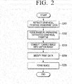
- FIG. 2 is a flowchart illustrating an image forming method according to an exemplary embodiment of the present general inventive concept.
- the image forming method includes extracting one or more graphical primitives from print data at operation S201 and forming an image by arranging the one or more graphical primitives according to a determination of whether the extracted graphical primitives are disposed close to each other at operation S202.
- the formed image is converted into a sketch image at operation S203.
- the print data is modified by replacing the sketch image and some of the graphical primitives constituting the sketch image at operation S204. Draft printing is performed using the modified print data to form an image at operation S205.
- the extracting the one or more graphical primitives at operation S201 may include identifying the one or more graphical primitives included in the print data by examining a metafile or a PDL record of the print data.
- the identified one or more graphical primitives are extracted from the print data for an additional process to be performed at operation S202.
- the extracted graphical primitive may be represented by a vector graphical element and/or a bitmap image.
- the forming the image by arranging the one or more graphical primitives at operation S202 includes generating the image by arranging the one or more graphical primitives based on geometrical vicinity between the extracted graphical primitives.
- the forming the image at operation S202 is performed according to a 'geometrical analysis' on one or more relationships between the one or more graphical primitives.
- This operation may be performed according to a possibility that graphical primitive groups continuously generate a sketch image for a whole image. However, the grouping of the graphical primitives may not result in separation of elements of graphics.
- the extracted graphical primitives are grouped and combined into the image.
- the image formed by grouping the graphical primitives is converted into a sketch image.
- the converting the image at operation S203 includes converting the formed image into a sketch image. That is, the converting method is performed by generating an auxiliary bitmap. The image composed of the graphical primitive groups is converted into a bitmap image.
- the sketch image is generated based on the bitmap image. All suitable algorithms applied hereto at this time may determine a line of an image in which contrasting junctions exist, and an algorithm to suppress a monotone color area may be applied.
- the generated sketch image is stored in a metafile which describes the print data (or a page description language) as a new record. That is, the print data is modified by deleting a portion of an original record which describes the graphical primitives combined into the image. At this time, the record of the graphical primitives combined into the image is replaced with a record of the generated sketch image. An incomplete portion of the original image may be deleted if it is necessary to partially maintain the original graphical primitives. For example, those which are used to determine a border framework of the image are maintained.
- the printing operation is performed using the modified print data at operation S205.
- the image forming method may further include processing a print spool file.
- a print page may be formed by an individual print job and may be represented by a metafile (an EMF format in the Window OS).
- a metafile an EMF format in the Window OS.
- One metafile exists in every page of a document to be printed and the image forming method according to the present disclosure may be applied to every page.
- a sketch image may be generated for every page of the print document to perform draft printing.
- the image forming method according to the present disclosure may be applied to a metafile of a different format, for example, a PDF file, and also, may be extended to metafiles of other formats.
- FIG. 3 is a block diagram illustrating a process of modifying an initial print job according to an exemplary embodiment of the present general inventive concept.
- an initial print job is modified according to a print job modifying process.
- the modified print job is a print job to be performed using print data modified according to the image forming method illustrated in FIG. 2 .
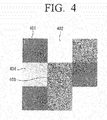
- FIG. 4 is a view illustrating a case where graphical primitives of colored rectangles without borders cannot be separately sketched.
- the graphical primitives are filled with different colors, but have no border. That is, it can be seen that the graphical primitives are composed of rectangles of different colors without borders that make the image clearer. It is possible that each graphical primitive cannot be separately sketched. That is, the graphical primitives can be sketched only as a whole image. That is, if the graphical primitives are filled with colors without color frames as illustrated in FIG. 4 , the graphical primitives can be sketched only as a whole image.
- FIG. 4 illustrates areas 401 to 404 as rectangles that are filled with different colors.
- the graphical primitives illustrated in FIG. 4 can be sketched only as a whole image. In other words, if inner colors are removed, the whole image disappears. It is impossible to generate a colored grid which is a goal of the generation of the sketch image.
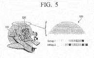
- FIG. 5 is a view illustrating a case where graphical primitives composed of a primitive bitmap set which includes pixels in one row cannot be separately sketched.
- a single line of pixels constituting an image expresses an image that is composed of a combination of small capacity rasterized bitmaps. That is, each line may be represented by each record in a metafile. The whole image is necessary for sketch, but a random metafile record is not necessary to understand the whole image clearly. That is, the row of these pixels cannot be sketched separately.
- the operation of converting the image into the sketch image may be applied to the whole image.
- the conversion into the sketch image may not be applied to individual graphical primitives.
- the individual primitives can be represented by the bitmap image, but this may be selectively applied. Therefore, it is necessary to group the graphical primitives to form the image.
- image may refer to a combination of 2D graphical elements (dots, spots, lines, and shapes) which are visually perceived by human's eyes as a whole.
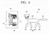
- FIG. 6 is a view illustrating image determination according to visual perception.
- FIG. 6 illustrates an image (a) of a print page which includes 4 pictures according to perception by humans' eyes.
- the print page (a) only two pictures 601 are bitmap images, whereas the other two images 602 are vector graphics composed of separate graphical primitives-lines and elemental shapes.
- FIG. 6 illustrates an image (b) including a plurality of separate graphical elements 621 to 627 which are located slightly away from one another.
- the picture of the image (b) is perceived by human's eyes, existence of the plurality of graphical elements is perceived as a single picture. That is, the human's eyes can naturally group the scattered graphical elements 621 to 627 into the image.
- integrity (integrating) of graphical elements of an image is a key function for grouping the graphical elements.
- the main feature of the geometrical primitives grouping of the present disclosure is grouping individual graphical elements based on geometrical vicinity. If the primitives overlap one another or are disposed close to each other, the graphical primitives may be grouped into the image.
- the graphical primitives may be provided with a description in the form of geometrical parameters according to the present embodiment of the present general inventive concept.
- a description can be arbitrary, but it may include at least geometrical coordinates of the elements which enable calculation of localization on a plane.
- Such geometrical parameters on the bitmap include coordinates of vertices of a rectangular area of the image. From among the vector graphical elements, a radius of a circumference, center coordinates, and coordinates of apexes of a polygon and poly-lines should be calculated. That is, the geometrical coordinates may be expressed in any measurement unit (meters, millimeters, or pixels).
- the pixels may be used as a measurement unit of the geometrical coordinates of the graphical primitives.
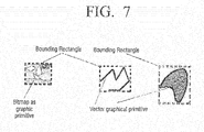
- FIG. 7 is a view illustrating localization areas for graphical primitives according to an exemplary embodiment of the present general inventive concept.
- bounding rectangles of a bitmap image as a graphical primitive (on the left drawing of FIG. 7 ) and vector graphical primitives (on the center and right drawings of FIG. 7 ) are defined as localization areas.
- a bounding area is defined by bounding the graphical primitive.
- this bounding area may be represented by a bounding rectangle or a bounding box.
- these bounding areas may be used to compare the graphical primitives with one another. It is possible that any other polygon may be used to define such a bounding area.
- the bounding rectangle is illustrated as an exemplary shape since it requires the simplest numerical value for geometrical operations, and thus it will be mainly described.
- the graphical primitives which are grouped into the image, are configured so that the bounding areas overlap one another or are disposed close to one another.
- the following rules may be applied according to an exemplary embodiment.
- the pair of graphical primitives may be regarded as overlapping each other.
- the allowable distance may be set separately for each of the two coordinates and may be calculated from a side surface of the rectangle. It is analyzed whether the two bounding rectangles overlap each other on a plane. This analysis is an analysis of geometrical vicinity.
- the process of combining the graphical primitives according to the vicinity of the bounding areas of the graphical primitives in this way is an iterative process.
- the graphical primitives are gathered in a specific group and the gathered groups are gathered in a larger group.
- the two graphical primitives overlap each other and bounding rectangles 1 and 2 including the two graphical primitives are combined with each other by one iteration so that one bounding rectangle is formed (illustrated by dotted lines).
- the two graphical primitives are disposed close to each other within a predetermined distance, and bounding rectangles 1 and 2 including the two graphical primitives are combined with each other by one iteration so that one bounding rectangle is formed (illustrated by dotted lines).
- the graphical primitives are iteratively gathered in the groups in this way so that a bounding rectangle for the whole image is formed.
- the bounding rectangle for the whole picture will be explained with reference to FIGS. 10 and 11 by way of an example.
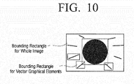
- FIG. 10 is a view illustrating a bounding area for a whole image which is formed by combining graphical primitives according to an exemplary embodiment of the present general inventive concept.
- bounding rectangles for vector graphical elements composed of a circle and straight lines are formed.
- the bounding rectangles for the vector graphical elements may overlap one another. For a certain element from among the vector graphical elements, no bounding rectangle may be formed. From among the straight lines illustrated in FIG. 10 , a line that is not included in a bounding rectangle is illustrated. However, even the straight line that is not included in the bounding rectangle may be included in the bounding rectangle for the whole image. That is, the bounding rectangle for the whole image includes the vector graphical elements included in the bounding rectangles, and the vector graphical element that is not included in the bounding rectangle may be included in the bounding rectangle for the whole picture.
- FIG. 11 Another example of the bounding rectangle for the whole picture (image) is illustrated in FIG. 11 .
- FIG. 11 is a view illustrating a bounding area for a whole image which is formed by combining graphical primitives of the image (b) of FIG. 6 .
- vector graphical elements such as a plurality of ovals, circles, triangles, and circular arcs, are includes in their respective bounding rectangles.
- a number of bounding rectangles overlap one another and certain bounding rectangles are disposed close to one another.
- the bounding rectangles that include vector graphical primitives disposed close to each other within predetermined distances 'tol x' or 'tol y' may be processed as belonging to one group.
- FIG. 12 is a flowchart illustrating a process of grouping graphical primitives using a list of graphical primitives and a list of groups of graphical primitives as initial data.
- Operations of an iterative process of gathering a plurality of graphical primitives in a group based on geometrical vicinity are as follows:
- the grouping operation starts with an operation S1201 of displaying initial data. That is, the initial data is graphical primitives extracted from print data and groups of the graphical primitives, and is displayed as a list of the graphical primitives and a list of the groups of the graphical primitives.
- Iteration of the grouping process starts at operation S1202. That is, the list of the groups of the graphical primitives is blank before the iteration starts and is filled when the grouping process is performed. This will be explained in detail below.
- the graphical primitive is extracted from the primitive list to be compared with those that are included in the list of the groups at operation S1203.
- the list of the groups of the primitives is blank or not at operation S1204. If the group list is blank at operation S1204-Y, the extracted graphical primitive is processed as a first group to be included in the list at operation S1206. Such newly included graphical primitive is only one element that belongs to the group. A border of the graphical primitive included in the group in this way is an initial bounding rectangle of the group.
- this graphical primitive does not belong to any group. In this case, this graphical primitive forms a new group in the group list at operation S1206. At this time, the bounding rectangle forms a bounding rectangle of the new group. In this case, it is determined whether a certain unexamined object exists in the primitive list at operation S1209. If there is an unextracted (or unexamined) object, the iteration of the grouping of the graphical primitives is terminated at operation S1210 and the group list which is not blank is displayed at operation S1211. That is, if all of the primitives existing in the list of the graphical primitives are processed, the iteration is completed. The final results combine the graphical primitives according to the geometrical vicinity, thereby displaying them as the list of the groups of the graphical primitives.
- the primitive should be included in that group.
- the bounding rectangle of the group is modified. That is, the bounding rectangle is re-calculated in order to limit the new primitive included in the group. Accordingly, if the number of groups in the list does not increase, a new element may be added to one of the groups at operation S1206. The next operation is returning to the operation of extracting a next primitive from the list.
- the above-described iteration process may be only a portion (one iteration) of the process of combining the graphical primitives into the image. If the groups overlap each other as a result of the graphical primitives, the groups may be combined into a larger group (see FIG. 13 ). The entire grouping process may include several iterations as described above.
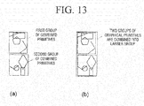
- FIG. 13 is a view illustrating graphical primitives which are combined by iterating the combining process of FIG. 12 .
- FIG. 13 illustrates an image (a) including a first group of primitives combined by a first bounding rectangle, and a second group of primitives combined by a second bounding rectangle.
- FIG. 13 also includes an image (b) to illustrate a case where the first bounding rectangle and the second bounding rectangle are disposed close to each other and thus a single bounding rectangle in which the two groups are combined with each other is formed.
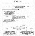
- FIG. 14 is a flowchart illustrating a process of generating an image by arranging graphical primitives according to an exemplary embodiment of the present general inventive concept.
- operations of grouping graphical primitives into an image are as follows: Grouping of all of the graphical primitives provided along with their respective bounding rectangles starts at operation S1401. The process of combining the graphical primitives into groups is iterated at operation S1402. The grouping process of the graphical primitives is iterated one time and a result indicating a list of the groups of the graphical primitives is displayed. A detailed description has been provided above and thus is omitted. That is, the graphical primitives are listed according to the iterating process and are regarded as candidates to be grouped into the image at operation S1403.
- a condition for terminating the grouping process is identified at operation S1404.
- the condition to terminate the grouping process is identified according to a determination of whether the two following rules are met or not.
- new iteration refers to a process of combining previously generated groups at operation S1403 and a new list of the groups is generated at operation S1405.
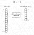
- the total number of groups generated by combining the initial graphical primitives as illustrated in FIG. 15 is reduced. That is, referring to FIG. 15 , the number of objects of initial graphical primitives is reduced as the gathering process is iterated.
- FIG. 15 is a view illustrating a case to reduce a number of graphical primitives by iterating a process of grouping graphical primitives according to an exemplary embodiment of the present general inventive concept.
- the initially extracted graphical primitives include objects 1 to N ob . If the gathering process is iterated one time, the number of objects is reduced to 1 to N gr . Preferably, N ob is greater than N gr . If N ob is equal to N gr , the grouping process is not performed.
- the last group in the graphical primitive list is represented as an image composed of the graphical primitives.
- the image composed of the graphical primitives finally grouped is used to convert an image into a sketch image at operation S1407 of FIG. 14 .
- FIG. 16 is a block diagram illustrating a print controlling apparatus 100 according to an exemplary embodiment of the present general inventive concept.
- the print controlling apparatus 100 includes a user interface unit 110, an extraction unit 120, an image forming unit 130, a sketch image generation unit 140, a print data generation unit 150, and a communication interface unit 160.
- the print controlling apparatus 100 may include a control unit 170 to control components of the print controlling apparatus 100, for example, the user interface unit 110, the extraction unit 120, the image forming unit 130, the sketch image generation unit 140, the print data generation unit 150, and the communication interface unit 160 so that a function of the print controlling apparatus 100 can be performed according to an embodiment of the present general inventive concept.
- the print controlling apparatus 100 may also include a memory unit 180 to store data associated with the function of the print controlling apparatus 100. It is possible that the extraction unit 120, the image forming unit 130, the sketch image generation unit 140, and the print data generation unit 150 are included in the control unit 170 such that the control unit 170 can perform the corresponding functions thereof.
- the user interface unit 110 receives a print command regarding a print job.
- the user interface unit 110 may include a display element to display a user interface to communicate with a user such that a user can input the print command. It is possible that the display element is a touch panel. It is also possible that the user interface unit 110 may include a key or button provided on a main body or housing of the print controlling apparatus 100 to input the print command. It is also possible that the print command can be received from an external device connectable to the print controlling apparatus 100 through a wired or wireless communication method and structure.
- the extraction unit 120 extracts at least one graphical primitive from print data corresponding to the print job.
- the image forming unit 130 forms an image by arranging the graphical primitives according to a determination of whether the extracted graphical primitives are close to each other within a geometrical distance. That is, the image forming unit 130 forms a whole image by grouping the graphical primitives which overlap each other or are disposed close to each other within a predetermined distance. The image forming unit 130 generates an image having the one or more graphical primitives by iterating the grouping of the graphical primitives.
- the image forming unit 130 detects a bounding area of the extracted graphical primitive, and, when the detected bounding areas overlap each other, groups the graphical primitives by combining the graphical primitives in the overlapping bounding areas into the image.
- the image forming unit 130 detects a bounding area of the extracted graphical primitive and determines whether a distance between the bounding areas of the extracted graphical primitives in a coordinate plane or system having at least two coordinates with respect to the image falls within a predetermined distance or not. When the bounding areas overlap each other or the coordinate distance between the bounding areas falls within the predetermined distance, the image forming unit 130 groups the graphical primitives by combining them into the image.
- the sketch image generation unit 140 converts the image formed by the image forming unit 130 into a sketch image.
- the sketch image generation unit 140 includes a rendering unit 141, a color conversion unit 142, a mask generation unit 143, and a multiplication unit 144 as illustrated in FIG. 16A .
- the rendering unit 141 rasterizes the image which is represented by a group of at least one graphical primitive into a bitmap.
- the color conversion unit 142 converts the rasterized bitmap into a monochrome image.
- the mask generation unit 143 detects an edge of the converted monochrome image, and generates a mask.
- the multiplication unit 143 multiplies the bitmap image with the mask, thereby generating the sketch image.
- the print data generation unit 150 modifies the print data by replacing the sketch image and some of the graphical primitives constituting the sketch image.
- the sketch image converting process is performed by directly rasterizing a memory buffer image or an image which is obtained by combining the graphical primitives without being rasterized. That is, the approach without the image rasterization is applied when the image includes vector graphical primitives that do not overlap each other, and also has a border to be clearly represented and a colored inner area. In this case, the color of the inner area is suppressed and the vector element looks like a sketch image in the draft printing by a combination of the graphical elements having the modified border. In general, this approach does not work.
- the temporarily rasterized bitmap is applied in the conversion of each image into a sketch image in such a common and simple method.
- the temporary bitmap may be obtained through a MS-window GDI function and the rasterization is as follows: That is, a "compatible device context” (CDC) and a "compatible raster image” (an internal bitmap of a memory) are prepared for a whole print page (by means of a GDI function). A metafile existing in the CDC is reproduced without text records. Accordingly, the internal bitmap (in an operating memory), which includes graphical elements without text blocks, is obtained.
- the sketch image generation unit 140 directly detects the bounding area of the graphical primitive and suppresses the color of the inside of the bounding area of the graphical primitive.
- An auxiliary memory buffer corresponding to an internal memory bitmap for the whole page is allocated. Size and resolution of the whole page should be considered in estimating a volume of the buffer.
- An image of the whole page is transmitted to the auxiliary buffer from the internal bitmap.
- the buffer localizes the individual image (as a fragment of the whole page bitmap) and transmits the localized segment to an individual local buffer. For the localization of each segment, the coordinates of the bounding rectangle are used in the previous group of the graphical primitives. They correspond to the required boundary of the individual image in the page buffer.
- the local buffer includes the image which is represented as an individual raster image. Such an image is used as the sketch image.
- the sketch image converting process includes the following operations according to the present embodiment.
- the method according to an exemplary embodiment is applicable to both a color and a grayscale image.
- the embodiment of the present general inventive concept includes bitmap image preliminary enhancement, for example, a smoothing operation by a filter, image contrast enhancement, and determination of distinctive visual features of the image, for example, based on an importance map.
- the color bitmap is converted into a grayscale copy. This operation may not be required when an original image is displayed in a grayscale mode.
- An edge is detected for the grayscale image.
- the generated binary mask highlights this edge and suppresses other areas of the image.
- the detection of the edge may be performed by difference of Gaussians (DoG) filtering and introducing a threshold value of the resulting value.
- DoG difference of Gaussians
- the binary mask is applied in the bitmap for the determination of the edge.
- the binary mask is applied to each color channel.
- the mask preserves the image corresponding to only those pixels and the detected edge. As a result of this operation, the image is obtained and is regarded as a sketch.
- the generation of the sketch may be performed based on the preliminary bitmap generated.
- the present general inventive concept is not limited thereto. It is possible that the sketch is generated when the image includes vector graphical elements. In this case, generating the auxiliary bitmap and detecting the edge by filtering may not be required. When it is possible to create usable data, it is enough to suppress the coloring of the inner area of the vector graphical element and to detect the edge. In this case, the result (the sketch) appears as a collection of the graphical primitives along with the modified parameters rather than the sketch. However, this method may be selectively applied.
- the resulting sketch is generated for each of the processed pictures when they are represented as a bitmap data according to the embodiment of the present disclosure.
- Each sketch is used for an output print job as a new graphical primitive instead of the original graphical primitives previously used for generating pictures.
- a new EMF-metafile may be created for this purpose.
- the sketch bitmap is included in the metafile through a corresponding graphic device interface (GDI) command. All of the other records of the input metafile (for example, a text object) are copied to the output printing job (metafile).
- the original graphical primitive used for generating picture and sketches may be excluded from the output metafile (at least a part of the primitive may be excluded).
- some of the primitives for example, horizontal and vertical lines constituting the frame of the table may be optionally saved.
- the print data generation unit 150 generates print data by replacing the bitmap image in the print job using the data converted into the monochrome sketch image.
- the sketch image generated in this way is used for draft-printing.
- the print data generation unit 150 may modify the print data in part by including the original graphical primitive, which is represented by the horizontal and vertical lines, in the modified print data.
- the communication interface unit 160 transmits the modified print data to an image forming apparatus.
- the optional suppression is possible for the text and the graphic records of the modified print job.
- the modified print job is rasterized and is transmitted to the image forming apparatus, so that an image forming job is performed.
- the above explanation is about modifying the initial print job by the print controlling apparatus 100.
- a print controlling apparatus 100 and an image forming apparatus 200 are connected to each other through a wired or wireless communication.
- the print controlling apparatus 100 includes an extraction unit 120, an image generation unit 130, a sketch image generation unit 140, and a print data generation unit 150.
- Initial (input) data is provided as a print job which is represented by a PDL or a metafile.
- the initial data may include records describing text data and graphical primitives.
- the output data is a print job which is modified to perform draft-printing.
- the modified print job is transmitted to the image forming apparatus 200.
- the extraction unit 120 receives the print job and parses the print job into separate records.
- the extraction unit 120 extracts a graphical primitive and transmits the extracted graphical primitive to the image generation unit 130 and the print data generation unit 150.
- the extraction unit 120 extracts all of the other kinds of records and transmits the extracted records to the print data generation unit 150.
- the image generation unit 130 generates an image by arranging the graphical primitives and grouping the graphical primitives according to geometrical vicinity. This is performed according to the above-described method. If limited rectangles of the graphical primitive overlap each other or are disposed close to each other (within a predetermined threshold distance), the graphical primitives are grouped. The image (the groups of the combined graphical primitives) is transmitted to the sketch image generation unit 140, which generates a sketch image.
- the resulting sketch image (represented by the groups of the combined primitives) is transmitted to the image (picture)-to-sketch unit 140 (the sketch image in the present embodiment refers to a bitmap in which the edges are outlined and the inner coloring is suppressed).
- the resulting image is transmitted to the print data generation unit 150.
- the print data generation unit 150 receives all of the records of the initial print job parsed by the extraction unit 120 and/or the sketch image generated by the sketch image generation unit 140.
- the print data generation unit 150 generates a modified print job represented a new metafile including a sketch image as a new bitmap record and/or the record optionally received from the extraction unit 120.
- the print data generation unit 150 optionally suppresses a specific type of a record. Since the sketch image is included in its output metafile, at least a portion of the graphical primitives used previously to generate the sketch image is suppressed. Simultaneously, a portion of the graphical primitives, for example, the horizontal and vertical lines constituting the table grid may be optionally saved.
- the print data generation unit 150 transmits the modified print job to the image forming apparatus 200 through the communication interface unit 160.
- the image forming apparatus 200 may receive the modified print job with the sketch image from an external apparatus and print the received modified print job on a print medium.
- the image forming apparatus 200 may receive the modified print data from the print controlling apparatus 100 through the communication interface unit 160 to print an image corresponding to the modified print data on a print medium. Also, the image forming apparatus 200 may receive print data from the print controlling apparatus 100, modify the received print data, and generate the modified print data for draft-printing.
- the print data transmitted to the image forming apparatus 200 may include additional data or command to indicate whether the print data is a modified print job. According to status of the additional data, the image forming apparatus 200 may determine whether the transmitted print data is an original print data without sketching or a modified print data with sketching. The image forming apparatus 200 may perform either a printing operation to print an image on a print medium as draft-printing or a modifying and printing operation to modify the print data, according to the above-describe method and then print the modified print data according to the above-described determination.
- FIG. 18 is a block diagram illustrating an image forming apparatus 200 according to an exemplary embodiment of the present general inventive concept.
- the image forming apparatus 200 includes an interface unit 210, an extraction unit 220, an image forming unit 230, a sketch image generation unit 240, and a print data generation unit 250.
- the image forming apparatus 200 may include a scan unit 260 to scan a document to generate print data.
- the image forming apparatus 200 may also include a control unit to control the above-described unit to perform a function of the image forming apparatus 200.
- the scan unit 260 may not be included in the image forming apparatus 200. It is possible that the image forming apparatus 200 may be connectable to an external scan unit 260 or an external device to receive the print data corresponding to the scanned document.
- the image forming apparatus 200 may include a control unit 270 to control components of the image forming apparatus 200, for example, the interface unit 210, the extraction unit 220, the image forming unit 230, the sketch image generation unit 240, and the printing unit 250 so that a function of the image forming apparatus 200 can be performed according to an embodiment of the present general inventive concept.
- the image forming apparatus 200 may also include a memory unit 280 to store data associated with the function of the image forming apparatus. it is possible that the extraction unit 220, the image forming unit 230, the sketch image generation unit 240, and at least a portion of the printing unit 250 may be included in the control unit 270 such that the control unit 270 can perform the corresponding functions thereof.
- the interface unit 210 receives print data from the print controlling apparatus 100.
- the interface unit 210 may print data from the scan unit which scans a document and generates the print data corresponding to the scanned document. And the interface unit 210 receives print data from an external print controlling apparatus.
- the extraction unit220 extracts at least one graphical primitive from the print job.
- the image forming unit 230 forms an image by arranging the graphical primitives according to a determination of whether the extracted graphical primitives are disposed close to each other with a geometrical distance. That is, the image forming unit 230 generates a whole image by grouping the graphical primitives which overlap each other or are disposed close to each other within a predetermined distance.
- the image forming unit 230 generates an image having one or more graphical primitives by iterating the grouping of the graphical primitives.
- the image forming unit 230 detects a bounding area of the extracted graphical primitive, and, if the detected bounding areas overlap each other, groups the graphical primitives in the overlapping bounding areas by combining them into the image.
- the image forming unit 230 detects a bounding area of the extracted graphical primitive, determines whether a distance between the bounding areas of the extracted graphical primitives in coordinates falls within a predetermined distance, and, when the bounding areas overlap each other or the coordinate distance between the bounding areas falls within the predetermined distance, groups the graphical primitives by combining them into the image.
- the sketch image generation unit 240 converts the image formed by the image forming unit 230 into a sketch image.
- the sketch image generation unit 240 includes a rendering unit 241, a color conversion unit 242, a mask generation unit 243, and a multiplication unit 244.
- the sketch image generation unit 240 of FIG. 18A is similar to that of the sketch image generation unit 140 of the print controlling apparatus 100 of FIG. 16A described above and thus a detailed description thereof is omitted.
- the printing unit 250 generates print data by replacing a bitmap image in the print job using data which is converted into a monochrome sketch image.
- the sketch image generated in this way is used for draft-printing.
- the printing unit 250 may modify the print data in part by including the original graphical primitives represented by horizontal and vertical lines in the modified print data.
- the methods according to exemplary embodiments of the present disclosure may be applied for an initial printing mode (a toner saving mode) in electrophotographic printers, ink-jet printers and MFP devices, and both monochrome and color ones.
- a toner saving mode a toner saving mode
- the above-described methods may be used in print drivers.
- the methods are applicable to any print jobs represented in a metafile format (for example, EMF, MS-EMFSPOOL) or in a Page Description Language (such as PCL, PS, PDF, XPS) because all these formats contain records ("tags") describing text data, explicit bitmaps and vector graphics.
- a metafile format for example, EMF, MS-EMFSPOOL
- a Page Description Language such as PCL, PS, PDF, XPS
- the present general inventive concept can also be embodied as computer-readable codes on a computer-readable medium.
- the computer-readable medium can include a computer-readable recording medium and a computer-readable transmission medium.
- the computer-readable recording medium is any data storage device that can store data as a program which can be thereafter read by a computer system. Examples of the computer-readable recording medium include read-only memory (ROM), random-access memory (RAM), CD-ROMs, magnetic tapes, floppy disks, and optical data storage devices.
- the computer-readable recording medium can also be distributed over network coupled computer systems so that the computer-readable code is stored and executed in a distributed fashion.
- the computer-readable transmission medium can transmit carrier waves or signals (e.g., wired or wireless data transmission through the Internet). Also, functional programs, codes, and code segments to accomplish the present general inventive concept can be easily construed by programmers skilled in the art to which the present general inventive concept pertains.
Description
- Methods and apparatuses consistent with exemplary embodiments relate to a print controlling apparatus, an image forming apparatus, and a method of forming an image, and more particularly, to a print controlling apparatus, an image forming apparatus, and a method of forming an image using draft-printing.
- Modern print controlling apparatus and image forming apparatus have a so-called "draft-print" mode. The draft-print mode reduces quality of texts and images, but can save resources such as toner (ink). The draft-print technology generates print data for draft- printing in the print controlling apparatus and the image forming apparatus
The print data may be expressed in a metafile format or a page description language (PDL). Microsoft enhanced metafile (EMF) is the representative of the print data of the metafile format. PostScript and PCL are examples of the PDL. A PDF format, which is intended to describe an original printing page, may be used as metafiles of various formats according to various operating systems. - The PDL and the metafile of various formats include a record (referred to as a "tag" or "command") indicating text data, bitmap image data, and vector graphics data. The printing page is changed by means of each metafile or PDL record (command). By this approach, a printing process may be controlled in the draft print mode.
- A related-art technology is based on selective data pre-processing according to a type of data. For example,
U.S. Patent Application Publication No. 20100214614 describes "contextual rendering" of "print elements". Similar approaches are described inU.S. Patent Application Publication Nos. 20100128287 ,20050063749 , and20090290883 . - Another approach is proposed in
U.S. Patent Application Publication No. 20090195811 . This approach configures content-based skipping of objects excluding all of these objects in a printing process. -
US 2009/0237681 A1 describes methods, systems and software for embedding and using rendering hints in a bitmap image. Print objects are determined by an application. In a modified bitmap driver process, internal objects are formed, and rendering hints are assigned to each internal object. These rendering hints are embedded in the output bitmap image without increasing its size by reusing selected bit planes. Output quality is maintained by reusing the least significant bit planes and then masking those planes during the output device (firm-ware) RIP process. - However, there are problems in the related-art technology. In particular, as a rule, the draft-printing method is based on reduction in density of elements for expressing an image, which results in deterioration in image quality. Such related-art methods may cause great waste of toner since these methods paint images on a pixel area basis.
- To solve these problems, draft-printing is performed using a sketch image. The sketch image refers to an image that looks like a picture drawn with a pencil. If draft printing is performed using the sketch image, visual quality of the original image is improved and sense of reality is not reduced so much.
- In order to convert an image into such a sketch image, a picture included in a printing page is expressed by vector graphical elements. These elements are separable. In this case, it is impossible to process a whole image directly.
- That is, in the related-art methods, problems arise if data which looks like a "picture" is represented after being wholly rasterized, being converted into a set of individual graphical elements, or being converted into vector graphical elements. That is, if a picture is represented as a set of independent elements, theses data cannot be processed as an integral picture. Since the data is applied to the picture as a whole rather than as individual elements, most of the toner-saving rules proposed in the above-mentioned patent applications is useless in this case.
- Also, vector-based composite graphics may cause problems in an application of independent image printing rules, and also, a similar problem arises when one tries to convert such composite graphics into a sketch image.
- The conversion into the sketch image is not applied to a primitive represented by a small rasterized image, that is, a line with one pixel width. That is, since the conversion into the sketch image is applied to only the whole picture, there is a demand for a method for combining graphical primitives into a group in order to generate a picture with the graphical primitives.
- One or more exemplary embodiments provide a print controlling apparatus, an image forming apparatus, and a method forming an image by performing draft-printing.
- One or more exemplary embodiments also provide a print controlling apparatus, an image forming apparatus, and a method of forming an image, which support draft-printing with improved visibility, so that visibility of a draft-printed picture can be maintained and also toner (ink) can be saved.
- Additional features and utilities of the present general inventive concept will be set forth in part in the description which follows and, in part, will be obvious from the description, or may be learned by practice of the general inventive concept.
- These and/or other features and utilities of the present general inventive concept will become apparent and more readily appreciated from the following description of the embodiments, taken in conjunction with the accompanying drawings of which:
-
FIGS. 1A and 1B are views illustrating an example of a bitmap image and an example of a result of converting the bitmap image into a sketch image according an exemplary embodiment of the present general inventive concept; -
FIG. 2 is a flowchart illustrating an image forming method according to an exemplary embodiment of the present general inventive concept; -
FIG. 3 is a block diagram schematically illustrating a process of modifying an initial print job by a print controlling apparatus according to an exemplary embodiment of the present general inventive concept; -
FIG. 4 is a view illustrating a case where graphical primitives of colored rectangles without borders cannot be separately sketched; -
FIG. 5 is a view illustrating a case where graphical primitives composed of a primitive bitmap set which includes pixels in one row cannot be separately sketched; -
FIG. 6 is a view illustrating image determination according to visual perception; -
FIG. 7 is a view illustrating examples of localization areas for graphical primitives according to an exemplary embodiment of the present general inventive concept; -
FIG. 8 is a view illustrating a method of forming a new bounding area by combining graphical primitives if localization areas are overlapped with each other according to an exemplary embodiment of the present general inventive concept; -
FIG. 9 is a view illustrating a method of forming a new bounding area by combining graphical primitives if localization areas are located within a threshold distance according to an exemplary embodiment of the present general inventive concept; -
FIG. 10 is a view illustrating a bounding area for a whole image which is formed by combining graphical primitives according to an exemplary embodiment of the present general inventive concept; -
FIG. 11 is a view illustrating a bounding area for a whole image which is formed by combining graphical primitives ofFIG. 6B ; -
FIG. 12 is a flowchart illustrating a process of combining graphical primitives according to an exemplary embodiment of the present general inventive concept; -
FIG. 13 is a view illustrating graphical primitives to be combined by iterating the combining process ofFIG. 12 ; -
FIG. 14 is a flowchart illustrating a process of generating an image by arranging graphical primitives according to an exemplary embodiment of the present general inventive concept; -
FIG. 15 is a view illustrating a method of reducing a number of graphical primitives by iterating a process of grouping graphical primitives according to an exemplary embodiment of the present general inventive concept; -
FIG. 16 is a block diagram illustrating a print controlling apparatus according to another exemplary embodiment of the present general inventive concept; -
FIG. 16A is a view illustrating a sketch image generation unit of the print controlling apparatus ofFIG. 16 ; -
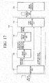
FIG. 17 is a block diagram illustrating the print controlling apparatus ofFIG. 16 in detail; -
FIG. 18 is a block diagram illustrating an image forming apparatus according to an exemplary embodiment of the present general inventive concept; and -
FIG. 18A is a view illustrating a sketch image generation unit of the image forming apparatus ofFIG. 18 . - Reference will now be made in detail to the embodiments of the present general inventive concept, examples of which are illustrated in the accompanying drawings, wherein like reference numerals refer to the like elements throughout. The embodiments are described below in order to explain the present general inventive concept while referring to the figures. The matters defined in the description, such as detailed construction and elements, are provided to assist in a comprehensive understanding of exemplary embodiments. Thus, it is apparent that exemplary embodiments can be carried out without those specifically defined matters. Also, functions or elements known in the related art are not described in detail since they would obscure the exemplary embodiments with unnecessary detail.
-
FIGS. 1A and 1B are views illustrating an example of a bitmap image (a) as a typical original picture and an example of a result (b) of converting the bitmap image into a sketch image according an exemplary embodiment of the present general inventive concept. The term "sketch" may designate an image that looks like an edge drawn with a pencil, which is separated from an original picture as illustrated inFIG. 1 showing a typical original picture and a sketch of the original picture. -
FIG. 2 is a flowchart illustrating an image forming method according to an exemplary embodiment of the present general inventive concept. - Referring to
FIG. 2 , the image forming method according to an exemplary embodiment includes extracting one or more graphical primitives from print data at operation S201 and forming an image by arranging the one or more graphical primitives according to a determination of whether the extracted graphical primitives are disposed close to each other at operation S202. The formed image is converted into a sketch image at operation S203. The print data is modified by replacing the sketch image and some of the graphical primitives constituting the sketch image at operation S204. Draft printing is performed using the modified print data to form an image at operation S205. - The above-described steps will be explained in detail below.
- The extracting the one or more graphical primitives at operation S201may include identifying the one or more graphical primitives included in the print data by examining a metafile or a PDL record of the print data. The identified one or more graphical primitives are extracted from the print data for an additional process to be performed at operation S202. The extracted graphical primitive may be represented by a vector graphical element and/or a bitmap image.
- The forming the image by arranging the one or more graphical primitives at operation S202 includes generating the image by arranging the one or more graphical primitives based on geometrical vicinity between the extracted graphical primitives.
- The forming the image at operation S202 is performed according to a 'geometrical analysis' on one or more relationships between the one or more graphical primitives. This operation may be performed according to a possibility that graphical primitive groups continuously generate a sketch image for a whole image. However, the grouping of the graphical primitives may not result in separation of elements of graphics.
- At the operation S202, the extracted graphical primitives are grouped and combined into the image. The image formed by grouping the graphical primitives is converted into a sketch image.
- The converting the image at operation S203 includes converting the formed image into a sketch image. That is, the converting method is performed by generating an auxiliary bitmap. The image composed of the graphical primitive groups is converted into a bitmap image.
- The sketch image is generated based on the bitmap image. All suitable algorithms applied hereto at this time may determine a line of an image in which contrasting junctions exist, and an algorithm to suppress a monotone color area may be applied.
- At operation S204, the generated sketch image is stored in a metafile which describes the print data (or a page description language) as a new record. That is, the print data is modified by deleting a portion of an original record which describes the graphical primitives combined into the image. At this time, the record of the graphical primitives combined into the image is replaced with a record of the generated sketch image. An incomplete portion of the original image may be deleted if it is necessary to partially maintain the original graphical primitives. For example, those which are used to determine a border framework of the image are maintained.
- The printing operation is performed using the modified print data at operation S205.
- According to the present embodiment, the image forming method may further include processing a print spool file. A print page may be formed by an individual print job and may be represented by a metafile (an EMF format in the Window OS). One metafile exists in every page of a document to be printed and the image forming method according to the present disclosure may be applied to every page.
- A sketch image may be generated for every page of the print document to perform draft printing. The image forming method according to the present disclosure may be applied to a metafile of a different format, for example, a PDF file, and also, may be extended to metafiles of other formats.
-
FIG. 3 is a block diagram illustrating a process of modifying an initial print job according to an exemplary embodiment of the present general inventive concept. - Referring to
FIG. 3 , an initial print job is modified according to a print job modifying process. The modified print job is a print job to be performed using print data modified according to the image forming method illustrated inFIG. 2 . -
FIG. 4 is a view illustrating a case where graphical primitives of colored rectangles without borders cannot be separately sketched. - Referring to
FIG. 4 , the graphical primitives are filled with different colors, but have no border. That is, it can be seen that the graphical primitives are composed of rectangles of different colors without borders that make the image clearer. It is possible that each graphical primitive cannot be separately sketched. That is, the graphical primitives can be sketched only as a whole image. That is, if the graphical primitives are filled with colors without color frames as illustrated inFIG. 4 , the graphical primitives can be sketched only as a whole image. -
FIG. 4 illustratesareas 401 to 404 as rectangles that are filled with different colors. However, since each of the first to the fourth areas has no frame, the graphical primitives illustrated inFIG. 4 can be sketched only as a whole image. In other words, if inner colors are removed, the whole image disappears. It is impossible to generate a colored grid which is a goal of the generation of the sketch image. -
FIG. 5 is a view illustrating a case where graphical primitives composed of a primitive bitmap set which includes pixels in one row cannot be separately sketched. - Referring to
FIG. 5 , it can be seen that a single line of pixels constituting an image expresses an image that is composed of a combination of small capacity rasterized bitmaps. That is, each line may be represented by each record in a metafile. The whole image is necessary for sketch, but a random metafile record is not necessary to understand the whole image clearly. That is, the row of these pixels cannot be sketched separately. - Similar situation may occur if a picture is composed in a linocut method, for example, is composed of vector graphics colored straight lines.
- Likewise, if a combination of any graphical primitives occurs, for example, if there is a vector graphical element overlapping the bitmap, the vector graphical element cannot be converted into a sketch image separately.
- As a result, the operation of converting the image into the sketch image may be applied to the whole image. The conversion into the sketch image may not be applied to individual graphical primitives. However, it is possible that the individual primitives can be represented by the bitmap image, but this may be selectively applied. Therefore, it is necessary to group the graphical primitives to form the image.
- The "image" recited herein may refer to a combination of 2D graphical elements (dots, spots, lines, and shapes) which are visually perceived by human's eyes as a whole.
-
FIG. 6 is a view illustrating image determination according to visual perception.FIG. 6 illustrates an image (a) of a print page which includes 4 pictures according to perception by humans' eyes. In the print page (a), only twopictures 601 are bitmap images, whereas the other twoimages 602 are vector graphics composed of separate graphical primitives-lines and elemental shapes. - Also,
FIG. 6 illustrates an image (b) including a plurality of separategraphical elements 621 to 627 which are located slightly away from one another. However, if the picture of the image (b) is perceived by human's eyes, existence of the plurality of graphical elements is perceived as a single picture. That is, the human's eyes can naturally group the scatteredgraphical elements 621 to 627 into the image. - That is, integrity (integrating) of graphical elements of an image is a key function for grouping the graphical elements. The main feature of the geometrical primitives grouping of the present disclosure is grouping individual graphical elements based on geometrical vicinity. If the primitives overlap one another or are disposed close to each other, the graphical primitives may be grouped into the image.
- The graphical primitives may be provided with a description in the form of geometrical parameters according to the present embodiment of the present general inventive concept. Such a description can be arbitrary, but it may include at least geometrical coordinates of the elements which enable calculation of localization on a plane. Such geometrical parameters on the bitmap include coordinates of vertices of a rectangular area of the image. From among the vector graphical elements, a radius of a circumference, center coordinates, and coordinates of apexes of a polygon and poly-lines should be calculated. That is, the geometrical coordinates may be expressed in any measurement unit (meters, millimeters, or pixels). For example, according to an exemplary embodiment, the pixels may be used as a measurement unit of the geometrical coordinates of the graphical primitives.
-
FIG. 7 is a view illustrating localization areas for graphical primitives according to an exemplary embodiment of the present general inventive concept. - Referring to
FIG. 7 , bounding rectangles of a bitmap image as a graphical primitive (on the left drawing ofFIG. 7 ) and vector graphical primitives (on the center and right drawings ofFIG. 7 ) are defined as localization areas. In this way, a bounding area is defined by bounding the graphical primitive. According to an exemplary embodiment, this bounding area may be represented by a bounding rectangle or a bounding box. When the bounding areas are combined into the image, these bounding areas may be used to compare the graphical primitives with one another. It is possible that any other polygon may be used to define such a bounding area. - The bounding rectangle is illustrated as an exemplary shape since it requires the simplest numerical value for geometrical operations, and thus it will be mainly described.
- The graphical primitives, which are grouped into the image, are configured so that the bounding areas overlap one another or are disposed close to one another. The following rules may be applied according to an exemplary embodiment.
- If the bounding areas (limited rectangles) overlap each other (see
FIG. 8 ) or if the bounding areas are placed closer to each other than a predetermined allowable distance (seeFIG. 9 ), the pair of graphical primitives may be regarded as overlapping each other. - According to an embodiment of the present general inventive concept, the allowable distance may be set separately for each of the two coordinates and may be calculated from a side surface of the rectangle. It is analyzed whether the two bounding rectangles overlap each other on a plane. This analysis is an analysis of geometrical vicinity.
- The process of combining the graphical primitives according to the vicinity of the bounding areas of the graphical primitives in this way is an iterative process. The graphical primitives are gathered in a specific group and the gathered groups are gathered in a larger group.
- Referring to
FIG. 8 , the two graphical primitives overlap each other and boundingrectangles - Referring to
FIG. 9 , the two graphical primitives are disposed close to each other within a predetermined distance, and boundingrectangles - The graphical primitives are iteratively gathered in the groups in this way so that a bounding rectangle for the whole image is formed. The bounding rectangle for the whole picture will be explained with reference to
FIGS. 10 and11 by way of an example. -
FIG. 10 is a view illustrating a bounding area for a whole image which is formed by combining graphical primitives according to an exemplary embodiment of the present general inventive concept. - Referring to
FIG. 10 , bounding rectangles for vector graphical elements composed of a circle and straight lines are formed. The bounding rectangles for the vector graphical elements may overlap one another. For a certain element from among the vector graphical elements, no bounding rectangle may be formed. From among the straight lines illustrated inFIG. 10 , a line that is not included in a bounding rectangle is illustrated. However, even the straight line that is not included in the bounding rectangle may be included in the bounding rectangle for the whole image. That is, the bounding rectangle for the whole image includes the vector graphical elements included in the bounding rectangles, and the vector graphical element that is not included in the bounding rectangle may be included in the bounding rectangle for the whole picture. - Another example of the bounding rectangle for the whole picture (image) is illustrated in
FIG. 11 . -
FIG. 11 is a view illustrating a bounding area for a whole image which is formed by combining graphical primitives of the image (b) ofFIG. 6 . - Referring to
FIG. 11 , vector graphical elements, such as a plurality of ovals, circles, triangles, and circular arcs, are includes in their respective bounding rectangles. A number of bounding rectangles overlap one another and certain bounding rectangles are disposed close to one another. The bounding rectangles that include vector graphical primitives disposed close to each other within predetermined distances 'tol x' or 'tol y' may be processed as belonging to one group. - The method of grouping the graphical primitives as described above will be explained in detail with reference to
FIG. 12. FIG. 12 is a flowchart illustrating a process of grouping graphical primitives using a list of graphical primitives and a list of groups of graphical primitives as initial data. - Operations of an iterative process of gathering a plurality of graphical primitives in a group based on geometrical vicinity according to an exemplary embodiment are as follows:
The grouping operation starts with an operation S1201 of displaying initial data. That is, the initial data is graphical primitives extracted from print data and groups of the graphical primitives, and is displayed as a list of the graphical primitives and a list of the groups of the graphical primitives. - Iteration of the grouping process starts at operation S1202. That is, the list of the groups of the graphical primitives is blank before the iteration starts and is filled when the grouping process is performed. This will be explained in detail below.
- The graphical primitive is extracted from the primitive list to be compared with those that are included in the list of the groups at operation S1203.
- It is determined whether the list of the groups of the primitives is blank or not at operation S1204. If the group list is blank at operation S1204-Y, the extracted graphical primitive is processed as a first group to be included in the list at operation S1206. Such newly included graphical primitive is only one element that belongs to the group. A border of the graphical primitive included in the group in this way is an initial bounding rectangle of the group.
- After that, the operation of extracting a next graphical primitive from the list at operation S1203 resumes. If the list of the groups is not blank, the corresponding graphical primitive is compared with each group in the group list until the graphical primitive is founded to overlap another group at operation S1205. In this operation, an overlapped bounding rectangle may be analyzed.
- If the extracted graphical primitive is not found to be overlapped with another group at operation S1207-N, it is determined that this graphical primitive does not belong to any group. In this case, this graphical primitive forms a new group in the group list at operation S1206. At this time, the bounding rectangle forms a bounding rectangle of the new group. In this case, it is determined whether a certain unexamined object exists in the primitive list at operation S1209. If there is an unextracted (or unexamined) object, the iteration of the grouping of the graphical primitives is terminated at operation S1210 and the group list which is not blank is displayed at operation S1211. That is, if all of the primitives existing in the list of the graphical primitives are processed, the iteration is completed. The final results combine the graphical primitives according to the geometrical vicinity, thereby displaying them as the list of the groups of the graphical primitives.
- If an unextracted object does not exist in the primitive list, the operation of extracting a next graphical primitive from the list of the graphical primitives is performed at operation S1203.
- If one of the examined primitives overlaps one of the groups, the primitive should be included in that group. The bounding rectangle of the group is modified. That is, the bounding rectangle is re-calculated in order to limit the new primitive included in the group. Accordingly, if the number of groups in the list does not increase, a new element may be added to one of the groups at operation S1206. The next operation is returning to the operation of extracting a next primitive from the list.
- The above-described iteration process may be only a portion (one iteration) of the process of combining the graphical primitives into the image. If the groups overlap each other as a result of the graphical primitives, the groups may be combined into a larger group (see
FIG. 13 ). The entire grouping process may include several iterations as described above. -
FIG. 13 is a view illustrating graphical primitives which are combined by iterating the combining process ofFIG. 12 . -
FIG. 13 illustrates an image (a) including a first group of primitives combined by a first bounding rectangle, and a second group of primitives combined by a second bounding rectangle.FIG. 13 also includes an image (b) to illustrate a case where the first bounding rectangle and the second bounding rectangle are disposed close to each other and thus a single bounding rectangle in which the two groups are combined with each other is formed. - The entire operations of forming an image by grouping graphical primitives will be explained in detail with reference to
FIG. 14 . -
FIG. 14 is a flowchart illustrating a process of generating an image by arranging graphical primitives according to an exemplary embodiment of the present general inventive concept. - Referring to
FIG. 14 , operations of grouping graphical primitives into an image are as follows:
Grouping of all of the graphical primitives provided along with their respective bounding rectangles starts at operation S1401. The process of combining the graphical primitives into groups is iterated at operation S1402. The grouping process of the graphical primitives is iterated one time and a result indicating a list of the groups of the graphical primitives is displayed. A detailed description has been provided above and thus is omitted. That is, the graphical primitives are listed according to the iterating process and are regarded as candidates to be grouped into the image at operation S1403. - A condition for terminating the grouping process is identified at operation S1404. The condition to terminate the grouping process is identified according to a determination of whether the two following rules are met or not.
- When the list is included in one group, all of the primitives are combined into the image and it is determined that the grouping process is not required any more.
- It is determined that the condition is met in a case where the number of groups generated during the iteration of the individual process is the same as the number of initial graphical primitives (or the number of previous groups). In this case, the examined graphical primitives are rather located far away from each other until now and thus cannot be combined with one another. As a result, it is determined that the graphical primitives are represented by separate pictures.
- As a result of the above-described process, several groups of (at least one) graphical primitives combined may be obtained. All initial graphical primitives are represented as belonging to some of these groups. The grouping method according to the present disclosure does not strictly prescribe whether a description form should be used to represent a relationship between graphical elements. For example, some table in the exemplary embodiment of the present disclosure is used to explain the parameters of all of the graphical primitives and geometrical elements of the group as well as whether they belong to each other.
- If the process should be continued at operation S1404-Y, the current group is regarded as a new graphical primitive at operation S1406 and is used as input data for next grouping iteration. Accordingly, new iteration refers to a process of combining previously generated groups at operation S1403 and a new list of the groups is generated at operation S1405.
- As the operations are iterated, the total number of groups generated by combining the initial graphical primitives as illustrated in
FIG. 15 ) is reduced. That is, referring toFIG. 15 , the number of objects of initial graphical primitives is reduced as the gathering process is iterated. -
FIG. 15 is a view illustrating a case to reduce a number of graphical primitives by iterating a process of grouping graphical primitives according to an exemplary embodiment of the present general inventive concept. - The initially extracted graphical primitives include
objects 1 to Nob. If the gathering process is iterated one time, the number of objects is reduced to 1 to Ngr. Preferably, Nob is greater than Ngr. If Nob is equal to Ngr, the grouping process is not performed. - In other words, when Nob is equal to Ngr, the gathering process is not iterated and the grouping process is terminated. Hereinafter, next operation if it is determined that the grouping process need not be iterated according to the condition for terminating the grouping process will be explained.
- If the grouping process need not be iterated according to the terminating condition at operation S1404-N of
FIG. 14 , the last group in the graphical primitive list is represented as an image composed of the graphical primitives. The image composed of the graphical primitives finally grouped is used to convert an image into a sketch image at operation S1407 ofFIG. 14 . - Hereinafter, a print controlling apparatus and an image forming apparatus which perform the above-described method will be explained in detail.
-
FIG. 16 is a block diagram illustrating aprint controlling apparatus 100 according to an exemplary embodiment of the present general inventive concept. Referring toFIG. 16 , theprint controlling apparatus 100 includes auser interface unit 110, anextraction unit 120, animage forming unit 130, a sketchimage generation unit 140, a printdata generation unit 150, and acommunication interface unit 160. - The
print controlling apparatus 100 may include acontrol unit 170 to control components of theprint controlling apparatus 100, for example, theuser interface unit 110, theextraction unit 120, theimage forming unit 130, the sketchimage generation unit 140, the printdata generation unit 150, and thecommunication interface unit 160 so that a function of theprint controlling apparatus 100 can be performed according to an embodiment of the present general inventive concept. Theprint controlling apparatus 100 may also include amemory unit 180 to store data associated with the function of theprint controlling apparatus 100. It is possible that theextraction unit 120, theimage forming unit 130, the sketchimage generation unit 140, and the printdata generation unit 150 are included in thecontrol unit 170 such that thecontrol unit 170 can perform the corresponding functions thereof. - The
user interface unit 110 receives a print command regarding a print job. Theuser interface unit 110 may include a display element to display a user interface to communicate with a user such that a user can input the print command. It is possible that the display element is a touch panel. It is also possible that theuser interface unit 110 may include a key or button provided on a main body or housing of theprint controlling apparatus 100 to input the print command. It is also possible that the print command can be received from an external device connectable to theprint controlling apparatus 100 through a wired or wireless communication method and structure. - The
extraction unit 120 extracts at least one graphical primitive from print data corresponding to the print job. - The
image forming unit 130 forms an image by arranging the graphical primitives according to a determination of whether the extracted graphical primitives are close to each other within a geometrical distance. That is, theimage forming unit 130 forms a whole image by grouping the graphical primitives which overlap each other or are disposed close to each other within a predetermined distance. Theimage forming unit 130 generates an image having the one or more graphical primitives by iterating the grouping of the graphical primitives. - The
image forming unit 130 detects a bounding area of the extracted graphical primitive, and, when the detected bounding areas overlap each other, groups the graphical primitives by combining the graphical primitives in the overlapping bounding areas into the image. - The
image forming unit 130 detects a bounding area of the extracted graphical primitive and determines whether a distance between the bounding areas of the extracted graphical primitives in a coordinate plane or system having at least two coordinates with respect to the image falls within a predetermined distance or not. When the bounding areas overlap each other or the coordinate distance between the bounding areas falls within the predetermined distance, theimage forming unit 130 groups the graphical primitives by combining them into the image. - The sketch
image generation unit 140 converts the image formed by theimage forming unit 130 into a sketch image. - The sketch
image generation unit 140 will be explained in detail below. The sketchimage generation unit 140 includes arendering unit 141, acolor conversion unit 142, amask generation unit 143, and amultiplication unit 144 as illustrated inFIG. 16A . Therendering unit 141 rasterizes the image which is represented by a group of at least one graphical primitive into a bitmap. Thecolor conversion unit 142 converts the rasterized bitmap into a monochrome image. Themask generation unit 143 detects an edge of the converted monochrome image, and generates a mask. Themultiplication unit 143 multiplies the bitmap image with the mask, thereby generating the sketch image. The printdata generation unit 150 modifies the print data by replacing the sketch image and some of the graphical primitives constituting the sketch image. - The sketch image converting process is performed by directly rasterizing a memory buffer image or an image which is obtained by combining the graphical primitives without being rasterized. That is, the approach without the image rasterization is applied when the image includes vector graphical primitives that do not overlap each other, and also has a border to be clearly represented and a colored inner area. In this case, the color of the inner area is suppressed and the vector element looks like a sketch image in the draft printing by a combination of the graphical elements having the modified border. In general, this approach does not work.
- According to the present embodiment, the temporarily rasterized bitmap is applied in the conversion of each image into a sketch image in such a common and simple method. According to an exemplary embodiment, the temporary bitmap may be obtained through a MS-window GDI function and the rasterization is as follows:
That is, a "compatible device context" (CDC) and a "compatible raster image" (an internal bitmap of a memory) are prepared for a whole print page (by means of a GDI function). A metafile existing in the CDC is reproduced without text records. Accordingly, the internal bitmap (in an operating memory), which includes graphical elements without text blocks, is obtained. Also, the sketchimage generation unit 140 directly detects the bounding area of the graphical primitive and suppresses the color of the inside of the bounding area of the graphical primitive. An auxiliary memory buffer corresponding to an internal memory bitmap for the whole page is allocated. Size and resolution of the whole page should be considered in estimating a volume of the buffer. An image of the whole page is transmitted to the auxiliary buffer from the internal bitmap. The buffer localizes the individual image (as a fragment of the whole page bitmap) and transmits the localized segment to an individual local buffer. For the localization of each segment, the coordinates of the bounding rectangle are used in the previous group of the graphical primitives. They correspond to the required boundary of the individual image in the page buffer. As a result, the local buffer includes the image which is represented as an individual raster image. Such an image is used as the sketch image. - The sketch image converting process includes the following operations according to the present embodiment. The method according to an exemplary embodiment is applicable to both a color and a grayscale image.
- The embodiment of the present general inventive concept includes bitmap image preliminary enhancement, for example, a smoothing operation by a filter, image contrast enhancement, and determination of distinctive visual features of the image, for example, based on an importance map.
- The color bitmap is converted into a grayscale copy. This operation may not be required when an original image is displayed in a grayscale mode.
- An edge is detected for the grayscale image. The generated binary mask highlights this edge and suppresses other areas of the image. The detection of the edge may be performed by difference of Gaussians (DoG) filtering and introducing a threshold value of the resulting value.
- The binary mask is applied in the bitmap for the determination of the edge. For the mask of the colored image, the binary mask is applied to each color channel. The mask preserves the image corresponding to only those pixels and the detected edge. As a result of this operation, the image is obtained and is regarded as a sketch.
- As mentioned above, the generation of the sketch may be performed based on the preliminary bitmap generated. However, the present general inventive concept is not limited thereto. It is possible that the sketch is generated when the image includes vector graphical elements. In this case, generating the auxiliary bitmap and detecting the edge by filtering may not be required. When it is possible to create usable data, it is enough to suppress the coloring of the inner area of the vector graphical element and to detect the edge. In this case, the result (the sketch) appears as a collection of the graphical primitives along with the modified parameters rather than the sketch. However, this method may be selectively applied.
- Accordingly, the resulting sketch is generated for each of the processed pictures when they are represented as a bitmap data according to the embodiment of the present disclosure. Each sketch is used for an output print job as a new graphical primitive instead of the original graphical primitives previously used for generating pictures. In the current embodiment, a new EMF-metafile may be created for this purpose. The sketch bitmap is included in the metafile through a corresponding graphic device interface (GDI) command. All of the other records of the input metafile (for example, a text object) are copied to the output printing job (metafile). The original graphical primitive used for generating picture and sketches may be excluded from the output metafile (at least a part of the primitive may be excluded). In the current embodiment, some of the primitives, for example, horizontal and vertical lines constituting the frame of the table may be optionally saved.
- The print
data generation unit 150 generates print data by replacing the bitmap image in the print job using the data converted into the monochrome sketch image. The sketch image generated in this way is used for draft-printing. - The print
data generation unit 150 may modify the print data in part by including the original graphical primitive, which is represented by the horizontal and vertical lines, in the modified print data. - The
communication interface unit 160 transmits the modified print data to an image forming apparatus. According to the current embodiment, the optional suppression is possible for the text and the graphic records of the modified print job. Finally, the modified print job is rasterized and is transmitted to the image forming apparatus, so that an image forming job is performed. - The above explanation is about modifying the initial print job by the
print controlling apparatus 100. - Hereinafter, an image forming system, which performs draft-printing by converting an image having graphical primitives into a sketch image, will be explained. In the image forming system according to an exemplary embodiment, a
print controlling apparatus 100 and animage forming apparatus 200 are connected to each other through a wired or wireless communication. - In such an image forming system, the
print controlling apparatus 100 includes anextraction unit 120, animage generation unit 130, a sketchimage generation unit 140, and a printdata generation unit 150. - Initial (input) data is provided as a print job which is represented by a PDL or a metafile. The initial data may include records describing text data and graphical primitives. The output data is a print job which is modified to perform draft-printing. The modified print job is transmitted to the
image forming apparatus 200. - The
extraction unit 120 receives the print job and parses the print job into separate records. Theextraction unit 120 extracts a graphical primitive and transmits the extracted graphical primitive to theimage generation unit 130 and the printdata generation unit 150. Theextraction unit 120 extracts all of the other kinds of records and transmits the extracted records to the printdata generation unit 150. - The
image generation unit 130 generates an image by arranging the graphical primitives and grouping the graphical primitives according to geometrical vicinity. This is performed according to the above-described method. If limited rectangles of the graphical primitive overlap each other or are disposed close to each other (within a predetermined threshold distance), the graphical primitives are grouped. The image (the groups of the combined graphical primitives) is transmitted to the sketchimage generation unit 140, which generates a sketch image. - The resulting sketch image (represented by the groups of the combined primitives) is transmitted to the image (picture)-to-sketch unit 140 (the sketch image in the present embodiment refers to a bitmap in which the edges are outlined and the inner coloring is suppressed). The resulting image is transmitted to the print
data generation unit 150. - The print
data generation unit 150 receives all of the records of the initial print job parsed by theextraction unit 120 and/or the sketch image generated by the sketchimage generation unit 140. The printdata generation unit 150 generates a modified print job represented a new metafile including a sketch image as a new bitmap record and/or the record optionally received from theextraction unit 120. The printdata generation unit 150 optionally suppresses a specific type of a record. Since the sketch image is included in its output metafile, at least a portion of the graphical primitives used previously to generate the sketch image is suppressed. Simultaneously, a portion of the graphical primitives, for example, the horizontal and vertical lines constituting the table grid may be optionally saved. - The print
data generation unit 150 transmits the modified print job to theimage forming apparatus 200 through thecommunication interface unit 160. - The
image forming apparatus 200 may receive the modified print job with the sketch image from an external apparatus and print the received modified print job on a print medium. - The
image forming apparatus 200 may receive the modified print data from theprint controlling apparatus 100 through thecommunication interface unit 160 to print an image corresponding to the modified print data on a print medium. Also, theimage forming apparatus 200 may receive print data from theprint controlling apparatus 100, modify the received print data, and generate the modified print data for draft-printing. - It is possible that the print data transmitted to the
image forming apparatus 200 may include additional data or command to indicate whether the print data is a modified print job. According to status of the additional data, theimage forming apparatus 200 may determine whether the transmitted print data is an original print data without sketching or a modified print data with sketching. Theimage forming apparatus 200 may perform either a printing operation to print an image on a print medium as draft-printing or a modifying and printing operation to modify the print data, according to the above-describe method and then print the modified print data according to the above-described determination. - Hereinafter, modifying print data by an image forming apparatus will be explained in detail.
-
FIG. 18 is a block diagram illustrating animage forming apparatus 200 according to an exemplary embodiment of the present general inventive concept. - Referring to
FIG. 18 , theimage forming apparatus 200 includes aninterface unit 210, anextraction unit 220, animage forming unit 230, a sketchimage generation unit 240, and a printdata generation unit 250. Theimage forming apparatus 200 may include ascan unit 260 to scan a document to generate print data. Theimage forming apparatus 200 may also include a control unit to control the above-described unit to perform a function of theimage forming apparatus 200. However, thescan unit 260 may not be included in theimage forming apparatus 200. It is possible that theimage forming apparatus 200 may be connectable to anexternal scan unit 260 or an external device to receive the print data corresponding to the scanned document. - The
image forming apparatus 200 may include acontrol unit 270 to control components of theimage forming apparatus 200, for example, theinterface unit 210, theextraction unit 220, theimage forming unit 230, the sketchimage generation unit 240, and theprinting unit 250 so that a function of theimage forming apparatus 200 can be performed according to an embodiment of the present general inventive concept. Theimage forming apparatus 200 may also include amemory unit 280 to store data associated with the function of the image forming apparatus. it is possible that theextraction unit 220, theimage forming unit 230, the sketchimage generation unit 240, and at least a portion of theprinting unit 250 may be included in thecontrol unit 270 such that thecontrol unit 270 can perform the corresponding functions thereof. - The
interface unit 210 receives print data from theprint controlling apparatus 100. Theinterface unit 210 may print data from the scan unit which scans a document and generates the print data corresponding to the scanned document. And theinterface unit 210 receives print data from an external print controlling apparatus. - The extraction unit220 extracts at least one graphical primitive from the print job.
- The
image forming unit 230 forms an image by arranging the graphical primitives according to a determination of whether the extracted graphical primitives are disposed close to each other with a geometrical distance. That is, theimage forming unit 230 generates a whole image by grouping the graphical primitives which overlap each other or are disposed close to each other within a predetermined distance. - The
image forming unit 230 generates an image having one or more graphical primitives by iterating the grouping of the graphical primitives. - The
image forming unit 230 detects a bounding area of the extracted graphical primitive, and, if the detected bounding areas overlap each other, groups the graphical primitives in the overlapping bounding areas by combining them into the image. - Also, the
image forming unit 230 detects a bounding area of the extracted graphical primitive, determines whether a distance between the bounding areas of the extracted graphical primitives in coordinates falls within a predetermined distance, and, when the bounding areas overlap each other or the coordinate distance between the bounding areas falls within the predetermined distance, groups the graphical primitives by combining them into the image. - The sketch
image generation unit 240 converts the image formed by theimage forming unit 230 into a sketch image. - Referring to
FIG. 18A , a detailed configuration of the sketchimage generation unit 240 is as follows: The sketchimage generation unit 240 includes arendering unit 241, acolor conversion unit 242, amask generation unit 243, and amultiplication unit 244. The sketchimage generation unit 240 ofFIG. 18A is similar to that of the sketchimage generation unit 140 of theprint controlling apparatus 100 ofFIG. 16A described above and thus a detailed description thereof is omitted. - The
printing unit 250 generates print data by replacing a bitmap image in the print job using data which is converted into a monochrome sketch image. The sketch image generated in this way is used for draft-printing. - The
printing unit 250 may modify the print data in part by including the original graphical primitives represented by horizontal and vertical lines in the modified print data. - The methods according to exemplary embodiments of the present disclosure may be applied for an initial printing mode (a toner saving mode) in electrophotographic printers, ink-jet printers and MFP devices, and both monochrome and color ones. The above-described methods may be used in print drivers.
- The methods are applicable to any print jobs represented in a metafile format (for example, EMF, MS-EMFSPOOL) or in a Page Description Language (such as PCL, PS, PDF, XPS) because all these formats contain records ("tags") describing text data, explicit bitmaps and vector graphics.
- The present general inventive concept can also be embodied as computer-readable codes on a computer-readable medium. The computer-readable medium can include a computer-readable recording medium and a computer-readable transmission medium. The computer-readable recording medium is any data storage device that can store data as a program which can be thereafter read by a computer system. Examples of the computer-readable recording medium include read-only memory (ROM), random-access memory (RAM), CD-ROMs, magnetic tapes, floppy disks, and optical data storage devices. The computer-readable recording medium can also be distributed over network coupled computer systems so that the computer-readable code is stored and executed in a distributed fashion. The computer-readable transmission medium can transmit carrier waves or signals (e.g., wired or wireless data transmission through the Internet). Also, functional programs, codes, and code segments to accomplish the present general inventive concept can be easily construed by programmers skilled in the art to which the present general inventive concept pertains.
Claims (9)
- An image forming method comprising:extracting one or more graphical primitives included in print data (S201);forming an image by arranging the one or more graphical primitives according to a determination of whether the extracted graphical primitives are disposed within a predetermined distance of each other or not (S202), wherein the forming the image (S202) comprises:detecting a bounding area of the extracted graphical primitives; andwhen the detected bounding areas are overlapped with each other, combining the graphical primitives corresponding to the bounding areas overlapping each other into the image;converting the formed image into a sketch image (S203), wherein the converting (S203) comprises:rasterizing the image which is represented by a group of the one or more graphical primitives into a bitmap; andconverting the bitmap into the sketch image,and the converting the bitmap into the sketch image comprises:converting the bitmap into a monochrome image;detecting an edge of the monochrome image and generating a mask; andgenerating the sketch image by multiplying the bitmap image with the mask;modifying the print data by replacing it with the sketch image and a portion of the graphical primitives constituting the sketch image (S204); anddraft-printing using the modified print data (S205).
- The image forming method as claimed in claim 1, wherein the converting the image into the sketch image (S203) comprises detecting a bounding area of the graphical primitive and highlighting a contrast, and suppressing a color included in an inner area of the graphical primitive.
- The image forming method as claimed in claim 1, wherein the modifying the print data (S204) comprises modifying the print data in part by including original graphical primitives, which are represented by horizontal and vertical lines, in the modified print data.
- A print controlling apparatus (100) which is connectable to an image forming apparatus, the print controlling apparatus comprising:a user interface unit (110) which receives a print command regarding a print job;an extraction unit (120) which extracts one or more graphical primitives included in print data correspond to the print job;an image forming unit (130) which forms an image by arranging the graphical primitives according to a determination of whether the extracted graphical primitives are within a predetermined distance of each other or not, wherein the image forming unit (130) detects a bounding area of the extracted graphical primitives, and, when the detected bounding areas overlap each other, combines the graphical primitives corresponding to the bounding areas overlapping each other into the image;a sketch image generation unit (140) which converts the formed image into a sketch image, wherein the sketch image generation unit comprises:a rendering unit (241) which rasterizes the image which is represented by a group of the one or more graphical primitives into a bitmap;a color conversion unit (242) which converts the bitmap into a monochrome image;a mask generation unit (243) which detects an edge of the monochrome image and generates a mask; anda multiplication unit (244) which generates the sketch image by multiplying the bitmap image with the mask; a print data generation unit (150) which modifies the print data by replacing it with the sketch image and a portion of the graphical primitives constituting the sketch image; anda communication interface unit (160) which transmits the modified print data to the image forming apparatus.
- An image forming apparatus (200) which is connectable to a print controlling apparatus comprising:a communication interface unit (210) which receives print data;an extraction unit (220) which extracts one or more graphical primitives included in the print data;an image forming unit (230) which forms an image by arranging the one or more graphical primitives according to a determination of whether the extracted graphical primitives are within a predetermined distance of each other or not, wherein the image forming unit (230) detects a bounding area of the extracted graphical primitives, and, when the detected bounding areas overlap each other, combines the graphical primitives corresponding to the bounding areas overlapping each other into the image;a sketch image generation unit (240) which converts the formed image into a sketch image, wherein the sketch image generation unit comprises:a rendering unit (241) which rasterizes the image which is represented by a group of the one or more graphical primitives into a bitmap;a color conversion unit (242) which converts the bitmap into a monochrome image;a mask generation unit (243) which detects an edge of the monochrome image and generates a mask; anda multiplication unit (244) which generates the sketch image by multiplying the bitmap image with the mask; anda printing unit (250) which modifies the print data by replacing it with the sketch image and a portion of the graphical primitives constituting the sketch image, and performs draft-printing using the modified print data.
- The image forming apparatus (200) as claimed in claim 5, wherein the sketch image generation unit (240) directly detects a bounding area of the graphical primitive and suppresses a color inside the bounding area of the graphical primitive.
- The image forming apparatus (200) as claimed in claim 5, wherein the printing unit (250) modifies the print data in part by including an original graphical primitive, which are represented by horizontal and vertical lines, in the modified print data.
- The image forming apparatus (200) as claimed in claim 5, further comprising:a scan unit (260) which scans a document and generates print data;wherein the interface unit (210) receives the print data from the scan unit (260).
- The image forming apparatus (200) as claimed in claim 5, wherein the interface unit (210) receives the print data from the print controlling apparatus (100).
Applications Claiming Priority (2)
| Application Number | Priority Date | Filing Date | Title |
|---|---|---|---|
| RU2011138830/08A RU2469399C1 (en) | 2011-09-22 | 2011-09-22 | System and method of draft mode printing by means of conversion of pictures into contour sketches |
| KR1020120104948A KR101899033B1 (en) | 2011-09-22 | 2012-09-21 | Print contolling apparatus, image forming apparatus and method for image forming |
Publications (3)
| Publication Number | Publication Date |
|---|---|
| EP2574033A2 EP2574033A2 (en) | 2013-03-27 |
| EP2574033A3 EP2574033A3 (en) | 2014-01-22 |
| EP2574033B1 true EP2574033B1 (en) | 2020-08-12 |
Family
ID=47262977
Family Applications (1)
| Application Number | Title | Priority Date | Filing Date |
|---|---|---|---|
| EP12185521.7A Active EP2574033B1 (en) | 2011-09-22 | 2012-09-21 | Print controlling apparatus, image forming apparatus, and method for forming image |
Country Status (2)
| Country | Link |
|---|---|
| US (1) | US9036203B2 (en) |
| EP (1) | EP2574033B1 (en) |
Citations (2)
| Publication number | Priority date | Publication date | Assignee | Title |
|---|---|---|---|---|
| US6226015B1 (en) * | 1998-02-25 | 2001-05-01 | Intel Corporation | Method of automatically producing sketches and cartoon images from movies |
| US7567715B1 (en) * | 2004-05-12 | 2009-07-28 | The Regents Of The University Of California | System and method for representing and encoding images |
Family Cites Families (25)
| Publication number | Priority date | Publication date | Assignee | Title |
|---|---|---|---|---|
| US5734756A (en) * | 1995-02-01 | 1998-03-31 | Scanvec Co. Ltd. | Methods and apparatus for reproducing a gray scale raster represented elongate graphic image including vectorizing a skeleton of the image by determining a midpoint between two detected endpoints of the image |
| JP2000118054A (en) | 1998-10-12 | 2000-04-25 | Nec Data Terminal Ltd | Printer and method for reducing amount of consumption of toner |
| JP2001053970A (en) | 1999-05-31 | 2001-02-23 | Ricoh Co Ltd | Printer system, picture processing method, and computer- readable storage medium recording program for making computer execute the method |
| JP3711810B2 (en) * | 1999-10-13 | 2005-11-02 | セイコーエプソン株式会社 | Image conversion apparatus, storage medium, and image conversion method |
| US6761422B2 (en) | 2001-10-30 | 2004-07-13 | Hewlett-Packard Development Company, L.P. | Ink rationing based on page composition |
| GB2382905B (en) | 2001-12-04 | 2005-08-31 | Software 2000 Ltd | Printer ink reduction |
| US7139004B2 (en) | 2002-01-25 | 2006-11-21 | Xerox Corporation | Method and apparatus to convert bitmapped images for use in a structured text/graphics editor |
| US7379611B2 (en) * | 2004-04-01 | 2008-05-27 | Microsoft Corporation | Generic image hallucination |
| US7519899B2 (en) * | 2004-05-03 | 2009-04-14 | Microsoft Corporation | Planar mapping of graphical elements |
| US20050270549A1 (en) | 2004-06-04 | 2005-12-08 | Xing-Phing Zhou | Printing method for saving toners |
| US7586490B2 (en) * | 2004-10-20 | 2009-09-08 | Siemens Aktiengesellschaft | Systems and methods for three-dimensional sketching |
| US7847807B2 (en) * | 2004-12-22 | 2010-12-07 | Hntb Holdings Ltd | Geometry creation tool |
| JP2006229695A (en) | 2005-02-18 | 2006-08-31 | Seiko Epson Corp | Image printer, television receiver, and electronic apparatus |
| JP4645484B2 (en) | 2006-03-07 | 2011-03-09 | 富士ゼロックス株式会社 | Image forming apparatus and image processing method |
| US7724287B2 (en) * | 2006-07-31 | 2010-05-25 | Hewlett-Packard Development Company, L.P. | Sketch effect for digital photographs |
| JP4701144B2 (en) * | 2006-09-26 | 2011-06-15 | 富士通株式会社 | Image processing apparatus, image processing method, and image processing program |
| US8437514B2 (en) * | 2007-10-02 | 2013-05-07 | Microsoft Corporation | Cartoon face generation |
| US20090195811A1 (en) | 2008-02-04 | 2009-08-06 | Konica Minolta Systems Laboratory, Inc. | Method for printing text-only content of pdf documents |
| US20090237681A1 (en) | 2008-03-19 | 2009-09-24 | Sharp Laboratories Of America, Inc. | Method for encoding rendering hints into a bitmap image |
| US20090290883A1 (en) | 2008-05-23 | 2009-11-26 | Kabushiki Kaisha Toshiba | Apparatus and method for adjusting toner consumption |
| US20100214614A1 (en) | 2009-02-23 | 2010-08-26 | Andrew Rodney Ferlitsch | Context-aware printing method and system |
| JP4706884B2 (en) | 2009-03-26 | 2011-06-22 | 富士ゼロックス株式会社 | Image processing apparatus, image processing program, and printing apparatus |
| JP2012060562A (en) * | 2010-09-13 | 2012-03-22 | Ricoh Co Ltd | Image formation device |
| RU2445677C1 (en) | 2010-09-13 | 2012-03-20 | Корпорация "САМСУНГ ЭЛЕКТРОНИКС Ко., Лтд." | Method of draft printing by conversion of bit images into drafts (versions) |
| JP2012081626A (en) * | 2010-10-08 | 2012-04-26 | Ricoh Co Ltd | Image forming apparatus, image processing method, and program |
-
2012
- 2012-09-21 EP EP12185521.7A patent/EP2574033B1/en active Active
- 2012-09-21 US US13/623,985 patent/US9036203B2/en not_active Expired - Fee Related
Patent Citations (2)
| Publication number | Priority date | Publication date | Assignee | Title |
|---|---|---|---|---|
| US6226015B1 (en) * | 1998-02-25 | 2001-05-01 | Intel Corporation | Method of automatically producing sketches and cartoon images from movies |
| US7567715B1 (en) * | 2004-05-12 | 2009-07-28 | The Regents Of The University Of California | System and method for representing and encoding images |
Also Published As
| Publication number | Publication date |
|---|---|
| EP2574033A2 (en) | 2013-03-27 |
| US9036203B2 (en) | 2015-05-19 |
| EP2574033A3 (en) | 2014-01-22 |
| US20130077106A1 (en) | 2013-03-28 |
Similar Documents
| Publication | Publication Date | Title |
|---|---|---|
| EP0933723A1 (en) | Printing apparatus | |
| WO2011048771A1 (en) | Image processing apparatus, image processing method, and program | |
| JP2011070337A (en) | Image processing system and image processing program | |
| US9025189B2 (en) | Memory management for print data objects | |
| US9886778B2 (en) | Information processing apparatus, information processing method, and program | |
| JP2817687B2 (en) | Image forming device | |
| EP2544127B1 (en) | Parallel rip processing for sheet images that include graphics defined by a job ticket | |
| JP5644214B2 (en) | Print control program, information processing apparatus, storage medium, printing apparatus, printing system | |
| JP5063501B2 (en) | Image forming apparatus, control method, and control program | |
| US9384427B2 (en) | Systems and methods for optimizing pixel based raster trapping | |
| US10582088B2 (en) | Information processing apparatus, method, and storage medium for causing printer driver to generate drawing command | |
| EP2574033B1 (en) | Print controlling apparatus, image forming apparatus, and method for forming image | |
| US8432572B2 (en) | Systems and methods of trapping for print devices | |
| KR20160071323A (en) | Image processing apparatus, image processing method, and storage medium | |
| US8537425B2 (en) | Method for optimizing the search for trapping regions | |
| KR101899033B1 (en) | Print contolling apparatus, image forming apparatus and method for image forming | |
| JP2001293936A (en) | Image information processor and method of processing image information | |
| JP5424546B2 (en) | Image processing apparatus and image forming system | |
| EP2466548A1 (en) | Method of processing an object-based image file with content type dependent image processing algorithms | |
| US20120200896A1 (en) | Method for Optimizing the Search for Trapping Regions | |
| JP2016200999A (en) | Printing instruction device, printing system, and program | |
| US8264735B2 (en) | Image processing apparatus, image formation apparatus, image processing method, and recording medium storing program | |
| JP2019192087A (en) | Information processing device, program, and information processing method | |
| JP2014035672A (en) | Image processing apparatus and image processing method | |
| JP2006119709A (en) | Drawing processing system |
Legal Events
| Date | Code | Title | Description |
|---|---|---|---|
| PUAI | Public reference made under article 153(3) epc to a published international application that has entered the european phase |
Free format text: ORIGINAL CODE: 0009012 |
|
| AK | Designated contracting states |
Kind code of ref document: A2 Designated state(s): AL AT BE BG CH CY CZ DE DK EE ES FI FR GB GR HR HU IE IS IT LI LT LU LV MC MK MT NL NO PL PT RO RS SE SI SK SM TR |
|
| AX | Request for extension of the european patent |
Extension state: BA ME |
|
| PUAL | Search report despatched |
Free format text: ORIGINAL CODE: 0009013 |
|
| AK | Designated contracting states |
Kind code of ref document: A3 Designated state(s): AL AT BE BG CH CY CZ DE DK EE ES FI FR GB GR HR HU IE IS IT LI LT LU LV MC MK MT NL NO PL PT RO RS SE SI SK SM TR |
|
| AX | Request for extension of the european patent |
Extension state: BA ME |
|
| RIC1 | Information provided on ipc code assigned before grant |
Ipc: G06K 15/02 20060101ALI20131219BHEP Ipc: H04N 1/405 20060101AFI20131219BHEP |
|
| 17P | Request for examination filed |
Effective date: 20140721 |
|
| RBV | Designated contracting states (corrected) |
Designated state(s): AL AT BE BG CH CY CZ DE DK EE ES FI FR GB GR HR HU IE IS IT LI LT LU LV MC MK MT NL NO PL PT RO RS SE SI SK SM TR |
|
| 17Q | First examination report despatched |
Effective date: 20151204 |
|
| RAP1 | Party data changed (applicant data changed or rights of an application transferred) |
Owner name: S-PRINTING SOLUTION CO., LTD. |
|
| RAP1 | Party data changed (applicant data changed or rights of an application transferred) |
Owner name: HP PRINTING KOREA CO., LTD. |
|
| STAA | Information on the status of an ep patent application or granted ep patent |
Free format text: STATUS: EXAMINATION IS IN PROGRESS |
|
| RAP1 | Party data changed (applicant data changed or rights of an application transferred) |
Owner name: HEWLETT-PACKARD DEVELOPMENT COMPANY, L.P. |
|
| GRAP | Despatch of communication of intention to grant a patent |
Free format text: ORIGINAL CODE: EPIDOSNIGR1 |
|
| STAA | Information on the status of an ep patent application or granted ep patent |
Free format text: STATUS: GRANT OF PATENT IS INTENDED |
|
| INTG | Intention to grant announced |
Effective date: 20200527 |
|
| GRAS | Grant fee paid |
Free format text: ORIGINAL CODE: EPIDOSNIGR3 |
|
| GRAA | (expected) grant |
Free format text: ORIGINAL CODE: 0009210 |
|
| STAA | Information on the status of an ep patent application or granted ep patent |
Free format text: STATUS: THE PATENT HAS BEEN GRANTED |
|
| AK | Designated contracting states |
Kind code of ref document: B1 Designated state(s): AL AT BE BG CH CY CZ DE DK EE ES FI FR GB GR HR HU IE IS IT LI LT LU LV MC MK MT NL NO PL PT RO RS SE SI SK SM TR |
|
| REG | Reference to a national code |
Ref country code: GB Ref legal event code: FG4D |
|
| REG | Reference to a national code |
Ref country code: CH Ref legal event code: EP |
|
| REG | Reference to a national code |
Ref country code: DE Ref legal event code: R096 Ref document number: 602012071727 Country of ref document: DE |
|
| REG | Reference to a national code |
Ref country code: IE Ref legal event code: FG4D |
|
| REG | Reference to a national code |
Ref country code: AT Ref legal event code: REF Ref document number: 1302710 Country of ref document: AT Kind code of ref document: T Effective date: 20200915 |
|
| REG | Reference to a national code |
Ref country code: LT Ref legal event code: MG4D |
|
| REG | Reference to a national code |
Ref country code: NL Ref legal event code: MP Effective date: 20200812 |
|
| PG25 | Lapsed in a contracting state [announced via postgrant information from national office to epo] |
Ref country code: SE Free format text: LAPSE BECAUSE OF FAILURE TO SUBMIT A TRANSLATION OF THE DESCRIPTION OR TO PAY THE FEE WITHIN THE PRESCRIBED TIME-LIMIT Effective date: 20200812 Ref country code: BG Free format text: LAPSE BECAUSE OF FAILURE TO SUBMIT A TRANSLATION OF THE DESCRIPTION OR TO PAY THE FEE WITHIN THE PRESCRIBED TIME-LIMIT Effective date: 20201112 Ref country code: HR Free format text: LAPSE BECAUSE OF FAILURE TO SUBMIT A TRANSLATION OF THE DESCRIPTION OR TO PAY THE FEE WITHIN THE PRESCRIBED TIME-LIMIT Effective date: 20200812 Ref country code: NO Free format text: LAPSE BECAUSE OF FAILURE TO SUBMIT A TRANSLATION OF THE DESCRIPTION OR TO PAY THE FEE WITHIN THE PRESCRIBED TIME-LIMIT Effective date: 20201112 Ref country code: GR Free format text: LAPSE BECAUSE OF FAILURE TO SUBMIT A TRANSLATION OF THE DESCRIPTION OR TO PAY THE FEE WITHIN THE PRESCRIBED TIME-LIMIT Effective date: 20201113 Ref country code: FI Free format text: LAPSE BECAUSE OF FAILURE TO SUBMIT A TRANSLATION OF THE DESCRIPTION OR TO PAY THE FEE WITHIN THE PRESCRIBED TIME-LIMIT Effective date: 20200812 Ref country code: ES Free format text: LAPSE BECAUSE OF FAILURE TO SUBMIT A TRANSLATION OF THE DESCRIPTION OR TO PAY THE FEE WITHIN THE PRESCRIBED TIME-LIMIT Effective date: 20200812 Ref country code: LT Free format text: LAPSE BECAUSE OF FAILURE TO SUBMIT A TRANSLATION OF THE DESCRIPTION OR TO PAY THE FEE WITHIN THE PRESCRIBED TIME-LIMIT Effective date: 20200812 |
|
| PGFP | Annual fee paid to national office [announced via postgrant information from national office to epo] |
Ref country code: FR Payment date: 20201214 Year of fee payment: 10 |
|
| REG | Reference to a national code |
Ref country code: AT Ref legal event code: MK05 Ref document number: 1302710 Country of ref document: AT Kind code of ref document: T Effective date: 20200812 |
|
| PG25 | Lapsed in a contracting state [announced via postgrant information from national office to epo] |
Ref country code: LV Free format text: LAPSE BECAUSE OF FAILURE TO SUBMIT A TRANSLATION OF THE DESCRIPTION OR TO PAY THE FEE WITHIN THE PRESCRIBED TIME-LIMIT Effective date: 20200812 Ref country code: NL Free format text: LAPSE BECAUSE OF FAILURE TO SUBMIT A TRANSLATION OF THE DESCRIPTION OR TO PAY THE FEE WITHIN THE PRESCRIBED TIME-LIMIT Effective date: 20200812 Ref country code: PL Free format text: LAPSE BECAUSE OF FAILURE TO SUBMIT A TRANSLATION OF THE DESCRIPTION OR TO PAY THE FEE WITHIN THE PRESCRIBED TIME-LIMIT Effective date: 20200812 Ref country code: RS Free format text: LAPSE BECAUSE OF FAILURE TO SUBMIT A TRANSLATION OF THE DESCRIPTION OR TO PAY THE FEE WITHIN THE PRESCRIBED TIME-LIMIT Effective date: 20200812 Ref country code: IS Free format text: LAPSE BECAUSE OF FAILURE TO SUBMIT A TRANSLATION OF THE DESCRIPTION OR TO PAY THE FEE WITHIN THE PRESCRIBED TIME-LIMIT Effective date: 20201212 |
|
| PG25 | Lapsed in a contracting state [announced via postgrant information from national office to epo] |
Ref country code: CZ Free format text: LAPSE BECAUSE OF FAILURE TO SUBMIT A TRANSLATION OF THE DESCRIPTION OR TO PAY THE FEE WITHIN THE PRESCRIBED TIME-LIMIT Effective date: 20200812 Ref country code: EE Free format text: LAPSE BECAUSE OF FAILURE TO SUBMIT A TRANSLATION OF THE DESCRIPTION OR TO PAY THE FEE WITHIN THE PRESCRIBED TIME-LIMIT Effective date: 20200812 Ref country code: DK Free format text: LAPSE BECAUSE OF FAILURE TO SUBMIT A TRANSLATION OF THE DESCRIPTION OR TO PAY THE FEE WITHIN THE PRESCRIBED TIME-LIMIT Effective date: 20200812 Ref country code: SM Free format text: LAPSE BECAUSE OF FAILURE TO SUBMIT A TRANSLATION OF THE DESCRIPTION OR TO PAY THE FEE WITHIN THE PRESCRIBED TIME-LIMIT Effective date: 20200812 Ref country code: RO Free format text: LAPSE BECAUSE OF FAILURE TO SUBMIT A TRANSLATION OF THE DESCRIPTION OR TO PAY THE FEE WITHIN THE PRESCRIBED TIME-LIMIT Effective date: 20200812 |
|
| REG | Reference to a national code |
Ref country code: CH Ref legal event code: PL |
|
| REG | Reference to a national code |
Ref country code: DE Ref legal event code: R097 Ref document number: 602012071727 Country of ref document: DE |
|
| PG25 | Lapsed in a contracting state [announced via postgrant information from national office to epo] |
Ref country code: AT Free format text: LAPSE BECAUSE OF FAILURE TO SUBMIT A TRANSLATION OF THE DESCRIPTION OR TO PAY THE FEE WITHIN THE PRESCRIBED TIME-LIMIT Effective date: 20200812 Ref country code: AL Free format text: LAPSE BECAUSE OF FAILURE TO SUBMIT A TRANSLATION OF THE DESCRIPTION OR TO PAY THE FEE WITHIN THE PRESCRIBED TIME-LIMIT Effective date: 20200812 Ref country code: MC Free format text: LAPSE BECAUSE OF FAILURE TO SUBMIT A TRANSLATION OF THE DESCRIPTION OR TO PAY THE FEE WITHIN THE PRESCRIBED TIME-LIMIT Effective date: 20200812 |
|
| PLBE | No opposition filed within time limit |
Free format text: ORIGINAL CODE: 0009261 |
|
| REG | Reference to a national code |
Ref country code: BE Ref legal event code: MM Effective date: 20200930 |
|
| STAA | Information on the status of an ep patent application or granted ep patent |
Free format text: STATUS: NO OPPOSITION FILED WITHIN TIME LIMIT |
|
| PG25 | Lapsed in a contracting state [announced via postgrant information from national office to epo] |
Ref country code: LU Free format text: LAPSE BECAUSE OF NON-PAYMENT OF DUE FEES Effective date: 20200921 Ref country code: SK Free format text: LAPSE BECAUSE OF FAILURE TO SUBMIT A TRANSLATION OF THE DESCRIPTION OR TO PAY THE FEE WITHIN THE PRESCRIBED TIME-LIMIT Effective date: 20200812 |
|
| 26N | No opposition filed |
Effective date: 20210514 |
|
| PG25 | Lapsed in a contracting state [announced via postgrant information from national office to epo] |
Ref country code: IT Free format text: LAPSE BECAUSE OF FAILURE TO SUBMIT A TRANSLATION OF THE DESCRIPTION OR TO PAY THE FEE WITHIN THE PRESCRIBED TIME-LIMIT Effective date: 20200812 |
|
| PG25 | Lapsed in a contracting state [announced via postgrant information from national office to epo] |
Ref country code: CH Free format text: LAPSE BECAUSE OF NON-PAYMENT OF DUE FEES Effective date: 20200930 Ref country code: BE Free format text: LAPSE BECAUSE OF NON-PAYMENT OF DUE FEES Effective date: 20200930 Ref country code: SI Free format text: LAPSE BECAUSE OF FAILURE TO SUBMIT A TRANSLATION OF THE DESCRIPTION OR TO PAY THE FEE WITHIN THE PRESCRIBED TIME-LIMIT Effective date: 20200812 Ref country code: IE Free format text: LAPSE BECAUSE OF NON-PAYMENT OF DUE FEES Effective date: 20200921 Ref country code: LI Free format text: LAPSE BECAUSE OF NON-PAYMENT OF DUE FEES Effective date: 20200930 |
|
| PGFP | Annual fee paid to national office [announced via postgrant information from national office to epo] |
Ref country code: GB Payment date: 20210820 Year of fee payment: 10 Ref country code: DE Payment date: 20201214 Year of fee payment: 10 |
|
| PG25 | Lapsed in a contracting state [announced via postgrant information from national office to epo] |
Ref country code: TR Free format text: LAPSE BECAUSE OF FAILURE TO SUBMIT A TRANSLATION OF THE DESCRIPTION OR TO PAY THE FEE WITHIN THE PRESCRIBED TIME-LIMIT Effective date: 20200812 Ref country code: MT Free format text: LAPSE BECAUSE OF FAILURE TO SUBMIT A TRANSLATION OF THE DESCRIPTION OR TO PAY THE FEE WITHIN THE PRESCRIBED TIME-LIMIT Effective date: 20200812 Ref country code: CY Free format text: LAPSE BECAUSE OF FAILURE TO SUBMIT A TRANSLATION OF THE DESCRIPTION OR TO PAY THE FEE WITHIN THE PRESCRIBED TIME-LIMIT Effective date: 20200812 |
|
| PG25 | Lapsed in a contracting state [announced via postgrant information from national office to epo] |
Ref country code: MK Free format text: LAPSE BECAUSE OF FAILURE TO SUBMIT A TRANSLATION OF THE DESCRIPTION OR TO PAY THE FEE WITHIN THE PRESCRIBED TIME-LIMIT Effective date: 20200812 |
|
| PG25 | Lapsed in a contracting state [announced via postgrant information from national office to epo] |
Ref country code: PT Free format text: LAPSE BECAUSE OF FAILURE TO SUBMIT A TRANSLATION OF THE DESCRIPTION OR TO PAY THE FEE WITHIN THE PRESCRIBED TIME-LIMIT Effective date: 20200812 |
|
| REG | Reference to a national code |
Ref country code: DE Ref legal event code: R119 Ref document number: 602012071727 Country of ref document: DE |
|
| GBPC | Gb: european patent ceased through non-payment of renewal fee |
Effective date: 20220921 |
|
| PG25 | Lapsed in a contracting state [announced via postgrant information from national office to epo] |
Ref country code: FR Free format text: LAPSE BECAUSE OF NON-PAYMENT OF DUE FEES Effective date: 20220930 Ref country code: DE Free format text: LAPSE BECAUSE OF NON-PAYMENT OF DUE FEES Effective date: 20230401 |
|
| PG25 | Lapsed in a contracting state [announced via postgrant information from national office to epo] |
Ref country code: GB Free format text: LAPSE BECAUSE OF NON-PAYMENT OF DUE FEES Effective date: 20220921 |