EP2573916A1 - Permanent magnet provided to dynamo-electric machine, and method for manufacturing same - Google Patents
Permanent magnet provided to dynamo-electric machine, and method for manufacturing same Download PDFInfo
- Publication number
- EP2573916A1 EP2573916A1 EP11783370A EP11783370A EP2573916A1 EP 2573916 A1 EP2573916 A1 EP 2573916A1 EP 11783370 A EP11783370 A EP 11783370A EP 11783370 A EP11783370 A EP 11783370A EP 2573916 A1 EP2573916 A1 EP 2573916A1
- Authority
- EP
- European Patent Office
- Prior art keywords
- groove
- permanent magnet
- notch groove
- notch
- magnet
- Prior art date
- Legal status (The legal status is an assumption and is not a legal conclusion. Google has not performed a legal analysis and makes no representation as to the accuracy of the status listed.)
- Granted
Links
Images


Classifications
-
- H—ELECTRICITY
- H01—ELECTRIC ELEMENTS
- H01F—MAGNETS; INDUCTANCES; TRANSFORMERS; SELECTION OF MATERIALS FOR THEIR MAGNETIC PROPERTIES
- H01F7/00—Magnets
- H01F7/02—Permanent magnets [PM]
-
- H—ELECTRICITY
- H02—GENERATION; CONVERSION OR DISTRIBUTION OF ELECTRIC POWER
- H02K—DYNAMO-ELECTRIC MACHINES
- H02K15/00—Processes or apparatus specially adapted for manufacturing, assembling, maintaining or repairing of dynamo-electric machines
- H02K15/02—Processes or apparatus specially adapted for manufacturing, assembling, maintaining or repairing of dynamo-electric machines of stator or rotor bodies
- H02K15/03—Processes or apparatus specially adapted for manufacturing, assembling, maintaining or repairing of dynamo-electric machines of stator or rotor bodies having permanent magnets
-
- H—ELECTRICITY
- H01—ELECTRIC ELEMENTS
- H01F—MAGNETS; INDUCTANCES; TRANSFORMERS; SELECTION OF MATERIALS FOR THEIR MAGNETIC PROPERTIES
- H01F41/00—Apparatus or processes specially adapted for manufacturing or assembling magnets, inductances or transformers; Apparatus or processes specially adapted for manufacturing materials characterised by their magnetic properties
- H01F41/02—Apparatus or processes specially adapted for manufacturing or assembling magnets, inductances or transformers; Apparatus or processes specially adapted for manufacturing materials characterised by their magnetic properties for manufacturing cores, coils, or magnets
- H01F41/0253—Apparatus or processes specially adapted for manufacturing or assembling magnets, inductances or transformers; Apparatus or processes specially adapted for manufacturing materials characterised by their magnetic properties for manufacturing cores, coils, or magnets for manufacturing permanent magnets
-
- H—ELECTRICITY
- H01—ELECTRIC ELEMENTS
- H01F—MAGNETS; INDUCTANCES; TRANSFORMERS; SELECTION OF MATERIALS FOR THEIR MAGNETIC PROPERTIES
- H01F7/00—Magnets
- H01F7/02—Permanent magnets [PM]
- H01F7/0205—Magnetic circuits with PM in general
- H01F7/0221—Mounting means for PM, supporting, coating, encapsulating PM
-
- H—ELECTRICITY
- H02—GENERATION; CONVERSION OR DISTRIBUTION OF ELECTRIC POWER
- H02K—DYNAMO-ELECTRIC MACHINES
- H02K1/00—Details of the magnetic circuit
- H02K1/06—Details of the magnetic circuit characterised by the shape, form or construction
- H02K1/22—Rotating parts of the magnetic circuit
- H02K1/27—Rotor cores with permanent magnets
- H02K1/2706—Inner rotors
- H02K1/272—Inner rotors the magnetisation axis of the magnets being perpendicular to the rotor axis
- H02K1/274—Inner rotors the magnetisation axis of the magnets being perpendicular to the rotor axis the rotor consisting of two or more circumferentially positioned magnets
- H02K1/2753—Inner rotors the magnetisation axis of the magnets being perpendicular to the rotor axis the rotor consisting of two or more circumferentially positioned magnets the rotor consisting of magnets or groups of magnets arranged with alternating polarity
- H02K1/276—Magnets embedded in the magnetic core, e.g. interior permanent magnets [IPM]
-
- Y—GENERAL TAGGING OF NEW TECHNOLOGICAL DEVELOPMENTS; GENERAL TAGGING OF CROSS-SECTIONAL TECHNOLOGIES SPANNING OVER SEVERAL SECTIONS OF THE IPC; TECHNICAL SUBJECTS COVERED BY FORMER USPC CROSS-REFERENCE ART COLLECTIONS [XRACs] AND DIGESTS
- Y10—TECHNICAL SUBJECTS COVERED BY FORMER USPC
- Y10T—TECHNICAL SUBJECTS COVERED BY FORMER US CLASSIFICATION
- Y10T225/00—Severing by tearing or breaking
- Y10T225/10—Methods
- Y10T225/12—With preliminary weakening
-
- Y—GENERAL TAGGING OF NEW TECHNOLOGICAL DEVELOPMENTS; GENERAL TAGGING OF CROSS-SECTIONAL TECHNOLOGIES SPANNING OVER SEVERAL SECTIONS OF THE IPC; TECHNICAL SUBJECTS COVERED BY FORMER USPC CROSS-REFERENCE ART COLLECTIONS [XRACs] AND DIGESTS
- Y10—TECHNICAL SUBJECTS COVERED BY FORMER USPC
- Y10T—TECHNICAL SUBJECTS COVERED BY FORMER US CLASSIFICATION
- Y10T29/00—Metal working
- Y10T29/49—Method of mechanical manufacture
- Y10T29/49002—Electrical device making
-
- Y—GENERAL TAGGING OF NEW TECHNOLOGICAL DEVELOPMENTS; GENERAL TAGGING OF CROSS-SECTIONAL TECHNOLOGIES SPANNING OVER SEVERAL SECTIONS OF THE IPC; TECHNICAL SUBJECTS COVERED BY FORMER USPC CROSS-REFERENCE ART COLLECTIONS [XRACs] AND DIGESTS
- Y10—TECHNICAL SUBJECTS COVERED BY FORMER USPC
- Y10T—TECHNICAL SUBJECTS COVERED BY FORMER US CLASSIFICATION
- Y10T29/00—Metal working
- Y10T29/49—Method of mechanical manufacture
- Y10T29/49002—Electrical device making
- Y10T29/49009—Dynamoelectric machine
-
- Y—GENERAL TAGGING OF NEW TECHNOLOGICAL DEVELOPMENTS; GENERAL TAGGING OF CROSS-SECTIONAL TECHNOLOGIES SPANNING OVER SEVERAL SECTIONS OF THE IPC; TECHNICAL SUBJECTS COVERED BY FORMER USPC CROSS-REFERENCE ART COLLECTIONS [XRACs] AND DIGESTS
- Y10—TECHNICAL SUBJECTS COVERED BY FORMER USPC
- Y10T—TECHNICAL SUBJECTS COVERED BY FORMER US CLASSIFICATION
- Y10T29/00—Metal working
- Y10T29/49—Method of mechanical manufacture
- Y10T29/49002—Electrical device making
- Y10T29/49009—Dynamoelectric machine
- Y10T29/49012—Rotor
-
- Y—GENERAL TAGGING OF NEW TECHNOLOGICAL DEVELOPMENTS; GENERAL TAGGING OF CROSS-SECTIONAL TECHNOLOGIES SPANNING OVER SEVERAL SECTIONS OF THE IPC; TECHNICAL SUBJECTS COVERED BY FORMER USPC CROSS-REFERENCE ART COLLECTIONS [XRACs] AND DIGESTS
- Y10—TECHNICAL SUBJECTS COVERED BY FORMER USPC
- Y10T—TECHNICAL SUBJECTS COVERED BY FORMER US CLASSIFICATION
- Y10T29/00—Metal working
- Y10T29/49—Method of mechanical manufacture
- Y10T29/49002—Electrical device making
- Y10T29/4902—Electromagnet, transformer or inductor
- Y10T29/49075—Electromagnet, transformer or inductor including permanent magnet or core
-
- Y—GENERAL TAGGING OF NEW TECHNOLOGICAL DEVELOPMENTS; GENERAL TAGGING OF CROSS-SECTIONAL TECHNOLOGIES SPANNING OVER SEVERAL SECTIONS OF THE IPC; TECHNICAL SUBJECTS COVERED BY FORMER USPC CROSS-REFERENCE ART COLLECTIONS [XRACs] AND DIGESTS
- Y10—TECHNICAL SUBJECTS COVERED BY FORMER USPC
- Y10T—TECHNICAL SUBJECTS COVERED BY FORMER US CLASSIFICATION
- Y10T29/00—Metal working
- Y10T29/49—Method of mechanical manufacture
- Y10T29/49789—Obtaining plural product pieces from unitary workpiece
- Y10T29/49798—Dividing sequentially from leading end, e.g., by cutting or breaking
Definitions
- the present invention relates to a permanent magnet disposed in a rotating electrical machine such as an electric motor and an electric generator, and a manufacturing method of the same.
- JP2009-142081A a permanent magnet in which a notch which becomes a target of cleaving is provided in advance is inserted into a container having an inner hollow dimension and an inner hollow shape of a rotor slot and filled with a resin, then the permanent magnet is cleft into magnet pieces in the container and the resin is made to infiltrate between the magnet pieces at the same time as the cleaving.
- the notch which becomes the target of the cleaving is provided in the permanent magnet as in JP2009-142081A
- the deeper the depth of the notch, or the sharper a distal end of the notch the better the flatness of a cleft surface.
- groove machining using a laser beam is preferable.
- burrs are raised from the magnet surface and adhere to an edge portion of the notch by the volume of the notch. Since the burrs are raised from the surface of the magnet piece, they interfere with alignment of the magnet pieces on the same surface and cause misalignment between the fractured surfaces.
- the present invention has an object, therefore, to provide a permanent magnet disposed in a rotor core of a rotating electrical machine and a manufacturing method of the same suitable for aligning and binding magnet pieces without displacement.
- the present invention is characterized by including a process of forming a recess groove having a depth shallower than that of a notch groove for fracturing and a width larger than a width of the notch groove at a portion of fracturing and splitting of the permanent magnet, a process of forming a notch groove for fracturing the permanent magnet in a groove bottom of the recess groove formed in the recess-groove forming process, and a process of fracturing and splitting the permanent magnet along the notch groove so as to obtain magnet pieces.
- a permanent magnet disposed in a rotor core of a rotating electrical machine and a manufacturing method of the same of the present invention will be described below on the basis of an embodiment illustrated in Figs. 1 to 10 .
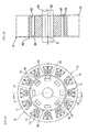
- a permanent-magnet embedded rotating electrical machine A (hereinafter referred to simply as a "rotating electrical machine A") is formed of an annular stator 10 constituting a part of a casing, not shown, and a columnar rotor 20 arranged coaxially with this stator 10.
- the stator 10 includes a stator core 11 and a plurality of coils 12.
- slots 13 are formed at equiangular intervals on the same circumference having a shaft center O at the center.
- the plurality of coils 12 are accommodated in the slots 13 formed in the stator core 11.
- the rotor 20 includes a rotor core 21, a rotating shaft 23 integrally rotating with the rotor core 21, and a plurality of permanent magnets 30.
- slots 22 are formed at equiangular intervals on the same circumference having the shaft center O at the center.
- the plurality of permanent magnets 30 are accommodated in the slots 22 formed in the rotor core 21.
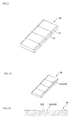
- the permanent magnet 30 accommodated in the slot 22 is, as illustrated in Fig. 2 , formed as a collection of magnet pieces 31 aligned in a row by bonding the plurality of magnet pieces 31 formed by fracturing and splitting the permanent magnet 30 with each other on fractured surfaces by a resin.
- the resin used is provided with heat resistance performances of approximately 200°C, for example, and electrically insulates the adjacent magnet pieces 31 from each other.
- a method of forming the notch groove includes a method of providing the notch groove by a projection for forming the groove provided in a molding die of the permanent magnet 30 in a molding process of the permanent magnet 30, a method by using mechanical machining such as a dicer, a method by using laser beam irradiation and the like.
- the depth and the sharpness of the distal end of the notch groove provided in the permanent magnet 30 have limitations.
- the flatness of the fractured surface when the permanent magnet is fractured into the magnet pieces 31 becomes low.
- the notch groove can be made deep and sharp.
- a distal end of the grinding stone is thin and deep, grinding stone rigidity is lowered, causing abrasion to occur early, and increasing a running cost.
- the depth and the sharpness of the distal end of the notch groove have limitations.
- the flatness of the fractured surface when the permanent magnet is fractured into the magnet pieces 31 becomes low.
- the distal end of the notch groove can be made sharp, and if the depth of the notch groove is to be suppressed, equipment to be used is inexpensive, and the running cost can be kept low.
- the depth of the notch groove it is only necessary to increase a laser beam output, but power consumption increases in proportion to the laser beam output and the equipment in use becomes expensive.
- a material in a region molten as the notch groove is pushed out to and accumulated on the both sides of the notch groove by a volume of the groove to be formed in the magnet surface. Eventually, the accumulated material causes burrs on the magnet surface on the both sides of the notch groove.
- a manufacturing method of the permanent magnet 30 in which the notch groove is formed by the method using the laser beam irradiation, and the burrs generated on the both sides of the notch groove are prevented from protruding from the magnet surface.
- Figs. 3 to 6 illustrate a manufacturing process of the permanent magnet 30 in this embodiment.
- the permanent magnet 30 Fig. 3
- a notch groove 33 Fig. 4
- the permanent magnet is fractured by an external force along the notch groove 33 ( Fig. 5 )
- fractured surfaces are bonded ( Fig. 6 ) to each other by a resin, and the permanent magnet 30 to be embedded in the rotor core 21 of the rotating electrical machine is formed.
- the permanent magnet 30 before the notch groove 33 is machined has, as illustrated in Fig. 3 , a trapezoidal groove 32A, for example, formed as the recess groove 32 in advance at a portion where the notch groove 33 is to be formed.
- This recess groove 32 is formed in a plurality of portions juxtaposed at equal intervals in a longitudinal direction, for example, to be fractured and split into a plurality of the magnet pieces 31 on one of surfaces of the permanent magnet 30 in a width direction of the permanent magnet 30.
- the recess groove 32 can be formed at the same time as sintering and molding of the permanent magnet 30 by using a molding die by providing a projection for forming a trapezoidal groove on a cavity surface of the molding die. In this case, since the projection for forming a trapezoidal groove provided on the cavity surface of the molding die does not have a sharp part, a trapezoidal groove 32A can be formed stably and inexpensively in the sintered and molded permanent magnet 30.
- the trapezoidal groove 32A may be ground and molded by a dicer in sintered and molded permanent magnet 30.
- a dicer since a sectional shape of the grinding stone is trapezoidal and does not have a sharp shape, abrasion of the grinding stone can be suppressed, and a running cost can be kept low.
- the depth of the trapezoidal groove 32A is determined by a depth dimension required for forming the notch groove 33 by using laser beam machining in a groove bottom 32B and an amount of pushed-out molten material, that is, a height dimension of a burr 34.
- a width of the notch groove 33 formed by using the laser beam machining is "A ⁇ m” and the depth of the notch groove 33 is "2 ⁇ A ⁇ m”
- the height of the burr 34 pushed out by the laser beam and accumulated becomes approximately "A ⁇ m".
- the depth of the trapezoidal groove 32A to be formed can be set to "A + 20 ⁇ m".
- a positional variation amount of the notch groove 33 by using the laser beam machining is " ⁇ B ⁇ m”
- a positional variation amount "2B ⁇ m” is further added, and the width dimension of the trapezoidal groove 32A to be formed can be set to "(3A + 2B) ⁇ m”.
- the positional variation amount of the notch grove 33 by using the laser beam machining is calculated from positioning accuracy of the permanent magnet 30 and beam positioning accuracy of a laser beam device.
- the trapezoidal groove 32A is described as the recess groove 32, but the recess groove 32 may be such that a side wall forms an arc shape and smoothly connects the groove bottom 32B and the surface of the permanent magnet 30.
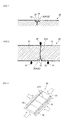
- a laser beam is applied to the groove bottom 32B of the trapezoidal groove 32A so as to form the notch groove 33 as illustrated in Fig. 4 .
- the material molten in the notch groove 33 is blown out by the laser beam from the notch groove 33 and accumulated as the burr 34 on the groove bottom 32B of the trapezoidal groove 32A located on the both sides of the notch groove 33.
- This burr 34 has, as described above, its distal end prevented from protruding from the surface of the permanent magnet 30 and is reliably accommodated in the trapezoidal groove 32A.
- the permanent magnet 30 is positioned so that a surface in which the recess groove 32 and the notch groove 33 are formed in the permanent magnet 30 comes to a lower surface and the recess groove 32 and the notch groove 33 are located at the center of a pair of supporting jigs 41 and placed on the supporting jigs 41. Then, a blade 42 aligned with the center of the notch groove 33 is brought into contact with a back surface of the permanent magnet 30 where the recess groove 32 and the notch groove 33 are located, and moreover, the blade 42 is pressed in an arrow direction and the permanent magnet 30 is bent at three points, so that the permanent magnet 30 is fractured and split into the magnet pieces 31.
- the pair of supporting jigs 41 are arranged symmetrically to the center of the blade 42, the blade 42 is arranged at a center position of the pair of supporting jigs 41, and the blade 42 is elevated up and down along the center position of the pair of the supporting jigs 41.
- the permanent magnet 30 is placed on the supporting jigs 41 with the center of the notch groove 33 aligned to the center of the blade 42. That is, the center of the notch groove 33 is positioned with respect to the center of the blade 42 and does not necessarily have to be matched with the center of the trapezoidal groove 32A. It is not the case if the center of the notch groove 33 accidentally matches the center of the trapezoidal groove 32A.
- Flatness which is an index of surface roughness of the fractured surface 31A of the magnet piece 31 can be, as illustrated in Fig. 10 , defined by an interval between a plane including the most dented spot in the fractured surface 31A and orthogonal to the longitudinal direction of the permanent magnet 30 and a plane in parallel with this plane and including the most protruding spot. From this interval, it can be determined that the smaller the interval, the higher the flatness, while the larger this interval, the lower the flatness.
- the flatness of the fractured surface 31A depends on the depth from a support surface by the supporting jigs 41 to a position at the distal end of the notch groove 33 which is a start point of crack occurrence in the bending at three points by the blade 42 and the pair of supporting jigs 41 and sharpness of a distal end R of the notch groove 33, that is, smallness of the R. That is, the deeper the depth from the support surface by the supporting jigs 41 to the position at the distal end of the notch groove 33, the better the flatness of the fractured surface 31A, while the shallower the depth, the worse the flatness of the fractured surface 31A.
- the sharper the distal end R of the notch groove 33 that is, the smaller the R, the better the flatness of the fractured surface 31A, while the duller the distal end R, that is, the larger the R, the worse the flatness of the fractured surface 31A.
- the notch groove 33 is formed in the groove bottom 32B of the trapezoidal groove 32A, the depth from the support surface by the supporting jigs 41 to the position of the distal end of the notch groove 33 can be made deeper, and the flatness of the fractured surface 31A can be improved. Moreover, the distal end R of the notch groove 33 can be formed sharp since the notch groove 33 is formed by using the laser beam irradiation, and the flatness of the fractured surface 31A can be improved in this point, too.
- a machining amount by the laser beam irradiation required to have the depth of the notch groove 33 with which the flatness of the fractured surface 31A is kept in a predetermined range is reduced by a portion of the depth of the trapezoidal groove 32A than the case where the notch groove 33 is formed without providing the trapezoidal groove 32A.
- a laser beam output for forming the notch groove 33 can be decreased, working time for the notch groove 33 can be reduced, and facilities such as laser beam equipment and the like can be simplified.
- an amount of the burrs 34 formed on the both sides of the notch groove 33 by the laser beam irradiation becomes relatively small, and the height of the burr 34 can be also lowered.
- each magnet piece 31 does not surface but can be aligned.
- a resin which becomes an adhesive is supplied between the magnet pieces 31.
- the supplied resin is filled between the opposing fractured surfaces 31A of the magnet pieces 31.
- the resin infiltrates over the whole region of the opposing fractured surfaces 31A and an excess resin is pushed out, so that the fractured surfaces 31A of the magnet pieces 31 are bonded to each other by the adhesive.
- the fractured surfaces 31A can be fitted with each other with accuracy by matching their respective projections and recesses accurately.
- the integrated permanent magnet 30 illustrated in Fig. 2 can be obtained.
- This permanent magnet 30 has, as illustrated in Fig. 9 , the fractured surfaces 31A bonded to each other by the resin, and the adjacent magnet pieces 31 electrically insulated. Therefore, in use by being assembled into the slot 22 of the rotor core 21, an eddy current generated by fluctuation in the acting magnetic field is retained in the individual magnet pieces 31 and reduced and heat generation caused by the eddy current is suppressed, thereby preventing irreversible thermal demagnetization.
- the burr 34 generated during formation of the notch groove 33 by using the laser beam irradiation is accommodated in the recess groove 32, and the distal end thereof does not protrude from the surface of the permanent magnet 30, inconvenience of the burr 34 getting caught by the edge of the slot 22 of the rotor core 21 and the permanent magnet 30 not being able to assemble to the rotor core 21 is prevented. Therefore, when the permanent magnet 30 is inserted into the slot 22, such inconvenience as the burr 34 separating from the permanent magnet 30 and drops into the rotating electrical machine case, causing biting into a rotating part and burning can be prevented.
Landscapes
- Engineering & Computer Science (AREA)
- Power Engineering (AREA)
- Manufacturing & Machinery (AREA)
- Physics & Mathematics (AREA)
- Electromagnetism (AREA)
- Permanent Field Magnets Of Synchronous Machinery (AREA)
- Manufacture Of Motors, Generators (AREA)
Abstract
Description
- The present invention relates to a permanent magnet disposed in a rotating electrical machine such as an electric motor and an electric generator, and a manufacturing method of the same.
- Conventionally, by splitting a permanent magnet embedded in a rotor core of a rotating electrical machine by cleaving so as to reduce its surface area, an eddy current generated by fluctuation in an acting magnetic field has been reduced and heat generation of the permanent magnet caused by the eddy current has been suppressed, thereby preventing irreversible thermal demagnetization.
- In
JP2009-142081A - When the notch which becomes the target of the cleaving is provided in the permanent magnet as in
JP2009-142081A - The present invention has an object, therefore, to provide a permanent magnet disposed in a rotor core of a rotating electrical machine and a manufacturing method of the same suitable for aligning and binding magnet pieces without displacement.
- In order to achieve the above-described object, the present invention is characterized by including a process of forming a recess groove having a depth shallower than that of a notch groove for fracturing and a width larger than a width of the notch groove at a portion of fracturing and splitting of the permanent magnet, a process of forming a notch groove for fracturing the permanent magnet in a groove bottom of the recess groove formed in the recess-groove forming process, and a process of fracturing and splitting the permanent magnet along the notch groove so as to obtain magnet pieces.
- The details and other characteristics and merits of this invention will be explained in the description below and illustrated in the attached drawings.
-
-
Fig. 1A is a front view illustrating an outline configuration of a rotating electrical machine to which a permanent magnet according to an embodiment of the present invention is applied. -
Fig. 1B is a sectional view along I-I line inFig. 1A . -
Fig. 2 is a perspective view of the permanent magnet. -
Fig. 3A is a perspective view illustrating a manufacturing process of the permanent magnet. -
Fig. 3B is a sectional view of an essential part ofFig. 3A . -
Fig. 4 is a sectional view of the essential part illustrating a manufacturing process subsequent toFig. 3 of the permanent magnet. -
Fig. 5 is a sectional view of the essential part illustrating a manufacturing process subsequent toFig. 4 of the permanent magnet. -
Fig. 6 is a perspective view illustrating a manufacturing process subsequent toFig. 5 of the permanent magnet. -
Fig. 7 is a detailed sectional view of the essential part of the permanent magnet before fracturing. -
Fig. 8 is a sectional view illustrating a state when the permanent magnet is fractured. -
Fig. 9 is a sectional view of the essential part of the permanent magnet illustrating a state where magnet pieces are bonded. -
Fig. 10 is an explanatory diagram for explaining flatness of a fractured surface. - A permanent magnet disposed in a rotor core of a rotating electrical machine and a manufacturing method of the same of the present invention will be described below on the basis of an embodiment illustrated in
Figs. 1 to 10 . - In
Fig. 1 , a permanent-magnet embedded rotating electrical machine A (hereinafter referred to simply as a "rotating electrical machine A") is formed of anannular stator 10 constituting a part of a casing, not shown, and acolumnar rotor 20 arranged coaxially with thisstator 10. - The
stator 10 includes a stator core 11 and a plurality ofcoils 12. In the stator core 11,slots 13 are formed at equiangular intervals on the same circumference having a shaft center O at the center. The plurality ofcoils 12 are accommodated in theslots 13 formed in the stator core 11. - The
rotor 20 includes arotor core 21, a rotatingshaft 23 integrally rotating with therotor core 21, and a plurality ofpermanent magnets 30. In therotor core 21,slots 22 are formed at equiangular intervals on the same circumference having the shaft center O at the center. The plurality ofpermanent magnets 30 are accommodated in theslots 22 formed in therotor core 21. - The
permanent magnet 30 accommodated in theslot 22 is, as illustrated inFig. 2 , formed as a collection ofmagnet pieces 31 aligned in a row by bonding the plurality ofmagnet pieces 31 formed by fracturing and splitting thepermanent magnet 30 with each other on fractured surfaces by a resin. The resin used is provided with heat resistance performances of approximately 200°C, for example, and electrically insulates theadjacent magnet pieces 31 from each other. As a result, since an eddy current generated by fluctuation in an acting magnetic field remains in each of themagnet pieces 31 and is reduced, heat generation of thepermanent magnet 30 caused by the eddy current is suppressed, and irreversible thermal demagnetization can be prevented. - In order to fracture and split the
permanent magnet 30 into a plurality of themagnet pieces 31, it is effective to form a notch groove in advance at a portion where thepermanent magnet 30 is to be fractured. The deeper the depth from the surface or the sharper the distal end of the notch groove, the better the flatness of a fractured surface of the notch groove. - A method of forming the notch groove includes a method of providing the notch groove by a projection for forming the groove provided in a molding die of the
permanent magnet 30 in a molding process of thepermanent magnet 30, a method by using mechanical machining such as a dicer, a method by using laser beam irradiation and the like. - With the method of providing the notch groove by a protrusion for forming a groove provided in the molding die of the
permanent magnet 30 in the molding process of thepermanent magnet 30, the depth and the sharpness of the distal end of the notch groove provided in thepermanent magnet 30 have limitations. Thus, the flatness of the fractured surface when the permanent magnet is fractured into themagnet pieces 31 becomes low. - With the method by using mechanical machining such as a dicer or the like, if the distal end shape of a grinding stone is made sharp, the notch groove can be made deep and sharp. However, if a distal end of the grinding stone is thin and deep, grinding stone rigidity is lowered, causing abrasion to occur early, and increasing a running cost. Thus, in this method, too, the depth and the sharpness of the distal end of the notch groove have limitations. Thus, the flatness of the fractured surface when the permanent magnet is fractured into the
magnet pieces 31 becomes low. - With the method using laser beam irradiation, the distal end of the notch groove can be made sharp, and if the depth of the notch groove is to be suppressed, equipment to be used is inexpensive, and the running cost can be kept low. In order to increase the depth of the notch groove, it is only necessary to increase a laser beam output, but power consumption increases in proportion to the laser beam output and the equipment in use becomes expensive. Moreover, with the method using the laser beam irradiation, a material in a region molten as the notch groove is pushed out to and accumulated on the both sides of the notch groove by a volume of the groove to be formed in the magnet surface. Eventually, the accumulated material causes burrs on the magnet surface on the both sides of the notch groove.
- Thus, in this embodiment, a manufacturing method of the
permanent magnet 30 is provided in which the notch groove is formed by the method using the laser beam irradiation, and the burrs generated on the both sides of the notch groove are prevented from protruding from the magnet surface. -
Figs. 3 to 6 illustrate a manufacturing process of thepermanent magnet 30 in this embodiment. First, the permanent magnet 30 (Fig. 3 ) having arecess groove 32 is formed, then a notch groove 33 (Fig. 4 ) is formed by applying a laser beam to therecess groove 32. Subsequently, the permanent magnet is fractured by an external force along the notch groove 33 (Fig. 5 ), fractured surfaces are bonded (Fig. 6 ) to each other by a resin, and thepermanent magnet 30 to be embedded in therotor core 21 of the rotating electrical machine is formed. Each process will be described below in detail. - The
permanent magnet 30 before thenotch groove 33 is machined has, as illustrated inFig. 3 , atrapezoidal groove 32A, for example, formed as therecess groove 32 in advance at a portion where thenotch groove 33 is to be formed. Thisrecess groove 32 is formed in a plurality of portions juxtaposed at equal intervals in a longitudinal direction, for example, to be fractured and split into a plurality of themagnet pieces 31 on one of surfaces of thepermanent magnet 30 in a width direction of thepermanent magnet 30. Therecess groove 32 can be formed at the same time as sintering and molding of thepermanent magnet 30 by using a molding die by providing a projection for forming a trapezoidal groove on a cavity surface of the molding die. In this case, since the projection for forming a trapezoidal groove provided on the cavity surface of the molding die does not have a sharp part, atrapezoidal groove 32A can be formed stably and inexpensively in the sintered and moldedpermanent magnet 30. - Moreover, as another molding method of the
trapezoidal groove 32A, the trapezoidal groove may be ground and molded by a dicer in sintered and moldedpermanent magnet 30. In the case of molding by using a dicer, since a sectional shape of the grinding stone is trapezoidal and does not have a sharp shape, abrasion of the grinding stone can be suppressed, and a running cost can be kept low. - The depth of the
trapezoidal groove 32A is determined by a depth dimension required for forming thenotch groove 33 by using laser beam machining in agroove bottom 32B and an amount of pushed-out molten material, that is, a height dimension of aburr 34. For example, as illustrated inFig. 7 , assuming that a width of thenotch groove 33 formed by using the laser beam machining is "A µm" and the depth of thenotch groove 33 is "2 × A µm", the height of theburr 34 pushed out by the laser beam and accumulated becomes approximately "A µm". Thus, by setting the depth of thetrapezoidal groove 32A to be formed to a dimension larger than the height "A µm" of the accumulatedburr 34, the distal end of theburr 34 can be prevented from protruding from the surface of thepermanent magnet 30. Here, considering variation in the height of theburr 34, if a standard value of the height of theburr 34 is "A µm" and the variation is "± 20 µm", for example, the depth of thetrapezoidal groove 32A to be formed can be set to "A + 20 µm". - Moreover, the width of the
trapezoidal groove 32A is determined on the basis of a dimension obtained by adding a width dimension of theburr 34 formed on the both sides of thenotch groove 33 by using the laser beam machining to the width dimension of thenotch groove 33 formed by using the laser beam machining. For example, assuming that the width dimension of thenotch groove 33 is "A µm" and the width dimension of theburr 34 is "2A µm", a dimension exceeding the dimension "A µm + 2A µm = 3A µm" obtained by adding up all these width dimensions is a width dimension of thetrapezoidal groove 32A to be formed. Here, if a positional variation amount of thenotch groove 33 by using the laser beam machining is "± B µm", a positional variation amount "2B µm" is further added, and the width dimension of thetrapezoidal groove 32A to be formed can be set to "(3A + 2B) µm". The positional variation amount of thenotch grove 33 by using the laser beam machining is calculated from positioning accuracy of thepermanent magnet 30 and beam positioning accuracy of a laser beam device. By setting as above, thenotch groove 33 and theburr 34 can be reliably accommodated in thetrapezoidal groove 32A. - In the above, the
trapezoidal groove 32A is described as therecess groove 32, but therecess groove 32 may be such that a side wall forms an arc shape and smoothly connects thegroove bottom 32B and the surface of thepermanent magnet 30. - Subsequently, a laser beam is applied to the
groove bottom 32B of thetrapezoidal groove 32A so as to form thenotch groove 33 as illustrated inFig. 4 . The material molten in thenotch groove 33 is blown out by the laser beam from thenotch groove 33 and accumulated as theburr 34 on thegroove bottom 32B of thetrapezoidal groove 32A located on the both sides of thenotch groove 33. Thisburr 34 has, as described above, its distal end prevented from protruding from the surface of thepermanent magnet 30 and is reliably accommodated in thetrapezoidal groove 32A. - Subsequently, as illustrated in
Figs. 5 and8 , thepermanent magnet 30 is positioned so that a surface in which therecess groove 32 and thenotch groove 33 are formed in thepermanent magnet 30 comes to a lower surface and therecess groove 32 and thenotch groove 33 are located at the center of a pair of supportingjigs 41 and placed on the supportingjigs 41. Then, ablade 42 aligned with the center of thenotch groove 33 is brought into contact with a back surface of thepermanent magnet 30 where therecess groove 32 and thenotch groove 33 are located, and moreover, theblade 42 is pressed in an arrow direction and thepermanent magnet 30 is bent at three points, so that thepermanent magnet 30 is fractured and split into themagnet pieces 31. - In this case, the pair of supporting
jigs 41 are arranged symmetrically to the center of theblade 42, theblade 42 is arranged at a center position of the pair of supportingjigs 41, and theblade 42 is elevated up and down along the center position of the pair of the supportingjigs 41. Then, thepermanent magnet 30 is placed on the supportingjigs 41 with the center of thenotch groove 33 aligned to the center of theblade 42. That is, the center of thenotch groove 33 is positioned with respect to the center of theblade 42 and does not necessarily have to be matched with the center of thetrapezoidal groove 32A. It is not the case if the center of thenotch groove 33 accidentally matches the center of thetrapezoidal groove 32A. - Flatness which is an index of surface roughness of the fractured
surface 31A of themagnet piece 31 can be, as illustrated inFig. 10 , defined by an interval between a plane including the most dented spot in the fracturedsurface 31A and orthogonal to the longitudinal direction of thepermanent magnet 30 and a plane in parallel with this plane and including the most protruding spot. From this interval, it can be determined that the smaller the interval, the higher the flatness, while the larger this interval, the lower the flatness. - The flatness of the fractured
surface 31A depends on the depth from a support surface by the supportingjigs 41 to a position at the distal end of thenotch groove 33 which is a start point of crack occurrence in the bending at three points by theblade 42 and the pair of supportingjigs 41 and sharpness of a distal end R of thenotch groove 33, that is, smallness of the R. That is, the deeper the depth from the support surface by the supportingjigs 41 to the position at the distal end of thenotch groove 33, the better the flatness of the fracturedsurface 31A, while the shallower the depth, the worse the flatness of the fracturedsurface 31A. Moreover, the sharper the distal end R of thenotch groove 33, that is, the smaller the R, the better the flatness of the fracturedsurface 31A, while the duller the distal end R, that is, the larger the R, the worse the flatness of the fracturedsurface 31A. - Moreover, the slower an increase speed of a pushing-in load of the
blade 42, the better the flatness of the fracturedsurface 31A, while the faster the increase speed, the worse the flatness. - In this embodiment, since the
notch groove 33 is formed in thegroove bottom 32B of thetrapezoidal groove 32A, the depth from the support surface by the supportingjigs 41 to the position of the distal end of thenotch groove 33 can be made deeper, and the flatness of the fracturedsurface 31A can be improved. Moreover, the distal end R of thenotch groove 33 can be formed sharp since thenotch groove 33 is formed by using the laser beam irradiation, and the flatness of the fracturedsurface 31A can be improved in this point, too. - Moreover, since the
notch groove 33 is formed in thegroove bottom 32B of thetrapezoidal groove 32A, a machining amount by the laser beam irradiation required to have the depth of thenotch groove 33 with which the flatness of the fracturedsurface 31A is kept in a predetermined range is reduced by a portion of the depth of thetrapezoidal groove 32A than the case where thenotch groove 33 is formed without providing thetrapezoidal groove 32A. Thus, a laser beam output for forming thenotch groove 33 can be decreased, working time for thenotch groove 33 can be reduced, and facilities such as laser beam equipment and the like can be simplified. At the same time, an amount of theburrs 34 formed on the both sides of thenotch groove 33 by the laser beam irradiation becomes relatively small, and the height of theburr 34 can be also lowered. - Subsequently, a plurality of fractured and split
magnet pieces 31 are aligned at intervals. In this case, since theburr 34 generated during formation of thenotch groove 33 by using laser beam irradiation is accommodated in therecess groove 32 and the distal end thereof does not protrude from the surface of the magnet, whichever surface of themagnet piece 31 is oriented downward in alignment, eachmagnet piece 31 does not surface but can be aligned. - Subsequently, a resin which becomes an adhesive is supplied between the
magnet pieces 31. The supplied resin is filled between the opposing fracturedsurfaces 31A of themagnet pieces 31. Then, as illustrated inFig. 6 , by pressurizing from the longitudinal direction of thepermanent magnet 30 in a state where an aligningjig 50 is pressed from the width direction of thepermanent magnet 30, the resin infiltrates over the whole region of the opposing fracturedsurfaces 31A and an excess resin is pushed out, so that the fractured surfaces 31A of themagnet pieces 31 are bonded to each other by the adhesive. Moreover, as described above, since the flatness of the fracturedsurfaces 31A can be made higher, the fracturedsurfaces 31A can be fitted with each other with accuracy by matching their respective projections and recesses accurately. - Accordingly, the integrated
permanent magnet 30 illustrated inFig. 2 can be obtained. Thispermanent magnet 30 has, as illustrated inFig. 9 , the fracturedsurfaces 31A bonded to each other by the resin, and theadjacent magnet pieces 31 electrically insulated. Therefore, in use by being assembled into theslot 22 of therotor core 21, an eddy current generated by fluctuation in the acting magnetic field is retained in theindividual magnet pieces 31 and reduced and heat generation caused by the eddy current is suppressed, thereby preventing irreversible thermal demagnetization. Moreover, since theburr 34 generated during formation of thenotch groove 33 by using the laser beam irradiation is accommodated in therecess groove 32, and the distal end thereof does not protrude from the surface of thepermanent magnet 30, inconvenience of theburr 34 getting caught by the edge of theslot 22 of therotor core 21 and thepermanent magnet 30 not being able to assemble to therotor core 21 is prevented. Therefore, when thepermanent magnet 30 is inserted into theslot 22, such inconvenience as theburr 34 separating from thepermanent magnet 30 and drops into the rotating electrical machine case, causing biting into a rotating part and burning can be prevented. - The embodiment of the present invention has been described but the above-described embodiment illustrates only a part of application examples of the present invention and is not intended to limit a technical scope of the present invention to a specific configuration of the above-described embodiment.
- This application claims for priority on the basis of Japanese Patent Application No.
2010-115125
Claims (4)
- A manufacturing method of a permanent magnet (30) disposed in a rotating electrical machine (A), in which a plurality of magnet pieces (31) formed by fracturing and splitting the permanent magnet (30) along a notch groove (33) are aligned and bonded to each other, comprising:a step of forming a recess groove (32) having a depth shallower than and a width larger than the notch groove (33) at a portion of fracturing and splitting in the permanent magnet (30);a step of forming the notch groove (33) for fracturing the permanent magnet (30) in a groove bottom (32B) of the recess groove (32) formed in the recess-groove forming step; anda step of fracturing and splitting the permanent magnet (30) along the notch groove (33) so as to obtain magnet pieces (31).
- The manufacturing method of the permanent magnet (30) disposed in the rotating electrical machine (A) according to claim 1, wherein
the recess groove (32) is provided with a groove width 3 times or more with respect to the groove width of the notch groove (33) formed in the groove bottom (32B) of the recess groove(32) and is provided with a depth 0.5 times or more with respect to a groove depth of the notch groove (33). - The manufacturing method of the permanent magnet (30) disposed in the rotating electrical machine (A) according to claim 1 or 2, wherein
a sectional shape of the recess groove (32) is trapezoidal whose groove width becomes smaller toward the groove bottom (32B). - A permanent magnet (30) disposed in a rotating electrical machine (A), in which a plurality of magnet pieces (31) formed by fracturing and splitting the permanent magnet (30) along a notch groove (33) are aligned and bonded to each other, comprising:a recess groove (32A) having a depth shallower than and a width larger than the notch groove (33) located at a portion of fracturing and splitting in the permanent magnet (30) and a notch groove (33) for fracturing of the permanent magnet (30) formed in a groove bottom of the recess groove (32A), whereinthe permanent magnet (30) disposed in the rotating electrical machine (A) is fractured and split along the notch groove (33), and the fractured surfaces thereof are bonded to each other.
Applications Claiming Priority (2)
| Application Number | Priority Date | Filing Date | Title |
|---|---|---|---|
| JP2010115125A JP5614096B2 (en) | 2010-05-19 | 2010-05-19 | Permanent magnet embedded in rotor core of rotating electrical machine and method for manufacturing the same |
| PCT/JP2011/059968 WO2011145433A1 (en) | 2010-05-19 | 2011-04-22 | Permanent magnet provided to dynamo-electric machine, and method for manufacturing same |
Publications (3)
| Publication Number | Publication Date |
|---|---|
| EP2573916A1 true EP2573916A1 (en) | 2013-03-27 |
| EP2573916A4 EP2573916A4 (en) | 2017-01-04 |
| EP2573916B1 EP2573916B1 (en) | 2017-10-25 |
Family
ID=44991547
Family Applications (1)
| Application Number | Title | Priority Date | Filing Date |
|---|---|---|---|
| EP11783370.7A Active EP2573916B1 (en) | 2010-05-19 | 2011-04-22 | Permanent magnet provided to dynamo-electric machine, and method for manufacturing same |
Country Status (8)
| Country | Link |
|---|---|
| US (1) | US8819921B2 (en) |
| EP (1) | EP2573916B1 (en) |
| JP (1) | JP5614096B2 (en) |
| KR (1) | KR101332513B1 (en) |
| CN (1) | CN102906979B (en) |
| AU (1) | AU2011256564B2 (en) |
| CA (1) | CA2800619C (en) |
| WO (1) | WO2011145433A1 (en) |
Cited By (2)
| Publication number | Priority date | Publication date | Assignee | Title |
|---|---|---|---|---|
| EP2899859A4 (en) * | 2012-09-21 | 2015-09-23 | Nissan Motor | DEVICE FOR MANUFACTURING A CRAWLING MAGNET |
| EP3041114A4 (en) * | 2013-08-29 | 2016-08-31 | Nissan Motor | CUTTING METHOD AND CUTTING DEVICE FOR MANUFACTURING A MAGNET PIECE COMPRISING A POLAR PIECE MAGNET BODY TO BE INSTALLED IN A ROTATING ELECTRIC MACHINE |
Families Citing this family (27)
| Publication number | Priority date | Publication date | Assignee | Title |
|---|---|---|---|---|
| EP2712059A1 (en) * | 2011-05-19 | 2014-03-26 | Toyota Jidosha Kabushiki Kaisha | Method for manufacturing rotor and cutting apparatus |
| EP2738922B1 (en) * | 2011-07-27 | 2020-03-25 | Nissan Motor Co., Ltd | Device for producing field-pole magnet and method for producing same |
| JP6393019B2 (en) * | 2011-09-26 | 2018-09-19 | 日産自動車株式会社 | Field pole magnet body manufacturing apparatus and method |
| JP5910036B2 (en) * | 2011-11-30 | 2016-04-27 | 株式会社ジェイテクト | Manufacturing method of rotor for rotating machine |
| JP5867052B2 (en) * | 2011-12-14 | 2016-02-24 | 日産自動車株式会社 | Field pole magnet body manufacturing apparatus and method |
| JP5929153B2 (en) | 2011-12-14 | 2016-06-01 | 日産自動車株式会社 | Field pole magnet body manufacturing apparatus and method |
| US9659707B2 (en) | 2011-12-15 | 2017-05-23 | Nissan Motor Co., Ltd. | Manufacturing device for field-pole magnet and manufacturing method for same |
| FR2985085B1 (en) * | 2011-12-23 | 2014-02-21 | Alstom Technology Ltd | ELECTROMAGNETIC ACTUATOR WITH PERMANENT MAGNETS AND MECHANICAL DISCONNECT SWITCH-ACTUATOR ACTUATED BY SUCH ACTUATOR |
| JP6035024B2 (en) * | 2012-01-10 | 2016-11-30 | 大同特殊鋼株式会社 | Method for producing non-cylindrical permanent magnet |
| WO2013115224A1 (en) * | 2012-02-01 | 2013-08-08 | 日産自動車株式会社 | Method for manufacturing magnet pieces for forming field-pole magnets |
| JP5935378B2 (en) * | 2012-02-21 | 2016-06-15 | 日産自動車株式会社 | Magnet piece manufacturing apparatus constituting field pole magnet body |
| JP5994280B2 (en) * | 2012-02-21 | 2016-09-21 | 日産自動車株式会社 | Manufacturing method and manufacturing apparatus of magnet piece constituting magnet body for field pole |
| JP5929310B2 (en) * | 2012-02-28 | 2016-06-01 | 日産自動車株式会社 | Manufacturing method of magnet piece constituting magnetic body for field pole |
| JP5919888B2 (en) * | 2012-03-01 | 2016-05-18 | 日産自動車株式会社 | A cleaving method and a cleaving apparatus for cleaving a permanent magnet body into a magnet piece constituting a field pole magnet body disposed in a rotating electrical machine |
| JP5849774B2 (en) * | 2012-03-01 | 2016-02-03 | 日産自動車株式会社 | A cleaving method and a cleaving apparatus for cleaving a permanent magnet body into a magnet piece constituting a field pole magnet body disposed in a rotating electrical machine |
| EP2869440B1 (en) * | 2012-07-02 | 2017-02-01 | Nissan Motor Co., Ltd. | Apparatus and method for manufacturing magnet segments constituting field pole magnetic body |
| JP5880709B2 (en) * | 2012-07-13 | 2016-03-09 | 日産自動車株式会社 | Field pole magnet manufacturing apparatus |
| JP5994447B2 (en) * | 2012-07-13 | 2016-09-21 | 日産自動車株式会社 | Magnet piece manufacturing apparatus constituting field pole magnet body and manufacturing method thereof |
| US20150229194A1 (en) * | 2012-08-27 | 2015-08-13 | Albus Technologies Ltd. | Rotor with magnet pattern |
| JP6015458B2 (en) * | 2013-01-17 | 2016-10-26 | 日産自動車株式会社 | Magnet body for field pole, manufacturing method and manufacturing apparatus thereof |
| JP6111679B2 (en) * | 2013-01-17 | 2017-04-12 | 日産自動車株式会社 | Magnet body for field pole and manufacturing method thereof |
| US10668641B2 (en) * | 2013-06-13 | 2020-06-02 | Nissan Motor Co., Ltd. | Magnet cutting device |
| JP6322911B2 (en) * | 2013-07-05 | 2018-05-16 | 大同特殊鋼株式会社 | Method for producing non-cylindrical permanent magnet |
| EP3057207B1 (en) * | 2013-10-09 | 2018-10-10 | Nissan Motor Co., Ltd | Method and device for manufacturing magnet pieces configuring a field pole magnet to be arranged in a rotary machine |
| JP6481642B2 (en) * | 2016-03-03 | 2019-03-13 | トヨタ自動車株式会社 | Manufacturing method of rotor |
| US11004586B2 (en) | 2017-09-15 | 2021-05-11 | Siemens Gamesa Renewable Energy A/S | Permanent magnet for a permanent magnet machine |
| EP3457532B1 (en) * | 2017-09-15 | 2023-02-01 | Siemens Gamesa Renewable Energy A/S | Permanent magnet for a permanent magnet machine |
Family Cites Families (23)
| Publication number | Priority date | Publication date | Assignee | Title |
|---|---|---|---|---|
| JPS5826199B2 (en) * | 1980-09-26 | 1983-06-01 | 日立化成工業株式会社 | Manufacturing method of printed wiring board with metal core |
| US5201117A (en) * | 1991-11-04 | 1993-04-13 | General Motors Corporation | Method and apparatus for sizing and cutting tubing |
| JPH067316A (en) * | 1992-06-29 | 1994-01-18 | Hitachi Medical Corp | Magnetic field generating device of magnetic resonance imaging system |
| US6335623B1 (en) * | 1992-12-18 | 2002-01-01 | Fonar Corporation | MRI apparatus |
| US5634263A (en) * | 1995-09-11 | 1997-06-03 | The United States Of America As Represented By The Secretary Of The Army | Methods of manufacture of permanent magnet structures with sheet material |
| US5523732A (en) * | 1995-10-16 | 1996-06-04 | The United States Of America As Represented By The Secretary Of The Army | Multi-mode adjustable magic ring |
| US7127802B1 (en) * | 1997-11-21 | 2006-10-31 | Fonar Corporation | Method of fabricating a composite plate |
| US20010031336A1 (en) * | 2000-01-14 | 2001-10-18 | Born David W. | Composite backerboard articles for construction |
| US6940379B2 (en) * | 2000-04-11 | 2005-09-06 | Stereotaxis, Inc. | Magnets with varying magnetization direction and method of making such magnets |
| JP3826022B2 (en) * | 2000-12-15 | 2006-09-27 | キヤノン株式会社 | Substrate having wiring, electron source, and image display device |
| JP4623848B2 (en) * | 2001-03-23 | 2011-02-02 | 日立金属株式会社 | Magnetic field generator |
| US7039280B2 (en) * | 2001-09-17 | 2006-05-02 | Tdk Corporation | Embedded type optical isolator and method for manufacturing the same |
| US6790308B2 (en) * | 2003-01-03 | 2004-09-14 | Borgwarner Inc. | Method and apparatus for making clutch plate with multi segment friction material |
| JP2005116844A (en) | 2003-10-09 | 2005-04-28 | Matsushita Electric Ind Co Ltd | Manufacturing method of semiconductor device |
| CN1670978B (en) * | 2004-02-26 | 2010-12-29 | 京瓷株式会社 | Electronic device manufacturing method |
| DE102004020063A1 (en) * | 2004-04-24 | 2005-11-17 | Man Nutzfahrzeuge Ag | Process for fracture separation of reassemblable components or their materials |
| JP2006086516A (en) * | 2004-08-20 | 2006-03-30 | Showa Denko Kk | Manufacturing method of semiconductor light emitting device |
| JP4246136B2 (en) | 2004-10-21 | 2009-04-02 | 三菱電機株式会社 | Manufacturing method of electric motor rotor, electric motor rotor, electric motor, air conditioner, refrigerator, ventilation fan, and electric motor rotor resin mold |
| JP4750427B2 (en) * | 2005-01-13 | 2011-08-17 | 株式会社ディスコ | Wafer laser processing method |
| JP4655672B2 (en) * | 2005-02-25 | 2011-03-23 | 国産電機株式会社 | Flywheel magnet rotor and manufacturing method thereof |
| JP4312778B2 (en) * | 2006-08-09 | 2009-08-12 | 三菱電機株式会社 | Magnet generator manufacturing method |
| JP4497198B2 (en) | 2007-12-06 | 2010-07-07 | トヨタ自動車株式会社 | Permanent magnet and method for manufacturing the same, and rotor and IPM motor |
| CN102171908B (en) | 2008-10-02 | 2014-05-28 | 日产自动车株式会社 | Field pole magnet, field pole magnet manufacturing method, and permanent magnet rotary machine |
-
2010
- 2010-05-19 JP JP2010115125A patent/JP5614096B2/en active Active
-
2011
- 2011-04-22 WO PCT/JP2011/059968 patent/WO2011145433A1/en not_active Ceased
- 2011-04-22 CA CA2800619A patent/CA2800619C/en active Active
- 2011-04-22 US US13/698,574 patent/US8819921B2/en active Active
- 2011-04-22 KR KR1020127031128A patent/KR101332513B1/en not_active Expired - Fee Related
- 2011-04-22 CN CN201180024724.4A patent/CN102906979B/en active Active
- 2011-04-22 EP EP11783370.7A patent/EP2573916B1/en active Active
- 2011-04-22 AU AU2011256564A patent/AU2011256564B2/en not_active Ceased
Cited By (4)
| Publication number | Priority date | Publication date | Assignee | Title |
|---|---|---|---|---|
| EP2899859A4 (en) * | 2012-09-21 | 2015-09-23 | Nissan Motor | DEVICE FOR MANUFACTURING A CRAWLING MAGNET |
| US9779871B2 (en) | 2012-09-21 | 2017-10-03 | Nissan Motor Co., Ltd. | Manufacturing device for cleft magnet |
| EP3041114A4 (en) * | 2013-08-29 | 2016-08-31 | Nissan Motor | CUTTING METHOD AND CUTTING DEVICE FOR MANUFACTURING A MAGNET PIECE COMPRISING A POLAR PIECE MAGNET BODY TO BE INSTALLED IN A ROTATING ELECTRIC MACHINE |
| US9754719B2 (en) | 2013-08-29 | 2017-09-05 | Nissan Motor Co., Ltd. | Cutting method and cutting device of manufacturing magnet piece forming magnet body for field pole to be arranged in rotating electric machine |
Also Published As
| Publication number | Publication date |
|---|---|
| AU2011256564A1 (en) | 2013-01-10 |
| EP2573916A4 (en) | 2017-01-04 |
| US8819921B2 (en) | 2014-09-02 |
| EP2573916B1 (en) | 2017-10-25 |
| JP2011244613A (en) | 2011-12-01 |
| CN102906979B (en) | 2015-06-03 |
| KR20130022409A (en) | 2013-03-06 |
| KR101332513B1 (en) | 2013-11-22 |
| CA2800619C (en) | 2017-04-11 |
| CA2800619A1 (en) | 2011-11-24 |
| WO2011145433A1 (en) | 2011-11-24 |
| JP5614096B2 (en) | 2014-10-29 |
| US20130057374A1 (en) | 2013-03-07 |
| AU2011256564B2 (en) | 2014-03-06 |
| CN102906979A (en) | 2013-01-30 |
Similar Documents
| Publication | Publication Date | Title |
|---|---|---|
| EP2573916B1 (en) | Permanent magnet provided to dynamo-electric machine, and method for manufacturing same | |
| US8497613B2 (en) | Permanent magnet, manufacturing method thereof, and rotor and IPM motor | |
| US7973442B2 (en) | Permanent magnet-type rotary electric machine and production method for rotor for permanent magnet-type rotary electric machine | |
| EP2811628A1 (en) | Method for manufacturing magnet pieces for forming field-pole magnets | |
| JP2010259231A (en) | Permanent magnet for field pole, method for manufacturing the same, and permanent magnet type rotating electrical machine provided with permanent magnet for field pole | |
| CN105580245B (en) | Cut-off method and chopping up apparatus that the field pole configured to being formed in electric rotating machine is manufactured with the magnetite pieces of magnetite body | |
| KR20130141700A (en) | Method for manufacturing rotor and cutting apparatus | |
| JP5360224B2 (en) | Method for manufacturing electric motor rotor | |
| JP5994280B2 (en) | Manufacturing method and manufacturing apparatus of magnet piece constituting magnet body for field pole | |
| CN104067489B (en) | Constitute the manufacture method of the magnet sheet of field pole magnet | |
| JP6015458B2 (en) | Magnet body for field pole, manufacturing method and manufacturing apparatus thereof | |
| JP5919888B2 (en) | A cleaving method and a cleaving apparatus for cleaving a permanent magnet body into a magnet piece constituting a field pole magnet body disposed in a rotating electrical machine | |
| WO2013115301A1 (en) | Device for manufacturing magnet pieces for forming field-pole magnets | |
| JP5761383B2 (en) | Method for manufacturing field pole magnet body |
Legal Events
| Date | Code | Title | Description |
|---|---|---|---|
| PUAI | Public reference made under article 153(3) epc to a published international application that has entered the european phase |
Free format text: ORIGINAL CODE: 0009012 |
|
| 17P | Request for examination filed |
Effective date: 20121219 |
|
| AK | Designated contracting states |
Kind code of ref document: A1 Designated state(s): AL AT BE BG CH CY CZ DE DK EE ES FI FR GB GR HR HU IE IS IT LI LT LU LV MC MK MT NL NO PL PT RO RS SE SI SK SM TR |
|
| DAX | Request for extension of the european patent (deleted) | ||
| RA4 | Supplementary search report drawn up and despatched (corrected) |
Effective date: 20161201 |
|
| RIC1 | Information provided on ipc code assigned before grant |
Ipc: H01F 41/02 20060101ALI20161125BHEP Ipc: H01F 7/02 20060101ALI20161125BHEP Ipc: H02K 1/27 20060101ALI20161125BHEP Ipc: H02K 15/03 20060101AFI20161125BHEP |
|
| GRAP | Despatch of communication of intention to grant a patent |
Free format text: ORIGINAL CODE: EPIDOSNIGR1 |
|
| INTG | Intention to grant announced |
Effective date: 20170616 |
|
| GRAS | Grant fee paid |
Free format text: ORIGINAL CODE: EPIDOSNIGR3 |
|
| GRAA | (expected) grant |
Free format text: ORIGINAL CODE: 0009210 |
|
| AK | Designated contracting states |
Kind code of ref document: B1 Designated state(s): AL AT BE BG CH CY CZ DE DK EE ES FI FR GB GR HR HU IE IS IT LI LT LU LV MC MK MT NL NO PL PT RO RS SE SI SK SM TR |
|
| REG | Reference to a national code |
Ref country code: GB Ref legal event code: FG4D |
|
| REG | Reference to a national code |
Ref country code: CH Ref legal event code: EP |
|
| REG | Reference to a national code |
Ref country code: AT Ref legal event code: REF Ref document number: 940769 Country of ref document: AT Kind code of ref document: T Effective date: 20171115 |
|
| REG | Reference to a national code |
Ref country code: IE Ref legal event code: FG4D |
|
| REG | Reference to a national code |
Ref country code: DE Ref legal event code: R096 Ref document number: 602011042731 Country of ref document: DE |
|
| REG | Reference to a national code |
Ref country code: NL Ref legal event code: MP Effective date: 20171025 |
|
| REG | Reference to a national code |
Ref country code: LT Ref legal event code: MG4D |
|
| REG | Reference to a national code |
Ref country code: AT Ref legal event code: MK05 Ref document number: 940769 Country of ref document: AT Kind code of ref document: T Effective date: 20171025 |
|
| PG25 | Lapsed in a contracting state [announced via postgrant information from national office to epo] |
Ref country code: NL Free format text: LAPSE BECAUSE OF FAILURE TO SUBMIT A TRANSLATION OF THE DESCRIPTION OR TO PAY THE FEE WITHIN THE PRESCRIBED TIME-LIMIT Effective date: 20171025 |
|
| REG | Reference to a national code |
Ref country code: FR Ref legal event code: PLFP Year of fee payment: 8 |
|
| PG25 | Lapsed in a contracting state [announced via postgrant information from national office to epo] |
Ref country code: SE Free format text: LAPSE BECAUSE OF FAILURE TO SUBMIT A TRANSLATION OF THE DESCRIPTION OR TO PAY THE FEE WITHIN THE PRESCRIBED TIME-LIMIT Effective date: 20171025 Ref country code: FI Free format text: LAPSE BECAUSE OF FAILURE TO SUBMIT A TRANSLATION OF THE DESCRIPTION OR TO PAY THE FEE WITHIN THE PRESCRIBED TIME-LIMIT Effective date: 20171025 Ref country code: NO Free format text: LAPSE BECAUSE OF FAILURE TO SUBMIT A TRANSLATION OF THE DESCRIPTION OR TO PAY THE FEE WITHIN THE PRESCRIBED TIME-LIMIT Effective date: 20180125 Ref country code: LT Free format text: LAPSE BECAUSE OF FAILURE TO SUBMIT A TRANSLATION OF THE DESCRIPTION OR TO PAY THE FEE WITHIN THE PRESCRIBED TIME-LIMIT Effective date: 20171025 Ref country code: ES Free format text: LAPSE BECAUSE OF FAILURE TO SUBMIT A TRANSLATION OF THE DESCRIPTION OR TO PAY THE FEE WITHIN THE PRESCRIBED TIME-LIMIT Effective date: 20171025 |
|
| PG25 | Lapsed in a contracting state [announced via postgrant information from national office to epo] |
Ref country code: RS Free format text: LAPSE BECAUSE OF FAILURE TO SUBMIT A TRANSLATION OF THE DESCRIPTION OR TO PAY THE FEE WITHIN THE PRESCRIBED TIME-LIMIT Effective date: 20171025 Ref country code: HR Free format text: LAPSE BECAUSE OF FAILURE TO SUBMIT A TRANSLATION OF THE DESCRIPTION OR TO PAY THE FEE WITHIN THE PRESCRIBED TIME-LIMIT Effective date: 20171025 Ref country code: AT Free format text: LAPSE BECAUSE OF FAILURE TO SUBMIT A TRANSLATION OF THE DESCRIPTION OR TO PAY THE FEE WITHIN THE PRESCRIBED TIME-LIMIT Effective date: 20171025 Ref country code: IS Free format text: LAPSE BECAUSE OF FAILURE TO SUBMIT A TRANSLATION OF THE DESCRIPTION OR TO PAY THE FEE WITHIN THE PRESCRIBED TIME-LIMIT Effective date: 20180225 Ref country code: BG Free format text: LAPSE BECAUSE OF FAILURE TO SUBMIT A TRANSLATION OF THE DESCRIPTION OR TO PAY THE FEE WITHIN THE PRESCRIBED TIME-LIMIT Effective date: 20180125 Ref country code: GR Free format text: LAPSE BECAUSE OF FAILURE TO SUBMIT A TRANSLATION OF THE DESCRIPTION OR TO PAY THE FEE WITHIN THE PRESCRIBED TIME-LIMIT Effective date: 20180126 Ref country code: LV Free format text: LAPSE BECAUSE OF FAILURE TO SUBMIT A TRANSLATION OF THE DESCRIPTION OR TO PAY THE FEE WITHIN THE PRESCRIBED TIME-LIMIT Effective date: 20171025 |
|
| REG | Reference to a national code |
Ref country code: DE Ref legal event code: R097 Ref document number: 602011042731 Country of ref document: DE |
|
| PG25 | Lapsed in a contracting state [announced via postgrant information from national office to epo] |
Ref country code: CY Free format text: LAPSE BECAUSE OF FAILURE TO SUBMIT A TRANSLATION OF THE DESCRIPTION OR TO PAY THE FEE WITHIN THE PRESCRIBED TIME-LIMIT Effective date: 20171025 Ref country code: DK Free format text: LAPSE BECAUSE OF FAILURE TO SUBMIT A TRANSLATION OF THE DESCRIPTION OR TO PAY THE FEE WITHIN THE PRESCRIBED TIME-LIMIT Effective date: 20171025 Ref country code: EE Free format text: LAPSE BECAUSE OF FAILURE TO SUBMIT A TRANSLATION OF THE DESCRIPTION OR TO PAY THE FEE WITHIN THE PRESCRIBED TIME-LIMIT Effective date: 20171025 Ref country code: CZ Free format text: LAPSE BECAUSE OF FAILURE TO SUBMIT A TRANSLATION OF THE DESCRIPTION OR TO PAY THE FEE WITHIN THE PRESCRIBED TIME-LIMIT Effective date: 20171025 Ref country code: SK Free format text: LAPSE BECAUSE OF FAILURE TO SUBMIT A TRANSLATION OF THE DESCRIPTION OR TO PAY THE FEE WITHIN THE PRESCRIBED TIME-LIMIT Effective date: 20171025 |
|
| PG25 | Lapsed in a contracting state [announced via postgrant information from national office to epo] |
Ref country code: PL Free format text: LAPSE BECAUSE OF FAILURE TO SUBMIT A TRANSLATION OF THE DESCRIPTION OR TO PAY THE FEE WITHIN THE PRESCRIBED TIME-LIMIT Effective date: 20171025 Ref country code: IT Free format text: LAPSE BECAUSE OF FAILURE TO SUBMIT A TRANSLATION OF THE DESCRIPTION OR TO PAY THE FEE WITHIN THE PRESCRIBED TIME-LIMIT Effective date: 20171025 Ref country code: SM Free format text: LAPSE BECAUSE OF FAILURE TO SUBMIT A TRANSLATION OF THE DESCRIPTION OR TO PAY THE FEE WITHIN THE PRESCRIBED TIME-LIMIT Effective date: 20171025 Ref country code: RO Free format text: LAPSE BECAUSE OF FAILURE TO SUBMIT A TRANSLATION OF THE DESCRIPTION OR TO PAY THE FEE WITHIN THE PRESCRIBED TIME-LIMIT Effective date: 20171025 |
|
| PLBE | No opposition filed within time limit |
Free format text: ORIGINAL CODE: 0009261 |
|
| STAA | Information on the status of an ep patent application or granted ep patent |
Free format text: STATUS: NO OPPOSITION FILED WITHIN TIME LIMIT |
|
| 26N | No opposition filed |
Effective date: 20180726 |
|
| PG25 | Lapsed in a contracting state [announced via postgrant information from national office to epo] |
Ref country code: MC Free format text: LAPSE BECAUSE OF FAILURE TO SUBMIT A TRANSLATION OF THE DESCRIPTION OR TO PAY THE FEE WITHIN THE PRESCRIBED TIME-LIMIT Effective date: 20171025 Ref country code: SI Free format text: LAPSE BECAUSE OF FAILURE TO SUBMIT A TRANSLATION OF THE DESCRIPTION OR TO PAY THE FEE WITHIN THE PRESCRIBED TIME-LIMIT Effective date: 20171025 |
|
| REG | Reference to a national code |
Ref country code: CH Ref legal event code: PL |
|
| REG | Reference to a national code |
Ref country code: BE Ref legal event code: MM Effective date: 20180430 |
|
| REG | Reference to a national code |
Ref country code: IE Ref legal event code: MM4A |
|
| PG25 | Lapsed in a contracting state [announced via postgrant information from national office to epo] |
Ref country code: LU Free format text: LAPSE BECAUSE OF NON-PAYMENT OF DUE FEES Effective date: 20180422 |
|
| PG25 | Lapsed in a contracting state [announced via postgrant information from national office to epo] |
Ref country code: CH Free format text: LAPSE BECAUSE OF NON-PAYMENT OF DUE FEES Effective date: 20180430 Ref country code: LI Free format text: LAPSE BECAUSE OF NON-PAYMENT OF DUE FEES Effective date: 20180430 Ref country code: BE Free format text: LAPSE BECAUSE OF NON-PAYMENT OF DUE FEES Effective date: 20180430 |
|
| PG25 | Lapsed in a contracting state [announced via postgrant information from national office to epo] |
Ref country code: IE Free format text: LAPSE BECAUSE OF NON-PAYMENT OF DUE FEES Effective date: 20180422 |
|
| PG25 | Lapsed in a contracting state [announced via postgrant information from national office to epo] |
Ref country code: MT Free format text: LAPSE BECAUSE OF NON-PAYMENT OF DUE FEES Effective date: 20180422 |
|
| PG25 | Lapsed in a contracting state [announced via postgrant information from national office to epo] |
Ref country code: TR Free format text: LAPSE BECAUSE OF FAILURE TO SUBMIT A TRANSLATION OF THE DESCRIPTION OR TO PAY THE FEE WITHIN THE PRESCRIBED TIME-LIMIT Effective date: 20171025 |
|
| PG25 | Lapsed in a contracting state [announced via postgrant information from national office to epo] |
Ref country code: HU Free format text: LAPSE BECAUSE OF FAILURE TO SUBMIT A TRANSLATION OF THE DESCRIPTION OR TO PAY THE FEE WITHIN THE PRESCRIBED TIME-LIMIT; INVALID AB INITIO Effective date: 20110422 Ref country code: PT Free format text: LAPSE BECAUSE OF FAILURE TO SUBMIT A TRANSLATION OF THE DESCRIPTION OR TO PAY THE FEE WITHIN THE PRESCRIBED TIME-LIMIT Effective date: 20171025 |
|
| PG25 | Lapsed in a contracting state [announced via postgrant information from national office to epo] |
Ref country code: MK Free format text: LAPSE BECAUSE OF NON-PAYMENT OF DUE FEES Effective date: 20171025 |
|
| PG25 | Lapsed in a contracting state [announced via postgrant information from national office to epo] |
Ref country code: AL Free format text: LAPSE BECAUSE OF FAILURE TO SUBMIT A TRANSLATION OF THE DESCRIPTION OR TO PAY THE FEE WITHIN THE PRESCRIBED TIME-LIMIT Effective date: 20171025 |
|
| PGFP | Annual fee paid to national office [announced via postgrant information from national office to epo] |
Ref country code: DE Payment date: 20250319 Year of fee payment: 15 |
|
| PGFP | Annual fee paid to national office [announced via postgrant information from national office to epo] |
Ref country code: GB Payment date: 20260319 Year of fee payment: 16 |
|
| PGFP | Annual fee paid to national office [announced via postgrant information from national office to epo] |
Ref country code: FR Payment date: 20260320 Year of fee payment: 16 |