EP2573495A1 - A plate evaporator of the falling film type, and a plate evaporator apparatus having such a plate evaporator arranged in a housing - Google Patents
A plate evaporator of the falling film type, and a plate evaporator apparatus having such a plate evaporator arranged in a housing Download PDFInfo
- Publication number
- EP2573495A1 EP2573495A1 EP11182336A EP11182336A EP2573495A1 EP 2573495 A1 EP2573495 A1 EP 2573495A1 EP 11182336 A EP11182336 A EP 11182336A EP 11182336 A EP11182336 A EP 11182336A EP 2573495 A1 EP2573495 A1 EP 2573495A1
- Authority
- EP
- European Patent Office
- Prior art keywords
- plate
- pipe
- liquid
- heat transferring
- evaporation
- Prior art date
- Legal status (The legal status is an assumption and is not a legal conclusion. Google has not performed a legal analysis and makes no representation as to the accuracy of the status listed.)
- Granted
Links
- 239000011552 falling film Substances 0.000 title claims abstract description 9
- 239000007788 liquid Substances 0.000 claims abstract description 51
- 238000001704 evaporation Methods 0.000 claims abstract description 44
- 230000008020 evaporation Effects 0.000 claims abstract description 44
- 238000009826 distribution Methods 0.000 claims abstract description 32
- 238000009833 condensation Methods 0.000 claims abstract description 26
- 230000005494 condensation Effects 0.000 claims abstract description 26
- 238000004891 communication Methods 0.000 claims abstract description 11
- 230000002093 peripheral effect Effects 0.000 claims abstract description 4
- 239000013535 sea water Substances 0.000 claims description 21
- 239000012530 fluid Substances 0.000 claims description 4
- 238000010612 desalination reaction Methods 0.000 claims description 3
- 238000011144 upstream manufacturing Methods 0.000 claims description 3
- 239000002245 particle Substances 0.000 description 9
- 238000005192 partition Methods 0.000 description 9
- 239000013505 freshwater Substances 0.000 description 8
- 238000004140 cleaning Methods 0.000 description 7
- 238000007789 sealing Methods 0.000 description 7
- 238000004519 manufacturing process Methods 0.000 description 4
- 239000012267 brine Substances 0.000 description 3
- HPALAKNZSZLMCH-UHFFFAOYSA-M sodium;chloride;hydrate Chemical compound O.[Na+].[Cl-] HPALAKNZSZLMCH-UHFFFAOYSA-M 0.000 description 3
- 241000195493 Cryptophyta Species 0.000 description 2
- 238000005452 bending Methods 0.000 description 2
- 238000010586 diagram Methods 0.000 description 2
- 238000011010 flushing procedure Methods 0.000 description 2
- 239000000203 mixture Substances 0.000 description 2
- 238000004062 sedimentation Methods 0.000 description 2
- 238000009835 boiling Methods 0.000 description 1
- 239000000498 cooling water Substances 0.000 description 1
- 235000011389 fruit/vegetable juice Nutrition 0.000 description 1
- 238000011065 in-situ storage Methods 0.000 description 1
- 238000012423 maintenance Methods 0.000 description 1
- 239000000463 material Substances 0.000 description 1
- 239000002184 metal Substances 0.000 description 1
Images



Classifications
-
- B—PERFORMING OPERATIONS; TRANSPORTING
- B01—PHYSICAL OR CHEMICAL PROCESSES OR APPARATUS IN GENERAL
- B01D—SEPARATION
- B01D1/00—Evaporating
- B01D1/22—Evaporating by bringing a thin layer of the liquid into contact with a heated surface
-
- F—MECHANICAL ENGINEERING; LIGHTING; HEATING; WEAPONS; BLASTING
- F28—HEAT EXCHANGE IN GENERAL
- F28F—DETAILS OF HEAT-EXCHANGE AND HEAT-TRANSFER APPARATUS, OF GENERAL APPLICATION
- F28F9/00—Casings; Header boxes; Auxiliary supports for elements; Auxiliary members within casings
- F28F9/02—Header boxes; End plates
- F28F9/026—Header boxes; End plates with static flow control means, e.g. with means for uniformly distributing heat exchange media into conduits
- F28F9/027—Header boxes; End plates with static flow control means, e.g. with means for uniformly distributing heat exchange media into conduits in the form of distribution pipes
- F28F9/0273—Header boxes; End plates with static flow control means, e.g. with means for uniformly distributing heat exchange media into conduits in the form of distribution pipes with multiple holes
-
- B—PERFORMING OPERATIONS; TRANSPORTING
- B01—PHYSICAL OR CHEMICAL PROCESSES OR APPARATUS IN GENERAL
- B01D—SEPARATION
- B01D1/00—Evaporating
- B01D1/0064—Feeding of liquid into an evaporator
-
- B—PERFORMING OPERATIONS; TRANSPORTING
- B01—PHYSICAL OR CHEMICAL PROCESSES OR APPARATUS IN GENERAL
- B01D—SEPARATION
- B01D1/00—Evaporating
- B01D1/22—Evaporating by bringing a thin layer of the liquid into contact with a heated surface
- B01D1/221—Composite plate evaporators
-
- B—PERFORMING OPERATIONS; TRANSPORTING
- B01—PHYSICAL OR CHEMICAL PROCESSES OR APPARATUS IN GENERAL
- B01D—SEPARATION
- B01D5/00—Condensation of vapours; Recovering volatile solvents by condensation
- B01D5/0003—Condensation of vapours; Recovering volatile solvents by condensation by using heat-exchange surfaces for indirect contact between gases or vapours and the cooling medium
- B01D5/0015—Plates
-
- C—CHEMISTRY; METALLURGY
- C02—TREATMENT OF WATER, WASTE WATER, SEWAGE, OR SLUDGE
- C02F—TREATMENT OF WATER, WASTE WATER, SEWAGE, OR SLUDGE
- C02F1/00—Treatment of water, waste water, or sewage
- C02F1/02—Treatment of water, waste water, or sewage by heating
- C02F1/04—Treatment of water, waste water, or sewage by heating by distillation or evaporation
- C02F1/08—Thin film evaporation
-
- F—MECHANICAL ENGINEERING; LIGHTING; HEATING; WEAPONS; BLASTING
- F28—HEAT EXCHANGE IN GENERAL
- F28D—HEAT-EXCHANGE APPARATUS, NOT PROVIDED FOR IN ANOTHER SUBCLASS, IN WHICH THE HEAT-EXCHANGE MEDIA DO NOT COME INTO DIRECT CONTACT
- F28D1/00—Heat-exchange apparatus having stationary conduit assemblies for one heat-exchange medium only, the media being in contact with different sides of the conduit wall, in which the other heat-exchange medium is a large body of fluid, e.g. domestic or motor car radiators
- F28D1/02—Heat-exchange apparatus having stationary conduit assemblies for one heat-exchange medium only, the media being in contact with different sides of the conduit wall, in which the other heat-exchange medium is a large body of fluid, e.g. domestic or motor car radiators with heat-exchange conduits immersed in the body of fluid
- F28D1/0206—Heat exchangers immersed in a large body of liquid
- F28D1/022—Heat exchangers immersed in a large body of liquid for immersion in a natural body of water, e.g. marine radiators
-
- F—MECHANICAL ENGINEERING; LIGHTING; HEATING; WEAPONS; BLASTING
- F28—HEAT EXCHANGE IN GENERAL
- F28D—HEAT-EXCHANGE APPARATUS, NOT PROVIDED FOR IN ANOTHER SUBCLASS, IN WHICH THE HEAT-EXCHANGE MEDIA DO NOT COME INTO DIRECT CONTACT
- F28D9/00—Heat-exchange apparatus having stationary plate-like or laminated conduit assemblies for both heat-exchange media, the media being in contact with different sides of a conduit wall
- F28D9/0006—Heat-exchange apparatus having stationary plate-like or laminated conduit assemblies for both heat-exchange media, the media being in contact with different sides of a conduit wall the plate-like or laminated conduits being enclosed within a pressure vessel
-
- F—MECHANICAL ENGINEERING; LIGHTING; HEATING; WEAPONS; BLASTING
- F28—HEAT EXCHANGE IN GENERAL
- F28D—HEAT-EXCHANGE APPARATUS, NOT PROVIDED FOR IN ANOTHER SUBCLASS, IN WHICH THE HEAT-EXCHANGE MEDIA DO NOT COME INTO DIRECT CONTACT
- F28D9/00—Heat-exchange apparatus having stationary plate-like or laminated conduit assemblies for both heat-exchange media, the media being in contact with different sides of a conduit wall
- F28D9/0031—Heat-exchange apparatus having stationary plate-like or laminated conduit assemblies for both heat-exchange media, the media being in contact with different sides of a conduit wall the conduits for one heat-exchange medium being formed by paired plates touching each other
- F28D9/0043—Heat-exchange apparatus having stationary plate-like or laminated conduit assemblies for both heat-exchange media, the media being in contact with different sides of a conduit wall the conduits for one heat-exchange medium being formed by paired plates touching each other the plates having openings therein for circulation of at least one heat-exchange medium from one conduit to another
-
- F—MECHANICAL ENGINEERING; LIGHTING; HEATING; WEAPONS; BLASTING
- F28—HEAT EXCHANGE IN GENERAL
- F28D—HEAT-EXCHANGE APPARATUS, NOT PROVIDED FOR IN ANOTHER SUBCLASS, IN WHICH THE HEAT-EXCHANGE MEDIA DO NOT COME INTO DIRECT CONTACT
- F28D21/00—Heat-exchange apparatus not covered by any of the groups F28D1/00 - F28D20/00
- F28D2021/0019—Other heat exchangers for particular applications; Heat exchange systems not otherwise provided for
- F28D2021/0061—Other heat exchangers for particular applications; Heat exchange systems not otherwise provided for for phase-change applications
- F28D2021/0064—Vaporizers, e.g. evaporators
-
- F—MECHANICAL ENGINEERING; LIGHTING; HEATING; WEAPONS; BLASTING
- F28—HEAT EXCHANGE IN GENERAL
- F28D—HEAT-EXCHANGE APPARATUS, NOT PROVIDED FOR IN ANOTHER SUBCLASS, IN WHICH THE HEAT-EXCHANGE MEDIA DO NOT COME INTO DIRECT CONTACT
- F28D21/00—Heat-exchange apparatus not covered by any of the groups F28D1/00 - F28D20/00
- F28D2021/0019—Other heat exchangers for particular applications; Heat exchange systems not otherwise provided for
- F28D2021/0061—Other heat exchangers for particular applications; Heat exchange systems not otherwise provided for for phase-change applications
- F28D2021/0066—Other heat exchangers for particular applications; Heat exchange systems not otherwise provided for for phase-change applications with combined condensation and evaporation
-
- Y—GENERAL TAGGING OF NEW TECHNOLOGICAL DEVELOPMENTS; GENERAL TAGGING OF CROSS-SECTIONAL TECHNOLOGIES SPANNING OVER SEVERAL SECTIONS OF THE IPC; TECHNICAL SUBJECTS COVERED BY FORMER USPC CROSS-REFERENCE ART COLLECTIONS [XRACs] AND DIGESTS
- Y02—TECHNOLOGIES OR APPLICATIONS FOR MITIGATION OR ADAPTATION AGAINST CLIMATE CHANGE
- Y02A—TECHNOLOGIES FOR ADAPTATION TO CLIMATE CHANGE
- Y02A20/00—Water conservation; Efficient water supply; Efficient water use
- Y02A20/124—Water desalination
Definitions
- the present invention concerns a plate evaporator of the falling film type, and a plate evaporator apparatus having such a plate evaporator arranged in a housing.
- the plate evaporator of the invention is of the kind comprising a package of substantially vertically arranged heat transferring plates with plate interspaces, every second one of which forms an evaporation space for at least partial evaporation of said liquid and the other plate interspaces forming condensation spaces for at least partial condensation of a heat emitting vapour, and further comprising first seals which in an upper part of said plate interspaces forming evaporation spaces delimit distribution chambers, each of which being in relatively restricted liquid flow communication with at least one evaporation space through flow ways spaced apart along the width of the package, the heat transferring plates having through openings aligned to form a passage which extends through the plate package.
- the invention also concerns the use of such a plate evaporator for the desalination of sea water.
- the invention is primarily concerned with plate evaporators of the aforementioned type where the liquid evaporated in the evaporation spaces is condensed, collected and used in industrial processes not related to the plate evaporator as such, eg. as cooling water in power plants, or for human consumption.
- the liquid may by way of example be pressed juice with pulp, or sea water.
- GB 1,299,481 shows a plate evaporator of the above kind. Evaporation liquid flows towards the evaporation spaces inside a channel which is defined in part by the aligned openings that form the passage through the heat transferring plates.
- Each of the distribution chambers are in restricted liquid flow communication with at least one evaporation space, by means of narrow flow ways/small through holes formed in the heat transferring plates or in the aforementioned seals, as shown in fig. 1b of GB 1,299,481 , whereby the liquid flows over the surfaces defining the evaporation spaces in the form of a falling film.
- the flow ways/through holes it may be ensured that about the same amount of liquid flows from the channel and into the individual evaporation spaces along the entire length of the channel.
- Algae passing through even a fine mesh filter has a tendency to agglomerate, and such agglomerates have often been found to be the cause of clogging, requiring a time consuming and costly dismantling and cleaning of the heat transferring plates.
- a main object of the present invention is to provide a plate evaporator and a plate evaporator apparatus of the initially described kind, in which liquid to be evaporated may still be reliably distributed effectively to the various evaporation spaces in the plate package and where maintenance and cleaning of the plate evaporator is simplified.
- An object of the invention is also to allow for an easy cleaning of the package, where space constraints are such that any dismantling of the package for cleaning would otherwise be difficult.
- a plate evaporator and a plate evaporator apparatus of the initially defined kind which is characterized in an elongated pipe connected to the inlet and extending in the passage along a length thereof, the pipe having a peripheral wall with apertures distributed along the length of the pipe and being in flow communication with the distribution chambers, for supplying the liquid to be evaporated from the inlet to the distribution chambers through the apertures.
- the pipe may be removably mounted in the passage to allow for a cleaning of the pipe at another location, and the apertures may be of increasing size from the end connected to the inlet and towards the opposite end.
- the pipe is placed such that the apertures are aligned with the distribution chambers.
- the pipe extends along the full length of the passage and has a first end connected to the inlet and a normally closed openable fluid flow port at the opposite end. This allows for a flushing of the pipe, either in-situ or at another location after removal of the pipe, to flush out any particles that have settled in the pipe.
- the pipe apertures may be formed exclusively in the upper half perimeter part of the pipe. This provides for an enlarged capacity for settled particles without any significant limitation on the flow through the pipe and into the distribution chambers.
- At least two second seals may be arranged in the upper part of each condensation space, horizontally spaced from each other seen along the width of the heat transferring plates, each of the sealing means delimiting between the heat transferring plates a transferring chamber which is closed from connection with other parts of the condensation space, that the condensation spaces communicate with the surrounding of the plate package through the gaps formed between said sealing means for receiving heat emitting vapour from above, and that the heat transferring plates have through holes communicating with the transferring chambers, for each transferring chamber at least one first hole connecting the transferring chamber with a distribution chamber and at least one second hole connecting the transferring chamber with one evaporation space.
- the apparatus includes a filter for the liquid to be evaporated and located upstream of the pipe, such as at a location outside the housing. This will ensure that only the smallest size particles are collected in the pipe by sedimentation.
- the pipe may be easily elastically bendable, or it may be defined by a series of sealingly interconnected shorter pipe section. This is of particular advantage when the apparatus comprises several housings or packages arranged spaced apart in an end-to-end relationship. In this way the pipe, which may extend for a length of eg. 1-3 m, can be pulled lengthwise out of its receiving passage and free of the package, even when the space between adjoining housings or packages is significantly less than the pipe length, by bending the pipe transversally, or by disassembling the pipe.
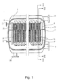
- FIG. 1 shows a component of a plate evaporator apparatus in the form of a closed container or housing 1 shaped as a cylindrical pressure vessel provided with end walls, a plate heat exchanger being arranged within the container.
- the plate heat exchanger comprises two end plates 2 and 3 and a package of heat transferring plates 4 which are clamped conventionally between the end plates.
- the apparatus or housing 1 may be compartmentalized and contain several packages with corresponding end plates placed spaced apart in the individual compartments in an end to end relationship.
- the packages may have a length between the end plates 2, 3 of eg. 2m, a height of eg. 1.5m, and a width normal to the plane of fig. 1 in the order of eg. 1m.
- the end plates 2, 3 as well as the heat transferring plates 4 are carried within the housing, or the compartments of the housing, by a frame which is not shown in the drawing, so that they extend vertically. Spacing members, preferably pressed in the heat transferring plates in a conventional manner, keep the heat transferring plates at a distance from each other, so that plate interspaces to be flowed through by heat exchange fluids are formed.
- a horizontal partition 5 extends within the container 1 all the way around the plate heat exchanger, so that it divides the interior of the container in an upper chamber 6 and a lower chamber 7.
- the upper chamber 6 has an inlet 8 for heat emitting vapour and the lower chamber 7 has an outlet 9 for vapour having been generated in the plate heat exchanger.
- the container 1 has a further outlet 10 from the lower chamber 7, which is intended for liquid having been supplied to but not been evaporated in the plate heat exchanger.
- inlet pipe 11 Through one end wall of the container there are extending one inlet pipe 11 and two outlet pipes 12, the inlet pipe 11 forming an inlet to the plate heat exchanger for liquid to be evaporated therein, and the pipes 12 forming outlets for condensate formed in the plate heat exchanger.
- sealing members of different kinds. These are described below with reference to FIGS. 2 and 3 .
- FIG. 2 shows one side of a heat transferring plate 4 which has a width and a height defining the width and the height of the package of heat transferring plates.
- the heat transferring plate has an elongated rectangular form and is arranged in the container 1 such that its long sides extend vertically and its short sides extend horizontally.
- the partition 5 extends at a certain level in the container 1 from each of the long sides of the heat transferring plates 4 horizontally towards the surrounding wall of the container 1.
- the heat transferring plate 4 On its side shown in FIG. 2 the heat transferring plate 4 has a first seal or gasket 13 extending along the edge of the heat transferring plate upwardly from the level of the partition 5 at one long side of the plate, then along the upper short side of the plate and back downwardly along the other long side of the plate to the level of the partition 5.
- the gasket 13 extends at the long sides of the heat transferring plate horizontally up to the respective parts of the partition 5.
- a second seal or gasket 14 extends in parallel with the upper short side of the heat transferring plate between the vertical portions of the gasket 13, so that an area 15 of the upper part of the heat transferring plate is completely surrounded by the gaskets 13 and 14.
- a closed so called distribution chamber will be formed in the plate interspace in the area 15, which extends across the whole width of the heat transferring plates.
- the heat transferring plate 4 - like all of the heat transferring plates in the plate heat exchanger - has a through opening 16. All of the openings 16 together form a passage 16' through the package of heat transferring plates 4, in the upper part thereof, such as in the upper 1/5 part.
- a pipe 116 such as a plastic material pipe, connected to the inlet 11 and to be discussed below with reference to fig. 5 extends along the passage 16' between the two end plates 2, 3. The pipe 116 communicates both with the previously mentioned inlet 11 ( FIG. 1 ) for liquid to be evaporated and with each of the distribution chambers.
- each heat transferring plate has in the area 15 and close to the gasket 14 four small flow ways in the form of through holes 17 distributed across the width of the plate. Vertically below each of the holes 17 on the opposite side of the gasket 14 there is a further small flow way in the form of a through hole 18. Finally, close to the large opening 16 but below the gasket 14 there are two small flow ways in the form of through holes 19.
- the flow ways have a diameter in the area of 2-3 mm.
- Each heat transferring plate in its lower corner has two through holes 20 and 21, which on the plate side shown in FIG. 2 are surrounded by two annular gaskets 22 and 23, respectively.
- the holes 20 and 21 in the heat transferring plates form two channels through the plate package, which communicate with the outlets 12 of the plate heat exchanger for liquid having been condensed but which are closed by the gaskets 22 and 23, respectively, from connection with the plate interspaces in which these gaskets are arranged.
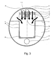
- FIG. 3 shows one side of a heat transferring plate 4 which is intended to be placed behind a heat transferring plate according to FIG. 2 .
- the plate in FIG. 3 has in its upper part, such as in the upper 1/5 of the plate, a relatively large opening 16 and the flow ways in the form of substantially smaller holes 17, 18 and 19.
- the plate in FIG. 3 has through holes 20 and 21 at its lower corners. In these respects the plates in FIG. 2 and FIG. 3 are thus alike.
- the plate according to FIG. 3 has a different arrangement of gaskets than the plate according to FIG. 2 .
- the opening 16 and the two small holes 19 are surrounded by a first gasket 24. Furthermore, there are in the upper part of the plate four horizontally spaced gaskets 25. Each of these surrounds a small area of the plate, in which there are both one hole 17 and one hole 18.
- a gasket 26 extends along the edge of the plate downwardly from the level of the partition 5 at one long side of the plate, then along the lower short side of the plate and again upwardly along the other long side of the plate to the level of the partition 5.
- the gasket 26 extends at the level of the partition 5 horizontally up to the respective portions of the partition 5.
- the holes 20 and 21 at the lower corners of the plate are placed inside, i.e. above, the gasket 26.
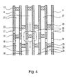
- FIG. 4 shows a section through the upper parts of a number of heat transferring plates, which section is taken along the line IV--IV in FIG. 2 and along a corresponding line IV--IV in FIG. 3 .
- FIG. 4 In every second plate interspace there is shown in FIG. 4 a section through the upper part of a gasket 13 ( FIG. 2 ) and a section through a gasket 14 ( FIG. 2 ). Between the gaskets 13 and 14 there is formed in each such plate interspace a distribution chamber 27 which extends across the whole width of the heat transferring plates 4. The distribution chamber 27 communicates with the passage 16' through the plate package, which is formed by the openings 16 in the plates.
- each evaporation space 28 is closed from connection with the upper chamber 6 in the container 1 by the vertical parts of the gasket 13 ( FIG. 2 ) but communicates with the lower chamber 7 in the container 1 through the slots between the edges of the heat transferring plates--along the lower parts of the plate long sides as well as along the lower short sides of the plates. This is illustrated by means of arrows in FIG. 2 .
- FIG. 4 In each of the rest of the plate interspaces there is shown in FIG. 4 a section through a gasket 25 ( FIG. 3 ), which together with the two heat transferring plates against which it seals forms a transferring chamber 29. Outside the gasket 25 there is formed in the interspace between the two heat transferring plates a condensation space 30.
- the condensation space 30 communicates with the upper chamber 6 in the container 1 through the slots between the two heat transferring plates along the upper short sides thereof as well as along the upper parts of their long sides. This is illustrated by means of arrows in FIG. 3 . Vapour in the chamber 6 thus may flow into each condensation space 30 both from the two sides of the plate package and from above through the interspaces between adjacent gaskets 25.
- Each condensation space 30 is closed by the gasket 26 ( FIG. 3 ) from connection with the lower chamber 7 in the container 1.
- each distribution chamber 27 communicates through opposing holes 17 in two adjacent heat transferring plates with two transferring chambers 29.
- the two said transferring chambers 29 communicate with the evaporation space 28 that is formed between the two heat transferring plates.
- the holes 18 have somewhat larger throughflow area than the holes 17.
- Fig. 5 shows the aforementioned elongated pipe 116 which preferably is removably received in the passage 16' through the package of plates.
- the pipe 116 is provided with through-going apertures 117, 118 and has a length corresponding essentially to the length of the package, i.e. the distance between the endplates 3, 4 shown in fig. 1 ; the apertures 117, 118 may be located in the upper part, such as in the upper half perimeter part, whereby particles settling in the pipe 116 due to the low flow rate will not obstruct the apertures until the point where a significant amount of particles have settled.
- the apertures 117, 118 may each have a diameter in the order of 2 mm, with the diameter of the flow ways 17, 18 being slightly larger than the diameter of the apertures 117, 118.
- Shown in fig. 5 is also a part of the first seal 14 which in the shown embodiment may have projecting parts 110, 119, 120 forming supports supporting the pipe within the passage 16'.
- the projecting parts may be configured to divide the distribution chamber 27 into two portions, an upper one supplying liquid to one set 17, 18 of flow ways and a lower one 27' supplying liquid to other flow ways 19 by dedicated apertures 118. This arrangement may be provided to control the distribution of liquid leaving the distribution chamber 27.
- Fig. 6 is a side view of one embodiment of the pipe 116, showing two segments thereof adapted to be sealingly connected.
- the pipe 116 is preferably closed at one end 150 where a port (not shown) may be provided allowing a tubing to be connected thereto with the aim of flushing the inside of the pipe with a cleaning fluid.
- the distance d between the apertures 117, 118 may be selected to correspond to the distance between the distribution chambers 27 whereby the apertures 117, 118 may be aligned therewith.
- the dimension of the apertures 117, 118 may be increasing towards the closed end 150, or the pipe may be tapering towards the closed end 150.
- the apparatus according to FIG. 1-6 is intended to operate in the following manner.
- Liquid to be evaporated is pumped in a preheated condition through the inlet pipe 11 ( FIG. 1 ) into the pipe 116 through the package of heat transferring plates, that is placed in the passage 16' formed by the openings 16 in the plates. From this pipe 116 the liquid flows through the apertures 117, 118 in the pipe wall and further out into the different distribution chambers 27 ( FIG. 4 ), which extend across the whole width of the heat transferring plates (see the area 15 in FIG. 2 ). From the distribution chambers 27 the liquid flows through the holes 17 in the plates into the various transferring chambers 29 and then through the holes 18 out into the evaporation spaces 28.
- liquid flows into the evaporation spaces 28 directly through the holes 19 from the plate interspaces in which the gaskets 24 ( FIG. 3 ) surround the openings 16 and the holes 19.
- the liquid then runs downwardly in thin layers along the heat transferring plates, covering the opposing surfaces thereof.
- Condensate formed by the heat emitting vapour in the condensation spaces 20 runs downwardly along the heat transferring plates and leaves the condensation spaces through the two channels formed by the holes 20 and 21 in the lower parts of the heat transferring plates. These channels are closed from communication with the evaporation spaces 28 by the gaskets 22 and 23 ( FIG. 2 ). Even uncondensed parts of the heat emitting vapour leave the condensation spaces 30 through said channels and is discharged together with the condensate through the outlets 12 ( FIG. 1 ).
- the holes 18 are somewhat larger than the holes 17.
- the hole sizes are chosen such that during the operation of the apparatus a partial evaporation of evaporation liquid is obtained when the liquid passes through the holes 17.
- the holes 18 are made large enough so that the vapour pressure that will prevail in the transferring chambers 29 shall not exceed the vapour pressure prevailing in the heat emitting vapour in the condensation spaces 30.
- the purpose thereof is to guarantee that upon possible leakage past the gaskets 25 such leakage shall be directed into the transferring chambers 29 and not out of these chambers.
- the apparatus according to the invention is used for the production of fresh water from for instance sea water, it is better if vapour flows into the sea water than if sea water flows into the fresh water.
- each plate has holes 17-19 on both sides (both to the left and to the right) of the opening 16.
- the holes 17-19 may be excluded in every second plate on one side of the opening 16 and in the rest of the plates on the other side of their openings 16.
- the holes 17 may be excluded in every second plate on one side of the opening 16, and the holes 18 and 19 may be excluded on the other side of the opening 16, whereas in each of the rest of the plates the holes 17 may be excluded on said other side and the holes 18 and 19 be excluded on said one side of the opening 16. Even in these cases liquid will be distributed across the whole width of the plates in each of the evaporation spaces 28.
- the sealing members arranged between the heat transferring plates are constituted by elastic rubber or plastic gaskets of the kind usually used in connection with heat transferring plates of thin pressed metal sheet.
- any other suitable kinds of sealing members may be used.
- sealing means could also be chosen permanent interconnection of the heat transferring plates along the lines which in FIGS. 2 and 3 show how different gaskets are extending.
- the heat transferring plates may be pressed in a way such that they abut against each other along these lines in the respective plate interspaces, so that sealing between--possibly interconnection of--the plates is facilitated.
- FIG. 7 shows a flow diagram of a plant in which the described apparatus is included.
- the plant is intended for the production of fresh water from sea water.
- FIG. 5 shows the container 1 with its inlet 8 for heat emitting vapour, its inlet 11 for liquid to be evaporated, i.e. sea water, its outlet 9 for generated vapour, its outlet 10 for concentrated liquid, i.e. sea water having not been evaporated, so called brine, and its outlet 12 for condensate, i.e. fresh water, and uncondensed parts of the heat emitting vapour.
- An additional housing or container 1' may as shown be arranged in an end-to-end relationship with the aforementioned container 1 to provide for a sequential processing of the brine.
- sea water is pumped by means of a pump 31 into the plant. After the pump 31 the sea water is run through a filter 31' and is then divided at 32 in two branch flows. One passes through a heat exchanger 33 and the other through a heat exchanger 34. The branch flows are then united at 35 and are pumped furtheron through another heat exchanger 36 to the inlet 11 of the container 1. The generated vapour leaving the container through the outlet 9 is transferred through a compressor 37 to the inlet 8 for heat emitting vapour.
- a conventional high pressure fan may serve as a compressor.
- So called brine i.e. sea water having not been evaporated in the container 1
- a pump 38 out of the container 1 through its bottom outlet 10 and is divided at 39 in two branch flows.
- One branch flow is returned to the container inlet 11 for liquid to be evaporated, whereas the other branch flow is pumped by means of a pump 40 through the heat exchanger 33 and out of the plant.
- this branch flow emits part of its heat to one of the branch flows of incoming sea water.
- a mixture of fresh water, i.e. condensate from the heat emitting vapour supplied through the inlet 8, and non-condensed residuals of this vapour are removed from the container 1 through the outlet 12.
- a separator 41 the gaseous parts of the mixture are separated, and by means of a vacuum pump 42 they are sucked through the heat exchanger 36 and out of the plant. In the heat exchanger 36 they emit part of their heat to the already partly preheated incoming sea water.
- the fresh water is pumped from the separator 41 by means of a pump 42 through the heat exchanger 34 and out of the plant.
- the fresh water emits part of its heat to a branch flow of the incoming sea water.
- the incoming sea water preferably is preheated almost to a temperature corresponding to its boiling point at the evaporation pressure to be prevailing in the evaporation spaces of the plate heat exchanger.
- the sea water may be preheated so that it has a temperature of 55 DEG C. in the container inlet 11.
- the generated vapour in the container outlet 9 may have a temperature only insignificantly exceeding 55 DEG C. and a pressure of for instance 0,15 bars.
- the vapour may after that be compressed to having in the container inlet 8 and in the chamber 6 a pressure of about 0,19 bars and a temperature of about 59 DEG C.
Landscapes
- Engineering & Computer Science (AREA)
- Physics & Mathematics (AREA)
- Thermal Sciences (AREA)
- Mechanical Engineering (AREA)
- General Engineering & Computer Science (AREA)
- Chemical & Material Sciences (AREA)
- Chemical Kinetics & Catalysis (AREA)
- Ocean & Marine Engineering (AREA)
- Life Sciences & Earth Sciences (AREA)
- Hydrology & Water Resources (AREA)
- Environmental & Geological Engineering (AREA)
- Water Supply & Treatment (AREA)
- Organic Chemistry (AREA)
- Vaporization, Distillation, Condensation, Sublimation, And Cold Traps (AREA)
- Heat Treatment Of Water, Waste Water Or Sewage (AREA)
- Heat-Exchange Devices With Radiators And Conduit Assemblies (AREA)
Abstract
Description
- The present invention concerns a plate evaporator of the falling film type, and a plate evaporator apparatus having such a plate evaporator arranged in a housing.
- More specifically, the plate evaporator of the invention is of the kind comprising a package of substantially vertically arranged heat transferring plates with plate interspaces, every second one of which forms an evaporation space for at least partial evaporation of said liquid and the other plate interspaces forming condensation spaces for at least partial condensation of a heat emitting vapour, and further comprising first seals which in an upper part of said plate interspaces forming evaporation spaces delimit distribution chambers, each of which being in relatively restricted liquid flow communication with at least one evaporation space through flow ways spaced apart along the width of the package, the heat transferring plates having through openings aligned to form a passage which extends through the plate package.
- The invention also concerns the use of such a plate evaporator for the desalination of sea water.
- The invention is primarily concerned with plate evaporators of the aforementioned type where the liquid evaporated in the evaporation spaces is condensed, collected and used in industrial processes not related to the plate evaporator as such, eg. as cooling water in power plants, or for human consumption. The liquid may by way of example be pressed juice with pulp, or sea water.
-
GB 1,299,481 fig. 1b ofGB 1,299,481 - It is a problem with such plate evaporators that particles suspended in the liquid may lead to a clogging of the aforementioned flow ways, affecting the falling film of liquid. In addition, due to the low rate of flow in the individual distribution chambers sedimentation of the suspended particles may also occur in the distribution chambers. Simply increasing the size of the flow ways/through holes to a size that still provides for a falling film may be desirable to reduce clogging; however, making the through holes larger may cause a relatively larger amount of the liquid to flow into those evaporation spaces that are located closest to the inlet, thereby reducing the overall efficiency of the evaporator.
- Attempts to avoid clogging have been made by arranging filters upstream of the plate evaporator. However, in some applications space constraints and/or the nature of the liquid to be evaporated are such that clogging can still not be prevented, even if a filter of some kind is provided. One example is desalination applications where the plate evaporator is used on board a ship or similar places where available space for high grade filters is limited, and where the liquid to be evaporated is sea water. In coast-near areas sea water may contain silt having a particle size of 5-10µ; the sea water may also contain algae of the same particle size. Algae passing through even a fine mesh filter has a tendency to agglomerate, and such agglomerates have often been found to be the cause of clogging, requiring a time consuming and costly dismantling and cleaning of the heat transferring plates.
- A main object of the present invention is to provide a plate evaporator and a plate evaporator apparatus of the initially described kind, in which liquid to be evaporated may still be reliably distributed effectively to the various evaporation spaces in the plate package and where maintenance and cleaning of the plate evaporator is simplified.
- An object of the invention is also to allow for an easy cleaning of the package, where space constraints are such that any dismantling of the package for cleaning would otherwise be difficult.
- The above objects may be obtained in a plate evaporator and a plate evaporator apparatus of the initially defined kind, which is characterized in an elongated pipe connected to the inlet and extending in the passage along a length thereof, the pipe having a peripheral wall with apertures distributed along the length of the pipe and being in flow communication with the distribution chambers, for supplying the liquid to be evaporated from the inlet to the distribution chambers through the apertures. The pipe may be removably mounted in the passage to allow for a cleaning of the pipe at another location, and the apertures may be of increasing size from the end connected to the inlet and towards the opposite end. Preferably, the pipe is placed such that the apertures are aligned with the distribution chambers.
- Preferably, the pipe extends along the full length of the passage and has a first end connected to the inlet and a normally closed openable fluid flow port at the opposite end. This allows for a flushing of the pipe, either in-situ or at another location after removal of the pipe, to flush out any particles that have settled in the pipe.
- According to an embodiment the pipe apertures may be formed exclusively in the upper half perimeter part of the pipe. This provides for an enlarged capacity for settled particles without any significant limitation on the flow through the pipe and into the distribution chambers.
- In the manner shown in
WO91/068318 - According to a preferred embodiment of the invention the apparatus includes a filter for the liquid to be evaporated and located upstream of the pipe, such as at a location outside the housing. This will ensure that only the smallest size particles are collected in the pipe by sedimentation.
- The pipe may be easily elastically bendable, or it may be defined by a series of sealingly interconnected shorter pipe section. This is of particular advantage when the apparatus comprises several housings or packages arranged spaced apart in an end-to-end relationship. In this way the pipe, which may extend for a length of eg. 1-3 m, can be pulled lengthwise out of its receiving passage and free of the package, even when the space between adjoining housings or packages is significantly less than the pipe length, by bending the pipe transversally, or by disassembling the pipe.
- An embodiment of the invention is described below with reference to the accompanying drawing, in which
-
FIG. 1 shows a housing and a plate heat exchanger arranged therein, -
FIG. 2 shows a cross-sectional view along the line II--II inFIG. 1 , -
FIG. 3 shows a cross-sectional view along the line III--III inFIG. 1 , -
FIG. 4 shows a section through the upper part of a plate heat exchanger according to -
FIG. 1 , which section is taken along a line IV--IV inFIG. 2 and a corresponding line IV--IV inFIG. 3 , -
FIG. 5 shows an enlarged part of the plate offig. 2 , -
FIG. 6 shows a partial side view of two segments of the pipe to be inserted in a passage through the plate heat exchanger, and -
FIG. 7 shows a flow diagram of an apparatus for production of fresh water from sea water. -
FIG. 1 shows a component of a plate evaporator apparatus in the form of a closed container orhousing 1 shaped as a cylindrical pressure vessel provided with end walls, a plate heat exchanger being arranged within the container. The plate heat exchanger comprises twoend plates heat transferring plates 4 which are clamped conventionally between the end plates. The apparatus orhousing 1 may be compartmentalized and contain several packages with corresponding end plates placed spaced apart in the individual compartments in an end to end relationship. The packages may have a length between theend plates fig. 1 in the order of eg. 1m. Theend plates heat transferring plates 4 are carried within the housing, or the compartments of the housing, by a frame which is not shown in the drawing, so that they extend vertically. Spacing members, preferably pressed in the heat transferring plates in a conventional manner, keep the heat transferring plates at a distance from each other, so that plate interspaces to be flowed through by heat exchange fluids are formed. - A
horizontal partition 5 extends within thecontainer 1 all the way around the plate heat exchanger, so that it divides the interior of the container in anupper chamber 6 and alower chamber 7. Theupper chamber 6 has aninlet 8 for heat emitting vapour and thelower chamber 7 has anoutlet 9 for vapour having been generated in the plate heat exchanger. At its bottom thecontainer 1 has afurther outlet 10 from thelower chamber 7, which is intended for liquid having been supplied to but not been evaporated in the plate heat exchanger. - Through one end wall of the container there are extending one
inlet pipe 11 and twooutlet pipes 12, theinlet pipe 11 forming an inlet to the plate heat exchanger for liquid to be evaporated therein, and thepipes 12 forming outlets for condensate formed in the plate heat exchanger. - Between the
heat transferring plates 4 there are arranged sealing members of different kinds. These are described below with reference toFIGS. 2 and3 . -
FIG. 2 shows one side of aheat transferring plate 4 which has a width and a height defining the width and the height of the package of heat transferring plates. As can be seen the heat transferring plate has an elongated rectangular form and is arranged in thecontainer 1 such that its long sides extend vertically and its short sides extend horizontally. Thepartition 5 extends at a certain level in thecontainer 1 from each of the long sides of the heat transferringplates 4 horizontally towards the surrounding wall of thecontainer 1. - On its side shown in
FIG. 2 theheat transferring plate 4 has a first seal orgasket 13 extending along the edge of the heat transferring plate upwardly from the level of thepartition 5 at one long side of the plate, then along the upper short side of the plate and back downwardly along the other long side of the plate to the level of thepartition 5. As can be seen fromFIG. 2 , thegasket 13 extends at the long sides of the heat transferring plate horizontally up to the respective parts of thepartition 5. - A second seal or
gasket 14 extends in parallel with the upper short side of the heat transferring plate between the vertical portions of thegasket 13, so that anarea 15 of the upper part of the heat transferring plate is completely surrounded by thegaskets gaskets FIG. 2 as well as an adjacent plate in the plate heat exchanger, a closed so called distribution chamber will be formed in the plate interspace in thearea 15, which extends across the whole width of the heat transferring plates. - In the
area 15 the heat transferring plate 4 - like all of the heat transferring plates in the plate heat exchanger - has a throughopening 16. All of theopenings 16 together form a passage 16' through the package ofheat transferring plates 4, in the upper part thereof, such as in the upper 1/5 part. Apipe 116, such as a plastic material pipe, connected to theinlet 11 and to be discussed below with reference tofig. 5 extends along the passage 16' between the twoend plates pipe 116 communicates both with the previously mentioned inlet 11 (FIG. 1 ) for liquid to be evaporated and with each of the distribution chambers. - In addition to the
opening 16 each heat transferring plate has in thearea 15 and close to thegasket 14 four small flow ways in the form of throughholes 17 distributed across the width of the plate. Vertically below each of theholes 17 on the opposite side of thegasket 14 there is a further small flow way in the form of a throughhole 18. Finally, close to thelarge opening 16 but below thegasket 14 there are two small flow ways in the form of throughholes 19. The flow ways have a diameter in the area of 2-3 mm. - Each heat transferring plate in its lower corner has two through
holes FIG. 2 are surrounded by twoannular gaskets 22 and 23, respectively. Theholes outlets 12 of the plate heat exchanger for liquid having been condensed but which are closed by thegaskets 22 and 23, respectively, from connection with the plate interspaces in which these gaskets are arranged. -
FIG. 3 shows one side of aheat transferring plate 4 which is intended to be placed behind a heat transferring plate according toFIG. 2 . As can be seen, the plate inFIG. 3 has in its upper part, such as in the upper 1/5 of the plate, a relativelylarge opening 16 and the flow ways in the form of substantiallysmaller holes FIG. 3 has throughholes FIG. 2 andFIG. 3 are thus alike. The plate according toFIG. 3 , however, has a different arrangement of gaskets than the plate according toFIG. 2 . - In the upper part of the plate in
FIG. 3 theopening 16 and the twosmall holes 19 are surrounded by afirst gasket 24. Furthermore, there are in the upper part of the plate four horizontally spacedgaskets 25. Each of these surrounds a small area of the plate, in which there are both onehole 17 and onehole 18. - In the lower part of the plate in
FIG. 3 agasket 26 extends along the edge of the plate downwardly from the level of thepartition 5 at one long side of the plate, then along the lower short side of the plate and again upwardly along the other long side of the plate to the level of thepartition 5. As can be seen, thegasket 26 extends at the level of thepartition 5 horizontally up to the respective portions of thepartition 5. Theholes gasket 26. -
FIG. 4 shows a section through the upper parts of a number of heat transferring plates, which section is taken along the line IV--IV inFIG. 2 and along a corresponding line IV--IV inFIG. 3 . - In every second plate interspace there is shown in
FIG. 4 a section through the upper part of a gasket 13 (FIG. 2 ) and a section through a gasket 14 (FIG. 2 ). Between thegaskets distribution chamber 27 which extends across the whole width of theheat transferring plates 4. Thedistribution chamber 27 communicates with the passage 16' through the plate package, which is formed by theopenings 16 in the plates. - Below the
gasket 14 there is formed in each of these plate interspaces anevaporation space 28 in which liquid is to be evaporated. Eachevaporation space 28 is closed from connection with theupper chamber 6 in thecontainer 1 by the vertical parts of the gasket 13 (FIG. 2 ) but communicates with thelower chamber 7 in thecontainer 1 through the slots between the edges of the heat transferring plates--along the lower parts of the plate long sides as well as along the lower short sides of the plates. This is illustrated by means of arrows inFIG. 2 . - In each of the rest of the plate interspaces there is shown in
FIG. 4 a section through a gasket 25 (FIG. 3 ), which together with the two heat transferring plates against which it seals forms a transferringchamber 29. Outside thegasket 25 there is formed in the interspace between the two heat transferring plates acondensation space 30. Thecondensation space 30 communicates with theupper chamber 6 in thecontainer 1 through the slots between the two heat transferring plates along the upper short sides thereof as well as along the upper parts of their long sides. This is illustrated by means of arrows inFIG. 3 . Vapour in thechamber 6 thus may flow into eachcondensation space 30 both from the two sides of the plate package and from above through the interspaces betweenadjacent gaskets 25. - Each
condensation space 30 is closed by the gasket 26 (FIG. 3 ) from connection with thelower chamber 7 in thecontainer 1. - All of the plate interspaces forming
condensation spaces 30, as well as theupper chamber 6 in thecontainer 1, are closed by the gaskets 24 (FIG. 3 ) from connection with the passage 16' through the plate package, which is formed by theopenings 16 in the heat transferring plates. - As illustrated by arrows in
FIG. 4 , eachdistribution chamber 27 communicates through opposingholes 17 in two adjacent heat transferring plates with two transferringchambers 29. Through opposingholes 18 in the same heat transferring plates the two said transferringchambers 29 communicate with theevaporation space 28 that is formed between the two heat transferring plates. Theholes 18 have somewhat larger throughflow area than theholes 17. -
Fig. 5 shows the aforementionedelongated pipe 116 which preferably is removably received in the passage 16' through the package of plates. Thepipe 116 is provided with through-goingapertures endplates fig. 1 ; theapertures pipe 116 due to the low flow rate will not obstruct the apertures until the point where a significant amount of particles have settled. - By way of example, the
apertures flow ways apertures - Shown in
fig. 5 is also a part of thefirst seal 14 which in the shown embodiment may have projectingparts distribution chamber 27 into two portions, an upper one supplying liquid to oneset other flow ways 19 bydedicated apertures 118. This arrangement may be provided to control the distribution of liquid leaving thedistribution chamber 27. -
Fig. 6 is a side view of one embodiment of thepipe 116, showing two segments thereof adapted to be sealingly connected. Thepipe 116 is preferably closed at oneend 150 where a port (not shown) may be provided allowing a tubing to be connected thereto with the aim of flushing the inside of the pipe with a cleaning fluid. The distance d between theapertures distribution chambers 27 whereby theapertures apertures closed end 150, or the pipe may be tapering towards theclosed end 150. - The apparatus according to
FIG. 1-6 is intended to operate in the following manner. - Liquid to be evaporated is pumped in a preheated condition through the inlet pipe 11 (
FIG. 1 ) into thepipe 116 through the package of heat transferring plates, that is placed in the passage 16' formed by theopenings 16 in the plates. From thispipe 116 the liquid flows through theapertures FIG. 4 ), which extend across the whole width of the heat transferring plates (see thearea 15 inFIG. 2 ). From thedistribution chambers 27 the liquid flows through theholes 17 in the plates into the various transferringchambers 29 and then through theholes 18 out into theevaporation spaces 28. Simultaneously, liquid flows into theevaporation spaces 28 directly through theholes 19 from the plate interspaces in which the gaskets 24 (FIG. 3 ) surround theopenings 16 and theholes 19. In theevaporation spaces 28 the liquid then runs downwardly in thin layers along the heat transferring plates, covering the opposing surfaces thereof. - Simultaneously there is supplied to the
upper chamber 6 in thecontainer 1 through the inlet 8 a heat emitting vapour which flows into thecondensation spaces 30 through the slots between the edges of the heat transferring plates, as illustrated inFIG. 3 . The heat emitting vapour condensates in thecondensation spaces 30 upon its contact with the heat transferring plates to which it thus emits heat. This heat causes evaporation of the liquid running downwardly along the opposite sides of the plates in theevaporation spaces 28. Vapour formed in theevaporation spaces 28 leaves and flows out into thelower chamber 7 of thecontainer 1 both sidewise and downwardly, as illustrated by means of arrows inFIG. 2 . The generated vapour leaves thechamber 7 through theoutlet 9, whereas unevaporated liquid is collected at the bottom of the container and is discharged--continuously or intermittentlythrough the bottom outlet 10 (FIG. 1 ). - Condensate formed by the heat emitting vapour in the
condensation spaces 20 runs downwardly along the heat transferring plates and leaves the condensation spaces through the two channels formed by theholes evaporation spaces 28 by thegaskets 22 and 23 (FIG. 2 ). Even uncondensed parts of the heat emitting vapour leave thecondensation spaces 30 through said channels and is discharged together with the condensate through the outlets 12 (FIG. 1 ). - As mentioned previously, the
holes 18 are somewhat larger than theholes 17. The hole sizes are chosen such that during the operation of the apparatus a partial evaporation of evaporation liquid is obtained when the liquid passes through theholes 17. Theholes 18 are made large enough so that the vapour pressure that will prevail in the transferringchambers 29 shall not exceed the vapour pressure prevailing in the heat emitting vapour in thecondensation spaces 30. The purpose thereof is to guarantee that upon possible leakage past thegaskets 25 such leakage shall be directed into the transferringchambers 29 and not out of these chambers. Particularly if the apparatus according to the invention is used for the production of fresh water from for instance sea water, it is better if vapour flows into the sea water than if sea water flows into the fresh water. - In the embodiment of the
heat transferring plates 4 shown inFIGS. 2 and3 each plate has holes 17-19 on both sides (both to the left and to the right) of theopening 16. If desired, the holes 17-19 may be excluded in every second plate on one side of theopening 16 and in the rest of the plates on the other side of theiropenings 16. Alternatively, theholes 17 may be excluded in every second plate on one side of theopening 16, and theholes opening 16, whereas in each of the rest of the plates theholes 17 may be excluded on said other side and theholes opening 16. Even in these cases liquid will be distributed across the whole width of the plates in each of theevaporation spaces 28. - It has been assumed above that the sealing members arranged between the heat transferring plates are constituted by elastic rubber or plastic gaskets of the kind usually used in connection with heat transferring plates of thin pressed metal sheet. Of course, any other suitable kinds of sealing members may be used. As sealing means could also be chosen permanent interconnection of the heat transferring plates along the lines which in
FIGS. 2 and3 show how different gaskets are extending. The heat transferring plates may be pressed in a way such that they abut against each other along these lines in the respective plate interspaces, so that sealing between--possibly interconnection of--the plates is facilitated. -
FIG. 7 shows a flow diagram of a plant in which the described apparatus is included. The plant is intended for the production of fresh water from sea water. Thus,FIG. 5 shows thecontainer 1 with itsinlet 8 for heat emitting vapour, itsinlet 11 for liquid to be evaporated, i.e. sea water, itsoutlet 9 for generated vapour, itsoutlet 10 for concentrated liquid, i.e. sea water having not been evaporated, so called brine, and itsoutlet 12 for condensate, i.e. fresh water, and uncondensed parts of the heat emitting vapour. An additional housing or container 1' may as shown be arranged in an end-to-end relationship with theaforementioned container 1 to provide for a sequential processing of the brine. Where the spacing d between the twohousings 1, 1' is smaller than the length of thepipe 116 removal of thepipe 116 for cleaning may be facilitated by making the pipe bendable or separable into segment as discussed with reference tofig. 6 whereby thepipe 116 may be pulled out from the package of the onehousing 1 towards the end wall of the adjoining housing 1' and removed sideways from the space between the twohousings 1, 1'. By bendable is meant herein elastically bendable such that thepipe 116 will return to its original shape when an external bending force is released. - In operation, sea water is pumped by means of a
pump 31 into the plant. After thepump 31 the sea water is run through a filter 31' and is then divided at 32 in two branch flows. One passes through aheat exchanger 33 and the other through aheat exchanger 34. The branch flows are then united at 35 and are pumped furtheron through anotherheat exchanger 36 to theinlet 11 of thecontainer 1. The generated vapour leaving the container through theoutlet 9 is transferred through acompressor 37 to theinlet 8 for heat emitting vapour. A conventional high pressure fan may serve as a compressor. - So called brine, i.e. sea water having not been evaporated in the
container 1, is pumped by means of apump 38 out of thecontainer 1 through itsbottom outlet 10 and is divided at 39 in two branch flows. One branch flow is returned to thecontainer inlet 11 for liquid to be evaporated, whereas the other branch flow is pumped by means of apump 40 through theheat exchanger 33 and out of the plant. In theheat exchanger 33 this branch flow emits part of its heat to one of the branch flows of incoming sea water. - A mixture of fresh water, i.e. condensate from the heat emitting vapour supplied through the
inlet 8, and non-condensed residuals of this vapour are removed from thecontainer 1 through theoutlet 12. In aseparator 41 the gaseous parts of the mixture are separated, and by means of avacuum pump 42 they are sucked through theheat exchanger 36 and out of the plant. In theheat exchanger 36 they emit part of their heat to the already partly preheated incoming sea water. - The fresh water is pumped from the
separator 41 by means of apump 42 through theheat exchanger 34 and out of the plant. In theheat exchanger 34 the fresh water emits part of its heat to a branch flow of the incoming sea water. - In the described plant the incoming sea water preferably is preheated almost to a temperature corresponding to its boiling point at the evaporation pressure to be prevailing in the evaporation spaces of the plate heat exchanger. For instance, the sea water may be preheated so that it has a temperature of 55 DEG C. in the
container inlet 11. The generated vapour in thecontainer outlet 9 may have a temperature only insignificantly exceeding 55 DEG C. and a pressure of forinstance 0,15 bars. The vapour may after that be compressed to having in thecontainer inlet 8 and in the chamber 6 a pressure of about 0,19 bars and a temperature of about 59 DEG C. - From the description above follows that, although various embodiments of the invention have been described and shown, the invention is not restricted thereto, but may also be embodied in other ways within the scope of the subject-matter defined in the following claims.
Claims (16)
- A plate evaporator apparatus of the falling film type comprising a housing having an inlet (11) for liquid to be evaporated and having mounted therein a package of substantially vertically arranged heat transferring plates (4) with plate interspaces, every second one of which forms an evaporation space (28) for at least partial evaporation of said liquid and the other plate interspaces forming condensation spaces (30) for at least partial condensation of a heat emitting vapour, and further comprising first seals (13, 14) which in an upper part of said plate interspaces forming evaporation spaces (28) delimit distribution chambers (27), each of which being in liquid flow communication with at least one evaporation space (28) by flow ways (17, 18) spaced apart along the width of the package, the heat transferring plates (4) having in an upper part through openings (16) aligned to form a passage (16') which extends through the plate package,
characterized in an elongated pipe (116) connected to the inlet (11) and extending in the passage (16') along a length thereof, the pipe (116) having a peripheral wall with apertures (117, 118) distributed along the length of the pipe (116) and being in flow communication with the distribution chambers (27), for supplying the liquid to be evaporated from the inlet (11) to the distribution chambers (27) through the apertures (117, 118). - The plate evaporator apparatus according to the preceding claim, the pipe (116) extending along the full length of the passage (16'), the pipe (116) having a first end connected to the inlet (11) and having a normally closed openable fluid flow port at a second end (150).
- The plate evaporator apparatus according to any of the preceding claims, including supports (110, 119, 120) arranged along the periphery of the through openings (16), for supporting the pipe (116) inside the through openings (16), said supports optionally being integrally formed with said first seals (14).
- The plate evaporator apparatus according to any of the preceding claims, said apertures (117, 118) being formed exclusively in the upper half perimeter part of said pipe (116).
- The plate evaporator apparatus according to any of the preceding claims, said apparatus comprising a plurality of said housings (1, 1') or packages arranged spaced apart in an end-to-end relationship, the pipe (116) being defined by sealingly connected shorter pipe sections and/or the pipe being bendable.
- The plate evaporator apparatus according to any of the preceding claims, said apparatus including a filter (31') for said liquid to be evaporated being located upstream of the pipe (116).
- Use of the plate evaporator apparatus of the falling film type according to any of the previous claims, for the desalination by evaporation of sea water supplied to said inlet (11).
- A plate evaporator of the falling film type comprising a package of substantially vertically arranged heat transferring plates (4) with plate interspaces, every second one of which forms an evaporation space (28) for at least partial evaporation of a liquid and the other plate interspaces forming condensation spaces (30) for at least partial condensation of a heat emitting vapour, and further comprising first seals (13, 14) which in an upper part of said plate interspaces forming evaporation spaces (28) delimit distribution chambers (27), each of which being in liquid flow communication with at least one evaporation space (28) by flow ways (17, 18) spaced apart along the width of the package, the heat transferring plates (4) having in an upper part through openings (16) aligned to form a passage (16') which extends through the plate package,
characterized in an elongated pipe (116) connectable to a supply (11) of the liquid and extending in the passage (16') along a length thereof, the pipe (116) having a peripheral wall with apertures (117, 118) distributed along the length of the pipe (116) and being in flow communication with the distribution chambers (27), for supplying the liquid to be evaporated from the inlet (11) to the distribution chambers (27) through the apertures (117, 118). - The plate evaporator according to the preceding claim, said pipe extending along the full length of said passage (16'), the pipe having a first end connected to said inlet (11) and having a normally closed openable port at a second end.
- The plate evaporator according to any of the preceding claims 8-9, including supports (110, 119, 120) arranged along the periphery of said through openings (16), for supporting said pipe (116) inside said through openings (16), said supports optionally being integrally formed with said first seals.
- The plate evaporator according to any of the preceding claims 8-10, the apertures (117, 118) being formed exclusively in the upper half perimeter part of said pipe (116).
- The plate evaporator according to any of the preceding claims 8-11, wherein at least two second seals (25) are arranged in an upper part of each condensation space (30), horizontally spaced from each other along the heat transferring plates (4), each of said second seals delimiting between the heat transferring plates (4) a transferring chamber (29) that is closed from connection with other parts of the condensation space (30), the condensation spaces (30) communicate with the surrounding of the plate package through the gaps formed between said second seals (25) for receiving heat emitting vapour from above, and the heat transferring plates (4) have through holes (17, 18) providing said flow communication with the transferring chambers, for each transferring chamber (29) at least one first hole (17) connecting the transferring chamber (29) with a distribution chamber (27) and at least one second hole (18) connecting the transferring chamber (29) with an evaporation space (28).
- The plate evaporator according to the previous claim, wherein said at least every second heat transferring plate (4) has said through holes (17, 18) arranged in pairs, said first hole (17) in a pair of holes connecting a transferring chamber (29) with a distribution chamber (27) and said second hole (18) connecting the same transferring chamber (29) with an evaporation space (28).
- The plate evaporator according to claim 12 or 13, wherein each heat transferring plate (4) has vertical and horizontal edge portions, each of the distribution chambers (27) extends horizontally between the vertical edge portions of the heat transferring plates and the inlet passage (16') for evaporation liquid extends through the plate package substantially in the middle between said edge portions.
- The plate evaporator according to any of claims 12-14, wherein each heat transferring plate (4) has vertical and horizontal edge portions, and the condensation spaces (30) communicate directly with the surrounding of the plate package along the vertical as well as the upper horizontal edges of the heat transferring plates.
- The plate evaporator according to any of claims 12-15, wherein said first hole (17) is smaller than said second hole (18).
Priority Applications (12)
| Application Number | Priority Date | Filing Date | Title |
|---|---|---|---|
| ES11182336.5T ES2585594T3 (en) | 2011-09-22 | 2011-09-22 | A plate evaporator of the falling film type and a plate evaporator apparatus having such a plate evaporator arranged in a housing |
| DK11182336.5T DK2573495T3 (en) | 2011-09-22 | 2011-09-22 | Thin plate evaporator of "falling film" scheme and plate evaporator device with such plate evaporator that is located in the house |
| EP11182336.5A EP2573495B1 (en) | 2011-09-22 | 2011-09-22 | A plate evaporator of the falling film type, and a plate evaporator apparatus having such a plate evaporator arranged in a housing |
| CN201280046366.1A CN103827620B (en) | 2011-09-22 | 2012-09-13 | The plate-type evaporator of film-lowering type and shell are provided with the plate-type evaporator device of this plate-type evaporator |
| CA2846774A CA2846774C (en) | 2011-09-22 | 2012-09-13 | A plate evaporator of the falling film type, and a plate evaporator apparatus having such a plate evaporator arranged in a housing |
| US14/346,569 US9072985B2 (en) | 2011-09-22 | 2012-09-13 | Plate evaporator of the falling film type, and a plate evaporator apparatus having such a plate evaporator arranged in a housing |
| RU2014115975/06A RU2564387C1 (en) | 2011-09-22 | 2012-09-13 | Plate evaporator with falling film, and design of plate evaporator containing such plate evaporator installed in casing |
| AU2012311682A AU2012311682B2 (en) | 2011-09-22 | 2012-09-13 | A plate evaporator of the falling film type, and a plate evaporator apparatus having such a plate evaporator arranged in a housing |
| JP2014531175A JP5703421B2 (en) | 2011-09-22 | 2012-09-13 | Plate-type evaporator device having a falling film-type plate-type evaporative opening and closing device and such a plate-type evaporator arranged in a housing |
| PCT/EP2012/067965 WO2013041441A2 (en) | 2011-09-22 | 2012-09-13 | A plate evaporator of the falling film type, and a plate evaporator apparatus having such a plate evaporator arranged in a housing |
| KR1020147007485A KR101596181B1 (en) | 2011-09-22 | 2012-09-13 | A plate evaporator of the falling film type, and a plate evaporator apparatus having such a plate evaporator arranged in a housing |
| BR112014006442-3A BR112014006442B1 (en) | 2011-09-22 | 2012-09-13 | degasser type plate evaporator apparatus, and use of degasser type plate evaporator apparatus |
Applications Claiming Priority (1)
| Application Number | Priority Date | Filing Date | Title |
|---|---|---|---|
| EP11182336.5A EP2573495B1 (en) | 2011-09-22 | 2011-09-22 | A plate evaporator of the falling film type, and a plate evaporator apparatus having such a plate evaporator arranged in a housing |
Publications (2)
| Publication Number | Publication Date |
|---|---|
| EP2573495A1 true EP2573495A1 (en) | 2013-03-27 |
| EP2573495B1 EP2573495B1 (en) | 2016-07-06 |
Family
ID=46851486
Family Applications (1)
| Application Number | Title | Priority Date | Filing Date |
|---|---|---|---|
| EP11182336.5A Not-in-force EP2573495B1 (en) | 2011-09-22 | 2011-09-22 | A plate evaporator of the falling film type, and a plate evaporator apparatus having such a plate evaporator arranged in a housing |
Country Status (12)
| Country | Link |
|---|---|
| US (1) | US9072985B2 (en) |
| EP (1) | EP2573495B1 (en) |
| JP (1) | JP5703421B2 (en) |
| KR (1) | KR101596181B1 (en) |
| CN (1) | CN103827620B (en) |
| AU (1) | AU2012311682B2 (en) |
| BR (1) | BR112014006442B1 (en) |
| CA (1) | CA2846774C (en) |
| DK (1) | DK2573495T3 (en) |
| ES (1) | ES2585594T3 (en) |
| RU (1) | RU2564387C1 (en) |
| WO (1) | WO2013041441A2 (en) |
Cited By (3)
| Publication number | Priority date | Publication date | Assignee | Title |
|---|---|---|---|---|
| WO2016000812A1 (en) * | 2014-07-01 | 2016-01-07 | Linde Aktiengesellschaft | Block-in-shell heat exchanger |
| EP3418666A4 (en) * | 2016-02-17 | 2019-11-06 | IHI Corporation | THERMAL TREATMENT APPARATUS |
| CN119983869A (en) * | 2025-03-26 | 2025-05-13 | 江苏巨衡机械有限公司 | Intelligent heat exchange device and method for heat storage boiler |
Families Citing this family (13)
| Publication number | Priority date | Publication date | Assignee | Title |
|---|---|---|---|---|
| ES2717523T3 (en) * | 2015-12-22 | 2019-06-21 | Alfa Laval Corp Ab | A distillation plant with removable plate heat exchangers |
| CN105928401B (en) * | 2016-06-15 | 2017-11-14 | 清华大学 | A kind of detachable plate type phase transition of vacuum device |
| KR102071320B1 (en) * | 2016-12-07 | 2020-01-30 | 한국전자통신연구원 | Apparatus for evaporative desalinating salt water using solar energy |
| CN106839830A (en) * | 2017-01-17 | 2017-06-13 | 扬州建元生物科技有限公司 | Multipaths detachable plate type autoclave evaporator |
| IT201700105423A1 (en) * | 2017-09-21 | 2017-12-21 | Ur Fog S R L | Fog device |
| CN107510949A (en) * | 2017-09-26 | 2017-12-26 | 深圳市蓝石环保科技有限公司 | A kind of MVR vapo(u)rization systems |
| US11505475B2 (en) * | 2017-11-01 | 2022-11-22 | Ecovap, Inc. | Evaporation panel assemblies, systems, and methods |
| CN110203988B (en) * | 2018-10-29 | 2021-01-29 | 山东大学 | A vacuum system and seawater desalination system |
| CN109422316B (en) * | 2018-10-29 | 2020-05-08 | 山东大学 | A tube-plate heat exchange device and its seawater desalination system |
| CN110510686B (en) * | 2018-10-29 | 2021-01-29 | 山东大学 | Temperature-equalizing plate and seawater desalination system thereof |
| EP4071433B1 (en) * | 2020-01-14 | 2023-12-20 | Daikin Industries, Ltd. | Shell-and-plate heat exchanger |
| BE1029506B1 (en) * | 2021-05-25 | 2023-01-23 | Ind Advanced Services Fze | Heat exchanger with vapor extractors |
| CN116947140B (en) * | 2023-08-15 | 2024-06-14 | 中国矿业大学 | A cross-flow falling film evaporation condensation desalination device |
Citations (4)
| Publication number | Priority date | Publication date | Assignee | Title |
|---|---|---|---|---|
| GB1299481A (en) | 1970-05-06 | 1972-12-13 | Apv Co Ltd | Improvements in or relating to evaporators |
| WO1991006818A1 (en) | 1989-11-02 | 1991-05-16 | Alfa-Laval Desalt A/S | Plate evaporator |
| WO1993014363A1 (en) * | 1992-01-21 | 1993-07-22 | Alfa-Laval Thermal Ab | Distribution pattern of a plate heat exchanger |
| WO2009062738A1 (en) * | 2007-11-14 | 2009-05-22 | Swep International Ab | Distribution pipe |
Family Cites Families (16)
| Publication number | Priority date | Publication date | Assignee | Title |
|---|---|---|---|---|
| DE937328C (en) | 1952-10-31 | 1956-01-05 | Ahlborn E Ag | Steam-powered plate heat exchanger for liquids, especially milk |
| US3735793A (en) * | 1971-05-04 | 1973-05-29 | Apv Co Ltd | Plate evaporators |
| US4303124A (en) * | 1979-06-04 | 1981-12-01 | The A.P.V. Company Limited | Plate heat exchanger |
| US4287945A (en) * | 1979-07-03 | 1981-09-08 | The A.P.V. Company Limited | Plate heat exchanger |
| US5597453A (en) * | 1992-10-16 | 1997-01-28 | Superstill Technology, Inc. | Apparatus and method for vapor compression distillation device |
| IL107850A0 (en) | 1992-12-07 | 1994-04-12 | Multistack Int Ltd | Improvements in plate heat exchangers |
| DE4422178A1 (en) | 1993-07-03 | 1995-01-12 | Flitsch E Gmbh & Co | Device for distributing coolant in an evaporator |
| JPH11148797A (en) * | 1997-11-19 | 1999-06-02 | Yasumasa Akazawa | Method for cleaning air supply passage and device for the same |
| RU2127853C1 (en) * | 1998-03-02 | 1999-03-20 | Закрытое акционерное общество "Стройтрансгаз" | Installation for hot-water heating and/or hot water supply |
| SE516416C2 (en) | 2000-05-19 | 2002-01-15 | Alfa Laval Ab | Plate package, heat transfer plate, plate heat exchanger and use of heat transfer plate |
| US7017656B2 (en) | 2001-05-24 | 2006-03-28 | Honeywell International, Inc. | Heat exchanger with manifold tubes for stiffening and load bearing |
| US20030010483A1 (en) * | 2001-07-13 | 2003-01-16 | Yasuo Ikezaki | Plate type heat exchanger |
| MXPA04008504A (en) * | 2002-03-02 | 2005-07-13 | R Stout Timothy | Structure for multiple-effect distillation using tubes or plates. |
| RU2226656C1 (en) * | 2002-08-22 | 2004-04-10 | Федеральное Государственное унитарное предприятие "Государственное научно-производственное предприятие "Сплав" | Water heating and/or hot water supply unit |
| US8240367B2 (en) * | 2007-06-28 | 2012-08-14 | Exxonmobil Research And Engineering Company | Plate heat exchanger port insert and method for alleviating vibrations in a heat exchanger |
| KR101094469B1 (en) * | 2009-06-09 | 2011-12-19 | 서진욱 | Plate heat exchanger with distributor |
-
2011
- 2011-09-22 DK DK11182336.5T patent/DK2573495T3/en active
- 2011-09-22 EP EP11182336.5A patent/EP2573495B1/en not_active Not-in-force
- 2011-09-22 ES ES11182336.5T patent/ES2585594T3/en active Active
-
2012
- 2012-09-13 US US14/346,569 patent/US9072985B2/en not_active Expired - Fee Related
- 2012-09-13 RU RU2014115975/06A patent/RU2564387C1/en active
- 2012-09-13 KR KR1020147007485A patent/KR101596181B1/en not_active Expired - Fee Related
- 2012-09-13 BR BR112014006442-3A patent/BR112014006442B1/en not_active IP Right Cessation
- 2012-09-13 WO PCT/EP2012/067965 patent/WO2013041441A2/en not_active Ceased
- 2012-09-13 CN CN201280046366.1A patent/CN103827620B/en not_active Expired - Fee Related
- 2012-09-13 JP JP2014531175A patent/JP5703421B2/en not_active Expired - Fee Related
- 2012-09-13 AU AU2012311682A patent/AU2012311682B2/en not_active Ceased
- 2012-09-13 CA CA2846774A patent/CA2846774C/en not_active Expired - Fee Related
Patent Citations (5)
| Publication number | Priority date | Publication date | Assignee | Title |
|---|---|---|---|---|
| GB1299481A (en) | 1970-05-06 | 1972-12-13 | Apv Co Ltd | Improvements in or relating to evaporators |
| WO1991006818A1 (en) | 1989-11-02 | 1991-05-16 | Alfa-Laval Desalt A/S | Plate evaporator |
| US5203406A (en) * | 1989-11-02 | 1993-04-20 | Alfa-Laval Desalt A/S | Plate evaporator |
| WO1993014363A1 (en) * | 1992-01-21 | 1993-07-22 | Alfa-Laval Thermal Ab | Distribution pattern of a plate heat exchanger |
| WO2009062738A1 (en) * | 2007-11-14 | 2009-05-22 | Swep International Ab | Distribution pipe |
Cited By (4)
| Publication number | Priority date | Publication date | Assignee | Title |
|---|---|---|---|---|
| WO2016000812A1 (en) * | 2014-07-01 | 2016-01-07 | Linde Aktiengesellschaft | Block-in-shell heat exchanger |
| CN106471326A (en) * | 2014-07-01 | 2017-03-01 | 林德股份公司 | block-in-shell heat exchanger |
| EP3418666A4 (en) * | 2016-02-17 | 2019-11-06 | IHI Corporation | THERMAL TREATMENT APPARATUS |
| CN119983869A (en) * | 2025-03-26 | 2025-05-13 | 江苏巨衡机械有限公司 | Intelligent heat exchange device and method for heat storage boiler |
Also Published As
| Publication number | Publication date |
|---|---|
| CN103827620B (en) | 2016-10-12 |
| CN103827620A (en) | 2014-05-28 |
| CA2846774A1 (en) | 2013-03-28 |
| JP2014531568A (en) | 2014-11-27 |
| RU2564387C1 (en) | 2015-09-27 |
| AU2012311682A1 (en) | 2014-04-10 |
| KR101596181B1 (en) | 2016-02-19 |
| WO2013041441A2 (en) | 2013-03-28 |
| US9072985B2 (en) | 2015-07-07 |
| AU2012311682B2 (en) | 2015-10-22 |
| DK2573495T3 (en) | 2016-09-26 |
| US20140251550A1 (en) | 2014-09-11 |
| BR112014006442A2 (en) | 2017-03-28 |
| CA2846774C (en) | 2016-04-05 |
| WO2013041441A3 (en) | 2013-09-19 |
| EP2573495B1 (en) | 2016-07-06 |
| KR20140066727A (en) | 2014-06-02 |
| BR112014006442B1 (en) | 2020-12-08 |
| JP5703421B2 (en) | 2015-04-22 |
| ES2585594T3 (en) | 2016-10-06 |
Similar Documents
| Publication | Publication Date | Title |
|---|---|---|
| EP2573495B1 (en) | A plate evaporator of the falling film type, and a plate evaporator apparatus having such a plate evaporator arranged in a housing | |
| EP0497880B1 (en) | Plate evaporator | |
| US5232557A (en) | Heat transfer plates evaporation and condensation apparatus | |
| JP5832922B2 (en) | Heat exchanger equipment | |
| US9011679B2 (en) | Apparatus for waste water treatment | |
| KR20070118610A (en) | Plate heat exchanger | |
| KR20180095058A (en) | Distillation plant with removable plate heat exchanger | |
| KR101328635B1 (en) | Sediment removing apparatus for plant intake water channel or drainage water channel | |
| CN115638684A (en) | A multi-stage heat exchange separator | |
| CN110772816A (en) | Material evaporator with liquid level balancing function | |
| CN211302111U (en) | Material cascade evaporation and concentration device | |
| CN210645380U (en) | Solid-liquid separation device for high-capacity pilot production | |
| WO2017144989A2 (en) | A modular system for heat exchangers | |
| SE464939B (en) | Plate heat exchanger for evaporation and condensation arranged in a container in which a partition forms two chambers, the sealing members of the plates being arranged in such a manner that both sets of passages are connected to their respective chamber |
Legal Events
| Date | Code | Title | Description |
|---|---|---|---|
| PUAI | Public reference made under article 153(3) epc to a published international application that has entered the european phase |
Free format text: ORIGINAL CODE: 0009012 |
|
| AK | Designated contracting states |
Kind code of ref document: A1 Designated state(s): AL AT BE BG CH CY CZ DE DK EE ES FI FR GB GR HR HU IE IS IT LI LT LU LV MC MK MT NL NO PL PT RO RS SE SI SK SM TR |
|
| AX | Request for extension of the european patent |
Extension state: BA ME |
|
| 17P | Request for examination filed |
Effective date: 20130926 |
|
| RBV | Designated contracting states (corrected) |
Designated state(s): AL AT BE BG CH CY CZ DE DK EE ES FI FR GB GR HR HU IE IS IT LI LT LU LV MC MK MT NL NO PL PT RO RS SE SI SK SM TR |
|
| GRAP | Despatch of communication of intention to grant a patent |
Free format text: ORIGINAL CODE: EPIDOSNIGR1 |
|
| INTG | Intention to grant announced |
Effective date: 20160405 |
|
| GRAS | Grant fee paid |
Free format text: ORIGINAL CODE: EPIDOSNIGR3 |
|
| GRAA | (expected) grant |
Free format text: ORIGINAL CODE: 0009210 |
|
| AK | Designated contracting states |
Kind code of ref document: B1 Designated state(s): AL AT BE BG CH CY CZ DE DK EE ES FI FR GB GR HR HU IE IS IT LI LT LU LV MC MK MT NL NO PL PT RO RS SE SI SK SM TR |
|
| REG | Reference to a national code |
Ref country code: GB Ref legal event code: FG4D |
|
| REG | Reference to a national code |
Ref country code: AT Ref legal event code: REF Ref document number: 811018 Country of ref document: AT Kind code of ref document: T Effective date: 20160715 Ref country code: CH Ref legal event code: EP |
|
| REG | Reference to a national code |
Ref country code: IE Ref legal event code: FG4D |
|
| REG | Reference to a national code |
Ref country code: DE Ref legal event code: R096 Ref document number: 602011027888 Country of ref document: DE |
|
| REG | Reference to a national code |
Ref country code: DK Ref legal event code: T3 Effective date: 20160922 |
|
| REG | Reference to a national code |
Ref country code: ES Ref legal event code: FG2A Ref document number: 2585594 Country of ref document: ES Kind code of ref document: T3 Effective date: 20161006 |
|
| REG | Reference to a national code |
Ref country code: NL Ref legal event code: MP Effective date: 20160706 |
|
| REG | Reference to a national code |
Ref country code: LT Ref legal event code: MG4D |
|
| REG | Reference to a national code |
Ref country code: AT Ref legal event code: MK05 Ref document number: 811018 Country of ref document: AT Kind code of ref document: T Effective date: 20160706 |
|
| PG25 | Lapsed in a contracting state [announced via postgrant information from national office to epo] |
Ref country code: NO Free format text: LAPSE BECAUSE OF FAILURE TO SUBMIT A TRANSLATION OF THE DESCRIPTION OR TO PAY THE FEE WITHIN THE PRESCRIBED TIME-LIMIT Effective date: 20161006 Ref country code: IT Free format text: LAPSE BECAUSE OF FAILURE TO SUBMIT A TRANSLATION OF THE DESCRIPTION OR TO PAY THE FEE WITHIN THE PRESCRIBED TIME-LIMIT Effective date: 20160706 Ref country code: NL Free format text: LAPSE BECAUSE OF FAILURE TO SUBMIT A TRANSLATION OF THE DESCRIPTION OR TO PAY THE FEE WITHIN THE PRESCRIBED TIME-LIMIT Effective date: 20160706 Ref country code: RS Free format text: LAPSE BECAUSE OF FAILURE TO SUBMIT A TRANSLATION OF THE DESCRIPTION OR TO PAY THE FEE WITHIN THE PRESCRIBED TIME-LIMIT Effective date: 20160706 Ref country code: LT Free format text: LAPSE BECAUSE OF FAILURE TO SUBMIT A TRANSLATION OF THE DESCRIPTION OR TO PAY THE FEE WITHIN THE PRESCRIBED TIME-LIMIT Effective date: 20160706 Ref country code: IS Free format text: LAPSE BECAUSE OF FAILURE TO SUBMIT A TRANSLATION OF THE DESCRIPTION OR TO PAY THE FEE WITHIN THE PRESCRIBED TIME-LIMIT Effective date: 20161106 Ref country code: HR Free format text: LAPSE BECAUSE OF FAILURE TO SUBMIT A TRANSLATION OF THE DESCRIPTION OR TO PAY THE FEE WITHIN THE PRESCRIBED TIME-LIMIT Effective date: 20160706 |
|
| PG25 | Lapsed in a contracting state [announced via postgrant information from national office to epo] |
Ref country code: GR Free format text: LAPSE BECAUSE OF FAILURE TO SUBMIT A TRANSLATION OF THE DESCRIPTION OR TO PAY THE FEE WITHIN THE PRESCRIBED TIME-LIMIT Effective date: 20161007 Ref country code: PT Free format text: LAPSE BECAUSE OF FAILURE TO SUBMIT A TRANSLATION OF THE DESCRIPTION OR TO PAY THE FEE WITHIN THE PRESCRIBED TIME-LIMIT Effective date: 20161107 Ref country code: LV Free format text: LAPSE BECAUSE OF FAILURE TO SUBMIT A TRANSLATION OF THE DESCRIPTION OR TO PAY THE FEE WITHIN THE PRESCRIBED TIME-LIMIT Effective date: 20160706 Ref country code: PL Free format text: LAPSE BECAUSE OF FAILURE TO SUBMIT A TRANSLATION OF THE DESCRIPTION OR TO PAY THE FEE WITHIN THE PRESCRIBED TIME-LIMIT Effective date: 20160706 Ref country code: SE Free format text: LAPSE BECAUSE OF FAILURE TO SUBMIT A TRANSLATION OF THE DESCRIPTION OR TO PAY THE FEE WITHIN THE PRESCRIBED TIME-LIMIT Effective date: 20160706 Ref country code: BE Free format text: LAPSE BECAUSE OF NON-PAYMENT OF DUE FEES Effective date: 20160706 Ref country code: AT Free format text: LAPSE BECAUSE OF FAILURE TO SUBMIT A TRANSLATION OF THE DESCRIPTION OR TO PAY THE FEE WITHIN THE PRESCRIBED TIME-LIMIT Effective date: 20160706 |
|
| REG | Reference to a national code |
Ref country code: DE Ref legal event code: R097 Ref document number: 602011027888 Country of ref document: DE |
|
| PG25 | Lapsed in a contracting state [announced via postgrant information from national office to epo] |
Ref country code: RO Free format text: LAPSE BECAUSE OF FAILURE TO SUBMIT A TRANSLATION OF THE DESCRIPTION OR TO PAY THE FEE WITHIN THE PRESCRIBED TIME-LIMIT Effective date: 20160706 Ref country code: EE Free format text: LAPSE BECAUSE OF FAILURE TO SUBMIT A TRANSLATION OF THE DESCRIPTION OR TO PAY THE FEE WITHIN THE PRESCRIBED TIME-LIMIT Effective date: 20160706 Ref country code: MC Free format text: LAPSE BECAUSE OF FAILURE TO SUBMIT A TRANSLATION OF THE DESCRIPTION OR TO PAY THE FEE WITHIN THE PRESCRIBED TIME-LIMIT Effective date: 20160706 |
|
| REG | Reference to a national code |
Ref country code: CH Ref legal event code: PL |
|
| PLBE | No opposition filed within time limit |
Free format text: ORIGINAL CODE: 0009261 |
|
| STAA | Information on the status of an ep patent application or granted ep patent |
Free format text: STATUS: NO OPPOSITION FILED WITHIN TIME LIMIT |
|
| PG25 | Lapsed in a contracting state [announced via postgrant information from national office to epo] |
Ref country code: SM Free format text: LAPSE BECAUSE OF FAILURE TO SUBMIT A TRANSLATION OF THE DESCRIPTION OR TO PAY THE FEE WITHIN THE PRESCRIBED TIME-LIMIT Effective date: 20160706 Ref country code: CZ Free format text: LAPSE BECAUSE OF FAILURE TO SUBMIT A TRANSLATION OF THE DESCRIPTION OR TO PAY THE FEE WITHIN THE PRESCRIBED TIME-LIMIT Effective date: 20160706 Ref country code: SK Free format text: LAPSE BECAUSE OF FAILURE TO SUBMIT A TRANSLATION OF THE DESCRIPTION OR TO PAY THE FEE WITHIN THE PRESCRIBED TIME-LIMIT Effective date: 20160706 Ref country code: BG Free format text: LAPSE BECAUSE OF FAILURE TO SUBMIT A TRANSLATION OF THE DESCRIPTION OR TO PAY THE FEE WITHIN THE PRESCRIBED TIME-LIMIT Effective date: 20161006 |
|
| 26N | No opposition filed |
Effective date: 20170407 |
|
| GBPC | Gb: european patent ceased through non-payment of renewal fee |
Effective date: 20161006 |
|
| REG | Reference to a national code |
Ref country code: IE Ref legal event code: MM4A |
|
| REG | Reference to a national code |
Ref country code: FR Ref legal event code: ST Effective date: 20170531 |
|
| PG25 | Lapsed in a contracting state [announced via postgrant information from national office to epo] |
Ref country code: LI Free format text: LAPSE BECAUSE OF NON-PAYMENT OF DUE FEES Effective date: 20160930 Ref country code: CH Free format text: LAPSE BECAUSE OF NON-PAYMENT OF DUE FEES Effective date: 20160930 Ref country code: GB Free format text: LAPSE BECAUSE OF NON-PAYMENT OF DUE FEES Effective date: 20161006 Ref country code: FR Free format text: LAPSE BECAUSE OF NON-PAYMENT OF DUE FEES Effective date: 20160930 Ref country code: IE Free format text: LAPSE BECAUSE OF NON-PAYMENT OF DUE FEES Effective date: 20160922 |
|
| PG25 | Lapsed in a contracting state [announced via postgrant information from national office to epo] |
Ref country code: LU Free format text: LAPSE BECAUSE OF NON-PAYMENT OF DUE FEES Effective date: 20160922 Ref country code: SI Free format text: LAPSE BECAUSE OF FAILURE TO SUBMIT A TRANSLATION OF THE DESCRIPTION OR TO PAY THE FEE WITHIN THE PRESCRIBED TIME-LIMIT Effective date: 20160706 |
|
| PG25 | Lapsed in a contracting state [announced via postgrant information from national office to epo] |
Ref country code: HU Free format text: LAPSE BECAUSE OF FAILURE TO SUBMIT A TRANSLATION OF THE DESCRIPTION OR TO PAY THE FEE WITHIN THE PRESCRIBED TIME-LIMIT; INVALID AB INITIO Effective date: 20110922 Ref country code: CY Free format text: LAPSE BECAUSE OF FAILURE TO SUBMIT A TRANSLATION OF THE DESCRIPTION OR TO PAY THE FEE WITHIN THE PRESCRIBED TIME-LIMIT Effective date: 20160706 |
|
| PG25 | Lapsed in a contracting state [announced via postgrant information from national office to epo] |
Ref country code: TR Free format text: LAPSE BECAUSE OF FAILURE TO SUBMIT A TRANSLATION OF THE DESCRIPTION OR TO PAY THE FEE WITHIN THE PRESCRIBED TIME-LIMIT Effective date: 20160706 Ref country code: MK Free format text: LAPSE BECAUSE OF FAILURE TO SUBMIT A TRANSLATION OF THE DESCRIPTION OR TO PAY THE FEE WITHIN THE PRESCRIBED TIME-LIMIT Effective date: 20160706 Ref country code: MT Free format text: LAPSE BECAUSE OF NON-PAYMENT OF DUE FEES Effective date: 20160930 |
|
| PG25 | Lapsed in a contracting state [announced via postgrant information from national office to epo] |
Ref country code: AL Free format text: LAPSE BECAUSE OF FAILURE TO SUBMIT A TRANSLATION OF THE DESCRIPTION OR TO PAY THE FEE WITHIN THE PRESCRIBED TIME-LIMIT Effective date: 20160706 |
|
| PGFP | Annual fee paid to national office [announced via postgrant information from national office to epo] |
Ref country code: DE Payment date: 20200909 Year of fee payment: 10 Ref country code: DK Payment date: 20200910 Year of fee payment: 10 Ref country code: FI Payment date: 20200909 Year of fee payment: 10 |
|
| PGFP | Annual fee paid to national office [announced via postgrant information from national office to epo] |
Ref country code: ES Payment date: 20201005 Year of fee payment: 10 |
|
| REG | Reference to a national code |
Ref country code: DE Ref legal event code: R119 Ref document number: 602011027888 Country of ref document: DE |
|
| REG | Reference to a national code |
Ref country code: FI Ref legal event code: MAE |
|
| PG25 | Lapsed in a contracting state [announced via postgrant information from national office to epo] |
Ref country code: FI Free format text: LAPSE BECAUSE OF NON-PAYMENT OF DUE FEES Effective date: 20210922 |
|
| REG | Reference to a national code |
Ref country code: DK Ref legal event code: EBP Effective date: 20210930 |
|
| PG25 | Lapsed in a contracting state [announced via postgrant information from national office to epo] |
Ref country code: DE Free format text: LAPSE BECAUSE OF NON-PAYMENT OF DUE FEES Effective date: 20220401 |
|
| PG25 | Lapsed in a contracting state [announced via postgrant information from national office to epo] |
Ref country code: DK Free format text: LAPSE BECAUSE OF NON-PAYMENT OF DUE FEES Effective date: 20210930 |
|
| REG | Reference to a national code |
Ref country code: ES Ref legal event code: FD2A Effective date: 20230207 |
|
| PG25 | Lapsed in a contracting state [announced via postgrant information from national office to epo] |
Ref country code: ES Free format text: LAPSE BECAUSE OF NON-PAYMENT OF DUE FEES Effective date: 20210923 |