EP2573442B1 - Liner with internal coating - Google Patents
Liner with internal coating Download PDFInfo
- Publication number
- EP2573442B1 EP2573442B1 EP11182525.3A EP11182525A EP2573442B1 EP 2573442 B1 EP2573442 B1 EP 2573442B1 EP 11182525 A EP11182525 A EP 11182525A EP 2573442 B1 EP2573442 B1 EP 2573442B1
- Authority
- EP
- European Patent Office
- Prior art keywords
- layer
- fiber tube
- substance
- resin
- polymer layer
- Prior art date
- Legal status (The legal status is an assumption and is not a legal conclusion. Google has not performed a legal analysis and makes no representation as to the accuracy of the status listed.)
- Active
Links
- 239000011248 coating agent Substances 0.000 title description 2
- 238000000576 coating method Methods 0.000 title description 2
- 239000000835 fiber Substances 0.000 claims description 55
- 229920000642 polymer Polymers 0.000 claims description 43
- 238000004873 anchoring Methods 0.000 claims description 28
- 239000000463 material Substances 0.000 claims description 20
- 238000000034 method Methods 0.000 claims description 19
- 239000011347 resin Substances 0.000 claims description 19
- 229920005989 resin Polymers 0.000 claims description 19
- 230000004888 barrier function Effects 0.000 claims description 18
- 238000004519 manufacturing process Methods 0.000 claims description 8
- 239000007795 chemical reaction product Substances 0.000 claims description 4
- 238000003475 lamination Methods 0.000 claims description 3
- 239000000126 substance Substances 0.000 claims 4
- 239000000853 adhesive Substances 0.000 claims 1
- 230000001070 adhesive effect Effects 0.000 claims 1
- 239000010410 layer Substances 0.000 description 145
- -1 polyethylene Polymers 0.000 description 20
- 239000004698 Polyethylene Substances 0.000 description 13
- PPBRXRYQALVLMV-UHFFFAOYSA-N Styrene Chemical compound C=CC1=CC=CC=C1 PPBRXRYQALVLMV-UHFFFAOYSA-N 0.000 description 12
- 239000004743 Polypropylene Substances 0.000 description 11
- 229920000573 polyethylene Polymers 0.000 description 11
- 229920001155 polypropylene Polymers 0.000 description 9
- 230000006378 damage Effects 0.000 description 7
- 239000000203 mixture Substances 0.000 description 7
- 238000001723 curing Methods 0.000 description 6
- 238000009434 installation Methods 0.000 description 6
- 239000004952 Polyamide Substances 0.000 description 4
- 239000004744 fabric Substances 0.000 description 4
- 229920002647 polyamide Polymers 0.000 description 4
- 239000004814 polyurethane Substances 0.000 description 4
- 239000012815 thermoplastic material Substances 0.000 description 4
- 239000000654 additive Substances 0.000 description 3
- 239000011521 glass Substances 0.000 description 3
- 229920000728 polyester Polymers 0.000 description 3
- 239000000047 product Substances 0.000 description 3
- 229920001169 thermoplastic Polymers 0.000 description 3
- XLYOFNOQVPJJNP-UHFFFAOYSA-N water Substances O XLYOFNOQVPJJNP-UHFFFAOYSA-N 0.000 description 3
- 239000004831 Hot glue Substances 0.000 description 2
- 238000010276 construction Methods 0.000 description 2
- 239000003085 diluting agent Substances 0.000 description 2
- 239000005038 ethylene vinyl acetate Substances 0.000 description 2
- 239000011152 fibreglass Substances 0.000 description 2
- 239000003365 glass fiber Substances 0.000 description 2
- 239000012948 isocyanate Substances 0.000 description 2
- 150000002513 isocyanates Chemical class 0.000 description 2
- 239000004745 nonwoven fabric Substances 0.000 description 2
- 238000005457 optimization Methods 0.000 description 2
- 229920001200 poly(ethylene-vinyl acetate) Polymers 0.000 description 2
- 229920002635 polyurethane Polymers 0.000 description 2
- 230000005855 radiation Effects 0.000 description 2
- 230000002787 reinforcement Effects 0.000 description 2
- 238000009958 sewing Methods 0.000 description 2
- XPVIQPQOGTVMSU-UHFFFAOYSA-N (4-acetamidophenyl)arsenic Chemical compound CC(=O)NC1=CC=C([As])C=C1 XPVIQPQOGTVMSU-UHFFFAOYSA-N 0.000 description 1
- OKTJSMMVPCPJKN-UHFFFAOYSA-N Carbon Chemical compound [C] OKTJSMMVPCPJKN-UHFFFAOYSA-N 0.000 description 1
- 229920000219 Ethylene vinyl alcohol Polymers 0.000 description 1
- 238000003848 UV Light-Curing Methods 0.000 description 1
- 230000001464 adherent effect Effects 0.000 description 1
- 239000002318 adhesion promoter Substances 0.000 description 1
- 239000012790 adhesive layer Substances 0.000 description 1
- 229920013640 amorphous poly alpha olefin Polymers 0.000 description 1
- 239000004760 aramid Substances 0.000 description 1
- 229920003235 aromatic polyamide Polymers 0.000 description 1
- 230000009172 bursting Effects 0.000 description 1
- 229910052799 carbon Inorganic materials 0.000 description 1
- 229920006147 copolyamide elastomer Polymers 0.000 description 1
- 229920001577 copolymer Polymers 0.000 description 1
- 238000009792 diffusion process Methods 0.000 description 1
- 230000000694 effects Effects 0.000 description 1
- 229920001971 elastomer Polymers 0.000 description 1
- 239000000806 elastomer Substances 0.000 description 1
- 230000007613 environmental effect Effects 0.000 description 1
- 239000003822 epoxy resin Substances 0.000 description 1
- 239000002360 explosive Substances 0.000 description 1
- 239000012467 final product Substances 0.000 description 1
- 230000009969 flowable effect Effects 0.000 description 1
- 239000011888 foil Substances 0.000 description 1
- LNEPOXFFQSENCJ-UHFFFAOYSA-N haloperidol Chemical compound C1CC(O)(C=2C=CC(Cl)=CC=2)CCN1CCCC(=O)C1=CC=C(F)C=C1 LNEPOXFFQSENCJ-UHFFFAOYSA-N 0.000 description 1
- 210000001503 joint Anatomy 0.000 description 1
- 239000007788 liquid Substances 0.000 description 1
- 230000007257 malfunction Effects 0.000 description 1
- 229920001707 polybutylene terephthalate Polymers 0.000 description 1
- 229920000647 polyepoxide Polymers 0.000 description 1
- 229920000139 polyethylene terephthalate Polymers 0.000 description 1
- 229920006254 polymer film Polymers 0.000 description 1
- 229920000098 polyolefin Polymers 0.000 description 1
- 229920003225 polyurethane elastomer Polymers 0.000 description 1
- 238000005067 remediation Methods 0.000 description 1
- 150000004756 silanes Chemical class 0.000 description 1
- 238000003860 storage Methods 0.000 description 1
- 239000004753 textile Substances 0.000 description 1
- 239000004416 thermosoftening plastic Substances 0.000 description 1
- 230000008719 thickening Effects 0.000 description 1
- 239000002562 thickening agent Substances 0.000 description 1
- 229920000785 ultra high molecular weight polyethylene Polymers 0.000 description 1
- 238000009281 ultraviolet germicidal irradiation Methods 0.000 description 1
- 229920006337 unsaturated polyester resin Polymers 0.000 description 1
- 229920001567 vinyl ester resin Polymers 0.000 description 1
- 238000009736 wetting Methods 0.000 description 1
- 238000004804 winding Methods 0.000 description 1
- 239000002759 woven fabric Substances 0.000 description 1
Images
Classifications
-
- F—MECHANICAL ENGINEERING; LIGHTING; HEATING; WEAPONS; BLASTING
- F16—ENGINEERING ELEMENTS AND UNITS; GENERAL MEASURES FOR PRODUCING AND MAINTAINING EFFECTIVE FUNCTIONING OF MACHINES OR INSTALLATIONS; THERMAL INSULATION IN GENERAL
- F16L—PIPES; JOINTS OR FITTINGS FOR PIPES; SUPPORTS FOR PIPES, CABLES OR PROTECTIVE TUBING; MEANS FOR THERMAL INSULATION IN GENERAL
- F16L55/00—Devices or appurtenances for use in, or in connection with, pipes or pipe systems
- F16L55/16—Devices for covering leaks in pipes or hoses, e.g. hose-menders
- F16L55/162—Devices for covering leaks in pipes or hoses, e.g. hose-menders from inside the pipe
- F16L55/165—Devices for covering leaks in pipes or hoses, e.g. hose-menders from inside the pipe a pipe or flexible liner being inserted in the damaged section
- F16L55/1656—Devices for covering leaks in pipes or hoses, e.g. hose-menders from inside the pipe a pipe or flexible liner being inserted in the damaged section materials for flexible liners
-
- B—PERFORMING OPERATIONS; TRANSPORTING
- B32—LAYERED PRODUCTS
- B32B—LAYERED PRODUCTS, i.e. PRODUCTS BUILT-UP OF STRATA OF FLAT OR NON-FLAT, e.g. CELLULAR OR HONEYCOMB, FORM
- B32B27/00—Layered products comprising a layer of synthetic resin
- B32B27/06—Layered products comprising a layer of synthetic resin as the main or only constituent of a layer, which is next to another layer of the same or of a different material
- B32B27/08—Layered products comprising a layer of synthetic resin as the main or only constituent of a layer, which is next to another layer of the same or of a different material of synthetic resin
-
- B—PERFORMING OPERATIONS; TRANSPORTING
- B32—LAYERED PRODUCTS
- B32B—LAYERED PRODUCTS, i.e. PRODUCTS BUILT-UP OF STRATA OF FLAT OR NON-FLAT, e.g. CELLULAR OR HONEYCOMB, FORM
- B32B27/00—Layered products comprising a layer of synthetic resin
- B32B27/32—Layered products comprising a layer of synthetic resin comprising polyolefins
-
- B—PERFORMING OPERATIONS; TRANSPORTING
- B32—LAYERED PRODUCTS
- B32B—LAYERED PRODUCTS, i.e. PRODUCTS BUILT-UP OF STRATA OF FLAT OR NON-FLAT, e.g. CELLULAR OR HONEYCOMB, FORM
- B32B27/00—Layered products comprising a layer of synthetic resin
- B32B27/34—Layered products comprising a layer of synthetic resin comprising polyamides
-
- B—PERFORMING OPERATIONS; TRANSPORTING
- B32—LAYERED PRODUCTS
- B32B—LAYERED PRODUCTS, i.e. PRODUCTS BUILT-UP OF STRATA OF FLAT OR NON-FLAT, e.g. CELLULAR OR HONEYCOMB, FORM
- B32B27/00—Layered products comprising a layer of synthetic resin
- B32B27/40—Layered products comprising a layer of synthetic resin comprising polyurethanes
-
- B—PERFORMING OPERATIONS; TRANSPORTING
- B32—LAYERED PRODUCTS
- B32B—LAYERED PRODUCTS, i.e. PRODUCTS BUILT-UP OF STRATA OF FLAT OR NON-FLAT, e.g. CELLULAR OR HONEYCOMB, FORM
- B32B5/00—Layered products characterised by the non- homogeneity or physical structure, i.e. comprising a fibrous, filamentary, particulate or foam layer; Layered products characterised by having a layer differing constitutionally or physically in different parts
- B32B5/02—Layered products characterised by the non- homogeneity or physical structure, i.e. comprising a fibrous, filamentary, particulate or foam layer; Layered products characterised by having a layer differing constitutionally or physically in different parts characterised by structural features of a fibrous or filamentary layer
- B32B5/022—Non-woven fabric
-
- B—PERFORMING OPERATIONS; TRANSPORTING
- B32—LAYERED PRODUCTS
- B32B—LAYERED PRODUCTS, i.e. PRODUCTS BUILT-UP OF STRATA OF FLAT OR NON-FLAT, e.g. CELLULAR OR HONEYCOMB, FORM
- B32B5/00—Layered products characterised by the non- homogeneity or physical structure, i.e. comprising a fibrous, filamentary, particulate or foam layer; Layered products characterised by having a layer differing constitutionally or physically in different parts
- B32B5/22—Layered products characterised by the non- homogeneity or physical structure, i.e. comprising a fibrous, filamentary, particulate or foam layer; Layered products characterised by having a layer differing constitutionally or physically in different parts characterised by the presence of two or more layers which are next to each other and are fibrous, filamentary, formed of particles or foamed
- B32B5/24—Layered products characterised by the non- homogeneity or physical structure, i.e. comprising a fibrous, filamentary, particulate or foam layer; Layered products characterised by having a layer differing constitutionally or physically in different parts characterised by the presence of two or more layers which are next to each other and are fibrous, filamentary, formed of particles or foamed one layer being a fibrous or filamentary layer
- B32B5/26—Layered products characterised by the non- homogeneity or physical structure, i.e. comprising a fibrous, filamentary, particulate or foam layer; Layered products characterised by having a layer differing constitutionally or physically in different parts characterised by the presence of two or more layers which are next to each other and are fibrous, filamentary, formed of particles or foamed one layer being a fibrous or filamentary layer another layer next to it also being fibrous or filamentary
- B32B5/265—Layered products characterised by the non- homogeneity or physical structure, i.e. comprising a fibrous, filamentary, particulate or foam layer; Layered products characterised by having a layer differing constitutionally or physically in different parts characterised by the presence of two or more layers which are next to each other and are fibrous, filamentary, formed of particles or foamed one layer being a fibrous or filamentary layer another layer next to it also being fibrous or filamentary characterised by one fibrous or filamentary layer being a non-woven fabric layer
-
- B—PERFORMING OPERATIONS; TRANSPORTING
- B32—LAYERED PRODUCTS
- B32B—LAYERED PRODUCTS, i.e. PRODUCTS BUILT-UP OF STRATA OF FLAT OR NON-FLAT, e.g. CELLULAR OR HONEYCOMB, FORM
- B32B7/00—Layered products characterised by the relation between layers; Layered products characterised by the relative orientation of features between layers, or by the relative values of a measurable parameter between layers, i.e. products comprising layers having different physical, chemical or physicochemical properties; Layered products characterised by the interconnection of layers
- B32B7/04—Interconnection of layers
-
- F—MECHANICAL ENGINEERING; LIGHTING; HEATING; WEAPONS; BLASTING
- F16—ENGINEERING ELEMENTS AND UNITS; GENERAL MEASURES FOR PRODUCING AND MAINTAINING EFFECTIVE FUNCTIONING OF MACHINES OR INSTALLATIONS; THERMAL INSULATION IN GENERAL
- F16L—PIPES; JOINTS OR FITTINGS FOR PIPES; SUPPORTS FOR PIPES, CABLES OR PROTECTIVE TUBING; MEANS FOR THERMAL INSULATION IN GENERAL
- F16L55/00—Devices or appurtenances for use in, or in connection with, pipes or pipe systems
- F16L55/16—Devices for covering leaks in pipes or hoses, e.g. hose-menders
- F16L55/162—Devices for covering leaks in pipes or hoses, e.g. hose-menders from inside the pipe
- F16L55/165—Devices for covering leaks in pipes or hoses, e.g. hose-menders from inside the pipe a pipe or flexible liner being inserted in the damaged section
- F16L55/1651—Devices for covering leaks in pipes or hoses, e.g. hose-menders from inside the pipe a pipe or flexible liner being inserted in the damaged section the flexible liner being everted
-
- F—MECHANICAL ENGINEERING; LIGHTING; HEATING; WEAPONS; BLASTING
- F16—ENGINEERING ELEMENTS AND UNITS; GENERAL MEASURES FOR PRODUCING AND MAINTAINING EFFECTIVE FUNCTIONING OF MACHINES OR INSTALLATIONS; THERMAL INSULATION IN GENERAL
- F16L—PIPES; JOINTS OR FITTINGS FOR PIPES; SUPPORTS FOR PIPES, CABLES OR PROTECTIVE TUBING; MEANS FOR THERMAL INSULATION IN GENERAL
- F16L55/00—Devices or appurtenances for use in, or in connection with, pipes or pipe systems
- F16L55/16—Devices for covering leaks in pipes or hoses, e.g. hose-menders
- F16L55/162—Devices for covering leaks in pipes or hoses, e.g. hose-menders from inside the pipe
- F16L55/165—Devices for covering leaks in pipes or hoses, e.g. hose-menders from inside the pipe a pipe or flexible liner being inserted in the damaged section
- F16L55/1652—Devices for covering leaks in pipes or hoses, e.g. hose-menders from inside the pipe a pipe or flexible liner being inserted in the damaged section the flexible liner being pulled into the damaged section
-
- B—PERFORMING OPERATIONS; TRANSPORTING
- B32—LAYERED PRODUCTS
- B32B—LAYERED PRODUCTS, i.e. PRODUCTS BUILT-UP OF STRATA OF FLAT OR NON-FLAT, e.g. CELLULAR OR HONEYCOMB, FORM
- B32B2260/00—Layered product comprising an impregnated, embedded, or bonded layer wherein the layer comprises an impregnation, embedding, or binder material
- B32B2260/02—Composition of the impregnated, bonded or embedded layer
- B32B2260/021—Fibrous or filamentary layer
-
- B—PERFORMING OPERATIONS; TRANSPORTING
- B32—LAYERED PRODUCTS
- B32B—LAYERED PRODUCTS, i.e. PRODUCTS BUILT-UP OF STRATA OF FLAT OR NON-FLAT, e.g. CELLULAR OR HONEYCOMB, FORM
- B32B2260/00—Layered product comprising an impregnated, embedded, or bonded layer wherein the layer comprises an impregnation, embedding, or binder material
- B32B2260/04—Impregnation, embedding, or binder material
- B32B2260/046—Synthetic resin
-
- B—PERFORMING OPERATIONS; TRANSPORTING
- B32—LAYERED PRODUCTS
- B32B—LAYERED PRODUCTS, i.e. PRODUCTS BUILT-UP OF STRATA OF FLAT OR NON-FLAT, e.g. CELLULAR OR HONEYCOMB, FORM
- B32B2262/00—Composition or structural features of fibres which form a fibrous or filamentary layer or are present as additives
- B32B2262/10—Inorganic fibres
- B32B2262/101—Glass fibres
-
- B—PERFORMING OPERATIONS; TRANSPORTING
- B32—LAYERED PRODUCTS
- B32B—LAYERED PRODUCTS, i.e. PRODUCTS BUILT-UP OF STRATA OF FLAT OR NON-FLAT, e.g. CELLULAR OR HONEYCOMB, FORM
- B32B2307/00—Properties of the layers or laminate
- B32B2307/70—Other properties
- B32B2307/726—Permeability to liquids, absorption
- B32B2307/7265—Non-permeable
-
- B—PERFORMING OPERATIONS; TRANSPORTING
- B32—LAYERED PRODUCTS
- B32B—LAYERED PRODUCTS, i.e. PRODUCTS BUILT-UP OF STRATA OF FLAT OR NON-FLAT, e.g. CELLULAR OR HONEYCOMB, FORM
- B32B2597/00—Tubular articles, e.g. hoses, pipes
Definitions
- the invention relates to an impregnated fiber tube for inner lining of channels and pipelines, a method for producing the fiber tube, a method for rehabilitation of pipes and the use of the fiber tube for the rehabilitation of pipes.
- WO 2010033297 A2 describes nested or superimposed resin impregnated fiber hoses.
- a polymeric tubular film can be fed.
- This polymeric inner tube film can be between 0.1 and 1 mm thick.
- This hose can also be made of polyamide.
- the tube may be connected at its ends to the respective ends of the fiber tubes, for example by sewing. This has the disadvantage that the mere film is loosely inserted in the fiber tube and thereby still can be easily damaged.
- the object of the present invention is therefore to provide a fiber tube for the inner lining of channels and pipelines, in which during curing, injuries of the tubular inner film can be better avoided and the film can remain in the liner after curing, which would represent an optimization of the process on the construction site.
- a document EP 0 863 359 A1 The prior art discloses a layer thickness of 1-8 mm.
- a longitudinal seam in the inner polymer layer or film was considered disadvantageous.
- This longitudinal seam was previously associated with a preprogrammed vulnerability in the finished product.
- the inventors have found in the present invention that the use of at least one longitudinal seam of the inner polymer layer has the advantage that thereby a sheet-like polymer layer with, for example, an anchoring layer such as a Nonwoven preferably connected and in particular over the entire surface can be laminated very reliable or can be glued to the nonwoven, for example, the entire surface reliably.
- the planar polymer layer can be formed with at least one longitudinal seam to form a tube. This was previously not possible with the film hoses of the prior art. Errors in the lamination of the fleece to the film could not be prevented in the prior art.
- the longitudinal seam of the inner polymer layer can be formed for example by a butt joint or by overlapping.
- the longitudinal seam of the inner polymer layer may be, for example, a weld.
- the longitudinal seam advantageously runs in the tube direction.
- At least the anchoring layer c. and the inner polymer layer d. cohesive or non-positively connected Preferably, at least the anchoring layer c. and the inner polymer layer d. cohesive or non-positively connected.
- the layers c. and d. are preferably connected to each other cohesively or non-positively, these layers can not move relative to each other in contrast to the prior art. This considerably improves the stability of the entire layer structure. Furthermore, the internal polymer layer undergoes considerable reinforcement due to the anchoring layer connected therewith, so that the inner polymer layer can no longer be easily injured.
- the impregnated fiber tube according to the invention is preferably inversible.
- the hitherto known fiber hoses such as from EP1180225B1 namely, are not inversible, since the resin-impregnated fiber hose layer in the previously known products is usually only loosely put together and therefore apart in an inversion.
- the impregnated fiber tube according to the invention has the advantage that the less expensive method of inversion can be carried out with this fiber tube.
- the individual layers may comprise one or more layers or material webs. These layers or material webs, for example, are connected to each other over the entire surface.
- the outer layer a preferably has a thickness in a range of 40 to 2000 microns.
- the outer layer is advantageously not permeable to UV radiation, so that the resin does not harden in the resin-impregnated fiber hose layer, for example during storage or during transport.
- the outer layer may consist for example of polymer or of a nonwoven with laminated polymer. As a material for polymer or nonwoven, for example, polyethylene or polypropylene come into question.
- the resin impregnated fiber hose layer b. may have a thickness in a range of 2 to 30 mm.
- the fiber hose layer is preferably a scrim, a woven fabric, a mat, a knitted fabric, a nonwoven fabric, a felt, a knitted fabric or a combination or a multilayer construction of these textile fabrics.
- the material of the fibers of the resin-impregnated fiber hose layer is preferably selected from glass, carbon, aramid, gel-spun polyethylene (for example Dyneema®), PAN, thermoplastic Polymer or mixtures thereof.
- Thermoplastic fibers may be, for example, polypropylene, polyethylene or polyester.
- the material for the resin may be selected from the group of unsaturated polyester resins, vinyl ester resins, epoxy resins, or mixtures thereof.
- the anchoring layer c. which preferably consists of a thermoplastic material, again preferably has a thickness in a range from 10 to 5000 .mu.m, according to the invention 30 to 500 .mu.m.
- the anchoring layer is advantageously made of a non-woven or a hot melt adhesive or a combination of these variants.
- the nonwoven fabric consists of glass, thermoplastic materials, PAN, or mixtures thereof.
- the thermoplastic materials are for example selected from polyethylene, polypropylene or polyester.
- the hotmelt adhesive is, for example, polyamide, polyethylene, APAO (amorphous polyolefin), EVAC (ethylene-vinyl acetate copolymer), TPE-E (polyester elastomer), TPE-U (polyurethane elastomer), TPE-A (copolyamide elastomer) or vinylpyrrolidone / Vinyl acetate copolymer, and mixtures thereof.
- the inner polymer layer d. advantageously has a thickness in a range of 100 to 1500 microns.
- the internal polymer layer has a thickness in a range of 100 to 600 ⁇ m.
- this inner polymer layer can be protected against mechanical injuries, for example, by the device for curing the resin-impregnated fiber hose layer, but on the other hand, it is still thin enough to allow enough heat or UV radiation to pass through it.
- This inner polymer layer advantageously has several layers. One of these locations is a barrier location. This barrier layer is intended to prevent the diffusion of reactive diluents such as styrene from uncured resin.
- This barrier layer is advantageously one of the layers of the polymer layer which does not lie outside ("outside” here means “visible to the viewer” and / or “adjacent to the anchoring layer”).
- the barrier layer contains at least 50% by weight, and more preferably consists of polyamide, ethylene-vinyl alcohol copolymer, PBT, PET, halogenated polymers or mixtures thereof.
- the barrier layer consists of one or more of these materials.
- the barrier layer advantageously has a thickness in a range of 10 to 500 ⁇ m.
- the novel barrier layer according to the invention in the inner polymer layer, which is preferably bonded to the liner in a material or non-positive manner, it is possible for the first time to rehabilitate pipes in an environmentally friendly manner using a liner-based remediation method. In addition, it is possible for the first time to use UV-curable resins and radical generators.
- the polymer layer can also consist of a barrier layer.
- the inner polymer layer advantageously has at least one and advantageously two outer layers ("outside” here means “visible to the viewer” and / or “adjacent to the anchoring layer”) made of polyurethane, polyethylene or polypropylene.
- This outer layer advantageously has a thickness in a range of 50 to 1000 microns.
- the outer layer adjoining the anchoring layer may be thinner than the other outer layer facing the middle of the hose (namely, for example, a wear layer).
- the inner polymer layer can better protect against mechanical influences.
- a layer of thermoplastic polymer such as polypropylene or polyethylene may be provided between the inner polymer layer d. and the anchoring layer c.
- a layer of thermoplastic polymer such as polypropylene or polyethylene may be provided. This can be extruded, for example.
- the molecular weight of the material of this layer is below the molecular weight of the material of the adjacent layer of the inner polymer layer in order to allow a high degree of fluidity and thus adhesion.
- Cohesive or non-positive in the sense of the invention may advantageously mean that the respective layers are either fully or partially laminated, laminated or glued together. If the layers are partially connected to one another, then preferably at least 40% of the surface of the layers are connected to one another or alternatively selectively connected. In contrast to the prior art, slippage of the layers relative to one another can thus be completely avoided.
- the layers may additionally or alternatively also be bonded in such a way that a highly flowable thermoplastic material is extruded between the layers during production.
- At least the resin impregnated fiber hose layer is advantageously not wound or stacked. Preferably, none of the layers is wound or stacked. Rather, at least the resin-impregnated fiber hose layer advantageously has at least one longitudinal seam. At least this layer is advantageously welded lengthwise, sewn, knitted or glued. This has the particular advantage that an impregnated fiber hose with such a fiber hose layer in the longitudinal direction is hardly stretchable and thus particularly well suited for the inversion process. On the other hand, a wound resin-impregnated fiber mat has the considerable disadvantage that, when the tube is inverted into a tube during an inversion process, it runs the risk of the winding layers shifting or simply falling apart. At least this layer is advantageously in one piece.
- the resin is preferably not or only partially polymerized through.
- the composition of the resin are advantageously contained 0.1 to 20 parts by weight of a thickener and in particular an isocyanate based on 100 parts by weight of resin.
- a layer of polyethylene, polypropylene or polyurethane as the outer layer of the inner polymer layer is located completely inside the center of the tube.
- a barrier layer as the layer of the inner polymer layer.
- a layer of polyethylene or polypropylene may be provided as a further layer of the inner polymer layer.
- At least two, in particular at least three, of the material webs are connected in step c). These may include, for example, two layers of the fiber hose layer.
- the resulting fiber tube can be stabilized significantly and is much better suited for an inversion process.
- glass fiber mats are used for the material of the one or more layers of the fiber hose layer.
- the object underlying the invention is achieved by a method for rehabilitation of pipes, in which a fiber tube according to the invention is drawn into a pipe to be rehabilitated, is pressed with compressed air to the pipe inner wall, wherein subsequently cured, the resin of the resin-impregnated fiber hose layer becomes.
- the object underlying the invention is achieved by the use of the fiber tube according to the invention for the rehabilitation of pipes or channels.
- the object underlying the invention is achieved by a rehabilitated tube having a cured fiber tube according to the invention on the inside of the tube.
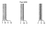
- Fig. 2 shows various variants of how the inner polymer layer 9 can be constructed relative to the anchoring layer 7.
- a barrier layer 11 of PA may be enclosed by two layers 13 made of PE, PP or PU, one of the layers 13 being adjacent to the anchoring layer 7.
- the inner polymer layer 9 can also be formed simply from a layer 13 adjoining the anchoring layer 13 and a barrier layer 11 situated completely outside on the visible side.
- the barrier layer 11 may also be adjacent to the anchoring layer 7 and subsequently within the inner polymer layer 9 a layer 13 located on the outside of the visible side may be provided.
- the impregnated inversible fiber hose (liner) according to the invention
- a 1 m wide and 20 m long web made of a 5 mm thick fiberglass fabric was provided on one side with a 300 ⁇ m thick film of polypropylene, which was later bonded.
- a welded to the tube with a longitudinal seam combination of a 100 micron thick layer of polypropylene nonwoven on a 300 micron film was laminated, consisting of three layers of polyethylene, polyamide and polyethylene of 100 .mu.m thickness were applied.
- the two longitudinal edges of the fiberglass scrim were connected by sewing, so that a 20 m long fiber tube according to the invention was produced.
- the resin contained the usual additives such as wetting additives, deaerating additives and isocyanates for thickening.
Description
Die Erfindung betrifft einen imprägnierten Faserschlauch zur Innenauskleidung von Kanälen und Rohrleitungen, ein Verfahren zur Herstellung des Faserschlauchs, ein Verfahren zur Sanierung von Rohren sowie die Verwendung des Faserschlauchs zur Sanierung von Rohren.The invention relates to an impregnated fiber tube for inner lining of channels and pipelines, a method for producing the fiber tube, a method for rehabilitation of pipes and the use of the fiber tube for the rehabilitation of pipes.
Bislang wurden Rohre so saniert, dass sich in einem harzgetränkten -Glasfaserschlauch (Liner) eine polymere Schlauchinnenfolie befand, welche mittels Druckluft aufgestellt wurde, um den harzgetränkten Faserschlauch gegen die Rohrwand zu drücken. Anschließend wurde im Stand der Technik das Harz entweder durch UV-Bestrahlung oder durch Wärmeeinwirkung (Dampf, Warmwasser oder IR) ausgehärtet.So far, pipes have been redeveloped so that in a resin-impregnated -Glasfaserschlauch (liner) was a polymeric inner tube film, which was placed by means of compressed air to press the resin-impregnated fiber hose against the pipe wall. Subsequently, in the prior art, the resin was cured either by UV irradiation or by heat (steam, hot water or IR).
Bei der UV-Aushärtung wird in der Regel eine Vorrichtung durch den mit Druckluft aufgestellten Schlauch gezogen. Entweder hierbei oder schon zuvor beim Aufbinden der Packer kann es leicht zu Beschädigungen der polymeren Schlauchinnenfolie kommen. Ein Produktionsfehler bei der Herstellung der Schlauchinnenfolie kann ebenfalls nicht ausgeschlossen werden. Schon bei leichten Beschädigungen dringt Druckluft durch die Folie in den nur teilweise ausgehärteten Liner, wodurch zwangsläufig nach Abschluß der Aushärtung ein undichtes Endprodukt entsteht. Bei größeren Beschädigungen (z.B. Folienplatzern) fällt das ganze Produkt in sich zusammen und eine Aushärtung ist unmöglich. Diese Folienprobleme führen dazu, dass der ausgehärtete undichte Liner mühsam herausgefräst werden muss oder bei einem Folienplatzer der zusammengefallene Liner aus der Haltung gezogen und entsorgt werden muss. Beide Fälle führen zu einem erheblichen wirtschaftlichen Schaden.In the case of UV curing, a device is usually drawn through the hose set up with compressed air. Either here or already before when unpacking the packer, it can easily damage the polymeric inner tube film come. A production error in the production of the inner tube film can also not be excluded. Even with slight damage compressed air penetrates through the film in the only partially cured liner, which inevitably results in a leaking final product after completion of curing. In case of major damage (eg foil bursting), the whole product collapses and curing is impossible. These film problems mean that the hardened leaky liner has to be laboriously milled out, or when the film has burst, the collapsed liner has to be pulled out of its position and disposed of. Both cases lead to considerable economic damage.
Im Stand der Technik ist es bisher nicht gelungen, die Schlauchinnenfolie so auszugestalten, dass sie weniger leicht verletzt werden kann und nach der Installation in dem Liner verbleiben könnte, was eine Optimierung des Prozesses auf der Baustelle darstellen würde, weil die Entnahme und Entsorgung der Schlauchinnenfolie entfallen würde.In the prior art, it has not been possible to design the inner tube film so that it could be less easily injured and remain in the liner after installation, which would be an optimization of the process on the site, because the removal and disposal of the inner tube film would be omitted.
Die Aufgabe der vorliegenden Erfindung besteht also darin, einen Faserschlauch zur Innenauskleidung von Kanälen und Rohrleitungen bereitzustellen, bei dem beim Aushärten Verletzungen der Schlauchinnenfolie besser vermieden werden können und die Folie nach der Aushärtung in dem Liner verbleiben kann, was eine Optimierung des Prozesses auf der Baustelle darstellen würde.The object of the present invention is therefore to provide a fiber tube for the inner lining of channels and pipelines, in which during curing, injuries of the tubular inner film can be better avoided and the film can remain in the liner after curing, which would represent an optimization of the process on the construction site.
Die der Erfindung zu Grunde liegende Aufgabe wird in einer ersten Ausführungsform gelöst durch einen imprägnierten Faserschlauch zur Innenauskleidung von Kanälen und Rohrleitungen, der folgendes aufweist:
- a. eine Außenschicht,
- b. eine harzgetränkte Faserschlauchschicht,
- c. eine Verankerungsschicht, und
- d. eine innenliegende Polymerschicht mit mindestens einer Barrierelage,
- a. an outer layer,
- b. a resin-impregnated fiber hose layer,
- c. an anchoring layer, and
- d. an internal polymer layer with at least one barrier layer,
Im Stand der Technik wird beispielsweise in
Ein Dokument
Bislang wurde eine Längsnaht bei der innenliegenden Polymerschicht oder Folie als nachteilig angesehen. Diese Längsnaht wurde bislang mit einer vorprogrammierten Schwachstelle im fertigen Produkt assoziiert. Die Erfinder haben jedoch in der vorliegenden Erfindung herausgefunden, dass die Verwendung von mindestens einer Längsnaht der innenliegenden Polymerschicht den Vorteil hat, dass dadurch eine flächige Polymerschicht mit beispielsweise einer Verankerungsschicht wie beispielsweise einem Vlies vorzugsweise verbunden und insbesondere vollflächig sehr zuverlässig aufkaschiert werden kann oder mit dem Vlies beispielsweise vollflächig zuverlässig verklebt werden kann. Anschließend kann die flächige Polymerschicht mit mindestens einer Längsnaht zu einem Schlauch umgeformt werden. Dies war mit den Folienschläuchen aus dem Stand der Technik bislang nicht möglich. Im Stand der Technik konnten Fehler bei der Kaschierung des Vlieses auf die Folie nicht verhindert werden.So far, a longitudinal seam in the inner polymer layer or film was considered disadvantageous. This longitudinal seam was previously associated with a preprogrammed vulnerability in the finished product. However, the inventors have found in the present invention that the use of at least one longitudinal seam of the inner polymer layer has the advantage that thereby a sheet-like polymer layer with, for example, an anchoring layer such as a Nonwoven preferably connected and in particular over the entire surface can be laminated very reliable or can be glued to the nonwoven, for example, the entire surface reliably. Subsequently, the planar polymer layer can be formed with at least one longitudinal seam to form a tube. This was previously not possible with the film hoses of the prior art. Errors in the lamination of the fleece to the film could not be prevented in the prior art.
Die Längsnaht der innenliegenden Polymerschicht kann beispielsweise durch eine Stoßfuge oder durch Überlappen gebildet sein. Die Längsnaht der innenliegenden Polymerschicht kann beispielsweise eine Schweißnaht sein. Die Längsnaht verläuft vorteilhafterweise in Schlauchrichtung.The longitudinal seam of the inner polymer layer can be formed for example by a butt joint or by overlapping. The longitudinal seam of the inner polymer layer may be, for example, a weld. The longitudinal seam advantageously runs in the tube direction.
Vorzugsweise sind zumindest die Verankerungsschicht c. und die innenliegende Polymerschicht d. stoffschlüssig oder kraftschlüssig miteinander verbunden.Preferably, at least the anchoring layer c. and the inner polymer layer d. cohesive or non-positively connected.
Dadurch dass zumindest die Schichten c. und d. vorzugsweise miteinander stoffschlüssig oder kraftschlüssig verbunden sind, können diese Schichten sich im Unterschied zum Stand der Technik nicht relativ zueinander bewegen. Dadurch wird die Stabilität des gesamten Schichtaufbaus erheblich verbessert. Weiterhin erfährt die innenliegende Polymerschicht durch die damit verbundene Verankerungsschicht eine erhebliche Verstärkung, so dass die innenliegende Polymerschicht nicht mehr leicht verletzt werden kann.Because at least the layers c. and d. are preferably connected to each other cohesively or non-positively, these layers can not move relative to each other in contrast to the prior art. This considerably improves the stability of the entire layer structure. Furthermore, the internal polymer layer undergoes considerable reinforcement due to the anchoring layer connected therewith, so that the inner polymer layer can no longer be easily injured.
Der erfindungsgemäße imprägnierte Faserschlauch ist vorzugsweise inversierfähig. Die bislang bekannten Faserschläuche wie beispielsweise aus
Im Zusammenhang mit dem Inversionsverfahren wird darauf hingewiesen, dass sich der Aufbau des Liners vor der Installation für das Inversionsverfahren und für das Einzugsverfahren selbstverständlich unterscheidet. Die Abfolge der Schichten a. bis d. ist bei einem Liner für das Einzugsverfahren genauso wie die Schichten nach der Installation im Rohr angeordnet. Die Reihenfolge der Schichten vor der Installation bei einem Inversionsliner ist selbstverständlich genau umgekehrt (somit d. bis a.) zu der Schichtfolge nach der Installation. Da es sich um denselben Liner handelt, sind beide Varianten von dieser Erfindung umfasst. Es wird im Rahmen dieses Schutzrechtes die Nomenklatur a. bis d. verwendet, wobei sich versteht, dass der umgestülpte Liner (Abfolge d. bis a.) ebenfalls von der Erfindung umfasst ist.In connection with the inversion process, it should be noted that the structure of the liner before installation for the inversion process and for the collection process of course differs. The sequence of layers a. to d. is located in a liner for the collection process as well as the layers after installation in the pipe. Of course, the order of the layers prior to installation with an inversion liner is the exact opposite (hence d to a) to the post-installation layer sequence. Since this is the same liner, both variants are encompassed by this invention. Within the scope of this property right, the nomenclature a. to d. it being understood that the everted liner (sequence d to a) is also encompassed by the invention.
Die einzelnen Schichten können eine oder auch mehrere Lagen beziehungsweise Materialbahnen umfassen. Diese Lagen beziehungsweise Materialbahnen sind beispielsweise vollflächig miteinander verbunden.The individual layers may comprise one or more layers or material webs. These layers or material webs, for example, are connected to each other over the entire surface.
Die Außenschicht a. weist vorzugsweise eine Dicke in einem Bereich von 40 bis 2000 µm auf. Die Außenschicht ist vorteilhafterweise nicht für UV Strahlung durchlässig, damit das Harz in der harzgetränkten Faserschlauchschicht nicht beispielsweise bei der Lagerung oder beim Transport aushärtet. Die Außenschicht kann beispielsweise aus Polymer oder auch aus einem Vlies mit aufkaschiertem Polymer bestehen. Als Material für Polymer oder Vlies kommen beispielsweise Polyethylen oder Polypropylen in Frage.The outer layer a. preferably has a thickness in a range of 40 to 2000 microns. The outer layer is advantageously not permeable to UV radiation, so that the resin does not harden in the resin-impregnated fiber hose layer, for example during storage or during transport. The outer layer may consist for example of polymer or of a nonwoven with laminated polymer. As a material for polymer or nonwoven, for example, polyethylene or polypropylene come into question.
Die harzgetränkte Faserschlauchschicht b. kann eine Dicke in einem Bereich von 2 bis 30 mm haben. Die Faserschlauchschicht ist vorzugsweise ein Gelege, ein Gewebe, eine Matte, ein Gestrick, ein Vlies, ein Filz, ein Gewirke oder eine Kombination oder ein mehrlagiger Aufbau dieser textilen Flächengebilde. Das Material der Fasern der harzgetränkten Faserschlauchschicht ist vorzugsweise ausgewählt aus Glas, Carbon, Aramid, gelgesponnenem Polyethylen (beispielsweise Dyneema ®), PAN, thermoplastischem Polymer oder Mischungen derselben. Thermoplastische Fasern können beispielsweise aus Polypropylen, Polyethylen oder Polyester sein. Das Material für das Harz kann ausgewählt sein aus der Gruppe ungesättigter Polyesterharze, Vinylesterharze, Epoxidharze, oder Mischungen derselben.The resin impregnated fiber hose layer b. may have a thickness in a range of 2 to 30 mm. The fiber hose layer is preferably a scrim, a woven fabric, a mat, a knitted fabric, a nonwoven fabric, a felt, a knitted fabric or a combination or a multilayer construction of these textile fabrics. The material of the fibers of the resin-impregnated fiber hose layer is preferably selected from glass, carbon, aramid, gel-spun polyethylene (for example Dyneema®), PAN, thermoplastic Polymer or mixtures thereof. Thermoplastic fibers may be, for example, polypropylene, polyethylene or polyester. The material for the resin may be selected from the group of unsaturated polyester resins, vinyl ester resins, epoxy resins, or mixtures thereof.
Die Verankerungsschicht c., die vorzugsweise aus einem thermoplastischen Material besteht, weist Wiederum vorzugsweise eine Dicke in einem Bereich von 10 bis 5000 µm, erfindungsgemäß 30 bis 500 µm auf. Die Verankerungsschicht besteht vorteilhafterweise aus einem Vlies oder einem Schmelzklebstoff oder einer Kombination dieser Varianten. Ganz besonders bevorzugt besteht das Vlies aus Glas, thermoplastischen Materialien, PAN, oder Mischungen derselben. Die thermoplastischen Materialien sind beispielsweise ausgewählt aus Polyethylen, Polypropylen oder Polyester. Der Schmelzklebstoff ist beispielsweise Polyamid, Polyethylen, APAO (amorphes Polyolefin), EVAC (Ethylenvinylacetat-Copolymer), TPE-E (Polyester-Elastomer), TPE-U (Polyurethan-Elastomer), TPE-A (Copolyamid-Elastomer) oder Vinylpyrrolidon/Vinylacetat-Copolymer, sowie Mischungen derselben.The anchoring layer c., Which preferably consists of a thermoplastic material, again preferably has a thickness in a range from 10 to 5000 .mu.m, according to the invention 30 to 500 .mu.m. The anchoring layer is advantageously made of a non-woven or a hot melt adhesive or a combination of these variants. Most preferably, the nonwoven fabric consists of glass, thermoplastic materials, PAN, or mixtures thereof. The thermoplastic materials are for example selected from polyethylene, polypropylene or polyester. The hotmelt adhesive is, for example, polyamide, polyethylene, APAO (amorphous polyolefin), EVAC (ethylene-vinyl acetate copolymer), TPE-E (polyester elastomer), TPE-U (polyurethane elastomer), TPE-A (copolyamide elastomer) or vinylpyrrolidone / Vinyl acetate copolymer, and mixtures thereof.
Die innenliegende Polymerschicht d. weist vorteilhafterweise eine Dicke in einem Bereich von 100 bis 1500 µm auf. Insbesondere weist die innenliegende Polymerschicht eine Dicke in einem Bereich von 100 bis 600 µm auf. Dadurch kann diese innenliegende Polymerschicht zum einen vor mechanischen Verletzungen beispielsweise durch das Gerät zur Aushärtung der harzgetränkten Faserschlauchschicht geschützt werden, ist aber andererseits noch dünn genug, um genügend Wärme oder UV-Strahlung für die Aushärtung durchzulassen. Diese innenliegende Polymerschicht weist vorteilhafterweise mehrere Lagen auf. Eine dieser Lagen ist eine Barrierelage. Diese Barrierelage soll die Diffusion von Reaktivverdünnern wie beispielsweise Styrol von unausgehärtetem Harz verhindern. Diese Barrierelage ist vorteilhafterweise eine der Lagen der Polymerschicht, die nicht außen ("außen" meint hier "für den Betrachter sichtbar" und/oder "an die Verankerungsschicht angrenzend") liegt. Die Barrierelage enthält beispielsweise zu wenigstens 50 Gew.% und besteht insbesondere bevorzugt aus Polyamid, Ethylen-Vinylalkohol-Copolymer, PBT, PET, halogenierten Polymeren oder Mischungen derselben. Besonders bevorzugt besteht die Barrierelage aus einem oder mehreren dieser Materialien. Die Barrierelage weist vorteilhafterweise eine Dicke in einem Bereich von 10 bis 500 µm auf.The inner polymer layer d. advantageously has a thickness in a range of 100 to 1500 microns. In particular, the internal polymer layer has a thickness in a range of 100 to 600 μm. As a result, on the one hand, this inner polymer layer can be protected against mechanical injuries, for example, by the device for curing the resin-impregnated fiber hose layer, but on the other hand, it is still thin enough to allow enough heat or UV radiation to pass through it. This inner polymer layer advantageously has several layers. One of these locations is a barrier location. This barrier layer is intended to prevent the diffusion of reactive diluents such as styrene from uncured resin. This barrier layer is advantageously one of the layers of the polymer layer which does not lie outside ("outside" here means "visible to the viewer" and / or "adjacent to the anchoring layer"). For example, the barrier layer contains at least 50% by weight, and more preferably consists of polyamide, ethylene-vinyl alcohol copolymer, PBT, PET, halogenated polymers or mixtures thereof. Particularly preferably, the barrier layer consists of one or more of these materials. The barrier layer advantageously has a thickness in a range of 10 to 500 μm.
Die Vorteile der erfindungsgemäßen Barrierelage zeigt sich bei dem Vergleich mit dem Stand der Technik, insbesondere bei dem Vergleich mit Filzlinern, die im Inneren eine fest haftende Schicht aus PE, PP oder PUR aufweisen, welche gegenüber Reaktivverdünnern wie z.B. Styrol keine oder ein ungenügende Sperrwirkung zeigt, da Styrol durch die Beschichtung diffundiert und sich an der Oberfläche anreichert. Dies hat zwei Konsequenzen:
- 1.) Bei der Härtung mit Warmwasser oder Dampf findet man signifikante Mengen Styrol im Prozesswasser, welches mit erheblichem Aufwand behandelt oder gesondert entsorgt werden muß, um Umweltschäden zu vermeiden.
- 2.) Bei der Härtung mit UV-Licht ergeben sich gravierende Sicherheitsprobleme, da die untere Explosionsgrenze von Styrol mit Luft binnen weniger Stunden überschritten wird.
- 1.) When curing with hot water or steam can be found significant amounts of styrene in the process water, which must be treated with considerable effort or disposed of separately to avoid environmental damage.
- 2.) Hardening with UV light results in serious safety problems since the lower explosive limit of styrene with air is exceeded within a few hours.
Mit der neuen erfindungsgemäßen Barrierelage in der innen liegenden Polymerschicht, die vorzugsweise stoff- oder kraftschlüssig mit dem Liner verbunden ist, ist es erstmalig möglich, mit einem Liner basierten Sanierungsverfahren Rohre umweltfreundlich zu sanieren. Zudem ist es erstmalig möglich, UV-härtbare Harze und Radikalgeneratoren zu verwenden.With the novel barrier layer according to the invention in the inner polymer layer, which is preferably bonded to the liner in a material or non-positive manner, it is possible for the first time to rehabilitate pipes in an environmentally friendly manner using a liner-based remediation method. In addition, it is possible for the first time to use UV-curable resins and radical generators.
In einer alternativen Ausführungsform kann die Polymerschicht auch aus einer Barrierelage bestehen.In an alternative embodiment, the polymer layer can also consist of a barrier layer.
Die innenliegende Polymerschicht weist vorteilhafterweise wenigstens eine und vorteilhafterweise zwei außenliegende Lagen ("außen" meint hier "für den Betrachter sichtbar" und/oder "an die Verankerungsschicht angrenzend") aus Polyurethan, Polyethylen oder Polypropylen auf. Diese außen liegende Lage weist vorteilhafterweise eine Dicke in einem Bereich von 50 bis 1000 µm auf. Beispielsweise kann die an die Verankerungsschicht angrenzende außen liegende Lage (beispielsweise als Haftlage) dünner sein als die andere außen liegende Lage, die der Schlauchmitte zugewandt ist (nämlich beispielsweise einer Verschleißlage). Dadurch kann die innenliegende Polymerschicht noch besser vor mechanischen Einflüssen schützen.The inner polymer layer advantageously has at least one and advantageously two outer layers ("outside" here means "visible to the viewer" and / or "adjacent to the anchoring layer") made of polyurethane, polyethylene or polypropylene. This outer layer advantageously has a thickness in a range of 50 to 1000 microns. For example, the outer layer adjoining the anchoring layer (for example as an adhesive layer) may be thinner than the other outer layer facing the middle of the hose (namely, for example, a wear layer). As a result, the inner polymer layer can better protect against mechanical influences.
Zwischen der innenliegenden Polymerschicht d. und der Verankerungsschicht c. kann beispielsweise noch eine Schicht aus thermoplastischem Polymer wie Polypropylen oder Polyethylen vorgesehen sein. Diese kann beispielsweise extrudiert werden. Vorzugsweise liegt das Molekulargewicht des Materials dieser Schicht unterhalb des Molekulargewichts des Materials der angrenzenden Lage der innenliegenden Polymerschicht, um ein hohes Maß an Fließfähigkeit und damit an Kraftschlüssigkeit zu ermöglichen.Between the inner polymer layer d. and the anchoring layer c. For example, a layer of thermoplastic polymer such as polypropylene or polyethylene may be provided. This can be extruded, for example. Preferably, the molecular weight of the material of this layer is below the molecular weight of the material of the adjacent layer of the inner polymer layer in order to allow a high degree of fluidity and thus adhesion.
Stoffschlüssig oder kraftschlüssig im Sinne der Erfindung kann vorteilhafterweise bedeuten, dass die jeweiligen Schichten miteinander entweder vollflächig oder teilweise kaschiert, laminiert oder verklebt sind. Falls die Schichten teilweise miteinander verbunden sind, so sind vorzugsweise zumindest 40 % der Fläche der Schichten miteinander verbunden oder alternativ punktuell verbunden. Im Unterschied zum Stand der Technik kann so ein Verrutschen der Schichten gegeneinander vollständig vermieden werden. Die Schichten können zusätzlich oder alternativ auch so verbunden werden, dass ein hochfließfähiges thermoplastisches Material bei der Herstellung zwischen die Schichten extrudiert wird.Cohesive or non-positive in the sense of the invention may advantageously mean that the respective layers are either fully or partially laminated, laminated or glued together. If the layers are partially connected to one another, then preferably at least 40% of the surface of the layers are connected to one another or alternatively selectively connected. In contrast to the prior art, slippage of the layers relative to one another can thus be completely avoided. The layers may additionally or alternatively also be bonded in such a way that a highly flowable thermoplastic material is extruded between the layers during production.
Wenigstens die harzgetränkte Faserschlauchschicht ist vorteilhafterweise nicht gewickelt oder übereinandergeschlagen. Vorzugsweise ist keine der Schichten gewickelt oder übereinandergeschlagen. Vielmehr weist wenigstens die harzgetränkte Faserschlauchschicht vorteilhafterweise mindestens eine Längsnaht auf. Wenigstens diese Schicht ist vorteilhafterweise der Länge nach verschweißt, vernäht, gestrickt oder verklebt. Dies hat den besonderen Vorteil, dass ein imprägnierter Faserschlauch mit einer solchen Faserschlauchschicht in Längsrichtung kaum mehr dehnbar ist und sich somit besonders gut für das Inversionsverfahren eignet. Hingegen weist eine gewickelte harzgetränkte Fasermatte den erheblichen Nachteil auf, dass diese beim Einstülpen des Schlauches in ein Rohr bei einem Inversionsverfahren Gefahr läuft, dass die Wickellagen sich verschieben oder einfach auseinander fallen. Wenigstens diese Schicht ist vorteilhafterweise einstückig.At least the resin impregnated fiber hose layer is advantageously not wound or stacked. Preferably, none of the layers is wound or stacked. Rather, at least the resin-impregnated fiber hose layer advantageously has at least one longitudinal seam. At least this layer is advantageously welded lengthwise, sewn, knitted or glued. This has the particular advantage that an impregnated fiber hose with such a fiber hose layer in the longitudinal direction is hardly stretchable and thus particularly well suited for the inversion process. On the other hand, a wound resin-impregnated fiber mat has the considerable disadvantage that, when the tube is inverted into a tube during an inversion process, it runs the risk of the winding layers shifting or simply falling apart. At least this layer is advantageously in one piece.
In der harzgetränkten Faserschlauchschicht ist das Harz vorzugsweise nicht oder nur teilweise durchpolymerisiert. In der Zusammensetzung des Harzes sind vorteilhafterweise 0,1 bis 20 Gewichtsanteile eines Eindickmittels und insbesondere eines Isocyanats bezogen auf 100 Gewichtsanteile Harz enthalten. Es hat sich herausgestellt, dass hierdurch in der Anwendung bei der Sanierung von Rohren die Zusammensetzung des Harzes hinreichend eingedickt ist, aber bei der Herstellung flüssig genug ist, um die Verankerungsschicht und die Faserschlauchschicht vollständig zu tränken.In the resin-impregnated fiber hose layer, the resin is preferably not or only partially polymerized through. In the composition of the resin are advantageously contained 0.1 to 20 parts by weight of a thickener and in particular an isocyanate based on 100 parts by weight of resin. As a result, it has been found that when used in the rehabilitation of pipes, the composition of the resin is sufficiently thickened, but is liquid enough in the production to completely impregnate the anchoring layer and the fiber hose layer.
Vorzugsweise befindet sich ganz innen zur Rohrmitte hin eine Schicht aus Polyethylen, Polypropylen oder Polyurethan als außen liegende Lage der innen liegenden Polymerschicht. Daran anschließend befindet sich vorteilhafterweise eine Barrierelage als Lage der innen liegenden Polymerschicht. Vorteilhafterweise kann zwischen der Verankerungsschicht c. und der Barrierelage eine Schicht aus Polyethylen oder Polypropylen als weitere Lage der innen liegenden Polymerschicht vorgesehen sein.Preferably, a layer of polyethylene, polypropylene or polyurethane as the outer layer of the inner polymer layer is located completely inside the center of the tube. Subsequently, there is advantageously a barrier layer as the layer of the inner polymer layer. Advantageously, between the anchoring layer c. and the barrier layer a layer of polyethylene or polypropylene may be provided as a further layer of the inner polymer layer.
In einer weiteren Ausführungsform wird die der Erfindung zu Grunde liegende Aufgabe gelöst durch ein Verfahren zur Herstellung des erfindungsgemäßen Faserschlauchs, dadurch gekennzeichnet, dass
- a) eine Materialbahn der Verankerungsschicht und eine Materialbahn der im Endprodukt innenliegenden Polymerschicht stoffschlüssig oder kraftschlüssig miteinander verbunden wird, und
- b) eine Materialbahn der Außenschicht so angeordnet wird, dass sie im Endprodukt ganz außen angeordnet ist, und
- c) wenigstens eine der Materialbahnen der Länge nach an den Außenkanten mit oder ohne Überlappung mit mindestens einer Längsnaht verbunden wird.
- a) a material web of the anchoring layer and a material web of the end product in the inner polymer layer is firmly bonded or non-positively connected, and
- b) a material web of the outer layer is arranged so that it is located in the end product completely outside, and
- c) at least one of the material webs is connected lengthwise at the outer edges with or without overlap with at least one longitudinal seam.
Vorteilhafterweise werden wenigstens zwei, insbesondere wenigstens drei der Materialbahnen in Schritt c) verbunden. Darunter können beispielsweise zwei Lagen der Faserschlauchschicht sein. Dadurch kann der entstehende Faserschlauch deutlich stabilisiert werden und ist wesentlich besser für ein Inversionsverfahren geeignet. Beispielsweise setzt man bei dem erfindungsgemäßen Verfahren für das Material der einen oder mehreren Lagen der Faserschlauchschicht Glasfasermatten ein.Advantageously, at least two, in particular at least three, of the material webs are connected in step c). These may include, for example, two layers of the fiber hose layer. As a result, the resulting fiber tube can be stabilized significantly and is much better suited for an inversion process. For example, in the method according to the invention, glass fiber mats are used for the material of the one or more layers of the fiber hose layer.
Zur besseren Verbindung der einzelnen Schichten oder beispielsweise der besseren Verbindung des Glases mit dem Harz können übliche Haftvermittler wie Silane oder das Coronaverfahren eingesetzt werden.For better bonding of the individual layers or, for example, the better bonding of the glass to the resin, it is possible to use customary adhesion promoters such as silanes or the corona process.
In einer weiteren Ausführungsform wird die der Erfindung zu Grunde liegende Aufgabe gelöst durch ein Verfahren zur Sanierung von Rohren, bei dem ein erfindungsgemäßer Faserschlauch in ein zu sanierendes Rohr eingezogen wird, mit Druckluft an die Rohrinnenwand gedrückt wird, wobei anschließend das Harz der harzgetränkten Faserschlauchschicht ausgehärtet wird.In a further embodiment, the object underlying the invention is achieved by a method for rehabilitation of pipes, in which a fiber tube according to the invention is drawn into a pipe to be rehabilitated, is pressed with compressed air to the pipe inner wall, wherein subsequently cured, the resin of the resin-impregnated fiber hose layer becomes.
In einer weiteren Ausführungsform wird die der Erfindung zu Grunde liegende Aufgabe gelöst durch die Verwendung des erfindungsgemäßen Faserschlauchs zur Sanierung von Rohren oder Kanälen.In a further embodiment, the object underlying the invention is achieved by the use of the fiber tube according to the invention for the rehabilitation of pipes or channels.
In einer weiteren Ausführungsform wird die der Erfindung zu Grunde liegende Aufgabe gelöst durch ein saniertes Rohr, das auf der Rohrinnenseite einen ausgehärteten erfindungsgemäßen Faserschlauch aufweist.In a further embodiment, the object underlying the invention is achieved by a rehabilitated tube having a cured fiber tube according to the invention on the inside of the tube.
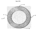
- a.
eine Außenschicht 3, - b. eine harzgetränkte Faserschlauchschicht 5,
c. eine Verankerungsschicht 7 und- d. eine innenliegende Polymerschicht 9,
- a. an
outer layer 3, - b. a resin impregnated fiber tube layer 5,
- c. an
anchoring layer 7 and - d. an internal polymer layer 9,
Für die Herstellung des erfindungsgemäßen imprägnierten inversierfähigen Faserschlauchs (Liner) wurde eine 1 m breite und 20 m lange Bahn aus einem 5 mm dicken Glasfasergelege auf der einen Seite mit einer 300 µm dicken Folie aus Polypropylen durch Auflegen versehen, welche später verklebt wurden. Auf der anderen Seite wurde eine zum Schlauch mit einer Längsnaht geschweißte Kombination aus einer 100 µm dicken Schicht aus Polypropylenvlies auf der eine 300 µm Folie aufkaschiert war, die aus drei gleichdicken Lagen Polyethylen, Polyamid und Polyethylen zu jeweils 100 µm bestand, aufgelegt. Anschließend wurden die beiden Längskanten der Glasfasergelege durch Vernähen verbunden, so dass ein 20 m langer erfindungsgemäßer Faserschlauch entstand. Dieser wurde anschließend mit einem marktüblichen UV-initiierten UP-Harz für das Relining unter Vakuum imprägniert. Das Harz enthielt die üblichen Zusatzstoffe wie u.a. Benetzungsadditive, Entlüftungsadditive und Isocyanate zum Eindicken.For the production of the impregnated inversible fiber hose (liner) according to the invention, a 1 m wide and 20 m long web made of a 5 mm thick fiberglass fabric was provided on one side with a 300 μm thick film of polypropylene, which was later bonded. On the other hand, a welded to the tube with a longitudinal seam combination of a 100 micron thick layer of polypropylene nonwoven on a 300 micron film was laminated, consisting of three layers of polyethylene, polyamide and polyethylene of 100 .mu.m thickness were applied. Subsequently, the two longitudinal edges of the fiberglass scrim were connected by sewing, so that a 20 m long fiber tube according to the invention was produced. This was then impregnated with a commercially available UV-initiated UP resin for relining under vacuum. The resin contained the usual additives such as wetting additives, deaerating additives and isocyanates for thickening.
- 11
- imprägnierter Faserschlauch (Liner)impregnated fiber hose (liner)
- 33
- Außenschicht (a.)Outer layer (a.)
- 55
- harzgetränkte Faserschlauchschicht (b.)Resin-impregnated fiber hose layer (b.)
- 77
- Verankerungsschicht (c.)Anchoring layer (c.)
- 99
- innenliegende Polymerschicht (d.)internal polymer layer (d.)
- 1111
- Barrierelage, Teil der innenliegenden PolymerschichtBarrier layer, part of the inner polymer layer
- 1313
- Lage aus Polymer, Teil der innenliegenden PolymerschichtLayer of polymer, part of the inner polymer layer
Claims (9)
- Impregnated fiber tube for internally lining conduits and pipes, said fiber tube comprising:a. an outer layer,b. a resin-impregnated fiber tube layer,c. an anchoring layer, andd. an inner polymer layer including at least one barrier ply, andwherein the inner polymer layer comprises at least one longitudinal seam,
and wherein the thickness of the anchoring layer is within a range of 30 to 500 µm - Fiber tube according to claim 1, characterized in that at least the anchoring layer and the inner polymer layer are connected with each other by a substance-to-substance connection or non-positively.
- Fiber tube according to one of claims 1 or 2, characterized in that the non-positive or substance-to-substance connection is a layup, lamination or adhesive bond.
- Fiber tube according to one of claims1 to 3, characterized in that the substance-to-substance or non-positive connection is provided over the entire surface.
- Method of manufacturing the fiber tube according to one of claims 1 to 4, characterized in thata) a material sheet of the anchoring layer and a material sheet of the inner polymer layer of the end product are connected with each other by a substance-to-substance connection or non-positively, andb) a material sheet of the outer layer is arranged such that it is located at an outermost position in the end product, andc) at least one of the material sheets is longitudinally connected at the outer edges with or without overlapping by at least one longitudinal seam.
- Method according to claim 5, characterized in that at least two, more preferably at least three of the material sheets are connected with each other in step c).
- Method of rehabilitating pipes, characterized in that a fiber tube according to one of claims 1 to 4 is inserted into a pipe to be rehabilitated, pressed with compressed air against the inner wall of the pipe, wherein the resin of the resin-impregnated fiber tube layer subsequently hardens.
- Use of the fiber tube according to one of claims 1 to 4 for rehabilitating pipes or conduits.
- Rehabilitated pipe which comprises a hardened fiber tube according to one of claims 1 to 4 at the inner surface of the pipe.
Priority Applications (2)
| Application Number | Priority Date | Filing Date | Title |
|---|---|---|---|
| EP11182525.3A EP2573442B1 (en) | 2011-09-23 | 2011-09-23 | Liner with internal coating |
| US13/624,024 US9829142B2 (en) | 2011-09-23 | 2012-09-21 | Internally coated liner |
Applications Claiming Priority (1)
| Application Number | Priority Date | Filing Date | Title |
|---|---|---|---|
| EP11182525.3A EP2573442B1 (en) | 2011-09-23 | 2011-09-23 | Liner with internal coating |
Publications (2)
| Publication Number | Publication Date |
|---|---|
| EP2573442A1 EP2573442A1 (en) | 2013-03-27 |
| EP2573442B1 true EP2573442B1 (en) | 2015-12-30 |
Family
ID=44785483
Family Applications (1)
| Application Number | Title | Priority Date | Filing Date |
|---|---|---|---|
| EP11182525.3A Active EP2573442B1 (en) | 2011-09-23 | 2011-09-23 | Liner with internal coating |
Country Status (2)
| Country | Link |
|---|---|
| US (1) | US9829142B2 (en) |
| EP (1) | EP2573442B1 (en) |
Cited By (1)
| Publication number | Priority date | Publication date | Assignee | Title |
|---|---|---|---|---|
| WO2019072900A1 (en) | 2017-10-10 | 2019-04-18 | Brandenburger Patentverwertung Gbr | Method and arrangement for renovating a line which carries a liquid or gaseous medium |
Families Citing this family (22)
| Publication number | Priority date | Publication date | Assignee | Title |
|---|---|---|---|---|
| JP2014517220A (en) | 2011-04-18 | 2014-07-17 | ファイフ カンパニー,エルエルシー | Protective expansion liner and reinforcement of existing pipes |
| DE202012104166U1 (en) | 2012-10-30 | 2012-11-23 | Trelleborg Pipe Seals Duisburg Gmbh | Lining element for rehabilitation of a pipeline |
| DE102013203840A1 (en) * | 2013-03-06 | 2014-09-11 | Saertex Multicom Gmbh | Short liner for sewer rehabilitation |
| DE102014103243A1 (en) * | 2013-03-11 | 2014-09-11 | Buergofol GmbH | Method for partially coating a tubular film |
| ES2922077T3 (en) | 2013-04-05 | 2022-09-07 | Buergofol GmbH | Method for lamination of a tubular film |
| EP2827040A1 (en) | 2013-07-19 | 2015-01-21 | Per Aarsleff A/S | A reinforced liner for renovation of underground pipe systems, a method of producing a reinforced liner and a method of installing a reinforced liner into a pipe line |
| CN106662284A (en) | 2014-06-16 | 2017-05-10 | 法伊夫有限责任公司 | Repair of pipes |
| WO2016009361A1 (en) | 2014-07-14 | 2016-01-21 | Fyfe Co. Llc | Method of reininforcing a pipe with a pipe lining, reinforced pipe and method of waterproofing a reinforced pipe |
| DE102014110929A1 (en) | 2014-07-31 | 2016-02-04 | Sml Verwaltungs Gmbh | Lining hose for refurbishment of fluid-carrying piping systems |
| DE102014110930A1 (en) | 2014-07-31 | 2016-02-04 | Sml Verwaltungs Gmbh | Lining hose for refurbishment of fluid-carrying piping systems |
| DE102014114746B4 (en) | 2014-10-10 | 2018-06-21 | Saertex Multicom Gmbh | Kanalsanierung Liner |
| DE102014118689A1 (en) | 2014-12-15 | 2016-06-16 | Sml Verwaltungs Gmbh | Lining hose for refurbishment of fluid-carrying systems |
| DE102015105668C5 (en) * | 2015-04-14 | 2020-07-09 | Cuylits Holding GmbH | Composite hose for repairing leaky fluid lines, method for producing such a composite hose and method for repairing leaky fluid lines with a composite hose |
| US9993992B2 (en) | 2015-04-17 | 2018-06-12 | Fyfe Co. Llc | Structural fabric useful for lining pipe |
| US10077855B2 (en) | 2015-09-22 | 2018-09-18 | Ina Acquisition Corp. | Method of lining pipe with high strength liner, high strength liner, and pipe lined with high strength liner |
| DE102015013856A1 (en) | 2015-10-06 | 2017-04-06 | Brandenburger Patentverwertung GbR (vertretungsberechtigter Gesellschafter: Tim Brandenburger, 76829 Landau) | Sewer hose for sewer rehabilitation and method of making such |
| SE543067C2 (en) * | 2015-10-09 | 2020-09-29 | Pressure Pipe Relining Sweden Ab | A method of renovating a district heating pipe, a tubular liner for re-lining and use thereof |
| CN107559501B (en) * | 2017-09-29 | 2019-04-02 | 安徽德全新型建材科技有限公司 | A kind of safe steam conveying pipe |
| US11173634B2 (en) | 2018-02-01 | 2021-11-16 | Ina Acquisition Corp | Electromagnetic radiation curable pipe liner and method of making and installing the same |
| US10704728B2 (en) | 2018-03-20 | 2020-07-07 | Ina Acquisition Corp. | Pipe liner and method of making same |
| DE102018123339A1 (en) * | 2018-09-21 | 2020-03-26 | Saertex Multicom Gmbh | Refurbishment of high temperature pipes |
| DE102020127230A1 (en) | 2020-10-15 | 2022-04-21 | Saertex Multicom Gmbh | Curing of liners using coherent electromagnetic radiation |
Citations (14)
| Publication number | Priority date | Publication date | Assignee | Title |
|---|---|---|---|---|
| WO1991018234A1 (en) | 1990-05-18 | 1991-11-28 | Softlining Ag, Systems For Relining | Ready-for-use, sandwich mending tube for renovating the inside of damaged drain channels and process for producing the same |
| EP0863359A1 (en) | 1997-03-07 | 1998-09-09 | Rothenberger Rohrsanierung GmbH | Method and apparatus for manufacturing a hose for lining of pipelines and channel systems |
| DE19924251A1 (en) | 1999-05-27 | 2000-11-30 | Joachim Brandenburger | Lining tube with non-woven layer laminated on foil tube |
| DE69131474T3 (en) | 1990-04-10 | 2004-03-04 | Ashimori Industry Co. Ltd. | Pipe coating material and method |
| US20050028880A1 (en) * | 2002-03-14 | 2005-02-10 | Smith E. Peter | Fiber reinforced composite liner for lining an existing conduit and method of manufacture |
| WO2010033297A2 (en) | 2008-09-19 | 2010-03-25 | Lightstream, L.P. | Cured-in-place liner material and methods and systems for manufacture |
| DE102009041841A1 (en) * | 2008-12-17 | 2010-07-08 | Huhtamaki Forchheim Zweigniederlassung Der Huhtamaki Deutschland Gmbh & Co. Kg | UV and light protection film |
| WO2010111025A1 (en) | 2009-03-24 | 2010-09-30 | Lubrizol Advanced Materials, Inc. | Cured in place pipe liner with styrene barrier |
| US20100243091A1 (en) | 2009-03-27 | 2010-09-30 | Perma-Liner Industries, Inc. | Scrim-Enforced Pipe Liner |
| EP2253456A1 (en) | 2009-05-22 | 2010-11-24 | Nicod Industrie Design UG | Cladding hose for renovating conduit systems for transporting liquid |
| WO2011006618A1 (en) | 2009-07-13 | 2011-01-20 | Sml Verwaltungs-Gmbh | Tubular liner for the restoration of fluid-conveying pipe systems, and method for the production thereof |
| DE102009038628A1 (en) | 2009-08-26 | 2011-03-03 | Lantor Gmbh | Composite film for producing hose for inner lining of e.g. sewer pipes, has textile layer formed such that textile layer is connectable with outer side of fabric web of hose, and film part designed as filter against ultraviolet radiation |
| WO2012065698A2 (en) | 2010-11-15 | 2012-05-24 | Brandenburger Patentverwertung Gbr | Lining tube for sewer rehabilitation and method and arrangement for producing such a tube |
| WO2013000556A2 (en) | 2011-06-27 | 2013-01-03 | Sml Verwaltungs Gmbh | Lining tube for refurbishing fluid-conveying systems |
Family Cites Families (7)
| Publication number | Priority date | Publication date | Assignee | Title |
|---|---|---|---|---|
| JPS61143128A (en) * | 1984-12-17 | 1986-06-30 | 芦森工業株式会社 | Inner lining material for duct |
| GB8501474D0 (en) * | 1985-01-21 | 1985-02-20 | Edgealpha Ltd | Lining of passageways |
| US5411060A (en) * | 1992-04-03 | 1995-05-02 | Chandler; Brian | Composite pipe |
| DE19850227C1 (en) * | 1998-10-26 | 2000-06-21 | Siegfried Schwert | Hose for lining pipes |
| WO2003083338A1 (en) * | 2002-03-29 | 2003-10-09 | Fiberspar Corporation | Systems and methods for pipeline rehabilitation |
| US7478650B2 (en) * | 2002-06-19 | 2009-01-20 | Saint-Gobain Technical Fabrics Canada, Ltd. | Inversion liner and liner components for conduits |
| WO2012082949A1 (en) * | 2010-12-14 | 2012-06-21 | Lightstream, Lp | Curable pressure pipe liner |
-
2011
- 2011-09-23 EP EP11182525.3A patent/EP2573442B1/en active Active
-
2012
- 2012-09-21 US US13/624,024 patent/US9829142B2/en active Active
Patent Citations (17)
| Publication number | Priority date | Publication date | Assignee | Title |
|---|---|---|---|---|
| DE69131474T3 (en) | 1990-04-10 | 2004-03-04 | Ashimori Industry Co. Ltd. | Pipe coating material and method |
| WO1991018234A1 (en) | 1990-05-18 | 1991-11-28 | Softlining Ag, Systems For Relining | Ready-for-use, sandwich mending tube for renovating the inside of damaged drain channels and process for producing the same |
| EP0863359A1 (en) | 1997-03-07 | 1998-09-09 | Rothenberger Rohrsanierung GmbH | Method and apparatus for manufacturing a hose for lining of pipelines and channel systems |
| DE19924251A1 (en) | 1999-05-27 | 2000-11-30 | Joachim Brandenburger | Lining tube with non-woven layer laminated on foil tube |
| WO2000073692A1 (en) | 1999-05-27 | 2000-12-07 | Betz, Wilhelm, Leo | Liner with a tubular film that is coated with a nonwoven |
| US20050028880A1 (en) * | 2002-03-14 | 2005-02-10 | Smith E. Peter | Fiber reinforced composite liner for lining an existing conduit and method of manufacture |
| WO2010033297A2 (en) | 2008-09-19 | 2010-03-25 | Lightstream, L.P. | Cured-in-place liner material and methods and systems for manufacture |
| US20100075078A1 (en) | 2008-09-19 | 2010-03-25 | Lightstream, L.P. | Cured-in-place liner material and methods and systems for manufacture |
| DE102009041841A1 (en) * | 2008-12-17 | 2010-07-08 | Huhtamaki Forchheim Zweigniederlassung Der Huhtamaki Deutschland Gmbh & Co. Kg | UV and light protection film |
| WO2010111025A1 (en) | 2009-03-24 | 2010-09-30 | Lubrizol Advanced Materials, Inc. | Cured in place pipe liner with styrene barrier |
| US20100243091A1 (en) | 2009-03-27 | 2010-09-30 | Perma-Liner Industries, Inc. | Scrim-Enforced Pipe Liner |
| EP2253456A1 (en) | 2009-05-22 | 2010-11-24 | Nicod Industrie Design UG | Cladding hose for renovating conduit systems for transporting liquid |
| WO2011006618A1 (en) | 2009-07-13 | 2011-01-20 | Sml Verwaltungs-Gmbh | Tubular liner for the restoration of fluid-conveying pipe systems, and method for the production thereof |
| DE102009038628A1 (en) | 2009-08-26 | 2011-03-03 | Lantor Gmbh | Composite film for producing hose for inner lining of e.g. sewer pipes, has textile layer formed such that textile layer is connectable with outer side of fabric web of hose, and film part designed as filter against ultraviolet radiation |
| WO2012065698A2 (en) | 2010-11-15 | 2012-05-24 | Brandenburger Patentverwertung Gbr | Lining tube for sewer rehabilitation and method and arrangement for producing such a tube |
| EP2641005B1 (en) | 2010-11-15 | 2014-10-08 | Brandenburger Patentverwertung GBR | Liner for sewer rehabilitation and method and arrangement for producing such a liner |
| WO2013000556A2 (en) | 2011-06-27 | 2013-01-03 | Sml Verwaltungs Gmbh | Lining tube for refurbishing fluid-conveying systems |
Cited By (2)
| Publication number | Priority date | Publication date | Assignee | Title |
|---|---|---|---|---|
| WO2019072900A1 (en) | 2017-10-10 | 2019-04-18 | Brandenburger Patentverwertung Gbr | Method and arrangement for renovating a line which carries a liquid or gaseous medium |
| EP3695157B1 (en) | 2017-10-10 | 2021-09-08 | Brandenburger Liner GmbH & Co. KG | Method and arrangement for renovating a line which carries a liquid or gaseous medium |
Also Published As
| Publication number | Publication date |
|---|---|
| US20130074972A1 (en) | 2013-03-28 |
| EP2573442A1 (en) | 2013-03-27 |
| US9829142B2 (en) | 2017-11-28 |
Similar Documents
| Publication | Publication Date | Title |
|---|---|---|
| EP2573442B1 (en) | Liner with internal coating | |
| EP2768655B1 (en) | Lining tube, renovated pressure pipe and method for renovating a pressure pipe | |
| EP2491291B1 (en) | Multilayer tube having a tubular inner film, method for producing same, and use thereof | |
| EP2725277B1 (en) | Internal coating material for pipes and method of retrofitting defective waste water channels | |
| DE102009033140A1 (en) | Lining hose for the rehabilitation of fluid-carrying piping systems and method for its production | |
| DE102016117513A1 (en) | Method of lining a pipe with high strength lining, high strength lining and pipe lined with high strength lining | |
| WO2017059936A1 (en) | Liner tube for sewer rehabilitation and method for producing same | |
| EP2724064A2 (en) | Lining tube for refurbishing fluid-conveying systems | |
| WO2014135602A1 (en) | Short liner for sewer rehabilitation | |
| EP3683053B1 (en) | Method for laminating a tubular film | |
| EP3174703B1 (en) | Tubular liner for the rehabilitation of fluid-conducting pipeline systems | |
| DE4113002A1 (en) | METHOD FOR PRODUCING A LOCKED, LOCKABLE PLASTIC HOSE AND DEVICE THEREFOR | |
| EP3071872B1 (en) | Liner tube for renovating fluid-bearing pipe systems, method and use | |
| DE102013114630A1 (en) | Lining element for rehabilitation of a pipeline | |
| EP3174702A1 (en) | Tubular liner for the rehabilitation of fluid-conducting pipeline systems | |
| DE102013111092A1 (en) | Lining hose for the refurbishment of fluid-carrying piping systems | |
| DE102014112600B3 (en) | Short liner with integrated hat profile, kit for making such a short liner and method for rehabilitating a channel with a branch | |
| EP3023683A1 (en) | Knitted liner having longitudinal elongation brake | |
| WO2016016346A1 (en) | Tubular, photochemically curable liners for rehabilitating fluid-bearing systems | |
| DE202021105464U1 (en) | Textile fabric with high light permeability | |
| DE102014114746B4 (en) | Kanalsanierung Liner | |
| WO2022029276A1 (en) | Lining tube for renovating fluid-conducting pipeline systems and multilayered composite systems | |
| DE102016120225A1 (en) | Sealing system and method for making an insert tube with such a sealing system |
Legal Events
| Date | Code | Title | Description |
|---|---|---|---|
| PUAI | Public reference made under article 153(3) epc to a published international application that has entered the european phase |
Free format text: ORIGINAL CODE: 0009012 |
|
| 17P | Request for examination filed |
Effective date: 20120914 |
|
| AK | Designated contracting states |
Kind code of ref document: A1 Designated state(s): AL AT BE BG CH CY CZ DE DK EE ES FI FR GB GR HR HU IE IS IT LI LT LU LV MC MK MT NL NO PL PT RO RS SE SI SK SM TR |
|
| AX | Request for extension of the european patent |
Extension state: BA ME |
|
| 17Q | First examination report despatched |
Effective date: 20140527 |
|
| GRAP | Despatch of communication of intention to grant a patent |
Free format text: ORIGINAL CODE: EPIDOSNIGR1 |
|
| INTG | Intention to grant announced |
Effective date: 20150410 |
|
| TPAC | Observations filed by third parties |
Free format text: ORIGINAL CODE: EPIDOSNTIPA |
|
| GRAS | Grant fee paid |
Free format text: ORIGINAL CODE: EPIDOSNIGR3 |
|
| GRAA | (expected) grant |
Free format text: ORIGINAL CODE: 0009210 |
|
| STAA | Information on the status of an ep patent application or granted ep patent |
Free format text: STATUS: THE PATENT HAS BEEN GRANTED |
|
| AK | Designated contracting states |
Kind code of ref document: B1 Designated state(s): AL AT BE BG CH CY CZ DE DK EE ES FI FR GB GR HR HU IE IS IT LI LT LU LV MC MK MT NL NO PL PT RO RS SE SI SK SM TR |
|
| REG | Reference to a national code |
Ref country code: GB Ref legal event code: FG4D Free format text: NOT ENGLISH |
|
| REG | Reference to a national code |
Ref country code: CH Ref legal event code: EP |
|
| REG | Reference to a national code |
Ref country code: AT Ref legal event code: REF Ref document number: 767654 Country of ref document: AT Kind code of ref document: T Effective date: 20160115 |
|
| REG | Reference to a national code |
Ref country code: IE Ref legal event code: FG4D Free format text: LANGUAGE OF EP DOCUMENT: GERMAN |
|
| REG | Reference to a national code |
Ref country code: DE Ref legal event code: R096 Ref document number: 502011008554 Country of ref document: DE |
|
| REG | Reference to a national code |
Ref country code: LT Ref legal event code: MG4D |
|
| PG25 | Lapsed in a contracting state [announced via postgrant information from national office to epo] |
Ref country code: LT Free format text: LAPSE BECAUSE OF FAILURE TO SUBMIT A TRANSLATION OF THE DESCRIPTION OR TO PAY THE FEE WITHIN THE PRESCRIBED TIME-LIMIT Effective date: 20151230 Ref country code: HR Free format text: LAPSE BECAUSE OF FAILURE TO SUBMIT A TRANSLATION OF THE DESCRIPTION OR TO PAY THE FEE WITHIN THE PRESCRIBED TIME-LIMIT Effective date: 20151230 Ref country code: NO Free format text: LAPSE BECAUSE OF FAILURE TO SUBMIT A TRANSLATION OF THE DESCRIPTION OR TO PAY THE FEE WITHIN THE PRESCRIBED TIME-LIMIT Effective date: 20160330 |
|
| REG | Reference to a national code |
Ref country code: NL Ref legal event code: MP Effective date: 20151230 |
|
| PG25 | Lapsed in a contracting state [announced via postgrant information from national office to epo] |
Ref country code: FI Free format text: LAPSE BECAUSE OF FAILURE TO SUBMIT A TRANSLATION OF THE DESCRIPTION OR TO PAY THE FEE WITHIN THE PRESCRIBED TIME-LIMIT Effective date: 20151230 Ref country code: LV Free format text: LAPSE BECAUSE OF FAILURE TO SUBMIT A TRANSLATION OF THE DESCRIPTION OR TO PAY THE FEE WITHIN THE PRESCRIBED TIME-LIMIT Effective date: 20151230 Ref country code: RS Free format text: LAPSE BECAUSE OF FAILURE TO SUBMIT A TRANSLATION OF THE DESCRIPTION OR TO PAY THE FEE WITHIN THE PRESCRIBED TIME-LIMIT Effective date: 20151230 Ref country code: SE Free format text: LAPSE BECAUSE OF FAILURE TO SUBMIT A TRANSLATION OF THE DESCRIPTION OR TO PAY THE FEE WITHIN THE PRESCRIBED TIME-LIMIT Effective date: 20151230 Ref country code: GR Free format text: LAPSE BECAUSE OF FAILURE TO SUBMIT A TRANSLATION OF THE DESCRIPTION OR TO PAY THE FEE WITHIN THE PRESCRIBED TIME-LIMIT Effective date: 20160331 |
|
| PG25 | Lapsed in a contracting state [announced via postgrant information from national office to epo] |
Ref country code: NL Free format text: LAPSE BECAUSE OF FAILURE TO SUBMIT A TRANSLATION OF THE DESCRIPTION OR TO PAY THE FEE WITHIN THE PRESCRIBED TIME-LIMIT Effective date: 20151230 |
|
| PG25 | Lapsed in a contracting state [announced via postgrant information from national office to epo] |
Ref country code: ES Free format text: LAPSE BECAUSE OF FAILURE TO SUBMIT A TRANSLATION OF THE DESCRIPTION OR TO PAY THE FEE WITHIN THE PRESCRIBED TIME-LIMIT Effective date: 20151230 Ref country code: IT Free format text: LAPSE BECAUSE OF FAILURE TO SUBMIT A TRANSLATION OF THE DESCRIPTION OR TO PAY THE FEE WITHIN THE PRESCRIBED TIME-LIMIT Effective date: 20151230 Ref country code: CZ Free format text: LAPSE BECAUSE OF FAILURE TO SUBMIT A TRANSLATION OF THE DESCRIPTION OR TO PAY THE FEE WITHIN THE PRESCRIBED TIME-LIMIT Effective date: 20151230 |
|
| PG25 | Lapsed in a contracting state [announced via postgrant information from national office to epo] |
Ref country code: SK Free format text: LAPSE BECAUSE OF FAILURE TO SUBMIT A TRANSLATION OF THE DESCRIPTION OR TO PAY THE FEE WITHIN THE PRESCRIBED TIME-LIMIT Effective date: 20151230 Ref country code: PT Free format text: LAPSE BECAUSE OF FAILURE TO SUBMIT A TRANSLATION OF THE DESCRIPTION OR TO PAY THE FEE WITHIN THE PRESCRIBED TIME-LIMIT Effective date: 20160502 Ref country code: IS Free format text: LAPSE BECAUSE OF FAILURE TO SUBMIT A TRANSLATION OF THE DESCRIPTION OR TO PAY THE FEE WITHIN THE PRESCRIBED TIME-LIMIT Effective date: 20160430 Ref country code: SM Free format text: LAPSE BECAUSE OF FAILURE TO SUBMIT A TRANSLATION OF THE DESCRIPTION OR TO PAY THE FEE WITHIN THE PRESCRIBED TIME-LIMIT Effective date: 20151230 Ref country code: RO Free format text: LAPSE BECAUSE OF FAILURE TO SUBMIT A TRANSLATION OF THE DESCRIPTION OR TO PAY THE FEE WITHIN THE PRESCRIBED TIME-LIMIT Effective date: 20151230 Ref country code: PL Free format text: LAPSE BECAUSE OF FAILURE TO SUBMIT A TRANSLATION OF THE DESCRIPTION OR TO PAY THE FEE WITHIN THE PRESCRIBED TIME-LIMIT Effective date: 20151230 Ref country code: EE Free format text: LAPSE BECAUSE OF FAILURE TO SUBMIT A TRANSLATION OF THE DESCRIPTION OR TO PAY THE FEE WITHIN THE PRESCRIBED TIME-LIMIT Effective date: 20151230 |
|
| REG | Reference to a national code |
Ref country code: DE Ref legal event code: R026 Ref document number: 502011008554 Country of ref document: DE |
|
| REG | Reference to a national code |
Ref country code: FR Ref legal event code: PLFP Year of fee payment: 6 |
|
| PLBI | Opposition filed |
Free format text: ORIGINAL CODE: 0009260 |
|
| PLBI | Opposition filed |
Free format text: ORIGINAL CODE: 0009260 |
|
| PG25 | Lapsed in a contracting state [announced via postgrant information from national office to epo] |
Ref country code: DK Free format text: LAPSE BECAUSE OF FAILURE TO SUBMIT A TRANSLATION OF THE DESCRIPTION OR TO PAY THE FEE WITHIN THE PRESCRIBED TIME-LIMIT Effective date: 20151230 |
|
| 26 | Opposition filed |
Opponent name: IMPREG GMBH Effective date: 20160921 |
|
| PLAX | Notice of opposition and request to file observation + time limit sent |
Free format text: ORIGINAL CODE: EPIDOSNOBS2 |
|
| 26 | Opposition filed |
Opponent name: RELINEEUROPE AG Effective date: 20160929 Opponent name: BRANDENBURGER PATENTVERWERTUNG GBR Effective date: 20161004 |
|
| PG25 | Lapsed in a contracting state [announced via postgrant information from national office to epo] |
Ref country code: BE Free format text: LAPSE BECAUSE OF NON-PAYMENT OF DUE FEES Effective date: 20160930 Ref country code: SI Free format text: LAPSE BECAUSE OF FAILURE TO SUBMIT A TRANSLATION OF THE DESCRIPTION OR TO PAY THE FEE WITHIN THE PRESCRIBED TIME-LIMIT Effective date: 20151230 |
|
| PLBB | Reply of patent proprietor to notice(s) of opposition received |
Free format text: ORIGINAL CODE: EPIDOSNOBS3 |
|
| PG25 | Lapsed in a contracting state [announced via postgrant information from national office to epo] |
Ref country code: MC Free format text: LAPSE BECAUSE OF FAILURE TO SUBMIT A TRANSLATION OF THE DESCRIPTION OR TO PAY THE FEE WITHIN THE PRESCRIBED TIME-LIMIT Effective date: 20151230 |
|
| REG | Reference to a national code |
Ref country code: CH Ref legal event code: PL |
|
| REG | Reference to a national code |
Ref country code: IE Ref legal event code: MM4A |
|
| PLAB | Opposition data, opponent's data or that of the opponent's representative modified |
Free format text: ORIGINAL CODE: 0009299OPPO |
|
| PG25 | Lapsed in a contracting state [announced via postgrant information from national office to epo] |
Ref country code: CH Free format text: LAPSE BECAUSE OF NON-PAYMENT OF DUE FEES Effective date: 20160930 Ref country code: LI Free format text: LAPSE BECAUSE OF NON-PAYMENT OF DUE FEES Effective date: 20160930 Ref country code: IE Free format text: LAPSE BECAUSE OF NON-PAYMENT OF DUE FEES Effective date: 20160923 |
|
| R26 | Opposition filed (corrected) |
Opponent name: IMPREG GMBH Effective date: 20160921 |
|
| PG25 | Lapsed in a contracting state [announced via postgrant information from national office to epo] |
Ref country code: LU Free format text: LAPSE BECAUSE OF NON-PAYMENT OF DUE FEES Effective date: 20160923 |
|
| REG | Reference to a national code |
Ref country code: FR Ref legal event code: PLFP Year of fee payment: 7 |
|
| REG | Reference to a national code |
Ref country code: BE Ref legal event code: MM Effective date: 20160930 |
|
| PG25 | Lapsed in a contracting state [announced via postgrant information from national office to epo] |
Ref country code: HU Free format text: LAPSE BECAUSE OF FAILURE TO SUBMIT A TRANSLATION OF THE DESCRIPTION OR TO PAY THE FEE WITHIN THE PRESCRIBED TIME-LIMIT; INVALID AB INITIO Effective date: 20110923 Ref country code: CY Free format text: LAPSE BECAUSE OF FAILURE TO SUBMIT A TRANSLATION OF THE DESCRIPTION OR TO PAY THE FEE WITHIN THE PRESCRIBED TIME-LIMIT Effective date: 20151230 |
|
| PG25 | Lapsed in a contracting state [announced via postgrant information from national office to epo] |
Ref country code: MK Free format text: LAPSE BECAUSE OF FAILURE TO SUBMIT A TRANSLATION OF THE DESCRIPTION OR TO PAY THE FEE WITHIN THE PRESCRIBED TIME-LIMIT Effective date: 20151230 Ref country code: TR Free format text: LAPSE BECAUSE OF FAILURE TO SUBMIT A TRANSLATION OF THE DESCRIPTION OR TO PAY THE FEE WITHIN THE PRESCRIBED TIME-LIMIT Effective date: 20151230 Ref country code: MT Free format text: LAPSE BECAUSE OF FAILURE TO SUBMIT A TRANSLATION OF THE DESCRIPTION OR TO PAY THE FEE WITHIN THE PRESCRIBED TIME-LIMIT Effective date: 20151230 |
|
| RDAF | Communication despatched that patent is revoked |
Free format text: ORIGINAL CODE: EPIDOSNREV1 |
|
| STAA | Information on the status of an ep patent application or granted ep patent |
Free format text: STATUS: THE PATENT HAS BEEN GRANTED |
|
| PG25 | Lapsed in a contracting state [announced via postgrant information from national office to epo] |
Ref country code: BG Free format text: LAPSE BECAUSE OF FAILURE TO SUBMIT A TRANSLATION OF THE DESCRIPTION OR TO PAY THE FEE WITHIN THE PRESCRIBED TIME-LIMIT Effective date: 20151230 |
|
| APAH | Appeal reference modified |
Free format text: ORIGINAL CODE: EPIDOSCREFNO |
|
| APBM | Appeal reference recorded |
Free format text: ORIGINAL CODE: EPIDOSNREFNO |
|
| APBP | Date of receipt of notice of appeal recorded |
Free format text: ORIGINAL CODE: EPIDOSNNOA2O |
|
| REG | Reference to a national code |
Ref country code: FR Ref legal event code: PLFP Year of fee payment: 8 |
|
| PG25 | Lapsed in a contracting state [announced via postgrant information from national office to epo] |
Ref country code: AL Free format text: LAPSE BECAUSE OF FAILURE TO SUBMIT A TRANSLATION OF THE DESCRIPTION OR TO PAY THE FEE WITHIN THE PRESCRIBED TIME-LIMIT Effective date: 20151230 |
|
| APBQ | Date of receipt of statement of grounds of appeal recorded |
Free format text: ORIGINAL CODE: EPIDOSNNOA3O |
|
| REG | Reference to a national code |
Ref country code: DE Ref legal event code: R082 Ref document number: 502011008554 Country of ref document: DE Representative=s name: MICHALSKI HUETTERMANN & PARTNER PATENTANWAELTE, DE |
|
| PGFP | Annual fee paid to national office [announced via postgrant information from national office to epo] |
Ref country code: GB Payment date: 20230920 Year of fee payment: 13 Ref country code: AT Payment date: 20230921 Year of fee payment: 13 |
|
| APBU | Appeal procedure closed |
Free format text: ORIGINAL CODE: EPIDOSNNOA9O |
|
| PGFP | Annual fee paid to national office [announced via postgrant information from national office to epo] |
Ref country code: FR Payment date: 20230928 Year of fee payment: 13 Ref country code: DE Payment date: 20230920 Year of fee payment: 13 |